Embed Size (px)
Citation preview

Radio: 4 −11 Channel
Engine: 1.8 − 2.0 cu in [30− 35 cc]
Electric: RimFire 1.60 (63-62-250) Brushless
Weight:16.5 – 17.5 lbs
[7482 – 7935 g]
WingLoading:
26 – 28 oz/ft2
[ 79 – 85 g/dm2]
Wingspan: 90.5 in [2300 mm]
Wing Area: 1448 in2 [93.4 dm2]
Length: 77.25 in [ 1962mm]
Champaign, Illinois
(217) 398-8970, Ext 5
GPMA1675
READ THROUGH THIS MANUAL BEFORE STARTING CONSTRUCTION. IT CONTAINS IMPORTANT
INSTRUCTIONS AND WARNINGS CONCERNING THE ASSEMBLY AND USE OF THIS MODEL.
WARRANTYGreat Planes® Model Manufacturing Co. guarantees this
kit to be free from defects in both material and workmanship at
the date of purchase. This warranty does not cover any
component parts damaged by use or modification. In no case shall Great Planes’ liability exceed the original cost of the purchased kit. Further, Great Planes reserves the right to
change or modify this warranty without notice.
In that Great Planes has no control over the final assembly or
material used for final assembly, no liability shall be assumed nor
accepted for any damage resulting from the use by the user of
the final user-assembled product. By the act of using the
user-assembled product, the user accepts all resulting liability.
If the buyer is not prepared to accept the liability associated with the use of this product, the buyer is
advised to return this kit immediately in new and unused condition to the place of purchase.
To make a warranty claim send the defective part or item to
Hobby Services at the address below:
Hobby Services3002 N. Apollo Dr. Suite 1
Champaign IL 61822 USA
Include a letter stating your name, return shipping address, as
much contact information as possible (daytime telephone
number, fax number, e-mail address), a detailed description of
the problem and a photocopy of the purchase receipt. Upon
receipt of the package the problem will be evaluated as quickly
as possible.
© 2015 Great Planes Model Mfg. A subsidiary of Hobbico,® Inc.
SPECIFICATIONS
INSTRUCTION MANUAL

2
INTRODUCTION
Continuing with the success of the Avistar line, Great Planes
brings you the Avistar 30cc ARF. This is a great fi rst gas
powered model. The optional fl aps allow you to add the fl aps
later if you desire. An optional fl oat set (GPMA1676) is also
available. We believe you will be very pleased with the ease
of assembly and fl ight performance of the Avistar 30cc ARF.
For the latest technical updates or manual corrections to the
Avistar 30cc ARF visit the Great Planes web site at www.
greatplanes.com. Open the “Airplanes” link, then select
the Avistar 30cc ARF. If there is new technical information
or changes to this model a “tech notice” box will appear in
the upper left corner of the page.
If you are not already a member of the AMA, please join! The
AMA is the governing body of model aviation and membership
provides liability insurance coverage, protects modelers’
rights and interests and is required to fl y at most R/C sites.
Academy of Model Aeronautics
5151 East Memorial Drive
Muncie, IN 47302-9252
Tele. (800) 435-9262
Fax (765) 741-0057
Or via the Internet at: http://www.modelaircraft.org
IMPORTANT!!! Two of the most important things you can
do to preserve the radio controlled aircraft hobby are to
avoid fl ying near full-scale aircraft and avoid fl ying near or
over groups of people.
SAFETY PRECAUTIONS
Protect Your Model, Yourself & Others…
Follow These Important Safety Precautions
1. Your Avistar 30cc ARF should not be considered a toy, but
rather a sophisticated, working model that functions very
much like a full-size airplane. Because of its performance
capabilities, the Avistar 30cc ARF, if not assembled and
operated correctly, could possibly cause injury to yourself
or spectators and damage to property.
2. You must assemble the model according to the
instructions. Do not alter or modify the model, as doing
so may result in an unsafe or unfl yable model. In a few
cases the instructions may differ slightly from the photos.
In those instances the written instructions should be
considered as correct.
3. You must take time to build straight, true and strong.
4. You must use an R/C radio system that is in good
condition, a correctly sized engine, and other components
as specifi ed in this instruction manual. All components
must be correctly installed so that the model operates
TABLE OF CONTENTS
INTRODUCTION . . . . . . . . . . . . . . . . . . . . . . . . . . . . . . . . 2SAFETY PRECAUTIONS . . . . . . . . . . . . . . . . . . . . . . . . . 2DECISIONS YOU MUST MAKE . . . . . . . . . . . . . . . . . . . . 3 Engine Recommendations . . . . . . . . . . . . . . . . . . . . . 3 Motor Recommendations . . . . . . . . . . . . . . . . . . . . . . 3 Radio Equipment . . . . . . . . . . . . . . . . . . . . . . . . . . . . . 3S.BUS QUICK START . . . . . . . . . . . . . . . . . . . . . . . . . . . . 5ADDITIONAL ITEMS REQUIRED . . . . . . . . . . . . . . . . . . 6 Required Hardware and Accessories . . . . . . . . . . . . . 6 Adhesives and Building Supplies . . . . . . . . . . . . . . . . 6 Covering Tools . . . . . . . . . . . . . . . . . . . . . . . . . . . . . . . 6 Optional Supplies and Tools . . . . . . . . . . . . . . . . . . . . 7IMPORTANT BUILDING NOTES . . . . . . . . . . . . . . . . . . . 7KIT INSPECTION . . . . . . . . . . . . . . . . . . . . . . . . . . . . . . . 7ORDERING REPLACEMENT PARTS . . . . . . . . . . . . . . . 7KIT CONTENTS. . . . . . . . . . . . . . . . . . . . . . . . . . . . . . . . . 8PREPARATIONS . . . . . . . . . . . . . . . . . . . . . . . . . . . . . . . . 8ASSEMBLE THE WING . . . . . . . . . . . . . . . . . . . . . . . . . . 8 Aileron Servo Installation. . . . . . . . . . . . . . . . . . . . . . . 8 Flap Servo Installation (Optional). . . . . . . . . . . . . . . . 11ASSEMBLE THE FUSELAGE. . . . . . . . . . . . . . . . . . . . . 13 Install the Tail . . . . . . . . . . . . . . . . . . . . . . . . . . . . . . . 13 Install the Main Landing Gear . . . . . . . . . . . . . . . . . . 14 Install the Tail Gear . . . . . . . . . . . . . . . . . . . . . . . . . . 15 Install the Optional Trike Gear . . . . . . . . . . . . . . . . . . 17 Install the Rudder & Elevator Servos. . . . . . . . . . . . . 18 Nose Gear Steering (for optional nose gear) . . . . . . . 20 Electric Motor Installation . . . . . . . . . . . . . . . . . . . . . 21 Gas Engine Installation . . . . . . . . . . . . . . . . . . . . . . . 23
CHOKE CONTROL . . . . . . . . . . . . . . . . . . . . . . . . . . . . . 26 Manual Choke Control. . . . . . . . . . . . . . . . . . . . . . . . 26 Servo Controlled Choke . . . . . . . . . . . . . . . . . . . . . . 26 Assemble the Fuel Tank. . . . . . . . . . . . . . . . . . . . . . . 26 Install the Fuel Tank . . . . . . . . . . . . . . . . . . . . . . . . . . 27 Install the Cowl . . . . . . . . . . . . . . . . . . . . . . . . . . . . . 28ASSEMBLE THE FORWARD HATCH . . . . . . . . . . . . . . 28 Apply the Decals . . . . . . . . . . . . . . . . . . . . . . . . . . . . 29GET THE MODEL READY TO FLY. . . . . . . . . . . . . . . . . 30 Check the Control Directions . . . . . . . . . . . . . . . . . . 30 Set the Control Throws . . . . . . . . . . . . . . . . . . . . . . . 30 Install the Propeller . . . . . . . . . . . . . . . . . . . . . . . . . . 31 Balance the Model Laterally . . . . . . . . . . . . . . . . . . . 32 Balance the Model (C.G.). . . . . . . . . . . . . . . . . . . . . . 32PREFLIGHT . . . . . . . . . . . . . . . . . . . . . . . . . . . . . . . . . . . 33 Identify Your Model . . . . . . . . . . . . . . . . . . . . . . . . . . 33 Charge the Batteries . . . . . . . . . . . . . . . . . . . . . . . . . 33 Ground Check and Range Check . . . . . . . . . . . . . . . 33ENGINE SAFETY PRECAUTIONS . . . . . . . . . . . . . . . . . 33ELECTRIC MOTOR SAFETY PRECAUTIONS . . . . . . . 34AMA SAFETY CODE (excerpts) . . . . . . . . . . . . . . . . . . 34 General . . . . . . . . . . . . . . . . . . . . . . . . . . . . . . . . . . . 34 Radio Control. . . . . . . . . . . . . . . . . . . . . . . . . . . . . . . 34FLYING. . . . . . . . . . . . . . . . . . . . . . . . . . . . . . . . . . . . . . . 35 Fuel Mixture Adjustments . . . . . . . . . . . . . . . . . . . . . 35 Takeoff . . . . . . . . . . . . . . . . . . . . . . . . . . . . . . . . . . . . 35 Flight . . . . . . . . . . . . . . . . . . . . . . . . . . . . . . . . . . . . . 35 Landing . . . . . . . . . . . . . . . . . . . . . . . . . . . . . . . . . . . 35

3
correctly on the ground and in the air. You must check
the operation of the model and all components before
every fl ight.
5. If you are not an experienced pilot or have not fl own this
type of model before, we recommend that you get the
assistance of an experienced pilot in your R/C club for
your fi rst fl ights. If you’re not a member of a club, your
local hobby shop has information about clubs in your
area whose membership includes experienced pilots.
6. While this ARF has been fl ight-tested to exceed normal
use, if an engine larger than one in the recommended
range is used, the modeler is responsible for taking steps
to reinforce the high stress points and/or substituting
hardware more suitable for the increased stress.
7. WARNING: The cowl and wheel pants included in this
ARF are made of fi berglass, the fi bers of which may cause
eye, skin and respiratory tract irritation. Never blow into
a part to remove fi berglass dust, as the dust will blow
back into your eyes. Always wear safety goggles, a
particle mask and rubber gloves when grinding, drilling
and sanding fi berglass parts. Vacuum the parts and the
work area thoroughly after working with fi berglass parts.
8. WARNING: If you are building this plane as electric
powered, set the failsafe on your transmitter so that
the motor is off if the signal is lost and follow the safety
precautions in the back of the manual.
We, as the ARF manufacturer, provide you with a top qual-ity, thoroughly tested ARF and instructions, but ultimately the quality and fl yability of your fi nished model depends on how you assemble it; therefore, we cannot in any way guarantee the performance of your completed model, and no representations are expressed or implied as to the performance or safety of your completed model.
REMEMBER: Take your time and follow the instructions
to end up with a well-built model that is straight and true.
DECISIONS YOU MUST MAKE
This is a partial list of items required to fi nish the Avistar 30cc
ARF that may require planning or decision making before
starting to build. Order numbers are provided in parentheses.
Engine Recommendations
The recommended engine size range for the Avistar 30cc
ARF is a 30 – 35cc [1.8 – 2.0 ci] two-stroke gasoline engine.
We used the DLE-30, DLE-35RA and O.S. 33GT engines.
Other engines can also be used but you may need to make
modifications for mounting them.
❍ DLEG0031 DLE-30 requires (4) 10-32 x 1-1/4"
(32 mm) socket head cap screws
❍ DLEG0435 DLE-35RA requires (4) 10-32 x 1-1/4"
(32mm) socket head cap screws
❍ OSMG1533 O.S. GT33 requires (4) 2" (50.8mm)
standoff (OSMG8962)
Motor Recommendations
❍ Great Planes RimFire 1.60 [63-62-250] Outrunner
Brushless Motor (GPMG4795)
❍ Great Planes SS-60 ESC (GPMM1850)
❍ Spinner Adapter Kit (GPMQ4589)
❍ Great Planes Series Connector (GPMM3143)
❍ Two 5S FlightPower LiPo FP50 5000 mAh 18.5V
Batteries (FPWP5505)
❍ XOAR 18x8 Electric Prop (XOAQ4079) Or APC 18 x 8
Electric Prop (APCQ4021)
OR
❍ Two 4S FlightPower LiPo FP50 5000 mAh 14.8V
Batteries (FPWP5504)
❍ XOAR 20x10 Electric Prop (XOAQ4096) or APC
20 x10 Electric Prop (APCQ4028)
Radio Equipment
The radio installation for the Avistar 30cc ARF can be achieved
using three different radio set-ups: a Basic Radio Set-up, an
Advanced Set-up and the S.Bus System Set-up.
BASIC RADIO SET-UPThe Basic Radio Set-up uses a 7-channel receiver (Futaba
R617FS FUTL7627) connecting the two aileron servos with
a Y-harness, two fl ap servos with a Y-harness and the two
elevator servos with a Y-harness. The Y-harnesses are then
plugged into the receiver. The rudder, throttle and optional
choke servos are also plugged into the appropriate channels
in the receiver. If the optional fl oats are installed, the fl oat
servos are connected to the rudder servo with a Y-harness.

4
Electric Motor Installation
❍ (2) 24" Servo extensions (TACM2721)
❍ (3) 16" Servo extensions (FUTM4145)
❍ (2) Y-harness (TACM2751) For Flaps and Ailerons
❍ (1) Additional Y-harness for Elevator (TACM2751) or
(FUTM4135)
❍ (1) Heavy duty on/off switch (FUTM4385) or
(TACM2760)
❍ (1) Charge Receptacle (ERNM3001)
❍ (1) 3200 mAh LiFe Receiver battery (HCAM6446)
Additional Items for Gas Installation
❍ (2) 6" Servo extensions (FUTM4140) (TACM2700)
❍ (1) Additional Y-harness for choke if using a
6-channel receiver
❍ (1) Heavy duty on/off switch (FUTM4385 or
TACM2761)
❍ (1) 1300 mAh LiFe ignition battery (HCAM6411)
ADVANCED RADIO SET-UPThe Advanced Set-up has each servo plugged into the receiver
on its own channel. The channels can then be mixed together
using the transmitter. This method will require at least an
8-channel receiver. A 9-channel receiver if using the optional
choke servo and 11-channels if the optional fl oats are installed.
❍ Futaba R6008HS 8-channel FASST Receiver
(FUTL7639)
❍ Futaba R6014HS 14-channel FASST Receiver
(FUTL7645)
❍ The same servos used in the Basic Radio Set-up
Electric Motor Installation
❍ (2) 24” Servo Extension (Ailerons) (TACM2720)
❍ (3) 16” Servo Extension ( ESC and Flaps) (FUTM4145)
❍ (4) 12” Servo Extension (Aileron and Flaps receiver
connection) (TACM2710)
❍ (3) 6” Servo Extension (Rudder and Elevators)
(FUTM4140) (TACM2700)
❍ (1) Heavy Duty on/off switch (FUTM4385)
(TACM2760)
❍ (1) Charge Receptacle (ERNM3001)
❍ (1) 3200mAh LiFe Receiver battery (HCAM6446)
Additional Items for Gas Installation
❍ (2) 6” Servo Extension (Throttle and Choke) )
(FUTM4140) (TACM2700)
❍ (1) Additional Y-harness for the choke if using a
6-channel receiver
❍ (1) Heavy Duty on/off switch (FUTM4385)
(TACM2760)
❍ (1) 1300mAh LiFe ignition battery (HCAM6411)
S.BUS SYSTEM SET-UPA Cutting Edge Alternative to Standard Servo Installation!
The innovative Futaba S.Bus system lets you unleash your
fl ight system’s full potential and cut down on cable clutter
at the same time. It uses digital serial data communication
technology to transmit control signals between your receiver
and servos. A single S.Bus cable can carry signals to as
many channels as your transmitter can handle. You no longer
have to worry about plugging in the wrong servo to the
wrong channel, because each servo knows what channel it
is dedicated to in advance.
SBD-1 S.Bus Decoder Cables allow the use of existing
analog and digital servos, too. By providing today’s pilots
with tomorrow’s technology, the Futaba S.Bus system is
nothing short of revolutionary.
Installing the S.Bus System
Installation is actually simplifi ed as compared to your normal
system installation. Using the S.Bus system you plug a battery
into the SBC-1 channel changing tool, using it to program
which channel you want the servo to operate on.
Once programmed the
servo will operate as
required regardless of
which lead it is plugged into.
Do this for all of the servos
that you want to operate on
the S.Bus system. Install
the servos in the airplane
and plug them into the S.Bus lead, piggybacking them one
onto another. Once completed you plug one lead into the
receiver for all of the servos and all of the servos will function
as programmed. One lead operates up to 16 servos!
S.Bus leads are available in a number of different lengths to
accommodate installation into any size airplane regardless
of its complexity.
There are many choices for the
S. Bus receivers; some are tiny
3 port receivers with others
being up to 8 channels. The 8
channel inputs can be used as
you would normally set up a
model, allowing you to split the
model and have some of it set up as S.Bus while other servos
are not using the S. Bus system. Something else to note is
that some of the S. Bus servos and receivers are HV or High
Voltage, meaning that you could run a straight 2S LiPo for
your receiver battery.
Many servo choices are available
for use in a wide variety and
sizes of aircraft from micros to
the largest models.
Your system is not limited to programming only through the
SBC-1 channel changing tool and your transmitter. Utilizing the
USB interface, the CIU-2, you can do all of the programming
using your PC. Programming with this interface gives more
fl exibility and programming options than can be achieved
with any other radio system. To utilize standard, non S.Bus
servos, you simply use the S.Bus decoder instead of the
S.Bus lead.
S.Bus Radio Equipment Recommendations
We will only set-up the wing with the S.Bus System. When
installing the wing on the fuselage, this will reduce the number
of servo leads to be connected to two. The same Futaba
S3305 servos used in the wing for the Basic Set-up can still
be used but will require two S.Bus Decoders.
❍ (1) S.Bus Receiver Futaba R6208SB (FUTL7668
(Works with the FASST-2.4GHz system)
❍ (1) S.Bus channel changer (FUTM4190) Required if
your transmitter does not have an S.Bus Connector
(check your transmitter instruction manual)
❍ The same servos used in the Basic Radio Set-up
and❍ (2) S.Bus Decoder SBD-1 (FUTM4192)
OR
❍ (4) Futaba S3070HV S.Bus servos (Ailerons
and Flaps replacing four of the S3305 servos)
(FUTM0716)
❍ (2) 6” Servo Extension (FUTM4140) (TACM2700)
❍ (2) 1000mm S.Bus Hub (FUTM4196)
Electric Motor Installation
❍ (1) S.Bus Servo Hub Cable 300mm (FUTM4195)
❍ (1) 16” Servo Extension (FUTM4145)
❍ (1) Y-harness for elevator (TACM2751) or (FUTM4135)
❍ (1) Heavy Duty on/off switch (FUTM4385)
(TACM2760)
❍ (1) Charge Receptacle (ERNM3001)
❍ (1) 3200mAh LiFe Receiver battery (HCAM6446)
Additional Items for Gas Installation
❍ (2) 6” Servo Extension (Throttle and Choke)
(FUTM4140) (TACM2700)
❍ (1) Additional Y-harness for the choke if using a
6-channel receiver
❍ (1) Heavy Duty on/off switch (FUTM4385)
(TACM2760)
❍ (1) 1300mAh LiFe ignition battery (HCAM6411)
S.BUS QUICK START
Please read the instructions included with each S.Bus
component for warnings and more detailed instructions.
❏ 1. If you are using a non S.Bus servo you will need to use
an S.Bus decoder. The decoder has three servo connectors
on it. You are going to use the S.Bus channel changer or
S.Bus Connector on your transmitter to set the channel for
each connector. If using your transmitter, follow the manual
included with the transmitter for programming. If you are
using S.Bus servos, the S.Bus decoder is not required. The
servo can be connected directly into the channel changer.
❏ 2. In this example, we are going to program the decoder
connector SX1 to channel 1 for our aileron servo.
BatteryS.Bus Receiver
HubHub
Hub
Servo Servo ServoServo
WING
S.BUS SYSTEM
5

6
❏ 3. Connect the decoder to the S.Bus channel changer or
plug in the S.Bus servo. Be sure to connect it to the S.Bus port.
❏ 4. Connect a 4.8V battery to the S.Bus channel changer.
❏ 5. Note that the red LED is fl ashing. One fl ash per second
is connector SX1. Press and release the set switch quickly
and the light will fl ash two times per second for connector
SX2. Press it again and it will fl ash 3 times per second for
connector SX3. Set the channel changer to connector SX1.
(One fl ash per second.)
❏ 5. Use the plastic screw driver to rotate the dial to channel 1.
Then press and hold the set switch. The red light will fl ash
quickly. When the red light stays on the decoder is set. Any
servo plugged into connector SX1 will operate on channel
1. Place a ch1 label on the connector.
❏ 6. Follow the same procedure to set connector SX2 to
channel 5 or the channel the fl aps are set to on your transmitter.
ADDITIONAL ITEMS REQUIRED
Required Hardware and Accessories
❍ (1) Dubro #554 Large Tygon Fuel Line (DUBQ0427)
❍ (1) R/C Foam Rubber (1/4" [6mm], HCAQ1000; or 1/2"
[13mm], HCAQ1050)
❍ Propeller and spare propellers suitable for your
engine.
❍ Dubro #813 Fuel Line Barbs (DUBQ0670)
Adhesives and Building Supplies
This is the list of Adhesives and Building Supplies that are
required to fi nish the Avistar 30cc ARF.
❍ 1/2 oz. [15g] Thin Pro CA (GPMR6001)
❍ Pro 30-minute epoxy (GPMR6047)
❍ Pro 6-minute epoxy (GPMR6045)
❍ Threadlocker thread locking cement (GPMR6060)
❍ Mixing sticks (50, GPMR8055)
❍ Mixing cups (GPMR8056)
❍ Epoxy brushes (6, GPMR8060)
❍ Denatured alcohol (for epoxy clean up)
❍ Masking tape
❍ Sandpaper
❍ Drill
❍ Drill bits: 1/16" [1.6 mm], 5/64" [2mm], 5/32" [4mm],
11/64" [4.5 mm], 3/16" [4.8mm], 15/64" [6mm], 1/4"
[6.4mm], 25/64" [10mm]
❍ Small metal fi le
❍ Stick-on segmented lead weights (GPMQ4485)
❍ Silver solder w/fl ux (STAR2000)
❍ Hobbico 60 Watt Soldering Iron (HCAR0776)
❍ #1 Hobby knife (RMXR6903)
❍ #11 blades (5-pack, RMXR6930)
❍ Rotary tool such as Dremel®
❍ Rotary tool reinforced cut-off wheel (GPMR8200)
❍ DLE-30 Propeller Drill Guide (DLEQ0301)
❍ Canopy Glue Formula 560 (PAAR3300)
Covering Tools
❍ Top Flite® MonoKote® Sealing Iron (TOPR2100)
❍ Top Flite Hot Sock Iron Cover (TOPR2175)
❍ Top Flite MonoKote Trim Seal Iron (TOPR2200)
❍ Top Flite MonoKote Heat Gun (TOPR2000)
❍ Coverite® 21st Century® Sealing Iron (COVR2700)
❍ Coverite 21st Century Cover Sock (COVR2702)
❍ Coverite 21st Century Trim Sealing Iron (COVR2750)

7
Optional Supplies and Tools
Here is a list of optional tools mentioned in the manual that
will help you build the Avistar 30cc ARF.
❍ 2 oz. [57g] spray CA activator (GPMR6035)
❍ CA applicator tips (HCAR3780)
❍ CA debonder (GPMR6039)
❍ 36" metal ruler
❍ Pliers with wire cutter (HCAR0625)
❍ Robart® Super Stand II™ (ROBP1402)
❍ Servo horn drill (HCAR0698)
❍ AccuThrow™ Defl ection Gauge (GPMR2405)
❍ CG Machine™ (GPMR2400)
❍ Precision Magnetic Prop Balancer (TOPQ5700)
IMPORTANT BUILDING NOTES
● Anytime a sheet metal screw is installed in wood, fi rst
install the screw, remove the screw and apply a couple of
drops of thin CA in the hole to harden the threads. After
the CA has cured, reinstall the screw.
● Anytime a threaded screw or nut is installed, a drop of
threadlocker must be applied to the threads. An exception,
do not use threadlocker on the screws installed in the
nylon control horns.
● Denatured alcohol is great for cleaning epoxy from
surfaces before the epoxy cures.
● Replacement MonoKote colors:
KIT INSPECTION
Before starting to build, inspect the parts to make sure they
are of acceptable quality. If any parts are missing or are not of
acceptable quality, or if you need assistance with assembly,
contact Product Support. When reporting defective or
missing parts, use the part names exactly as they are written
in the Kit Contents list.
Great Planes Product Support3002 N Apollo Drive, Suite 1 Ph: (217) 398-8970, ext. 5
Champaign, IL 61822 Fax: (217) 398-7721
E-mail: [email protected]
Jet White (TOPQ0204)
Black (TOPQ0208)
Metallic Gold (TOPQ0404)
Sapphire Blue (TOPQ0226)
ORDERING REPLACEMENT PARTS
Replacement parts for the Great Planes Avistar 30cc ARF
are available using the order numbers in the Replacement
Parts List that follows. The fastest, most economical service
can be provided by your hobby dealer or mail-order company.
Not all parts are available separately (an aileron cannot be
purchased separately, but is only available with the wing kit).
Replacement parts are not available from Product Support,
but can be purchased from hobby shops or mail order/Internet
order fi rms. Hardware items (screws, nuts, bolts) are also
available from these outlets.
To locate a hobby dealer, visit the Great Planes web site at
www.greatplanes.com. Choose “Where to Buy”. Follow the
instructions provided on the page to locate a U.S., Canadian
or International dealer.
Order No.
Optional Parts
Description
Tailwheel Assembly
Wing Set
Fuselage Set
Tail Surface Set
Canopy/Hatch
Cowl
Main Landing Gear
Wing Joiner Tube
Spinner
Decals
Main Gear Wheel Pants
EP Motor Mount Box
GPMA2878
GPMA4550
GPMA4551
GPMA4552
GPMA4553
GPMA4554
GPMA4555
GPMA4557
GPMA4558
GPMA4559
GPMA4560
GPMA4562
REPLACEMENT PARTS LIST
Nose Gear
Nose Gear Wheel Pants
Nose Gear Assembly
Float (1pc)
Ventral Fin
Float Mounting Set
Water Rudder
Glider Tow Release Set
GPMA4556
GPMA4561
GPMA4568
GPMA4563
GPMA4564
GPMA4565
GPMA4566
GPMA4567

8
PREPARATIONS
❏ 1. Firmly pull on each of the control surfaces to confi rm
they are securely glued.
❏ 2. Tighten the covering with a covering iron as needed.
ASSEMBLE THE WING
Aileron Servo Installation
Begin with the left wing panel.
KIT CONTENTS
1. Fuselage
2. Cowl
3. Left Wing Panel
4. Right Wing Panel
5. Horizontal Stabilizer
6. Vertical Stabilizer
7. Main Wheels
8. Main Gear
9. Main Wheel Pants
10. Tail Gear
11. Spinner
12. Fuel Tank
13. Wing Joiner Tube
14. Wind Screen
15. Hatch
16. Motor Box (see parts list for break down)
17. Receiver Tray
18. Forward Battery Tray
12
3
9
4
10
11
12 13
16
15
14 17
18
6
78
5
The parts not shown
are listed on page 36.

9
❏ ❏ 1. Install a servo lead extension or S.Bus 1100 mm
decoder on the S3305 servo or 6” extension and 1000 mm
S.Bus hub on the S.Bus S3070HV servo.
❏ ❏ 2. Install grommets and eyelets on all servos.
❏ ❏ 3. Trim the covering from over the aileron servo opening.
❏ ❏ 4. Route the servo lead or the decoder lead through
the wing.
❏ ❏ 5. Drill servo screw mounting hole.
❏ ❏ 6. Install servo screws.
❏ ❏ 7. Connect the servo to the aileron channel on the
receiver. If using S.Bus, plug the Decoder or Hub into the
S.Bus port on the receiver. Switch on the transmitter and
receiver and install the servo horn.
❏ ❏ 8. Aileron pushrod components.

10
❏ ❏ 9. Install the 4-40 threaded clevis.
❏ ❏ 10. Attach clevis to control horn.
❏ ❏ 11. Position control horn on aileron.
❏ ❏ 12. Mount control horn.
❏ ❏ 13. Install the solder clevis.

11
HOW TO SOLDER
Apply a few drops of soldering fl ux to the end of the
pushrod. “Tin” the end of the pushrod by applying heat.
Apply silver solder to the heated area. The pushrod should
melt the solder, not the fl ame of the torch. The end of the
pushrod should be tinned all the way around.
Position the solder clevis on the pushrod and apply a drop
of fl ux to the joint. Apply heat and add solder. Again, the
heat of the part should melt the solder, not the fl ame of
the torch. Allow the part to cool naturally. Make sure the
joint is thoroughly soldered. It should be shiny, not rough.
Reheat if necessary.
Wipe off the fl ux residue with denatured alcohol. Coat the
joint with oil to prevent rust.
❏ ❏ 14. Reinstall the aileron pushrods and slide the retainers
over the clevises.
❏ 15. Repeat steps 1 – 14 to install the aileron servo in the
right wing.
Flap Servo Installation (Optional)
Flaps are not necessary to land the Avistar 30cc. However,
if you have never fl own with fl aps, the Avistar 30cc is a great
plane to learn with.
❏ 1. Install a servo lead extension on the fl ap servo. If using
S.Bus, plug the servo into the S.Bus decoder or Hub. (Installed
with the ailerons.)
❏ 2. Install grommets and eyelets in the fl ap servo .
❏ 3. Remove the covering from fl ap servo opening.
❏ 4. Separate the fl ap from the aileron.
❏ 5. Mount the flap servo in the wing. Route the servo lead
to the root rib, or connect it to the S.Bus decoder.

12
❏ 6. Plug the flap servo into the flap channel or the decoder
hub into the S.Bus port on your receiver. Switch on your radio
system and adjust the flap control so that the travel is at its
end point. Install a servo arm on the flap servo so that it is
approximately 45 degrees from the centerline of the servo.
❏ 7. Install the flap control horn following the same procedure
used to install the aileron control horn.
❏ 8. Install the flap servo in the right wing half. Note that the
servo arm is on the wing root side of the servo.
❏ 9. Use epoxy to glue the two 10 x 35mm hardwood wing
dowels in the wing.
❏ 10. Use epoxy to glue the 8 x 35mm hardwood wing joiner
dowel 18mm into the left wing root.
❏ 11. Trim the covering from over the exit holes and route
the aileron and flap servo leads, S.Bus decoder, or hubs
out the holes.

13
❏ 12. Trim the covering from over the wing bolt holes.
ASSEMBLE THE FUSELAGE
Install the Tail
❏ 1. Slide both wing halves onto the wing tube. Slide the
wing halves together.
❏ 2. Install the wing on the fuselage.
❏ 3. Trim the covering.
❏ 4. Temporarily install the horizontal stabilizer and the
vertical fin.

14
A
A = B
B
❏ 5. Check the alignment of the horizontal stabilizer. The
distance from the center of the nose of the fuselage to the
tips of the horizontal stabilizer should be equal.
❏ 6. The wing and the stabilizer should be parallel. If they
are not, lightly sand the stabilizer slot.
❏ 7. Use 30-minute epoxy to glue the stabilizer and fin in
the fuselage. Clean off any excess epoxy with denatured
epoxy and paper towels.
Install the Main Landing Gear
If installing the optional fl oats (GPMA1676), skip to
Install the Rudder & Elevator Servos
❏ 1. Install the 3/16" [4.8mm] axles.
❏ 2. Cut the axle to length.
❏ 3. File a fl at spot at the bottom end of the axle.

15
❏ 4. Install the main wheel.
❏ 5. Install the wheel pants.
If the plane is being built as a tail dragger, install the main
landing gear in the forward position. If the plane is being
built as the optional trike gear, skip ahead to Install the
Optional Trike Gear.
❏ 6. Install the main landing gear on the fuselage.
Install the Tail Gear
❏ 1. Drill a 15/64" [6mm] hole in the bottom of the fuselage.
❏ 2. Use 6-minute epoxy to glue the tail gear bearing in
the fuselage.
❏ 3. Drill a 5/32" [4mm] hole, 1-1/2" [38mm] aft of the
rudder hinge line.

16
❏ 4. Slide the tail gear spacer and the tail gear wire support
onto the tail gear wire.
❏ 5. Test fit the tail gear wire assembly in the tail gear bearing.
❏ 6. Position the tail gear bracket over the tail gear spacer.
On the bottom of the fuselage, mark the two mounting hole
locations.
❏ 7. Drill a 1/16" (1.5mm) hole at each mark.
❏ 8. Apply 6-minute epoxy in the hole for the tail gear wire
support. Before the epoxy cures, insert the support in the
hole and the tail gear wire in the tail gear bearing. Attach the
tail gear bracket to the fuselage with two #2 x 3/8" (9.5mm)
sheet metal screws.
❏ 9. Install and tighten the 3mm set screw in the tail gear
spacer. Check that the rudder and tail gear move smoothly.
❏ 10. Install the tail wheel.

17
Install the Optional Trike Gear
(GPMA4568 and GPMA4561) (nose gear not included)
❏ 1. Install the main landing gear on the fuselage.
❏ 2. Remove the covering from over the nose gear wire exit.
❏ 3. Drill 11/64" (4.5mm) holes at the four nose gear bearing
marks.
❏ 4. Install the four 6-32 blind nuts in the front of the firewall.
Apply a drop of glue to each nut to hold it secure.
❏ 5. Separate the top and bottom of the nylon nose gear
bearing. Install the nose gear bearing on the back side of the
firewall. Before completely tightening the cap screws, insert
the nose gear wire to align the nose gear bearing.
❏ 6. Assemble the nylon steering arm.
❏ 7. File a flat spot on the nose gear wire so that when the
steering arm is installed it will be angled approximately 5 to
10 degrees from the axle.

18
❏ 8. Insert the nose gear wire in the nose gear wheel pant,
through a 5mm wheel collar, the nose wheel, a second 5mm
wheel collar and the nose gear retainer recess on the inside
of the wheel pant. Secure the wheel collars with 3mm cap
screws, making sure the nose wheel rotates freely.
❏ 9. Insert the nose gear into the nose gear bearing. Position
the wheel pant and mark the location of the nose gear wire
on the wheel pant.
❏ 10. Drill 1/16" (1.6mm) holes and attach the landing gear
straps.
❏ 11. Position a 5mm wheel collar under the nose gear
bearing. Insert the nose gear wire through the wheel, the
bottom nose gear bearing, the steering arm and the top nose
gear bearing. Temporarily tighten the 3mm machine screws.
Install the Rudder & Elevator Servos
❏ 1. Make a hook and loop strap.
❏ 2. Cut the hook and loop material to make two straps, one
for the receiver and one for the receiver battery.

19
❏ 3. Securely glue the receiver/receiver battery tray in the
fuselage.
❏ 4. Install the receiver and receiver battery.
❏ 5. Install the receiver battery switch and charge recepticle.
Connect the receiver battery to the switch and the switch
to the receiver.
❏ 6. Insert a 4-40 x 48" metal pushrod into the middle
pushrod tube.
❏ 7. Install the rudder servo and plug it into the receiver.
❏ 8. Install a 4-40 threaded clevis on the rudder pushrod.
Attach the control horn.
❏ 9. Position the rudder control horn.
❏ 10. Attach the rudder control horn.

20
❏ 11. Center the rudder and servo arm. Attach a 4-40 solder
clevis to the rudder servo horn. Mark, cut and solder the
clevis on the rudder pushrod following the same procedure
used for the aileron pushrods.
❏ 12. Reinstall the rudder pushrod.
❏ 13. Install the elevator pushrods following the same
procedure used for the rudder.
Nose Gear Steering (for optional nose gear)
❏ 1. Trim and glue the outer pushrod tube.
❏ 2. Install the screw-lock pushrod connector on the rudder
servo arm.
❏ 3. Cut the 2-56 x 24" (61mm) pushrod.
❏ 4. Put a Z-bend in one end of the steering pushrod.

21
❏ 5. Insert the pushrod in the outer pushrod tube.
❏ 6. Remove the steering arm and insert the Z-bend into
the outer hole. Re-attach the steering arm.
❏ 7. Bend the end of the pushrod so that it aligns with the
pushrod connector.
❏ 8. Remove the rudder servo arm, insert the steering
pushrod in the pushrod connector and reinstall the servo arm.
❏ 9. Center the nose wheel and tighten the screw.
Electric Motor Installation
Proceed to Engine and Tank Installation (page 23) if a
gas engine will be installed.
❏ 1. Use epoxy to glue the front, back, top, bottom and side
plates of the motor box together.

22
❏ 2. Install the 8-32 blind nuts and secure with CA.
❏ 3. Use epoxy to glue the motor box together. The blind
nuts go to the inside.
❏ 4. Drill the fi rewall.
❏ 5. Install the RimFire 1.60 motor.
❏ 6. Mount the ESC. Connect the wires from the ESC to
the motor wires.
❏ 7. Attach the motor box to the fi rewall.
❏ 8. Connect a 16" (406mm) servo extension to the ESC.
Plug the ESC into the receiver.
❏ 9. Make a battery strap from the supplied hook and loop
material.
❏ 10. Install the battery strap on the battery tray.

23
❏ 11. Install the battery tray.
❏ 12. Check that the throttle is set to reverse if using a
Futaba transmitter. Plug the motor batteries into the ESC.
Check that the motor turns counter-clockwise. If not, switch
two of the three motor wires.
Proceed to Install the Cowl.
Gas Engine Installation
❏ 1. Drill the fi rewall for your engine.
❏ 2. Install the pivot ball on the throttle and choke arm.
❏ 3. If installing one of the DLE engines, glue the three 1/8"
(3.2mm) plywood engine standoffs together. Apply a thin
coat of epoxy to fuelproof them. The O.S. GT33 uses the 2"
(50.8mm) aluminum standoffs. (not included)
❏ 4. Temporarily mount the engine using the plywood standoff
for the DLE engine or the metal standoff (not included) for
the O.S. engine.
❏ 5. Mark the throttle and choke pushrod locations on
the fi rewall.

24
❏ 6. Remove
the engine
and drill 3/16"
(4.8 mm) holes
through the
fi rewall for the
throttle and
choke.
❏ 7. Make 2 straps from the supplied hook and loop material.
❏ 8. Install the ignition switch.
❏ 9. Install the fuel tank strap.
❏ 10. Install the ignition
battery strap.
❏ 11. Wrap the ignition battery and ignition module in foam.
Install the ignition battery below the tray and the ignition
module on top of the tray. If the plane is set up with trike
gear, the battery and ignition module may need to be offset
to the side.
❏ 12. Install the tray. Connect the ignition battery and ignition
module to this switch.
❏ 13. Reinstall the engine.
❏ 14. Install the throttle servo and 6" servo extension and
plug it into the receiver.

25
❏ 15. Assemble the throttle pushrod.
❏ 16. Cut the outer pushrod tube 7-1/2" [190mm] long.
❏ 17. Roughen the outer pushrod with sandpaper.
❏ 18. Install the outer pushrod.
❏ 19. Assemble the throttle clevis.
❏ 20. Install the nylon clevis on the throttle servo.
❏ 21. Snap the pivot ball socket on the throttle pivot ball.
Switch on the radio system, and move the throttle stick to
full throttle. Rotate the throttle arm to full throttle.
❏ 22. Slide the plywood outer pushrod support onto the
outer pushrod.
❏ 23. Thread the throttle clevis into the throttle pushrod. Glue
the pushrod support to the fuselage. Adjust the throttle so
that it opens fully. We set up the throttle so that at low throttle
stick position the engine is at idle. We then set the throttle
cut on a switch to fully close the throttle and stop the engine.

26
CHOKE CONTROL
The choke can be controlled manually or with a servo.
Manual Choke Control
❏ 1. Assemble the choke pushrod.
❏ 2. Install the manual choke pushrod.
Servo Controlled Choke
❏ 1. Install the servo controlled choke pushrod following the
same procedure used to install the throttle pushrod.
Assemble the Fuel Tank
❏ 1. Clean both ends of the brass tubes with sandpaper.
❏ 2. Solder fuel line barbs onto one end of the brass tubes.
❏ 3. Insert the brass tubes in the fuel tank stopper and
stopper plates.
❏ 4. Solder the barbs on the other end of the two shorter
brass tubes.
❏ 5. Bend the vent tube. The tube should not touch the tank.

27
❏ 6. Install the two fuel pickup lines and clunks so they
move freely.
❏ 7. Loosely install the fuel tank stopper screw.
❏ 8. Secure the fuel tank stopper in the fuel tank. Mark the
top of the tank.
Install the Fuel Tank
❏ 1. Install and mark the fuel lines: Vent, Carb and Fill.
❏ 2. Secure the fuel tank in the fuselage.
❏ 3. Route the fi ll line.

28
Install the Cowl
For the electric installation, skip to step 2.
❏ 1. Trim the cowl to fi t over the cylinder head and muffl er.
❏ 2. Position the cowl. The center of the spinner backplate
will need to be enlarged to 25/64" (10mm for the DLE engines).
The O.S. GT33 requires the brass insert in the backplate. The
backplate fits on the RimFire 1.60.
❏ 3. Drill 5/64" [ 2mm] pilot holes. Attach the cowl using
#4x1/2" [12.7mm] sheet metal screws and #4 fl at washers.
❏ 4. If an electric motor is installed, trim the covering from
over the cooling air exit holes.
ASSEMBLE THE FORWARD HATCH
❏ 1. Install the die-cut instrument panel decal.
❏ 2. If the engine bolts hit the front, remove the plywood.
29
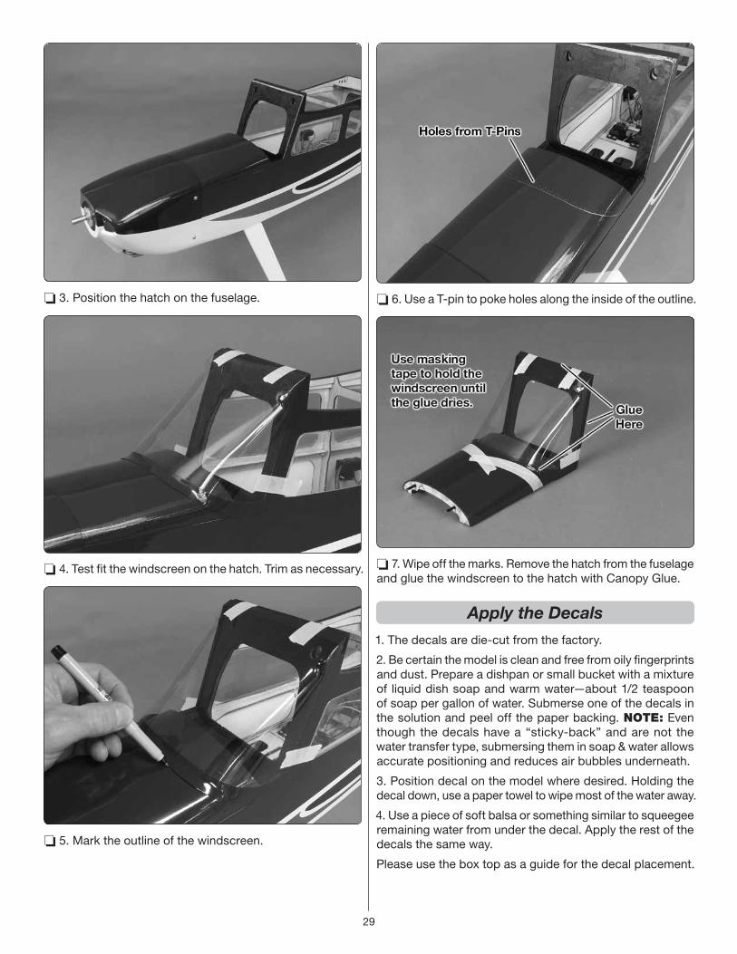
❏ 3. Position the hatch on the fuselage.
❏ 4. Test fit the windscreen on the hatch. Trim as necessary.
❏ 5. Mark the outline of the windscreen.
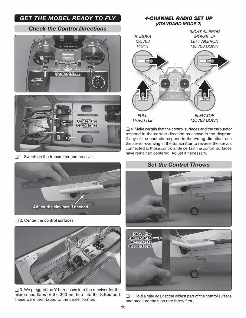
❏ 6. Use a T-pin to poke holes along the inside of the outline.
❏ 7. Wipe off the marks. Remove the hatch from the fuselage
and glue the windscreen to the hatch with Canopy Glue.
Apply the Decals
1. The decals are die-cut from the factory.
2. Be certain the model is clean and free from oily fi ngerprints
and dust. Prepare a dishpan or small bucket with a mixture
of liquid dish soap and warm water—about 1/2 teaspoon
of soap per gallon of water. Submerse one of the decals in
the solution and peel off the paper backing. NOTE: Even
though the decals have a “sticky-back” and are not the
water transfer type, submersing them in soap & water allows
accurate positioning and reduces air bubbles underneath.
3. Position decal on the model where desired. Holding the
decal down, use a paper towel to wipe most of the water away.
4. Use a piece of soft balsa or something similar to squeegee
remaining water from under the decal. Apply the rest of the
decals the same way.
Please use the box top as a guide for the decal placement.
30
GET THE MODEL READY TO FLY
Check the Control Directions
❏ 1. Switch on the transmitter and receiver.
❏ 2. Center the control surfaces.
❏ 3. We plugged the Y-harnesses into the receiver for the
aileron and flaps or the 300 mm hub into the S.Bus port.
These were then taped to the center former.
FULLTHROTTLE
RUDDERMOVESRIGHT
ELEVATORMOVES DOWN
RIGHT AILERONMOVES UP
LEFT AILERONMOVES DOWN
4-CHANNEL RADIO SET UP(STANDARD MODE 2)
❏ 4. Make certain that the control surfaces and the carburetor
respond in the correct direction as shown in the diagram.
If any of the controls respond in the wrong direction, use
the servo reversing in the transmitter to reverse the servos
connected to those controls. Be certain the control surfaces
have remained centered. Adjust if necessary.
Set the Control Throws
❏ 1. Hold a ruler against the widest part of the control surface
and measure the high rate throw fi rst.

31
Pushrod Farther Out
Pushrod Farther Out
LESSTHROW
Pushrod Closer InMORETHROW
MORETHROW
Pushrod Closer In
LESSTHROW
❏ 2. Adjust the location of the pushrod on the servo arm or
on the control horn fi rst. Then, use the endpoint adjustment
in your transmitter to fi ne tune the throws.
❏ 3. Measure and set the low rate throws. Measure and
set the high and low rate throws for the rest of the control
surfaces the same way.
If your radio does not have dual rates, we recommend setting
the throws at the high rate settings.
These are the recommended control surface throws:
EL
EV
AT
OR
HIGH RATE LOW RATE
3/4"[19 mm]
21°
Up
3/4"[19 mm]
21°
Down
1/2"[13 mm]
14°
Up
1/2"[13 mm]
14°
Down
3/4"[19mm]
17°
Up
3/4"[19mm]
17°
Down
1/2"[13 mm]
12°
Up
1/2"[13 mm]
12°
Down
1-1/4" [32mm] 29°Down
1-3/8"[35 mm]
15°
Right
1-3/8"[35 mm]
15°
Left
1"[25 mm]
11°
Right
1"[25 mm]
11°
Left
RU
DD
ER
AIL
ER
ON
S
FLAPS
❏ 4. Once the throws are set, apply a drop of threadlocker
to the threads and tighten the 4-40 nuts against the clevises.
Slide the silicone retainers over the clevises.
IMPORTANT: Now that you have the throws
set, be sure to set the failsafe on the radio.
The failsafe must stop the motor if the signal
is lost.
Install the Propeller
❏ 1. Balance the propeller.

32
❏ 2. Install the propeller. Drill holes through the propeller if
necessary.
ELECTRIC ONLY: Install the spinner adapter (GPMQ4584)
before installing the spinner cone.
❏ 3. Install the spinner cone.
❏ 4. Install the plastic floor.
Balance the Model Laterally
ELECTRIC ONLY: Install the fl ight batteries, but do not
plug the batteries into the ESC.
❏ 1. With the wing level, have an assistant help you lift the
model by the engine propeller shaft and the bottom of the
fuse under the TE of the fi n. Do this several times.
❏ 2. If one wing always drops when you lift the model, it
means that side is heavy. Balance the airplane by adding
weight to the other wing tip. An airplane that has been
laterally balanced will track better in loops and other
maneuvers.
Balance the Model (C.G.)
DO NOT OVERLOOK THIS IMPORTANT PROCEDURE.
A model that is not properly balanced may be unstable and
possibly unfl yable.
5-7/16" [114 mm]4 -1/2" [138 mm]
❏ 1. Mark the C.G range.
❏ 2. With the plane ready to fl y, with an empty fuel tank or
motor batteries installed, use a Great Planes C.G. Machine or
apply narrow (1/16" [2mm]) strips of tape at the front and rear

33
C.G. locations so you will be able to feel them when lifting the
model with your fi ngers to check the C.G. location. Do not
at any time balance the model outside this C.G. range.
❏ 3. Use Great Planes “stick on” weight (GPMQ4485) to
balance the plane. Place incrementally increasing amounts
of weight on the bottom of the fuselage over the location
where it would be mounted inside until the model balances. A
good place to add stick-on nose weight is to the fi rewall. Do
not attach weight to the cowl—this will cause stress on the
cowl and could cause the cowl to crack at the screw holes.
Once you have determined if additional weight needs to be
installed, permanently attach the weight with glue or screws.
If tail weight is needed, remove the covering from over the
weight hatch, install the weight and install the hatch cover.
❏ 4. IMPORTANT: If you found it necessary to add any
weight, recheck the C.G. after the weight has been installed.
PREFLIGHT
Identify Your Model
You should always have your name, address, telephone
number and AMA number on or inside your model. It is
required at all AMA R/C club fl ying sites and AMA sanctioned
fl ying events. Fill out the identifi cation tag on the decal sheet
and place it on or inside your model.
Charge the Batteries
Always charge your transmitter and receiver batteries the night
before you go fl ying, and at other times as recommended
by the radio manufacturer.
CAUTION: Unless the instructions that came with your
radio system state differently, the initial charge on new
transmitter and NiMH receiver batteries should be done
for 15 hours using the slow-charger that came with the
radio system. This will “condition” the batteries so that the
next charge may be done using the fast-charger of your
choice. If the initial charge is done with a fast-charger the
batteries may not reach their full capacity and you may be
fl ying with batteries that are only partially charged.
Ground Check and Range Check
Make sure the engine idles reliably, transitions smoothly
and maintains full power indefi nitely. Shut the engine off
and inspect the model closely, making sure all fasteners,
pushrods and connections have remained tight and the hinges
are secure. Follow the radio manufacturer's instructions to
ground check the operational range of your radio before
the fi rst fl ight of the day. This should be done once with
the engine off and once with the engine running at various
speeds. If the control surfaces do not respond correctly, do
not fl y! Find and correct the problem fi rst. Look for loose
servo connections or broken wires, corroded wires on old
servo connectors, poor solder joints in your battery pack or
a defective battery cell.
ENGINE SAFETY PRECAUTIONS
Failure to follow these safety precautions may result in severe injury to yourself and others.
● Keep all engine fuel in a safe place, away from high heat,
sparks or fl ames, as fuel is very fl ammable. Do not smoke
near the engine or fuel; and remember that engine exhaust
gives off a great deal of deadly carbon monoxide. Therefore
do not run the engine in a closed room or garage.
● Get help from an experienced pilot when learning to
operate engines.
● Use safety glasses when starting or running engines.
● Use a “chicken stick” or electric starter to start the engine.
If you do flip the propeller with your fingers, wear a heavy
leather glove, such as a welder’s glove. When hand starting
gas engines, if the engine should backfire, the large prop
can cause severe injury to your hand and fingers.
● Do not run the engine in an area of loose gravel or sand;
the propeller may throw such material in your face or eyes.
● Keep your face and body as well as all spectators away
from the plane of rotation of the propeller as you start and
run the engine.

34
● Keep these items away from the prop: loose clothing, shirt
sleeves, ties, scarfs, long hair or loose objects such as
pencils or screwdrivers that may fall out of shirt or jacket
pockets into the prop.
● Stop the engine before making any engine adjustments.
● The engine and muffl er get hot! Do not touch them during
or right after operation. Make sure fuel lines are in good
condition so fuel will not leak onto a hot engine, causing
a fi re.
● To stop a gasoline powered engine an on/off switch must
be connected to the engine ignition. Do not throw anything
into the propeller of a running engine.
ELECTRIC MOTOR SAFETY PRECAUTIONS
● Read and follow the battery and ESC instructions carefully
for correct use and operation.
● The motor gets HOT! Do not touch it during or right after
operation.
● When working on your plane, remove the propeller if the
motor batteries will be connected.
● Always remove the motor batteries when charging.
● Follow the charging instructions included with your charger
for charging LiPo batteries. LiPo batteries can cause
serious damage if misused.
● Once the motor batteries are connected, the electric motor
can start at any time. Make sure the fail safe is set on your
radio to prevent the motor from starting if the signal is lost.
● ALWAYS unplug the motor batteries fi rst.
● NEVER switch off the transmitter with the motor batteries
plugged in.
● WARNING: Read the entire instruction sheet included
with your motor batteries. Failure to follow the instructions
could cause permanent damage to the battery and its
surroundings and cause bodily harm!
● ONLY use a LiPo approved charger.
● NEVER use a NiCd/NiMH peak charger to charge a LiPo
battery.
● NEVER charge in excess of 4.20V per cell.
● ONLY charge through the “charge” lead.
● NEVER charge through the “discharge” lead.
● NEVER charge at currents greater than 1C unless the
battery is rated for a higher charge rate.
● ALWAYS set the charger’s output volts to match the
battery volts.
● ALWAYS charge a LiPo battery in a fi reproof location.
● NEVER trickle charge a LiPo battery.
● NEVER allow the battery temperature to exceed 150° F
(65° C).
● NEVER disassemble or modify the pack wiring in any way
or puncture the cells.
● NEVER discharge below 2.7V per cell.
● NEVER place the battery or charger on combustible
materials or leave it unattended during charge or discharge.
● ALWAYS KEEP OUT OF THE REACH OF CHILDREN.
● NEVER charge the battery in the plane.
● ALWAYS remove the battery from the plane after a crash.
Set it aside in a safe location for at least 20 minutes. If the
battery is damaged in the crash it could catch fi re.
● If the battery starts to swell, quickly move the battery to
a safe location, preferably outside. Place it in a bucket,
covering the battery with sand. Never use water to try
and put out a LiPo fi re.
AMA SAFETY CODE (excerpts)
Read and abide by the following excerpts from the Academy
of Model Aeronautics Safety Code. For the complete Safety
Code refer to Model Aviation magazine, the AMA web site
or the Code that came with your AMA license.
General
1) I will not fl y my model aircraft in sanctioned events, air
shows, or model fl ying demonstrations until it has been
proven to be airworthy by having been previously, successfully
fl ight tested.
2) I will not fl y my model aircraft higher than approximately
400 feet within 3 miles of an airport without notifying the
airport operator. I will give right-of-way and avoid fl ying in the
proximity of full-scale aircraft. Where necessary, an observer
shall be utilized to supervise fl ying to avoid having models
fl y in the proximity of full-scale aircraft.
3) Where established, I will abide by the safety rules for the
fl ying site I use, and I will not willfully and deliberately fl y my
models in a careless, reckless and/or dangerous manner.
5) I will not fl y my model unless it is identifi ed with my name
and address or AMA number, on or in the model. Note: This
does not apply to models while being fl own indoors.
7) I will not operate models with pyrotechnics (any device
that explodes, burns, or propels a projectile of any kind).
Radio Control
1) I will have completed a successful radio equipment ground
check before the fi rst fl ight of a new or repaired model.
2) I will not fl y my model aircraft in the presence of spectators
until I become a qualified flier, unless assisted by an
experienced helper.
3) At all fl ying sites a straight or curved line(s) must be
established in front of which all fl ying takes place with the
other side for spectators. Only personnel involved with fl ying
the aircraft are allowed at or in the front of the fl ight line.
Intentional fl ying behind the fl ight line is prohibited.
4) I will operate my model using only radio control frequencies
currently allowed by the Federal Communications Commission.

35
5) I will not knowingly operate my model within three miles of any pre-existing fl ying site except in accordance with the frequency sharing agreement listed [in the complete AMA Safety Code].
9) Under no circumstances may a pilot or other person touch a powered model in fl ight; nor should any part of the model other than the landing gear, intentionally touch the ground, except while landing.
FLYING
The Avistar 30cc ARF is a great-fl ying model that fl ies smoothly and predictably. However, it does not possess the self-recovery characteristics of a primary R/C trainer and should be fl own only by beginners with an experienced R/C pilot or instructor.
Fuel Mixture Adjustments
A fully cowled engine may run at a higher temperature than an un-cowled engine. For this reason, the fuel mixture should be richened so the engine runs at about 200 rpm below peak speed. By running the engine slightly rich, you will help prevent dead-stick landings caused by overheating.
CAUTION (THIS APPLIES TO ALL R/C AIRPLANES): If, while fl ying, you notice an alarming or unusual sound such as a low-pitched “buzz,” this may indicate control surface fl utter. Flutter occurs when a control surface (such as an aileron or elevator) or a fl ying surface (such as a wing or stab) rapidly vibrates up and down (thus causing the noise). In extreme cases, if not detected immediately, fl utter can actually cause the control surface to detach or the fl ying surface to fail, thus causing loss of control followed by an impending crash. If fl utter is detected, slow the model immediately and land as soon as safely possible. Identify which surface fl uttered (so the problem may be resolved) by checking all the servo grommets for deterioration or signs of vibration. Make certain all pushrod linkages are secure and free of play. If it fl uttered once, under similar circumstances it will probably fl utter again unless the problem is fi xed. Some things which can cause fl utter are; Excessive hinge gap; Not mounting control horns solidly; Poor fi t of clevis pin in horn; Side-play of wire pushrods caused by large bends; Excessive free play in servo gears; Insecure servo mounting; and one of the most prevalent causes of fl utter; Flying an over-powered model at excessive speeds.
Takeoff
Before taking off, see how the model handles on the ground by doing a few practice runs at low speeds on the runway. Hold “up” elevator to keep the tail wheel on the ground. If necessary, adjust the tail wheel so the model will roll straight down the runway.
Remember to takeoff directly into the wind. When you’re ready, point the model straight down the runway, hold a bit of up elevator to keep the tail on the ground to maintain tail wheel steering (on a tail dragger model), then gradually advance the throttle. As the model gains speed, decrease up elevator allowing the tail to come off the ground. One of the most important things to remember with a tail dragger
is to always be ready to apply right rudder to counteract engine torque. Gain as much speed as your runway and fl ying site will practically allow before gently applying up elevator, lifting the model into the air. At this moment it is likely that you will need to apply more right rudder to counteract engine torque. Be smooth on the elevator stick, allowing the model to establish a gentle climb to a safe altitude before turning into the traffi c pattern.
Flight
It is a good idea to have an assistant on the fl ight line with you to keep an eye on other traffi c. Take it easy with the Avistar 30cc ARF for the fi rst few fl ights, gradually getting acquainted with it as you gain confi dence. We have found that the high rate rudder throw is only needed for ground handling. Low rate rudder is best for fl ying. Adjust the trims to maintain straight and level fl ight. After fl ying around for a while, and while still at a safe altitude with plenty of fuel, practice slow fl ight and execute practice landing approaches by reducing the throttle and lowering the fl aps to see how the model handles at slower speeds. Add power to see how she climbs as well. Continue to fl y around, executing various maneuvers and making mental notes of what trim or C.G. changes may be required to fi ne tune the model so it fl ies the way you like. Mind your fuel level, but use this fi rst fl ight to become familiar with your model before landing.
With the electric setup, if using the recommended 5000mAh LiPo batteries, set your transmitter timer for 6-minutes for the first flight. After you land, check the capacity of the batteries and adjust the timer as needed. With good throttle management, 10 minute flights or more are possible,
Landing
The Avistar 30cc lands similar to a .60 size sport plane. It does
not require fl aps to land, but the fl aps will allow the plane
to land slower and are great practice for the pilot that has
never used fl aps. Flaps increase lift and drag, thus reducing
rollout after touchdown (not as much of a factor on grass
runways). To initiate a landing approach, lower the throttle
while on the downwind leg. If using fl aps, allow the model to
slow before extending them. Continue to lose altitude, but
maintain airspeed by keeping the nose down as you turn onto
the crosswind leg. Make your fi nal turn toward the runway
(into the wind) keeping the nose down to maintain airspeed
and control. If using fl aps, keep a few additional “clicks” of
power so the model doesn’t slow too much. Level the attitude
when the model reaches the runway threshold, modulating
the throttle as necessary to maintain your glide path and
airspeed. If you are going to overshoot, smoothly advance
the throttle (always ready on the right rudder to counteract
torque) and retract the fl aps when enough airspeed is gained.
Climb out to make another attempt. When the model is a
foot or so off the deck, smoothly increase up elevator until
it gently touches down. Once the model is on the runway
and has lost fl ying speed, hold up elevator to place the tail
on the ground, regaining tail wheel control.
NOTE: If ever the occasion arises when a dead-stick landing
must be performed, do not extend the fl aps until certain the

36
model will be able to reach the landing zone (on dead-stick
landings it is common to land with no fl aps at all). Without
engine power, fl aps can unexpectedly reduce the model’s
range, thus causing you to come up short of the fi eld.
Have a goal or fl ight plan in mind each time you fl y. This may
be learning or improving a maneuver or learning how the
model behaves at certain speeds and control rates. Every
maneuver should be deliberate, not impulsive. A fl ight plan
reduces the chances of crashing your model because of
poor planning and impulsive moves.
Have a ball! But always stay in control and fl y in a safe manner.
GOOD LUCK AND GREAT FLYING!
QTY. DESCRIPTION QTY. DESCRIPTION
PARTS LIST
1 Fuel Tank stopper
1 Fuel tank stopper screw
1 Fuel tank stopper plate large
1 Fuel tank stopper plate small
2 clunks
1 Long brass tube
2 Short brass tube
8 small nylon tie straps
1 Spinner backplate
1 Spinner bolt
1 Spinner backplate adapter
1 Plastic fl oor
3 16.5" outer pushrod tube
2 Hook and loop material 300mm
1 Tail gear bracket
1 Tail gear spacer
1 Tail gear spacer set screw
1 Tail gear bushing
1 Tail gear wire support
1 Tail gear wheel collar
1 Tail gear wheel collar set screw
7 Extra large control horns
3 Control horn back plates
3 Plywood engine mount spacers
2 10 x 30mm Wing dowels
1 8 x 30mm wing alignment dowel
4 Plywood motor mount top and bottom
4 Plywood motor mount sides
4 Plywood motor mount ends w/tabs
2 Plywood motor mount ends no tabs
1 Plywood outer pushrod tube support long
1 Plywood outer pushrod tube support short
1 Fuselage weight cover
7 4-40 Solder clevis
4 4-40 x 6" metal pushrod
7 4-40 metal clevis
23 #4 x 1/2" sheet metal screw
7 4-40 nut
16 silicone clevis keeper
2 3/16" axle
2 3/16" axle nut
4 3/16" Wheel collar
4 6-32 x 1/4" socket head cap screw
4 4-40 x 1/2" machine screw
11 #4 fl at washer
4 #4 lock washer
8 6-32 x 3/4" socket head cap screw
8 #6 fl at washer
8 #6 lock washer
8 8-32 Blind nuts
4 8-32 x 3/4" socket head cap screw
4 8-32 x 1" socket head cap screw
8 #8 fl at washer
8 #8 Lock washer
12 4-40 x 1" socket head cap screw
3 4-40 x 48" threaded rod
1 2-56 x 36" theaded pushrod
2 1/4-20 x 2" nylon wing bolt
1 aluminum fuel plug
11 #2 x 3/8" sheet metal screw
11 #2 fl at washers
1 Brass screw lock connector
1 screw lock retainer
1 4-40 x 1/4" socket head cap screw
1 white inner pushrod tube
4 2-56 x 1" threaded stud
2 2-56 pivot balls
2 2-56 nut
2 Nylon pivot ball sockets
2 nylon clevis


![INSTRUCTION MANUAL - Hobbicomanuals.hobbico.com/gpm/gpma1330-manual-v1_2.pdf · INSTRUCTION MANUAL Length: 60" [1,524mm] Weight: 10.25 lbs ... SAFETY PRECAUTIONS ... Dead Center ™](https://img.pdfslide.net/doc/110x75/5aafd1a47f8b9a59478dd005/instruction-manual-manual-length-60-1524mm-weight-1025-lbs-safety-precautions.jpg)