Embed Size (px)
Citation preview

INSTRUCTION MANUAL
7 1/4" CirCular Saw with laSer line 054-8347-0
MD
7 1/4" CIRCULAR SAw wITh LASeR LINe - 054-8347-0
2
7 1/4" CIRCULAR SAw wITh LASeR LINe - 054-8347-0
taBl
e OF
COn
tent
S
teChniCal SPeCiFiCatiOnS 3
SaFetY GuiDelineS 4–11
DeSCriPtiOn 12
OPeratinG inStruCtiOnS 13–23
MaintenanCe 24–26
trOuBleShOOtinG 27
PartS liSt 28–30
warrantY 31–32
if any parts are missing or damaged, or if you have any questions, please call our toll-free helpline at 1-800-689-9928.
Read and understand this instruction manual thoroughly before using the product. It contains important information for your safety as well as operating and maintenance advice.
Keep this instruction manual for future use. Should this product be passed on to a third party, then this instruction manual must be included.
7 1/4" CIRCULAR SAw wITh LASeR LINe - 054-8347-07 1/4" CIRCULAR SAw wITh LASeR LINe - 054-8347-0
3 4rules for safe operation
WARNING!Safety symbols in this Instruction Manual are used to flag possible dangers. The safety symbols and their explanations require your full understanding. The safety warnings do not, by themselves, eliminate any danger, nor are they substitutes for proper accident prevention measures.
WARNING!This Safety Alert Symbol indicates caution, warning, or danger. Failure to obey a safety warning can result in serious injury to yourself or others. To reduce the risk of injury, fire, or electric shock, always follow the safety precautions.
Know your toolTo operate this tool, carefully read this Instruction Manual and all labels affixed to the 7 1/4" Circular Saw with Laser Line before using. Keep this Instruction Manual available for future reference.
importantThis tool should only be serviced by a qualified service technician. For more information, call the toll-free helpline at 1-800-689-9928.
read all instructions thoroughly
Save these instructions
Safety guidelines for power tools
WARNING!Read all safety warnings and instructions. Failure to follow the warnings and instructions may result in electric shock, fire and/or serious injury. Save all warnings and instructions for future reference. The term “power tool” in the warnings refers to your mains-operated (corded) power tool or battery-operated (cordless) power tool.
SaFe
tY G
uiDe
line
S
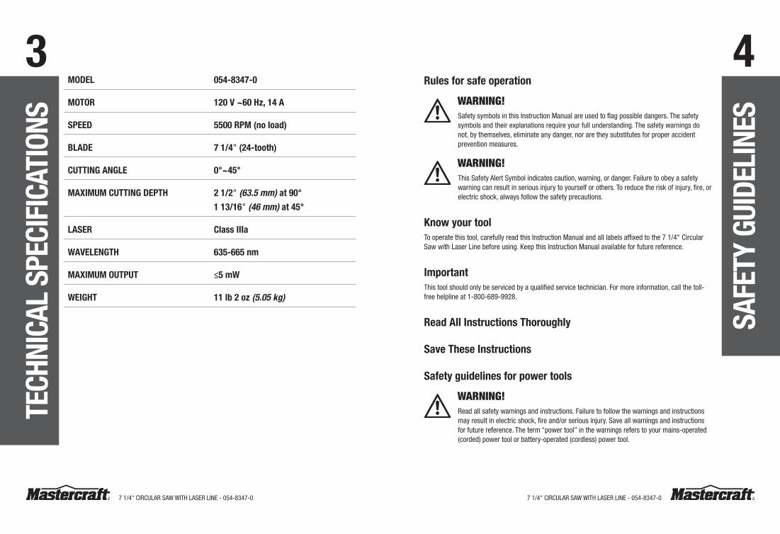
MODel 054-8347-0
MOtOr 120 V ~60 hz, 14 a
SPeeD 5500 rPM (no load)
BlaDe 7 1/4" (24-tooth)
CuttinG anGle 0°~45°
MaXiMuM CuttinG DePth 2 1/2" (63.5 mm) at 90°
1 13/16" (46 mm) at 45°
laSer Class iiia
waVelenGth 635-665 nm
MaXiMuM OutPut ≤5 mw
weiGht 11 lb 2 oz (5.05 kg)
teCh
niCa
l SP
eCiF
iCat
iOnS
7 1/4" CIRCULAR SAw wITh LASeR LINe - 054-8347-07 1/4" CIRCULAR SAw wITh LASeR LINe - 054-8347-0
5 6•Removeanyadjustingkeysorwrenchesbeforeturningthepowertoolon.A wrench or a
key left attached to a rotating part of the power tool may result in personal injury.
•Donotoverreach.Keepproperfootingandbalanceatalltimes.This enables better control of the power tool in unexpected situations.
• Dressproperly.Donotwearlooseclothingorjewellery.Keepyourhair,clothingandglovesawayfrommovingparts.Loose clothes, jewellery or long hair can get caught in moving parts.
• Ifdevicesareprovidedfortheconnectionofdustextractionandcollectionfacilities,verifytheseareconnectedandproperlyused.The use of these devices can reduce dust-related hazards.
use and care of power tools• Donotforcethepowertool.Usethecorrectpowertoolforyourapplication.The correct
power tool will do the job better and more safely when used at the rate at which it was designed to work.
•Donotusethepowertooliftheswitchdoesnotturnitonandoff.Any power tool that cannot be controlled with the switch is dangerous, and must be repaired.
•Disconnecttheplugfromthepowersourceand/ordisconnectthebatterypackfromthepowertoolbeforemakinganyadjustments,changingaccessories,orstoringthepowertool.Such preventive safety measures reduce the risk of starting the power tool accidentally.
• Storeidlepowertoolsoutofthereachofchildren,anddonotallowpersonswhoareunfamiliarwiththepowertoolortheseinstructionstooperatethepowertool.Power tools are dangerous in the hands of untrained users.
•Maintainpowertools.Checkformisalignmentorbindingofmovingparts,brokenparts,andanyotherconditionthatmayaffectthepowertool’soperation.Ifdamaged,havethepowertoolrepairedbeforeuse.Many accidents are caused by poorly maintained power tools.
•Keepcuttingtoolssharpandclean.Properly maintained cutting tools with sharp cutting edges are less likely to bind, and are easier to control.
•Usethepowertool,accessoriestoolbits,etc.inaccordancewiththeseinstructions,takingintoaccounttheworkingconditionsandtheworktobeperformed. Using the power tool for operations different from those for which it is intended could result in a hazardous situation.
Service•Haveyourpowertoolservicedbyaqualifiedrepairpersonusingonlyidenticalreplacementparts.This will ensure that the safety of the power tool is maintained.
SaFe
tY G
uiDe
line
S
work area safety•Keepworkareacleanandwelllit.Cluttered or dark areas invite accidents.
•Donotoperatepowertoolsinanexplosiveenvironment,suchasinthepresenceofflammableliquids,gasesordust.Power tools create sparks that may ignite the dust or fumes.
•Keepchildrenandbystandersawaywhileoperatingapowertool.Distractions can cause you to lose control.
electrical safety• Theplugonthepowertoolmustmatchtheoutlet.Nevermodifythepluginanyway.Donotuseadaptorplugswithearthed(grounded)powertools.Unmodified plugs and matching outlets will reduce the risk of electric shock.
•Avoidbodycontactwithearthedorgroundedsurfacessuchaspipes,radiators,rangesandrefrigerators.There is an increased risk of electric shock if your body is earthed or grounded.
•Donotexposepowertoolstorainorwetconditions.water entering a power tool will increase the risk of electric shock.
•Donotabusethecord.Neverusethecordforcarrying,pullingorunpluggingthepowertool.Keepthecordawayfromheat,oil,sharpedgesormovingparts.Damaged or entangled cords increase the risk of electric shock.
•Whenoperatingapowertooloutdoors,useanextensioncordthatissuitableforoutdooruse.The use of a cord that is suitable for outdoor use reduces the risk of electric shock.
• Ifoperatingapowertoolinadamplocationisunavoidable,useapowersupplythatisprotectedbyaground-faultcircuitinterrupter.The use of a GFCI reduces the risk of electric shock.
Personal safety• Stayalert,watchwhatyouaredoing,andusecommonsensewhenoperatingapowertool.Donotuseatoolwhiletiredorundertheinfluenceofdrugs,alcohol,ormedication.A moment of inattention while operating a power tool may result in serious personal injury.
•Usepersonalprotectiveequipment.Alwaysweareyeprotection.Protective equipment such as a dust mask, non-skid safety shoes, a hard hat, or hearing protection used for appropriate conditions will reduce personal injuries.
• Preventunintentionalstarting.Verifythattheswitchisintheoffpositionbeforeconnectingtothepowersourceand/orbatterypack,andbeforepickinguporcarryingthetool.Carrying power tools with your finger on the switch or connecting a power tool that has the switch on invites accidents.
SaFe
tY G
uiDe
line
S
7 1/4" CIRCULAR SAw wITh LASeR LINe - 054-8347-07 1/4" CIRCULAR SAw wITh LASeR LINe - 054-8347-0
7 8•Adjustthecuttingdepthtothethicknessoftheworkpiece.. Less than a full tooth of the
blade teeth should be visible below the work piece.
•Neverholdpiecebeingcutinyourhandsoracrossyourleg.Securetheworkpiecetoastableplatform. It is important to support the work properly to minimize body exposure, blade binding, or loss of control.
•Holdpowertoolbyinsulatedgrippingsurfaceswhenperforminganoperationwherethecuttingtoolmaycontacthiddenwiringoritsowncord.Contact with a ‘live’ wire will also make exposed metal parts of the power tool ‘live’ and shock the operator.
•Whenrippingalwaysusearipfenceorstraightedgeguide. This improves the accuracy of cut and reduces the chance of blade binding.
• Alwaysusebladeswithcorrectsizeandshape(diamondversusround)ofarborholes. Blades that do not match the mounting hardware of the saw will run eccentrically, causing loss of control.
•Neverusedamagedorincorrectbladewashersorbolt.The blade washers and bolt were specially designed for your saw, for optimum performance and safety of operation.
CauSeS anD OPeratOr PreVentiOn OF KiCKBaCK
• kickback is sudden reaction to a pinched, bound or misaligned saw blade, causing an uncontrolled saw to lift up and out of the workpiece toward the operator;
•when the blade is pinched or bound tightly by the kerf closing down, the blade stalls and the motor reaction drives the unit rapidly back toward the operator;
• if the blade becomes twisted or misaligned in the cut, the teeth at the back edge of the blade can dig into the top surface if the wood causing the blade to climb out the kerf and jump back toward the operator.
KiCKBaCK iS the reSult OF Saw MiSuSe anD/Or inCOrreCt OPeratiOn PrOCeDureS Or COnDitiOnS anD Can Be aVOiDeD BY taKinG PrOPer PreCautiOnS aS GiVen BelOw.
•Maintainafirmgripwithbothhandsonthesawandpositionyourarmstoresistkickbackforces.Positionyourbodytoeithersideoftheblade,butnotinlinewiththeblade. Kickback could cause the saw to jump backwards, but kickback forces can be controlled by the operator, if proper precautions are taken.
•Whenbladeisbinding,orwheninterruptingacutforanyreason,releasethetriggerandholdthesawmotionlessinthematerialuntilthebladecomestoacompletestop.Neverattempttoremovethesawfromtheworkorpullthesawbackwardwhilethebladeisinmotionorkickbackmayoccur. Investigate and take corrective actions to eliminate the cause of blade binding.
SaFe
tY G
uiDe
line
S
additional safety rules for laser lightsThelaserlight/laserradiationusedinthissystemisClassIII,withmaximum5mWAndwavelengthsof635-665nm.Undernormalcircumstances,theselasersdonotpresentanopticalhazard,butstaringatthebeammaycauseflashblindness.
WARNING!Do not stare directly at the laser beam.
Ahazardmayexistifyoudeliberatelystareintothebeam.Pleaseobserveallofthefollowingsafetyrules:
• The laser must be used and maintained in accordance with the manufacturer’s instructions.
•Never aim the beam at any person or any object other than the workpiece.
• Always ensure that the laser beam is aimed at a sturdy workpiece that does not have reflective surfaces. wood and rough coated surfaces are acceptable. Bright, shiny reflective sheet steel or similar materials are not suitable for laser use, because the reflective surface could direct the beam back at the operator.
•Do not replace the laser light assembly with a different type. Repairs must be carried out by the laser manufacturer, or by an authorized agent.
• ALwAYS turn the laser beam off when not in use. Leaving the tool on increases the risk of someone inadvertently staring into the laser’s beam.
CAUTION!Using controls or adjustments or performing procedures other than those specified herein may result in hazardous radiation exposure.
Specific safety rules for circular saws
DanGer
•Keephandsawayfromcuttingareaandblade.Keepyoursecondhandonauxiliaryhandle,ormotorhousing. If both hands are holding the saw, they cannot be cut by the blade.
•Donotreachunderneaththeworkpiece.The guard cannot protect you from the blade below the work piece.
SaFe
tY G
uiDe
line
S
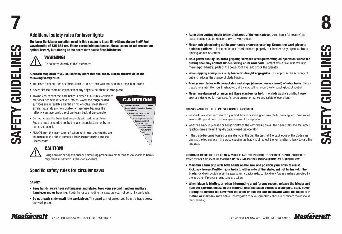
CAUTIONAVOID EXPOSURE
Laser radiation is emitted through this aperture.
LASER RADIATION. DO NOT STARE INTO BEAM
Wave length: 635-665nm. Max output: 5mW.
Class IIIA Laser Product. Complies
with FDA 21CFR Parts 1040.10
and 1040.11.
7 1/4" CIRCULAR SAw wITh LASeR LINe - 054-8347-07 1/4" CIRCULAR SAw wITh LASeR LINe - 054-8347-0
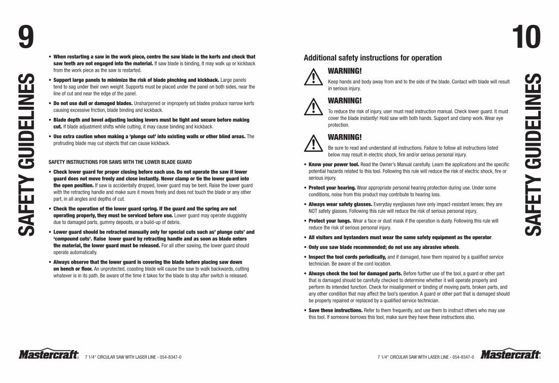
9 10additional safety instructions for operation
WARNING!Keep hands and body away from and to the side of the blade. Contact with blade will result in serious injury.
WARNING!To reduce the risk of injury, user must read instruction manual. Check lower guard. It must cover the blade instantly! hold saw with both hands. Support and clamp work. wear eye protection.
WARNING!Be sure to read and understand all instructions. Failure to follow all instructions listed below may result in electric shock, fire and/or serious personal injury.
•Knowyourpowertool. Read the Owner’s Manual carefully. Learn the applications and the specific potential hazards related to this tool. Following this rule will reduce the risk of electric shock, fire or serious injury.
• Protectyourhearing. wear appropriate personal hearing protection during use. Under some conditions, noise from this product may contribute to hearing loss.
•Alwayswearsafetyglasses. everyday eyeglasses have only impact-resistant lenses; they are NOT safety glasses. Following this rule will reduce the risk of serious personal injury.
• Protectyourlungs.wear a face or dust mask if the operation is dusty. Following this rule will reduce the risk of serious personal injury.
•Allvisitorsandbystandersmustwearthesamesafetyequipmentastheoperator.
•Onlyusesawbladerecommended;donotuseanyabrasivewheels.
• Inspectthetoolcordsperiodically, and if damaged, have them repaired by a qualified service technician. Be aware of the cord location.
•Alwayscheckthetoolfordamagedparts. Before further use of the tool, a guard or other part that is damaged should be carefully checked to determine whether it will operate properly and perform its intended function. Check for misalignment or binding of moving parts, broken parts, and any other condition that may affect the tool’s operation. A guard or other part that is damaged should be properly repaired or replaced by a qualified service technician.
• Savetheseinstructions. Refer to them frequently, and use them to instruct others who may use this tool. If someone borrows this tool, make sure they have these instructions also.
•Whenrestartingasawintheworkpiece,centrethesawbladeinthekerfsandcheckthatsawteetharenotengagedintothematerial. If saw blade is binding, It may walk up or kickback from the work piece as the saw is restarted.
• Supportlargepanelstominimizetheriskofbladepinchingandkickback. Large panels tend to sag under their own weight. Supports must be placed under the panel on both sides, near the line of cut and near the edge of the panel.
•Donotusedullordamagedblades.Unsharpened or improperly set blades produce narrow kerfs causing excessive friction, blade binding and kickback.
•Bladedepthandbeveladjustinglockingleversmustbetightandsecurebeforemakingcut.If blade adjustment shifts while cutting, it may cause binding and kickback.
•Useextracautionwhenmakinga‘plungecut’intoexistingwallsorotherblindareas.The protruding blade may cut objects that can cause kickback.
SaFetY inStruCtiOnS FOr SawS with the lOwer BlaDe GuarD
• Checklowerguardforproperclosingbeforeeachuse.Donotoperatethesawiflowerguarddoesnotmovefreelyandcloseinstantly.Neverclamportiethelowerguardintotheopenposition.If saw is accidentally dropped, lower guard may be bent. Raise the lower guard with the retracting handle and make sure it moves freely and does not touch the blade or any other part, in all angles and depths of cut.
• Checktheoperationofthelowerguardspring.Iftheguardandthespringarenotoperatingproperly,theymustbeservicedbeforeuse.Lower guard may operate sluggishly due to damaged parts, gummy deposits, or a build-up of debris.
• Lowerguardshouldberetractedmanuallyonlyforspecialcutssuchas’plungecuts’and‘compoundcuts’.Raiselowerguardbyretractinghandleandassoonasbladeentersthematerial,thelowerguardmustbereleased.For all other sawing, the lower guard should operate automatically.
•Alwaysobservethatthelowerguardiscoveringthebladebeforeplacingsawdownonbenchorfloor.An unprotected, coasting blade will cause the saw to walk backwards, cutting whatever is in its path. Be aware of the time it takes for the blade to stop after switch is released.
SaFe
tY G
uiDe
line
S
SaFe
tY G
uiDe
line
S
7 1/4" CIRCULAR SAw wITh LASeR LINe - 054-8347-07 1/4" CIRCULAR SAw wITh LASeR LINe - 054-8347-0
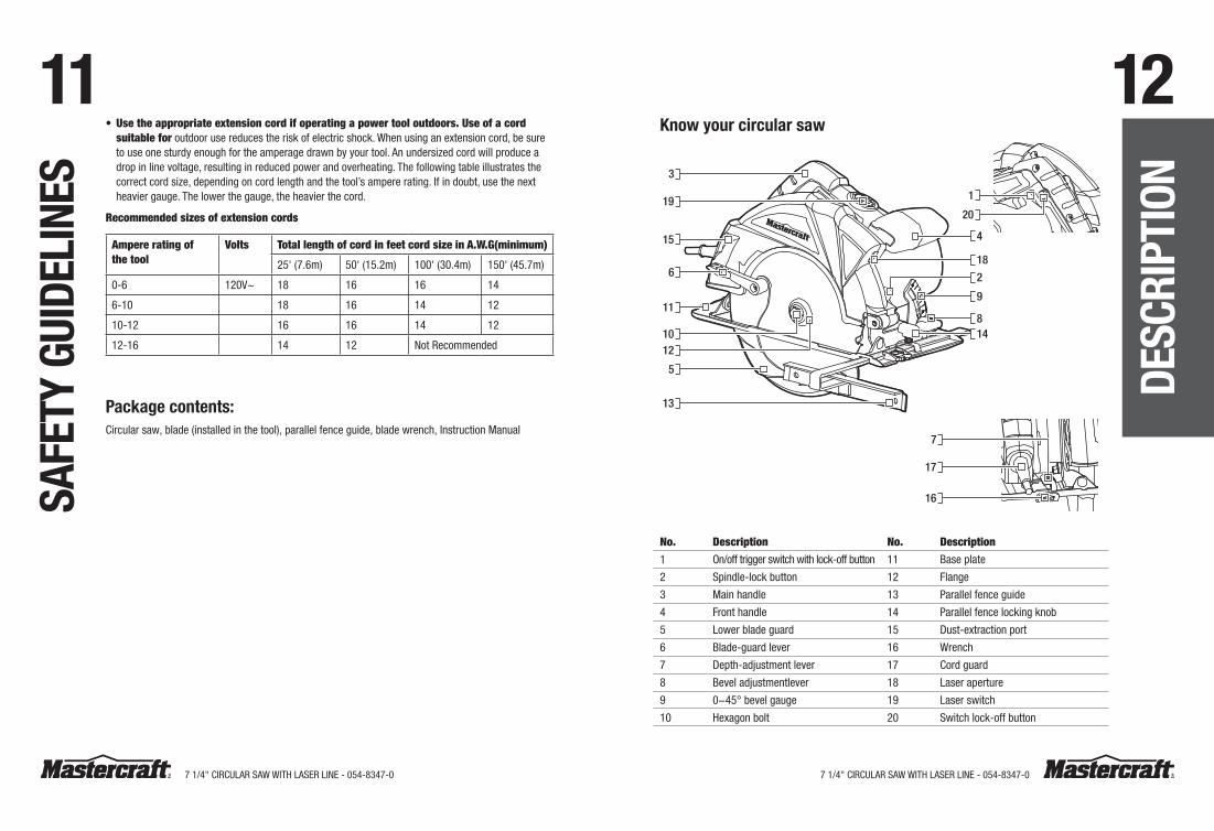
11 12Know your circular saw
3
1
15
19
11
1012
6
5
13
17
7
16
4
9
814
2
18
20
No. Description No. Description1 On/off trigger switch with lock-off button 11 Base plate
2 Spindle-lock button 12 Flange
3 Main handle 13 Parallel fence guide
4 Front handle 14 Parallel fence locking knob
5 Lower blade guard 15 Dust-extraction port
6 Blade-guard lever 16 wrench
7 Depth-adjustment lever 17 Cord guard
8 Bevel adjustmentlever 18 Laser aperture
9 0−45° bevel gauge 19 Laser switch
10 hexagon bolt 20 Switch lock-off button
•Usetheappropriateextensioncordifoperatingapowertooloutdoors.Useofacordsuitablefor outdoor use reduces the risk of electric shock. when using an extension cord, be sure to use one sturdy enough for the amperage drawn by your tool. An undersized cord will produce a drop in line voltage, resulting in reduced power and overheating. The following table illustrates the correct cord size, depending on cord length and the tool’s ampere rating. If in doubt, use the next heavier gauge. The lower the gauge, the heavier the cord.
Recommendedsizesofextensioncords
Ampereratingofthetool
Volts TotallengthofcordinfeetcordsizeinA.W.G(minimum)
25' (7.6m) 50' (15.2m) 100' (30.4m) 150' (45.7m)
0-6 120V~ 18 16 16 14
6-10 18 16 14 12
10-12 16 16 14 12
12-16 14 12 Not Recommended
Package contents:Circular saw, blade (installed in the tool), parallel fence guide, blade wrench, Instruction Manual
SaFe
tY G
uiDe
line
S
DeSC
riPt
iOn
7 1/4" CIRCULAR SAw wITh LASeR LINe - 054-8347-07 1/4" CIRCULAR SAw wITh LASeR LINe - 054-8347-0
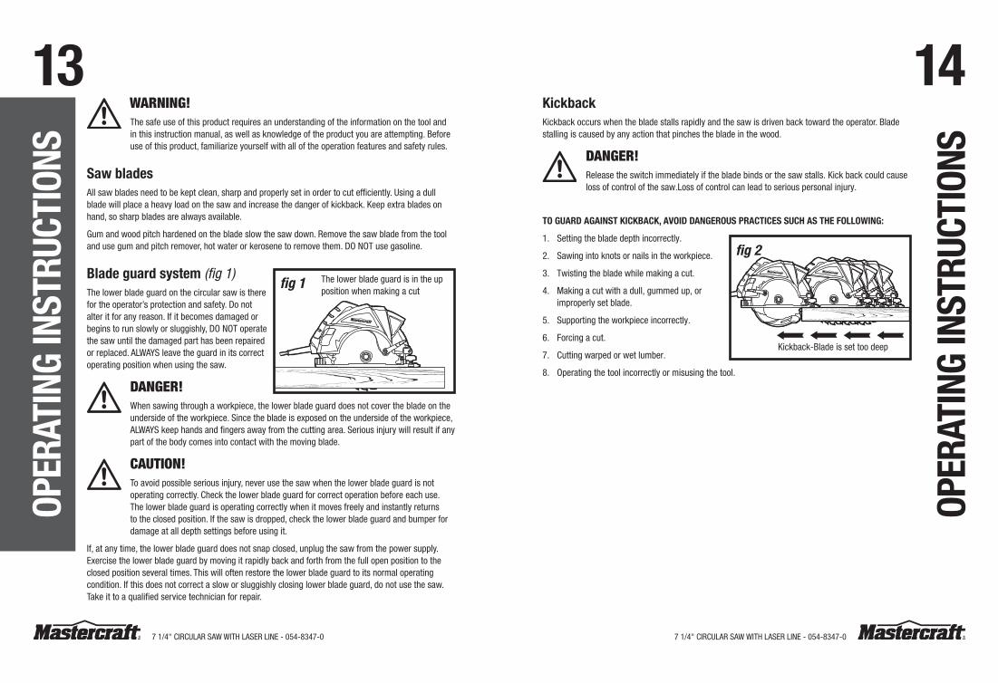
13 14KickbackKickback occurs when the blade stalls rapidly and the saw is driven back toward the operator. Blade stalling is caused by any action that pinches the blade in the wood.
DANGER!Release the switch immediately if the blade binds or the saw stalls. Kick back could cause loss of control of the saw.Loss of control can lead to serious personal injury.
tO GuarD aGainSt KiCKBaCK, aVOiD DanGerOuS PraCtiCeS SuCh aS the FOllOwinG:
1. Setting the blade depth incorrectly.
2. Sawing into knots or nails in the workpiece.
3. Twisting the blade while making a cut.
4. Making a cut with a dull, gummed up, or improperly set blade.
5. Supporting the workpiece incorrectly.
6. Forcing a cut.
7. Cutting warped or wet lumber.
8. Operating the tool incorrectly or misusing the tool.
OPer
atin
G in
Stru
CtiO
nS
WARNING!The safe use of this product requires an understanding of the information on the tool and in this instruction manual, as well as knowledge of the product you are attempting. Before use of this product, familiarize yourself with all of the operation features and safety rules.
Saw bladesAll saw blades need to be kept clean, sharp and properly set in order to cut efficiently. Using a dull blade will place a heavy load on the saw and increase the danger of kickback. Keep extra blades on hand, so sharp blades are always available.
Gum and wood pitch hardened on the blade slow the saw down. Remove the saw blade from the tool and use gum and pitch remover, hot water or kerosene to remove them. DO NOT use gasoline.
Blade guard system (fig 1)The lower blade guard on the circular saw is there for the operator’s protection and safety. Do not alter it for any reason. If it becomes damaged or begins to run slowly or sluggishly, DO NOT operate the saw until the damaged part has been repaired or replaced. ALwAYS leave the guard in its correct operating position when using the saw.
DANGER!when sawing through a workpiece, the lower blade guard does not cover the blade on the underside of the workpiece. Since the blade is exposed on the underside of the workpiece, ALwAYS keep hands and fingers away from the cutting area. Serious injury will result if any part of the body comes into contact with the moving blade.
CAUTION! To avoid possible serious injury, never use the saw when the lower blade guard is not operating correctly. Check the lower blade guard for correct operation before each use. The lower blade guard is operating correctly when it moves freely and instantly returns to the closed position. If the saw is dropped, check the lower blade guard and bumper for damage at all depth settings before using it.
If, at any time, the lower blade guard does not snap closed, unplug the saw from the power supply. exercise the lower blade guard by moving it rapidly back and forth from the full open position to the closed position several times. This will often restore the lower blade guard to its normal operating condition. If this does not correct a slow or sluggishly closing lower blade guard, do not use the saw. Take it to a qualified service technician for repair.
OPer
atin
G in
Stru
CtiO
nS
fig 1 The lower blade guard is in the up position when making a cut
fig 2
Kickback-Blade is set too deep
7 1/4" CIRCULAR SAw wITh LASeR LINe - 054-8347-07 1/4" CIRCULAR SAw wITh LASeR LINe - 054-8347-0
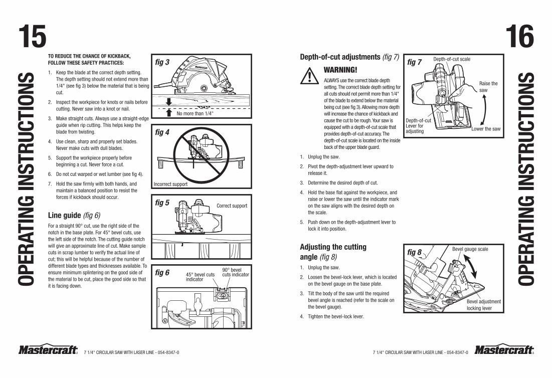
15 16tO reDuCe the ChanCe OF KiCKBaCK, FOllOw theSe SaFetY PraCtiCeS:
1. Keep the blade at the correct depth setting. The depth setting should not extend more than 1/4" (see fig 3) below the material that is being cut.
2. Inspect the workpiece for knots or nails before cutting. Never saw into a knot or nail.
3. Make straight cuts. Always use a straight-edge guide when rip cutting. This helps keep the blade from twisting.
4. Use clean, sharp and properly set blades. Never make cuts with dull blades.
5. Support the workpiece properly before beginning a cut. Never force a cut.
6. Do not cut warped or wet lumber (see fig 4).
7. hold the saw firmly with both hands, and maintain a balanced position to resist the forces if kickback should occur.
line guide (fig 6)For a straight 90° cut, use the right side of the notch in the base plate. For 45° bevel cuts, use the left side of the notch. The cutting guide notch will give an approximate line of cut. Make sample cuts in scrap lumber to verify the actual line of cut; this will be helpful because of the number of different blade types and thicknesses available. To ensure minimum splintering on the good side of the material to be cut, place the good side so that it is facing down.OP
erat
inG
inSt
ruCt
iOnS
Depth-of-cut adjustments (fig 7)
WARNING! ALwAYS use the correct blade depth setting. The correct blade depth setting for all cuts should not permit more than 1/4" of the blade to extend below the material being cut (see fig 3). Allowing more depth will increase the chance of kickback and cause the cut to be rough. Your saw is equipped with a depth-of-cut scale that provides depth-of-cut accuracy. The depth-of-cut scale is located on the inside back of the upper blade guard.
1. Unplug the saw.
2. Pivot the depth-adjustment lever upward to release it.
3. Determine the desired depth of cut.
4. hold the base flat against the workpiece, and raise or lower the saw until the indicator mark on the saw aligns with the desired depth on the scale.
5. Push down on the depth-adjustment lever to lock it into position.
adjusting the cutting angle (fig 8)1. Unplug the saw.
2. Loosen the bevel-lock lever, which is located on the bevel gauge on the base plate.
3. Tilt the body of the saw until the required bevel angle is reached (refer to the scale on the bevel gauge).
4. Tighten the bevel-lock lever.
OPer
atin
G in
Stru
CtiO
nS
fig 3
No more than 1/4"
fig 4
Incorrect support
fig 5 Correct support
fig 6 90° bevel cuts indicator45° bevel cuts
indicator
fig 7 Depth-of-cut scale
Raise the saw
Lower the saw
Depth-of-cut Lever for adjusting
Bevel gauge scale
Bevel adjustment locking lever
fig 8
7 1/4" CIRCULAR SAw wITh LASeR LINe - 054-8347-07 1/4" CIRCULAR SAw wITh LASeR LINe - 054-8347-0
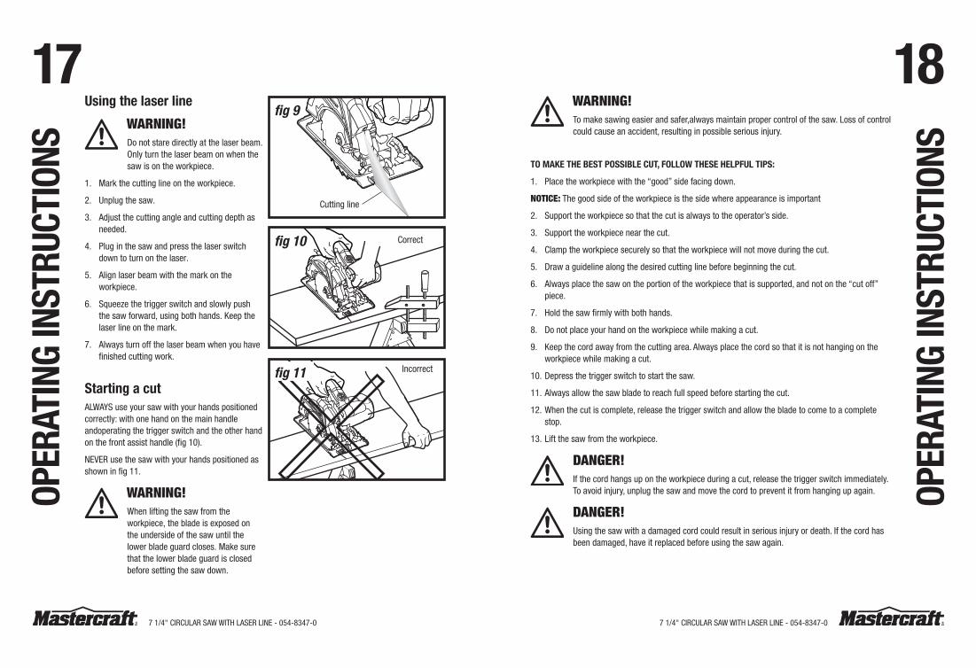
17 18using the laser line
WARNING!Do not stare directly at the laser beam. Only turn the laser beam on when the saw is on the workpiece.
1. Mark the cutting line on the workpiece.
2. Unplug the saw.
3. Adjust the cutting angle and cutting depth as needed.
4. Plug in the saw and press the laser switch down to turn on the laser.
5. Align laser beam with the mark on the workpiece.
6. Squeeze the trigger switch and slowly push the saw forward, using both hands. Keep the laser line on the mark.
7. Always turn off the laser beam when you have finished cutting work.
Starting a cutALwAYS use your saw with your hands positioned correctly: with one hand on the main handle andoperating the trigger switch and the other hand on the front assist handle (fig 10).
NeVeR use the saw with your hands positioned as shown in fig 11.
WARNING! when lifting the saw from the workpiece, the blade is exposed on the underside of the saw until the lower blade guard closes. Make sure that the lower blade guard is closed before setting the saw down.
OPer
atin
G in
Stru
CtiO
nSWARNING!To make sawing easier and safer,always maintain proper control of the saw. Loss of control could cause an accident, resulting in possible serious injury.
tO MaKe the BeSt POSSiBle Cut, FOllOw theSe helPFul tiPS:
1. Place the workpiece with the “good” side facing down.
NOTICE:The good side of the workpiece is the side where appearance is important
2. Support the workpiece so that the cut is always to the operator’s side.
3. Support the workpiece near the cut.
4. Clamp the workpiece securely so that the workpiece will not move during the cut.
5. Draw a guideline along the desired cutting line before beginning the cut.
6. Always place the saw on the portion of the workpiece that is supported, and not on the “cut off” piece.
7. hold the saw firmly with both hands.
8. Do not place your hand on the workpiece while making a cut.
9. Keep the cord away from the cutting area. Always place the cord so that it is not hanging on the workpiece while making a cut.
10. Depress the trigger switch to start the saw.
11. Always allow the saw blade to reach full speed before starting the cut.
12. when the cut is complete, release the trigger switch and allow the blade to come to a complete stop.
13. Lift the saw from the workpiece.
DANGER!If the cord hangs up on the workpiece during a cut, release the trigger switch immediately. To avoid injury, unplug the saw and move the cord to prevent it from hanging up again.
DANGER!Using the saw with a damaged cord could result in serious injury or death. If the cord has been damaged, have it replaced before using the saw again.
OPer
atin
G in
Stru
CtiO
nS
fig 10 Correct
fig 9
Cutting line
Incorrectfig 11
7 1/4" CIRCULAR SAw wITh LASeR LINe - 054-8347-07 1/4" CIRCULAR SAw wITh LASeR LINe - 054-8347-0
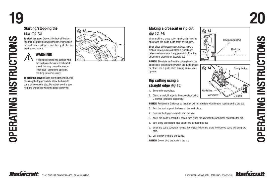
19 20Starting/stopping the saw (fig 12)Tostartthesaw:Depress the lock-off button, and then depress the switch trigger. Always allow the blade reach full speed, and then guide the saw into the work-piece.
WARNING! If the blade comes into contact with the workpiece before it reaches full speed, this may cause the saw to “kick back” toward the operator, resulting in serious injury.
Tostopthesaw:Release the trigger switch.After releasing the trigger switch, allow the blade to come to a complete stop. Do not remove the saw from the workpiece while the blade is moving.
Making a crosscut or rip cut (fig 13, 14)when making a cross cut or rip cut, align the line of cut with the blade guide notch on the base.
Since blade thicknesses vary, always make a trial cut in scrap material along a guideline to determine how much, if any, you must offset the guideline to produce an accurate cut.
NOTICE:The distance from the cutting line to the guideline is the amount by which the guide should be offset. Use a guide when making long or wide rip cuts.
rip cutting using a straight edge (fig 14)1. Secure the workpiece.
2. Clamp a straight edge to the work-piece using C-clamps (available separately).
NOTICE: Position the C-clamps so that they will not interfere with the saw housing during the cut.
3. Rest the front edge of the base on the work piece.
4. Depress the trigger switch to start the saw.
5. Allow the blade to reach full speed, then guide the saw into the workpiece and make the cut.
6. Saw along the straight edge to achieve a straight rip cut.
7. when the cut is complete, release the trigger switch and allow the blade to come to a complete stop.
8. Lift the saw from the workpiece.
NOTICE: Do not bind the blade in the cut.
fig 12
OPer
atin
G in
Stru
CtiO
nS
OPer
atin
G in
Stru
CtiO
nS
fig 13
Guide line
Blade guide notch
fig 14 Straight edge
C-clamp
Guide line
workpiece
7 1/4" CIRCULAR SAw wITh LASeR LINe - 054-8347-07 1/4" CIRCULAR SAw wITh LASeR LINe - 054-8347-0
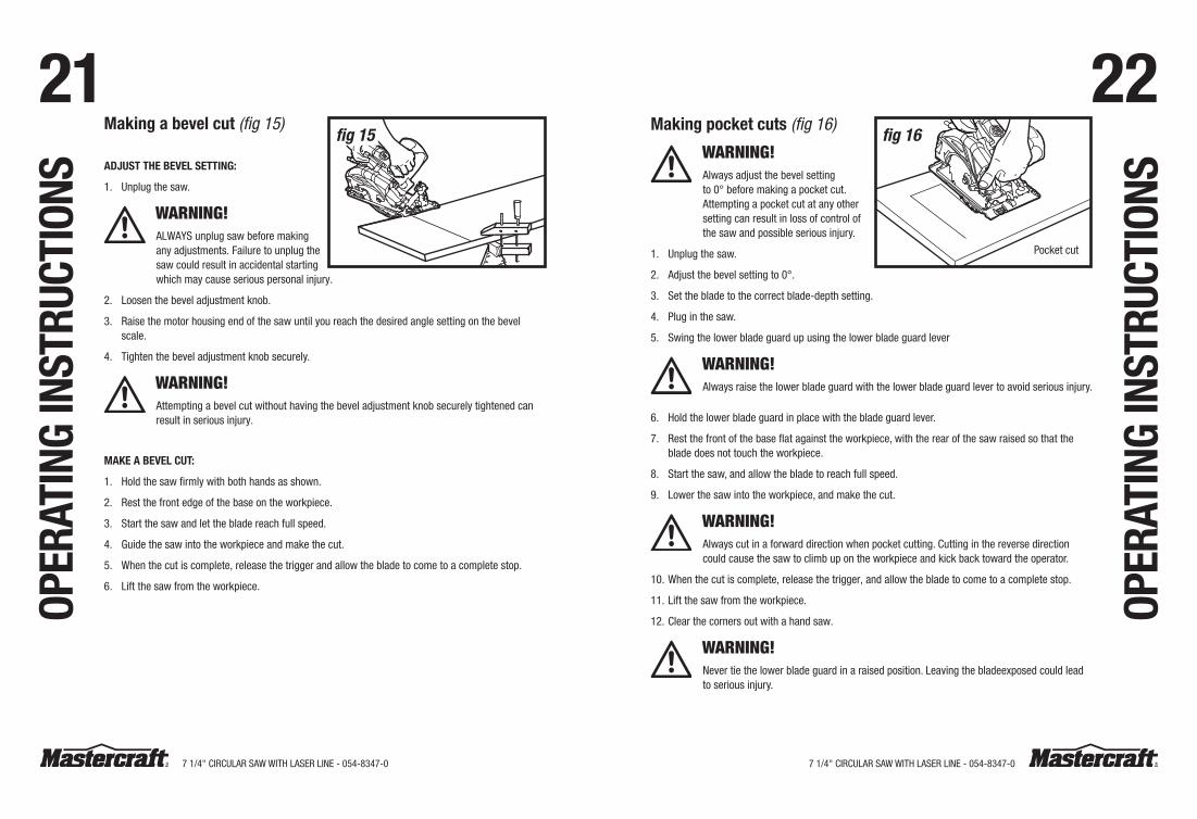
21 22Making a bevel cut (fig 15)
aDjuSt the BeVel SettinG:
1. Unplug the saw.
WARNING! ALwAYS unplug saw before making any adjustments. Failure to unplug the saw could result in accidental starting which may cause serious personal injury.
2. Loosen the bevel adjustment knob.
3. Raise the motor housing end of the saw until you reach the desired angle setting on the bevel scale.
4. Tighten the bevel adjustment knob securely.
WARNING!Attempting a bevel cut without having the bevel adjustment knob securely tightened can result in serious injury.
MaKe a BeVel Cut:
1. hold the saw firmly with both hands as shown.
2. Rest the front edge of the base on the workpiece.
3. Start the saw and let the blade reach full speed.
4. Guide the saw into the workpiece and make the cut.
5. when the cut is complete, release the trigger and allow the blade to come to a complete stop.
6. Lift the saw from the workpiece.
Making pocket cuts (fig 16)
WARNING! Always adjust the bevel setting to 0° before making a pocket cut. Attempting a pocket cut at any other setting can result in loss of control of the saw and possible serious injury.
1. Unplug the saw.
2. Adjust the bevel setting to 0°.
3. Set the blade to the correct blade-depth setting.
4. Plug in the saw.
5. Swing the lower blade guard up using the lower blade guard lever
WARNING!Always raise the lower blade guard with the lower blade guard lever to avoid serious injury.
6. hold the lower blade guard in place with the blade guard lever.
7. Rest the front of the base flat against the workpiece, with the rear of the saw raised so that the blade does not touch the workpiece.
8. Start the saw, and allow the blade to reach full speed.
9. Lower the saw into the workpiece, and make the cut.
WARNING!Always cut in a forward direction when pocket cutting. Cutting in the reverse direction could cause the saw to climb up on the workpiece and kick back toward the operator.
10. when the cut is complete, release the trigger, and allow the blade to come to a complete stop.
11. Lift the saw from the workpiece.
12. Clear the corners out with a hand saw.
WARNING!Never tie the lower blade guard in a raised position. Leaving the bladeexposed could lead to serious injury.
OPer
atin
G in
Stru
CtiO
nS
OPer
atin
G in
Stru
CtiO
nS
fig 16
Pocket cut
fig 15
7 1/4" CIRCULAR SAw wITh LASeR LINe - 054-8347-07 1/4" CIRCULAR SAw wITh LASeR LINe - 054-8347-0
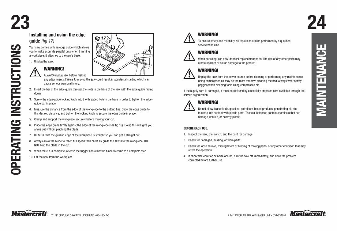
23 24installing and using the edge guide (fig 17)Your saw comes with an edge guide which allows you to make accurate parallel cuts when trimming a workpiece. It attaches to the saw’s base.
1. Unplug the saw.
WARNING!ALwAYS unplug saw before making any adjustments. Failure to unplug the saw could result in accidental starting which can cause serious personal injury.
2. Insert the bar of the edge guide through the slots in the base of the saw with the edge guide facing down.
3. Screw the edge-guide locking knob into the threaded hole in the base in order to tighten the edge-guide bar in place.
4. Measure the distance from the edge of the workpiece to the cutting line. Slide the edge guide to this desired distance, and tighten the locking knob to secure the edge guide in place.
5. Clamp and support the workpiece securely before making your cut.
6. Place the edge guide firmly against the edge of the workpiece (see fig 16). Doing this will give you a true cut without pinching the blade.
7. Be SURe that the guiding edge of the workpiece is straight so you can get a straight cut.
8. Always allow the blade to reach full speed then carefully guide the saw into the workpiece. DO NOT bind the blade in the cut.
9. when the cut is complete, release the trigger and allow the blade to come to a complete stop.
10. Lift the saw from the workpiece.
WARNING!To ensure safety and reliability, all repairs should be performed by a qualified servicetechnician.
WARNING!when servicing, use only identical replacement parts. The use of any other parts may create ahazard or cause damage to the product.
WARNING!Unplug the saw from the power source before cleaning or performing any maintenance.Using compressed air may be the most effective cleaning method. Always wear safety goggles when cleaning tools using compressed air.
If the supply cord is damaged, it must be replaced by a specially prepared cord available through the service organization.
WARNING!Do not allow brake fluids, gasoline, petroleum-based products, penetrating oil, etc. to come into contact with plastic parts. These substances contain chemicals that can damage,weaken, or destroy plastic.
BeFOre eaCh uSe:
1. Inspect the saw, the switch, and the cord for damage.
2. Check for damaged, missing, or worn parts.
3. Check for loose screws, misalignment or binding of moving parts, or any other condition that may affect the operation.
4. If abnormal vibration or noise occurs, turn the saw off immediately, and have the problem corrected before further use.
OPer
atin
G in
Stru
CtiO
nS
Mai
nten
anCe
fig 17
7 1/4" CIRCULAR SAw wITh LASeR LINe - 054-8347-07 1/4" CIRCULAR SAw wITh LASeR LINe - 054-8347-0
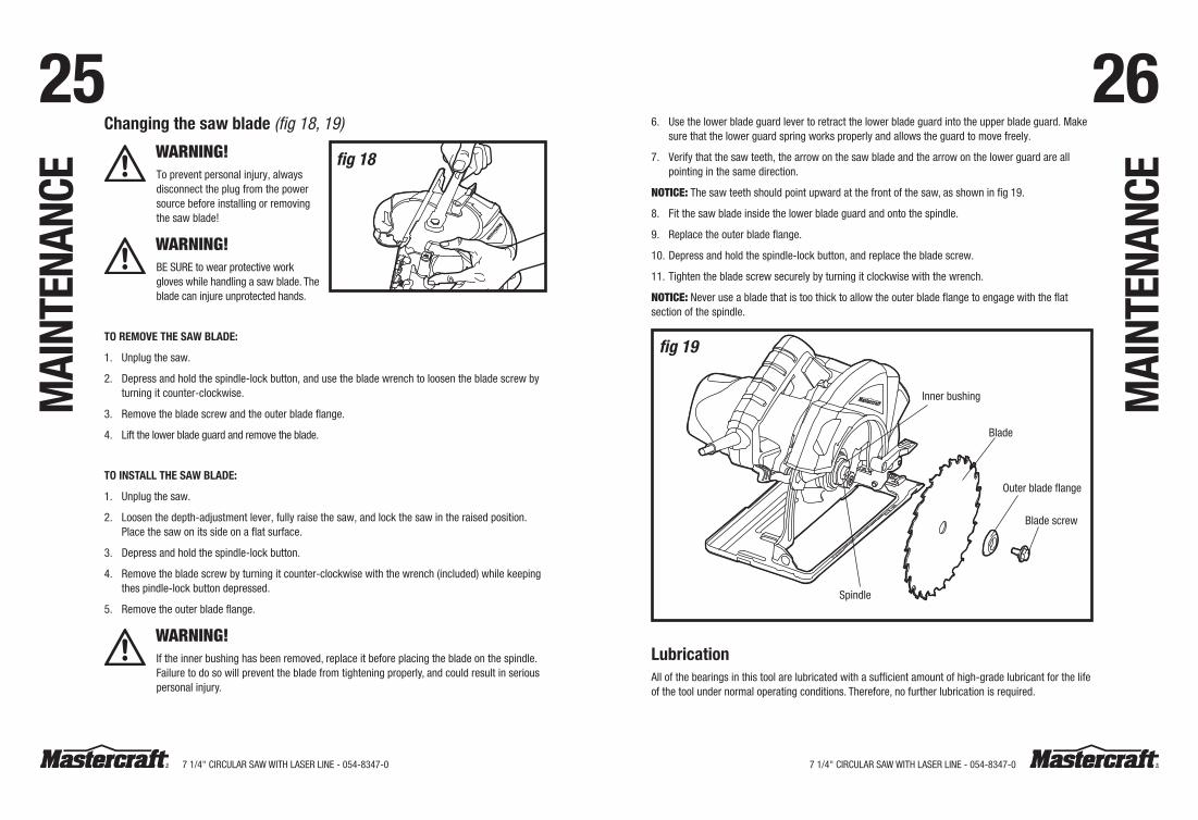
25 26Changing the saw blade (fig 18, 19)
WARNING! To prevent personal injury, always disconnect the plug from the power source before installing or removing the saw blade!
WARNING! Be SURe to wear protective work gloves while handling a saw blade. The blade can injure unprotected hands.
tO reMOVe the Saw BlaDe:
1. Unplug the saw.
2. Depress and hold the spindle-lock button, and use the blade wrench to loosen the blade screw by turning it counter-clockwise.
3. Remove the blade screw and the outer blade flange.
4. Lift the lower blade guard and remove the blade.
tO inStall the Saw BlaDe:
1. Unplug the saw.
2. Loosen the depth-adjustment lever, fully raise the saw, and lock the saw in the raised position.Place the saw on its side on a flat surface.
3. Depress and hold the spindle-lock button.
4. Remove the blade screw by turning it counter-clockwise with the wrench (included) while keeping thes pindle-lock button depressed.
5. Remove the outer blade flange.
WARNING!If the inner bushing has been removed, replace it before placing the blade on the spindle.Failure to do so will prevent the blade from tightening properly, and could result in serious personal injury.
6. Use the lower blade guard lever to retract the lower blade guard into the upper blade guard. Make sure that the lower guard spring works properly and allows the guard to move freely.
7. Verify that the saw teeth, the arrow on the saw blade and the arrow on the lower guard are all pointing in the same direction.
NOTICE:The saw teeth should point upward at the front of the saw, as shown in fig 19.
8. Fit the saw blade inside the lower blade guard and onto the spindle.
9. Replace the outer blade flange.
10. Depress and hold the spindle-lock button, and replace the blade screw.
11. Tighten the blade screw securely by turning it clockwise with the wrench.
NOTICE:Never use a blade that is too thick to allow the outer blade flange to engage with the flat section of the spindle.
fig 19
Spindle
Inner bushing
Blade
Outer blade flange
Blade screw
lubricationAll of the bearings in this tool are lubricated with a sufficient amount of high-grade lubricant for the life of the tool under normal operating conditions. Therefore, no further lubrication is required.
fig 18
Mai
nten
anCe
Mai
nten
anCe
7 1/4" CIRCULAR SAw wITh LASeR LINe - 054-8347-07 1/4" CIRCULAR SAw wITh LASeR LINe - 054-8347-0
27 28PROBLeM POSSIBLe CAUSeS SOLUTIONS
The circular saw does not work
The saw is not connected to a power source
Connect the plug to a power source
The blade does not follow a straight line
The teeth are dull. This is caused by hitting a hard object such as a nail, dulling teeth on one side. The blade tends to cut to the side with the sharpest teeth
Replace the blade
The edge guide or straight edge is not being used
Use an edge guide or straight edge
The blade binds or smokes from friction
The blade is dull Replace the blade
The blade is on backwards Install the blade correctly
The blade is bent Replace the blade
The workpiece is not properly supported Clamp the workpiece correctly and tightly
The incorrect blade is being used Use the correct blade
Iftheproblemremainsunsolvedafterperformingthechecksdescribedabove,callthetoll-freehelplineat1-800-689-9928.
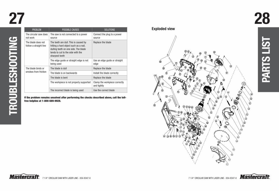
exploded view
trOu
BleS
hOOt
inG
Part
S li
St

7 1/4" CIRCULAR SAw wITh LASeR LINe - 054-8347-07 1/4" CIRCULAR SAw wITh LASeR LINe - 054-8347-0
29 30Pa
rtS
liSt
Part
S li
St
No. PartNo. Description No. PartNo. Description1 3420368000 Upper Guard 31 5650017000 Plain washer
2 5620149000 Flange Screw 32 5610057000 Thread Forming Screw
3 3550222000 Outer Flange 33 2820127000 Lever Set
4 3810073000 Saw Blade 34 3700257000 wave washer
5 3520734000 Inner Flange 35 5630043000 Nut
6 5660026000 Circlips For Shaft 36 5660010000 e Ring
7 3420369000 Lower Guard 37 3121044000 O Ring
8 5610086000 Thread Forming Screw 38 5700014000 Ball Bearing
9 3120558000 Bush 39 2820139000 Spindle Lock Set
10 3420160000 Gear Case Cover 40 2750822000 Rotor
11 5700019000 Ball Bearing 41 5700010000 Ball Bearing
12 3700281000 wave washer 42 3700255000 washer
13 5660023000 Circlips For hole 43 3121054000 Spring
14 3550226000 Gear Shaft 44 5610048000 Tapping Screw
15 5680002000 Plain Key 45 5650007000 Spring washer
16 3550235000 Gear 46 5650005000 Plain washer
17 3660062000 Spring 47 3120552000 wire Clamp
18 3121170000 Plunge Lock Level 48 2740125000 Stator
19 5620039000 Screw 49 5610064000 Thread Forming Screw
20 3700262000 wire holder 50 3120548000 Motor housing
21 3660069000 Spring 51 2800031000 Brush holder
22 3120561000 Lens 52 4960020000 Carbon Brush
23 2820616000 Laser Assembly 53 3121055000 Rubber Insert
24 5650001000 Plain washer 54 3120550000 Rear Cover
25 5650003000 Spring washer 55 5610042000 Tapping Screw
26 5620006000 hexagon Socket Screw 56 3320266000 Left handle
27 3121046000 Stopper 57 2822097000 Transformer & Switch
Assembly
28 5700041000 Porous Bearing 58 3120554000 Cap
29 3420367000 Gear Case 59 4870091000 Switch
30 5620150000 Screw 60 4930432000 Connecter
Ifanypartsaremissingordamaged,orifyouhaveanyquestions,pleasecalltheToll-freeHelpline,at1-800-689-9928.
No. PartNo. Description No. PartNo. Description61 5610031000 Tapping Screw 73 3400010000 wing Nut
62 3700367000 Cord Anchorage 74 5650016000 Plain washer
63 5610063000 Thread Forming Screw 75 3120562000 Line Guide
64 3121047000 Cord Guard 76 5670008000 Spring Pin
65 4810002000 Power Cord & Plug 77 3660071000 Spring
66 2490136000 Nylon String 78 3400011000 wing Bolt
67 3320267000 Right handle 79 5640019000 Square Neck Bolt
68 2820764000 Internal wire Assembly 80 5620044000 Screw
69 2820772000 Internal wire Assembly 81 5630001000 hexagon Nut
70 2822076000 Internal wire Assembly 82 3700865000 wrench
71 2822027000 Base Plate Set 83 3700663000 Rip Fence
72 5620038000 Screw
Ifanypartsaremissingordamaged,orifyouhaveanyquestions,pleasecalltheToll-freeHelpline,at1-800-689-9928.
7 1/4" CIRCULAR SAw wITh LASeR LINe - 054-8347-07 1/4" CIRCULAR SAw wITh LASeR LINe - 054-8347-0
31 32
This Mastercraft product is guaranteed for a period of 3yearsfromthedateoforiginalretailpurchase against defects in workmanship and materials, except for the following components:
a) Component A: Batteries, chargers and carrying case, which are guaranteed for a period of 2 years from the date of original retail purchase against defects in workmanship and materials;
b) Component B: Accessories, which are guaranteed for a period of 1-year from the date of original retail purchase against defects in workmanship and materials.
Subject to the conditions and limitations described below, this product, if returned to us with proof of purchase within the stated warranty period and if covered under this warranty, will be repaired or replaced (with the same model, or one of equal value or specification), at our option. we will bear the cost of any repair or replacement and any costs of labour relating thereto.
these warranties are subject to the following conditions and limitations:a) a bill of sale verifying the purchase and purchase date must be provided;
b) this warranty will not apply to any product or part thereof which is worn or broken or which has become inoperative due to abuse, misuse, accidental damage, neglect or lack of proper installation, operation or maintenance (as outlined in the applicable owner’s manual or operating instructions) or which is being used for industrial, professional, commercial or rental purposes;
c) this warranty will not apply to normal wear and tear or to expendable parts or accessories that may be supplied with the product that are expected to become inoperative or unusable after a seasonable period of use;
d) this warranty will not apply to routine maintenance and consumable items such as, but not limited to, fuel, lubricants, vacuum bags, blades, belts, sandpaper, bits, fluids, tune-ups or adjustments;
war
rant
Ye) this warranty will not apply where damage is caused by repairs made or attempted by others (i.e.
persons not authorized by the manufacturer);
f) this warranty will not apply to any product that was sold to the original purchaser as a reconditioned or refurbished product (unless otherwise specified in writing);
g) this warranty will not apply to any product or part thereof if any part from another manufacturer is installed therein or any repairs or alterations have been made or attempted by unauthorized persons;
h) this warranty will not apply to normal deterioration of the exterior finish, such as, but not limited to, scratches, dents, paint chips, or to any corrosion or discolouring by heat, abrasive and chemical cleaners; and
i) this warranty will not apply to component parts sold by and identified as the product of another company, which shall be covered under the product manufacturer’s warranty, if any.
additional limitationsThis warranty applies only to the original purchaser and may not be transferred. Neither the retailer nor the manufacturer shall be liable for any other expense, loss or damage, including, without limitation, any indirect, incidental, consequential or exemplary damages arising in connection with the sale, use or inability to use this product.
notice to ConsumerThis warranty gives you specific legal rights, and you may have other rights, which may vary from province to province. The provisions contained in this warranty are not intended to limit, modify, take away from, disclaim or exclude any statutory warranties set forth in any applicable provincial or federal legislation.
war
rant
Y