Embed Size (px)
Citation preview

MT-00E-001-B
Applicable Models:
STP-603/1003 series
STP-H301/H451 series
STP-H803/H1303 series
STP-A803/A1303 series
STP-A1603 series
STP-A2203 series
STP-A2503/A3003 series
STP-A2803/A3503 series
STP-F2203 series
STP-XH2603P/XH3203P series
STP-XA2703/XA3203 series
STP-XA4503 series
STP-XW3503 series
STP Series Turbomolecular Pumps Generic Instruction Manual
Instruction Manual (A)
STP pump consists of the three-volumed Instruction Manuals. Instruction Manual (A): (This Instruction Manual)
STP pump generic Instruction Manual
Instruction Manual (B): STP pump specific information Instruction Manual (C): STP control unit Instruction Manual
Copyright 2010 Edwards Japan Limited. All rights reserved. Printed in Japan.
The description of this product consists of the three-volumed Instruction Manuals. Read through each Instruction Manual before operation. The separate volume contents of each description are as follows:
Instruction Manual (A)
STP pump generic Instruction Manual:
• Introduction
• Installation of the STP pump
• Installation of the STP control unit
• Operation
• Safety functions
• Maintenance and inspection
• Storage and disposal
• Service, Spares and accessories
Instruction Manual (B)
STP pump specific information:
• Technical data
• How to Secure the STP pump
• Temperature Management System (TMS)
Instruction Manual (C)
STP control unit Instruction Manual:
• Introduction
• Technical data
• Installation
• Operation
• Serial communication protocol
• STP-Link (except for SCU-750)
• Maintenance
• Storage, transportation and disposal
• Service, spares, and accessories
Keep the manuals in an easily accessible location.
STP Series Turbomolecular Pump
March 10 i Issue 1-b
PAGEi CONTENTS
Section Title Page
1 INTRODUCTION 1
1.1 Scope and definitions 1 1.2 Applied standards 2 1.3 Limited warranty 2 1.3.1 Warranty period 2 1.3.2 Item warranted 2 1.3.3 Disclaimer 3 1.3.4 Spare parts 3 1.4 Precautions for safe operation of the STP pump 4 1.4.1 Usable gases 4 1.5 Maintenance and inspection precautions 5 1.6 Labels 5 1.7 Operation principle of the STP pump 8 1.8 Temperature management system 9 1.9 Name of the STP pump 10
2 INSTALLATION OF THE STP PUMP 13
2.1 Precautions before installation 13 2.1.1 Operating environment 13 2.1.2 Installation area 14 2.1.3 Bench 15 2.2 Unpacking 16 2.2.1 Unpacking the STP pump 16 2.3 How to install the STP pump 18 2.3.1 Cleaning the seal 20 2.3.2 STP pump installation positions 21 2.3.3 Secure the STP pump 22 2.3.4 Precautions of vacuum piping 22 2.3.5 Vacuum piping method 23 2.3.6 Connecting the purge port 24 2.3.7 Connecting the water cooling pipe 24 2.3.8 Attaching a baking heater 25 2.3.9 Installation of the air cooling unit 25 2.3.10 Installation of the TMS unit 26
3 INSTALLATION OF THE STP CONTROL UNIT 27
3.1 STP control unit 27 3.1.1 SCU-800 27 3.1.2 SCU-750 28 3.1.3 SCU-1400 28 3.1.4 SCU-1500 29 3.1.5 SCU-1600 29 3.2 Cable connection 30 3.2.1 STP connection cable 30 3.2.2 Power cable 31 3.3 How to connect the cables 32

STP Series Turbomolecular Pump
March 10 ii Issue 1-b
PAGE ii
CONTENTS Section Title Page
4 OPERATION 35
4.1 Before starting the STP pump 35 4.1.1 Tuning 35 4.1.2 Operation of vacuum system 36 4.2 Pump operation 36 4.2.1 LED indication during operation 36 4.2.2 Starting the STP pump after a safety function operates 37 4.3 Gas pumping, cooling and baking the STP pump 37 4.3.1 Gas pumping 37 4.3.2 How to introduce a purge gas 38 4.4 Cooling the STP pump 38 4.4.1 Water-cooling method 38 4.4.2 Air-cooling method 39 4.5 Baking the STP pump 39 4.6 How to use the TMS unit 40 4.6.1 Parameter set mode 40 4.6.2 Starting/stopping the TMS unit 40 4.6.3 Temperature control 40
5 SAFETY FUNCTIONS 41
5.1 Safety functions 41 5.1.1 Power failure 41 5.1.2 Operation after a power recovery 41 5.1.3 Abnormal state of magnetic bearing 42 5.1.4 Excessive vibration 42 5.1.5 Motor driver overload 42 5.1.6 Overheating inside the STP pump 42 5.1.7 Overheating inside the STP control unit 43 5.1.8 Overspeed 43 5.1.9 Abnormality/Error in the TMS unit (for use with the TMS unit) 43 5.1.10 Failure of the air-cooling fan (for SCU-800 only) 43
6 MAINTENANCE AND INSPECTION 45
6.1 Maintenance and inspection 45 6.2 Cleaning 46 6.3 Inspecting the deposit 46 6.4 Overhaul 47 6.5 Transporting for repair or overhaul 48
7 STORAGE AND DISPOSAL 49
7.1 Storage of the STP pump 49 7.2 Disposal 50

STP Series Turbomolecular Pump
March 10 iii Issue 1-b
PAGEiii
CONTENTS Section Title Page
8 SERVICE, SPARES AND ACCESSORIES 51
8.1 Introduction 51 8.2 Service 51 8.3 Spares 51 8.4 Accessories 52

STP Series Turbomolecular Pump
March 10 iv Issue 1-b
PAGE iv ILLUSTRATIONS
Figure Title Page
1 STP pump installation warning label 5 2 Hot surface warning label 5 3 Heavy product caution label 6 4 Connector caution label 6 5 Caution label 6 6 TMS heater surface caution label 7 7 Rotation instruction label 7 8 Cross sectional view of the STP pump 8 9 Configuration of the STP pump (Typical pump model) 10 10 Example of lifting the STP pump 16 11 Example of lifting the STP pump (horizontal positioning) 17 12 Installation of the STP pump to the vacuum equipment 19 13 STP pump installation positions 21 14 Positions of the outlet port on the horizontally
or slanted installed STP pump 21 15 Positions of the cooling water port and baking heater 24 16 SCU-800 27 17 SCU-750 28 18 SCU-1400 28 19 SCU-1500 29 20 SCU-1600 29 21 SCU-750/SCU-800 STP connection cable 30 22 SCU-1400/SCU-1500/SCU-1600 STP connection cable 30 23 SCU-750 power cable 31 24 SCU-800 power cable 31 25 SCU-1400/SCU-1500/SCU-1600 power cable 31
STP Series Turbomolecular Pump
March 10 1 Issue 1-b
INTR
OD
UC
TION
1 1 INTRODUCTION 1.1 Scope and definitions
This manual provides installation, operation and maintenance instructions for the Edwards Turbomolecular Pump (abbreviated to "STP pump" throughout this manual). In this manual, the control unit for the turbomolecular pump is referred to as the "STP control unit". You must use the STP pump as specified in this manual.
The procedures in this manual must be followed before you install, operate and maintain the STP pump. Important safety information is highlighted as WARNING and CAUTION instructions; these instructions are mandatory. The use of WARNINGS and CAUTIONS is defined below:
WARNING
Warnings are given where failure to observe the instruction could result in serious injury or death to people.
CAUTION
Cautions are given where failure to observe the instruction could result minor personal injury in
damage to the equipment, associated equipment and/or process. Note: Items you must follow during operation and maintenance.
Throughout this manual, page, figure and table numbers are sequential.
The units used throughout this manual conform to the SI international system of units of measurement; US equivalent units of measurement are also given.
The following IEC warning labels/symbols appear on the STP Pump Instruction Manual:
Warning - refer to accompanying documentation.
Warning - risk of electric shock.
Warning - heavy object.
Note: An alarm function is incorporated into this STP series. Alarm and cautionary messages are
displayed on the LCD of the STP control unit. Note that the words "WARNING" and "CAUTION" displayed on the LCD indicate the need for overhaul of the pump or precautions during the operation. They do not have the same meaning as the much more serious symbols for "WARNING" and "CAUTION" used in the instruction manual.

STP Series Turbomolecular Pump
March 10 2 Issue 1-b
INTR
OD
UC
TION
1
1.2 Applied standards
The STP pump conforms to the following directives and standards:
1. Applied Directives
• EC Machinery Directive
• EC Electromagnetic Compatibility Directive
• EC Low Voltage Directive
2. Applied Standards
• EN1012-2
• EN61010-1
• EN61326 (class A)
• EN61000-6-2
3. Applied Standards (Only some model. Contact Edwards about recognized model.)
• UL61010-1, 2nd Edition (Electrical Equipment for Laboratory Use; Part 1: General Requirements)
1.3 Limited warranty
This WARRANTY applies to the customer to whom Edwards has delivered this product.
1.3.1 Warranty period
Edwards warrants this product against defects for a period of two (2) years from the date of delivery or during the period specified in the agreement made by and between the customer and Edwards.
1.3.2 Item warranted
1. This warranty applies only to the product delivered from Edwards to the customer.
2. If any defect is found during this period, Edwards will, at its option, repair or recondition the product free of charge. The costs for repair or replacement of the product after the warranty period has passed will be at your own charge.

STP Series Turbomolecular Pump
March 10 3 Issue 1-b
INTR
OD
UC
TION
1
1.3.3 Disclaimer
Edwards makes no warranty with respect to any damage occurred due to any of the following during the warranty period:
1. Handling, operation or maintenance other than that specified herein.
2. Failure to follow any of the warnings or cautions enumerated in this manual.
3. Installation, operation or maintenance using parts which are not specified by Edwards.
4. Maintenance personnel other than those authorized by Edwards or Service office have disassembled, reconditioned, or tampered the product.
5. Defect resulting from the not-specified use of the product.
6. When the product is used under special conditions without obtaining the written consent of Edwards (particular gases, strong magnetic field and the radiation are added to the product).
7. Defect resulting from deposit.
8. Water cooling system defect resulting from water quality used.
9. Defect resulting from the installation of the product (exclude the installation by authorized personnel).
10. Deterioration in the external because of use (discoloration, scratches and so forth).
11. Product damage occurred during transport or other factors not attributable to Edwards.
12. Product breakage or damage due to natural disasters, fire or other external factors.
13. Deterioration in the basic performance due to the use of the product beyond limits of the use.
14. Any direct, incidental or consequential damage resulting from the use of the product.
15. When continuously operated without overhaul after the WARNING indication ("WARNING" message) on the LCD.
16. Overhaul and replacement of maintenance parts.
1.3.4 Spare parts
• Touch down bearing. (Touch down bearing should be replaced at Edwards, contact Edwards).
• Heater

STP Series Turbomolecular Pump
March 10 4 Issue 1-b
INTR
OD
UC
TION
1
1.4 Precautions for safe operation of the STP pump
1.4.1 Usable gases
1. Chlorine or fluorine system gases can be used in corrosion resistant pumps. When you use the following gases, contact Edwards.
• Gases including alkaline metals except Li gas.
• Gases including Ga, Hg, In, or Sn.
• HBr gas.
2. Non-corrosion resistant pump cannot use the above gases including chlorine and fluorine system gases.
WARNING
To prevent an accident, confirm the characteristics of gases to be used, referring to the Material Safety Data Sheet (MSDS) you obtain from the gas supplier, and, keep MSDS
and a safety advice of gas supplier.
WARNING
Warn of the danger of the gas with the warning label when the use gas is hazardous WARNINGchemical material.
WARNING
Secure safety by wearing personal protective equipment when using the gas which might influence damage health. In addition, take appropriate measure for depending
upon the properties of the gas to be used.
CAUTION
NEVER use any gas that is not specified as usable in this Manual. The use of such gas may CAUTION corrode the STP pump and damage it.
CAUTION
Introduce a dry N2 gas (purge gas) to protect the inside of the STP pump when using reactive or
corrosive gas. The use of reactive or corrosive gas may result in product damage.
CAUTION
Cool the STP pump to prevent the STP pump from overheating when pumping gases.

STP Series Turbomolecular Pump
March 10 5 Issue 1-b
INTR
OD
UC
TION
1
1.5 Maintenance and inspection precautions
Perform any maintenance or inspection of the STP pump, following Section 6, "MAINTENANCE AND INSPECTION".
1.6 Labels
The following labels are affixed to the STP pump. Read the contents of the labels before operation.
1. STP pump installation warning label
This label describes installation of the STP pump. Install the STP pump according to the precautions. Install the STP pump according to the precautions of Section 2, "INSTALLATION OF THE STP PUMP".
Figure 1 - STP pump installation warning label
2. Hot surface warning label
This label instructs operators so as not to touch the hot surface of the STP pump and the TMS unit. The TMS unit specification may lead to a considerable rise in temperatures outside the STP pump. (only with TMS unit)
Figure 2 - Hot surface warning label

STP Series Turbomolecular Pump
March 10 6 Issue 1-b
INTR
OD
UC
TION
1
3. Heavy product caution label
This label is affixed to the product with a weight of 18 kg or more. Follow the precautions of Section 2.2, "Unpacking" so as not to cause any accident during handling.
Figure 3 - Heavy product caution label
4. Connector caution label
This label describes lock of the connector. This label instructs operators to prevent the connectors from being disconnected while the STP pump is in operation.
Figure 4 - Connector caution label
5. STP pump/control unit caution label
This label describes precautions for operating the STP pump. Follow these precautions.
Figure 5 - Caution label

STP Series Turbomolecular Pump
March 10 7 Issue 1-b
INTR
OD
UC
TION
1
6. TMS heater caution label
This label instructs operators so as not to remove the TMS heater from the STP pump. (only with TMS unit)
Figure 6 - TMS heater caution label
7. Rotational direction instruction label
This label describes the rotational direction of the STP pump. The STP pump rotates in this direction.
Figure 7 - Rotation instruction label

STP Series Turbomolecular Pump
March 10 8 Issue 1-b
INTR
OD
UC
TION
1
1.7 Operation principle of the STP pump
The STP series pump is a series of a magnetically-levitated turbomolecular pumps, each with the following features:
• Oil free
• Low vibration
• High reliability
1. Rotor blade 5. Axial sensor
2. Stator blade 6. Axial electromagnet
3. Radial sensor 7. Touch down bearing
4. Radial electromagnet
Figure 8 - Cross sectional view of the STP pump

STP Series Turbomolecular Pump
March 10 9 Issue 1-b
INTR
OD
UC
TION
1
The STP pump (Figure 8) is configured so that rotor blade (1) and stator blade (2) are aligned alternately in the axial direction. Gas molecules are pumped from the inlet port to the outlet port by the high speed rotation of the rotor.
The STP pump is configured so that rotor blade (1) and stator blade (2) are aligned alternately in the axial direction
The rotor blade (1) is supported by the magnetic bearing without mechanical contact. Therefore, the STP pump requires no lubrication oil unlike conventional turbomolecular pumps using ball bearings.
The magnetic bearing consists of 5 pairs of active magnetic bearings. The rotor is supported in the radial direction by 4 pairs of radial direction active magnetic bearings that consist of radial sensor (3) and radial electromagnet (4). A pair of axial direction active magnetic bearings consists of axial sensor (5) and axial electromagnet (6) to support the rotor in the axial direction. Because the rotor is supported without mechanical contact, it can rotate at low vibration.
There is less heat generated from magnetic bearings because there is no friction. Therefore, the STP pump requires no cooling. However, the STP pump does require water-cooling or air-cooling during baking and gas pumping. Taking into consideration an unexpected failure of magnetic bearings, touch down bearings (7) coated with solid lubrication have been installed. They do not contact with the rotor during the rated operation.
A radial sensor, an axial sensor, a rotation sensor and a temperature sensor always monitor the magnetic bearing as well as the rotor. If an abnormality/error occurs, the rotor will stop.
1.8 Temperature management system
The Temperature Management System (TMS) maintains the temperature of the turbomolecular pump by monitoring the temperature using a thermistor in the base of the turbomolecular pump, and performing the TMS valve and base heater ON/OFF control.

STP Series Turbomolecular Pump
March 10 10 Issue 1-b
INTR
OD
UC
TION
1
1.9 Name of the STP pump
1. Inlet port flange 4. Outlet port flange
2. TMS sensor connector 5. STP connector
3. Cooling water port 6. Purge port
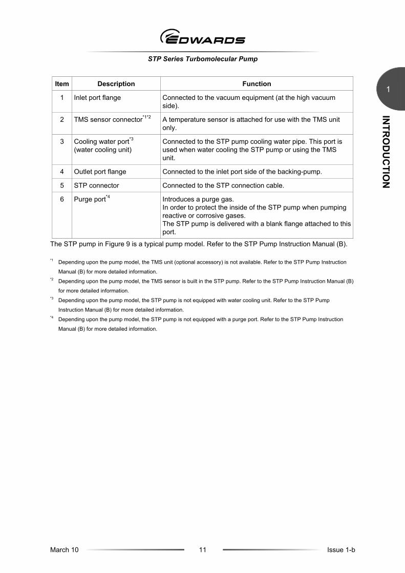
Figure 9 - Configuration of the STP pump (Typical pump model)
STP Series Turbomolecular Pump
March 10 11 Issue 1-b
INTR
OD
UC
TION
1
Item Description Function
1 Inlet port flange Connected to the vacuum equipment (at the high vacuum side).
2 TMS sensor connector*1*2 A temperature sensor is attached for use with the TMS unit only.
3 Cooling water port*3
(water cooling unit) Connected to the STP pump cooling water pipe. This port is used when water cooling the STP pump or using the TMS unit.
4 Outlet port flange Connected to the inlet port side of the backing-pump.
5 STP connector Connected to the STP connection cable.
6 Purge port*4 Introduces a purge gas. In order to protect the inside of the STP pump when pumping reactive or corrosive gases. The STP pump is delivered with a blank flange attached to this port.
The STP pump in Figure 9 is a typical pump model. Refer to the STP Pump Instruction Manual (B).
*1 Depending upon the pump model, the TMS unit (optional accessory) is not available. Refer to the STP Pump Instruction
Manual (B) for more detailed information. *2 Depending upon the pump model, the TMS sensor is built in the STP pump. Refer to the STP Pump Instruction Manual (B)
for more detailed information. *3 Depending upon the pump model, the STP pump is not equipped with water cooling unit. Refer to the STP Pump
Instruction Manual (B) for more detailed information. *4 Depending upon the pump model, the STP pump is not equipped with a purge port. Refer to the STP Pump Instruction
Manual (B) for more detailed information.

STP Series Turbomolecular Pump
March 10 12 Issue 1-b
INTR
OD
UC
TION
1
This page intentionally blank

STP Series Turbomolecular Pump
March 10 13 Issue 1-b
INSTA
LLATIO
N
2 2 INSTALLATION OF THE STP PUMP 2.1 Precautions before installation
2.1.1 Operating environment
WARNING
To prevent an accident, confirm the characteristics of gases to be used, referring to the Material Safety Data Sheet (MSDS) you obtain from the gas supplier, and, keep
MSDS and a safety advice of gas supplier.
WARNING
Take measures according to MSDS to prevent an accident when using toxic, reactive or combustible gases. Dilute the gas to be used with the inert gas controlled if necessary. And, take measures according to MSDS to prevent an accident caused
by exhaust gas.
CAUTION
If the STP pump is to be used in an area with radiation, contact Edwards.
CAUTION
Chlorine or fluorine system gases can be used in corrosion resistant pumps. When you use the
following gases, contact Edwards:
• Gases including alkaline metals except Li gas. • Gases including Ga, Hg, In, or Sn. • HBr gas.
Non-corrosion resistant pump cannot use the above gases including chlorine and fluorine system gases.

STP Series Turbomolecular Pump
March 10 14 Issue 1-b
INSTA
LLATIO
N
2
The STP pump should be installed in an area which meets the following requirements:
Ambient temperature 0 to 40 °C (32 to 104 °F)
Ambient relative humidity 30 to 95% (no dew condensing)
Environment • An area free of externally applied mechanical shock.
• A place free of a heat source (Keep clear of the heat source or attach a thermal shield plate).
• A place free of a strong magnetic field (Range: up to 15 mT (150 G) in the axial direction, and up to 3 mT (30 G) in the radial direction with respect to the rotational axis of the STP pump).
• A place free of a strong electric field.
• A place free of exposure to radiation.
• No discharge of high voltage (more than 500 V) (If more than 500V is discharged, contact Edwards).
STP pump installation equipment conditions
Install the STP pump securely so that foreign materials cannot fall into the STP pump (Ex.: Si wafers or samples are positioned above the STP pump) (To prevent foreign materials from falling into the STP pump, design a shield plate with large conductance).
2.1.2 Installation area
Leave enough space for the following in addition to that for the STP pump:
• Space for maintenance and inspection. • Space for connecting cables.
CAUTION
The minimum bending radius of the STP connection cable is 100 mm (see the STP Pump Instruction Manual (B), "External Appearance of the STP pump" [bending dimensions of the
connection cable]). DO NOT bend the cables excessively and beware of any obstacles when installing the STP pump.
In addition, leave enough space to install other cables without bending them excessively.
Note: The L-type STP connection cable is also offered. Contact Edwards if necessary.

STP Series Turbomolecular Pump
March 10 15 Issue 1-b
INSTA
LLATIO
N
2
2.1.3 Bench
A bench must be prepared by the customer to secure the STP pump. The shape and size of the bench differ depending upon the type of STP pump. (see "HOW TO SECURE THE STP PUMP" in the STP Pump Instruction Manual (B))
WARNING
Obey the safety instructions given below and take note of appropriate precautions. If you do not, you can cause injury to people and damage to equipment.
WARNING
The STP pump is provided with a high-speed rotor. Any internal abnormality/error may result in a jump in rotational torque leading to personal injury or peripheral
equipment damage.
WARNING
Design and secure the bench for the STP pump so that it can withstand the maximum torque generated due to the occurrence of an abnormality/error. Refer to "HOW TO SECURE THE STP PUMP" in the STP Pump Instruction Manual (B) for
abnormal torque.
CAUTION
Secure the customer-prepared bench and the vacuum equipment on the floor or peripheral
equipment and other equipment in accordance with the customer application. NEVER move them while the STP pump is in operation.
Confirm the dimensions by the external appearance of the STP pump when designing the bench.
The bolt may not be able to be inserted from the lower side of the inlet port according to the shape of the inlet port flange.
Note: When the external appearance of the STP pump is not in the manual, contact Edwards.

STP Series Turbomolecular Pump
March 10 16 Issue 1-b
INSTA
LLATIO
N
2
2.2 Unpacking
2.2.1 Unpacking the STP pump
Check outer package for damage and that the delivery note corresponds to the purchase order.
Note: It is recommended to keep the packaging materials, such as the corrugated fiberboard container and cushioning material for possible reuse. If the STP pump is damaged, return it in its original package and contact Edwards or their distributor.
WARNING
The STP pumps are heavy products. Observe national laws/regulations, safety standards and manufacturers instructions when lifting the STP pump. Lifting devices must be used when lifting or moving the STP pump.
The STP pumps are heavy products. (Refer to "TECHNICAL DATA" in the STP Pump Instruction Manual (B) for the mass of the STP pump) Use a crane or other appropriate means sufficient enough to withstand the load when lifting the STP pump of 18kg or more.
Lift the STP pump with an eyebolt or a similar tool that uses the fitting hole attached to the inlet port flange. When lifting the pump, use 2 or more ropes. (see Figure 10) A crane, eyebolts, and rope due to lifting operations should withstand the load of three times or more the weight of the STP pump. Use an eyebolt which confirms to ISO03266.
Lift the STP pump with the aid of a suspension tool under the base when installing the pump without fitting hole.
Always lift the STP pump in stable places free of excessive shock or vibration to prevent it from shaking or dropping.
Care should be taken not to scratch the flange of the STP pump. Before installing the STP pump, check that there are no scratches on the surface.
Figure 10 - Example of lifting the STP pump

STP Series Turbomolecular Pump
March 10 17 Issue 1-b
INSTA
LLATIO
N
2
When installing the STP pump horizontally using a crane or other appropriate, support pump casing, or pump base (see Figure 11). DO NOT apply face on convex parts, such as the outlet port or connectors by ropes. Doing so may the pump to fall, or deform and damage the parts.
A crane and rope due to lifting operations should withstand the load of three times or more the weight of the STP pump. When lifting the pump, use 2 or more ropes.
Figure 11 - Example of lifting the STP pump (horizontal positioning)
When jacking up the bottom of the STP pump, a device due to jacking up the STP pump should withstand the load of three times or more the weight of the STP pump.

STP Series Turbomolecular Pump
March 10 18 Issue 1-b
INSTA
LLATIO
N
2
2.3 How to install the STP pump
Install the STP pump to the vacuum equipment as shown in Figure 12.
WARNING
An appropriate enclosure or a barrier which cannot be removed without using a tool should be provided to prevent an operator from accessing the connection cables
between the STP pump and its connectors provided.
WARNING
When installing the STP pump and connecting/disconnecting cables, always power off the primary power (switch the MAIN POWER to "OFF") and isolate
(Lockout/Tagout) the electrical energy source, water and gas, and other energy sources on the vacuum equipment. Failure to do so may result in the inadvertent rotation of the STP pump which may result in an accident, an electric shock or
damage to equipment. Moreover, an accident caused by water leaks or gas leak may occur.
CAUTION
Use a lifter or the like when installing the STP pump to the vacuum equipment. Failure to do so might hurt your back or cause injuries due to occurrence of an accident such as fall.
A supportive device such as lifter to installing the STP pump should withstand the load of three times or more the weight of the STP pump.

STP Series Turbomolecular Pump
March 10 19 Issue 1-b
INSTA
LLATIO
N
2
1. STP control unit 4. STP connection cable 7. Outlet port
2. Power cable 5. (Vacuum equipment) *3 8. (Vacuum valve) *3
3. TMS connection cable 6. Inlet port flange 9. (Backing-pump [dry pump, and other])*3
*1 The STP pump can be installed through the damper (optional accessory). *2 The TMS unit is an optional accessory. Refer to the STP Pump Instruction Manual (B) for more detailed information.
*3 The equipment and part within the parentheses must be prepared by the customer.
Figure 12 - Installation of the STP pump to the vacuum equipment
23
1
4
5
6
7
8
9
*1
*2
STP Series Turbomolecular Pump
March 10 20 Issue 1-b
INSTA
LLATIO
N
2
2.3.1 Cleaning the seal
WARNING
The wipes used to clean the flange of the pump might become hazardous waste depending upon the solvent (alcohol). Dispose of the contaminated wipes
appropriately according to the regulations of each national and/or local government.
WARNING
Obey the safety instructions given below and take note of appropriate precautions when disposing of hazardous waste. If you do not, you can cause injury to people
and damage to equipment.
CAUTION
A splinter shield is attached to the inlet port flange to prevent foreign materials from falling into the STP pump. Always leave the splinter shield attached during operation.
CAUTION
ALWAYS install the STP pump in such a manner that foreign materials cannot easily fall into it. Foreign materials falling into the STP pump through the splinter shield may result in product
damage.
Inspect the seals of inlet and outlet port flanges for dirt or oil spots before installing the STP pump to the vacuum equipment.
Take the following measures for cleaning the seals:
• Clean off with a pure gas. • Wipe with proper solvent (such as alcohol).
The splinter shield cannot perfectly prevent foreign materials from falling into the STP pump. ALWAYS install the STP pump in such a manner that foreign materials cannot easily fall into it (for example, Si wafers or samples are positioned above the STP pump). If this is not possible, always attach a shield plate with sufficient conductance above the STP pump to prevent foreign materials from falling into it. Foreign materials falling into the STP pump through the splinter shield may result in product damage.
Take care not to scratch the flange of the STP pump. Check whether or not there are scratches on the surface, before installing the STP pump. If unsatisfactory, contact Edwards.

STP Series Turbomolecular Pump
March 10 21 Issue 1-b
INSTA
LLATIO
N
2
2.3.2 STP pump installation positions
The STP pump can be installed vertically, horizontally, upside-down and/or slanted. (Depending upon the pump model, the STP pump cannot be installed in some positions. Refer to "TECHNICAL DATA" in the STP Pump Instruction Manual (B).)
1. Vacuum equipment 4. Slanted
2. Upside-down 5. Vertical
3. Horizontal
Figure 13 - STP pump installation positions
When installing the STP pump in a horizontal or slanted position, it is recommended to install it so that the direction of the outlet port is on a vertical or horizontal plane in the direction of the gravity. This makes it possible to reduce the load on the magnetic bearing and the heat generated by the STP pump.
* Direction of gravity
Figure 14 - Positions of the outlet port on the horizontally or slanted installed STP pump
*

STP Series Turbomolecular Pump
March 10 22 Issue 1-b
INSTA
LLATIO
N
2
2.3.3 Secure the STP pump
WARNING
The STP pump is provided with a high-speed rotor. Any internal abnormality/error may result in a jump in rotational torque leading to personal injury or peripheral
equipment damage.
The STP pump is provided with a high-speed rotor. The worst-case failure may result in a jump in rotational torque leading to personal injury or peripheral equipment damage.
The method of securing the STP pump will depend on the STP pump model and its installation requirements. Secure the STP pump to the vacuum equipment as "HOW TO SECURE THE STP PUMP" in the STP Pump Instruction Manual (B).
The STP pump is a component system when installing to the semiconductor equipment. Consider the following when installing to the semiconductor equipment.
• Confirm that electric resistance value between the STP pump and vacuum equipment is set to 0.1 Ω or less after securing the STP pump to the vacuum equipment.
2.3.4 Precautions of vacuum piping
CAUTION
DO NOT open the STP pump through the flange to atmospheric air while the STP pump is running. If atmospheric air flows into the STP pump, it may not function normally.
Depending upon the type of the backing-pump used, atmospheric air may reverse flow into the STP pump when the backing-pump stops.
Attach a vacuum valve to the middle of the piping between the STP pump outlet port flange and the backing-pump, and close the vacuum valve when the backing-pump stops.
In order to let the STP pump bring its performance into full play, follow the precautions below:
1. Be careful not to scratch the flange of the STP pump and vacuum equipments. Before installing the STP pump, check whether or not there are scratches on the surface.
2. Use steel or aluminum tubes with a low gas loss to connect the vacuum equipment to the STP pump.
3. Take measures for minimizing leakage. It is also necessary to degrease the tubes as regularly as possible to keep the gas loss as low as possible.
4. There is a recommended backing-pump of pumping speed. (Refer to "TECHNICAL DATA" in the STP Pump Instruction Manual (B). However, the pressure at the inlet and outlet ports varies with the flow rate of gas, capacity of the vacuum equipment, length and material of the piping. Select a backing-pump in accordance with the capacity and starting method (simultaneous starting, starting after generating roughing vacuum) suitable for the vacuum equipment you use.
STP Series Turbomolecular Pump
March 10 23 Issue 1-b
INSTA
LLATIO
N
2
5. Connect the STP pump and the backing-pump using stainless steel or aluminum alloy tubing, flexible tubing, vacuum rubber or Teflon tubing, and other. The following measures can be used to avoid the transmission of the vibration of the backing-pump to the STP pump and the vacuum equipment:
• DO NOT place the backing-pump on the same floor as the vacuum equipment.
• Locate the backing-pump on a vibration-proof table. Attain 1/3 or less of the rotational speed of the backing-pump, when adjusting the inherent frequency of the backing-pump installed on a vibration-proof table.
• Attach a weight to the piping from the backing-pump, or secure the piping to a rigid, heavy object free of vibration.
• Use a tube of high flexibility.
6. Depending upon the type of the backing-pump used, oil vapour may contaminate the inside of the STP pump. Some oil viscosity could cause a malfunction when there is a strong reverse flow of oil. Take the following measures to ensure the correct flow of oil: • Attach a vacuum valve to the middle of the piping between the STP pump outlet port flange and
the backing-pump.
• Attach an absorption trap adjacent to the vacuum valve.
2.3.5 Vacuum piping method
1. Attach the inlet port to the high vacuum side. (Refer to "TECHNICAL DATA" in the STP Pump Instruction Manual (B) for maximum working pressure).
2. Attach the outlet port to the inlet port flange of the backing-pump (primary side pump). (Refer to "TECHNICAL DATA" in the STP Pump Instruction Manual (B) for allowable backing pressure).
Note: Maximum flow for water cooled and TMS unit are applicable under the condition listed in "TECHNICAL DATA" and “TMS unit” in the STP Pump Instruction Manual (B).
Note: To attain the ultimate pressure, set the pressure at the outlet port flange to 1.3 Pa (10-2 Torr) or less. Refer to "TECHNICAL DATA" in the STP Pump Instruction Manual (B) for the ultimate pressure.

STP Series Turbomolecular Pump
March 10 24 Issue 1-b
INSTA
LLATIO
N
2
2.3.6 Connecting the purge port
When pumping reactive or corrosive gases, introduce a dry N2 gas or other gas into the STP pump in order to protect the inside of the STP pump. Introduce a dry N2 gas through the electromagnetic vent. valve, needle valve or similar valve (must be prepared by the customer) from the purge port.
For instructions on how to introduce the purge gas, see Section 4.3.2.
Note: When not introducing the purge gas, close the purge port with the blank flange. Refer to "TECHNICAL DATA" in the STP Pump Instruction Manual (B) for the position of a purge port.
2.3.7 Connecting the water cooling pipe
Secure the connection pipe to prevent water leakage and use cooling water under the conditions provided in the STP Pump Instruction Manual (B). Install a secondly containment for liquids or a water leak detector in the place (ex. cooling water ports) where cooling water may leak. Figure 15 shows the position of the cooling water ports. The STP pump in Figure 15 is a typical pump model. Refer to the STP Pump Instruction Manual (B) for the configuration of each STP pump.
1. Baking heater 2. Cooling water port
Figure 15 - Positions of the cooling water port and baking heater
1
2
STP Series Turbomolecular Pump
March 10 25 Issue 1-b
INSTA
LLATIO
N
2
2.3.8 Attaching a baking heater
WARNING
The surfaces of the STP pump and its peripheral equipment will become extremely hot when performing baking. NEVER touch them with bare hands.
CAUTION
Check the rated voltage of the baking heater before use. The range of the available voltage of the backing heater (optional accessory) is display voltage ±10 %.
CAUTION
DO NOT apply excessive force to the cable for the baking heater.
CAUTION
Wind the baking heater around the surface of the STP pump tightly. If the baking heater is not wound tightly, the loose parts will overheat.
1. Install the baking heater (optional accessory) near the inlet port flange in the perimeter of the
envelope.
2. Affix the hot surface warning label attached on the surface of the pump seen well. (see Figure 15)
Procure protective parts for the baking heater, such as an earth leakage breaker or fuses when using the baking heater.
2.3.9 Installation of the air cooling unit
Refer to "Air Cooling Method" in the STP Pump Instruction Manual (B) for the installation methods and other details.
Note: The air cooling unit is not available depending on the STP pump model. Refer to the STP Pump Instruction Manual (B) and confirm whether the air cooling unit can be used for the STP pump.
2.3.10 Installation of the TMS unit
The TMS unit is an optional accessory. Refer to the STP Pump Instruction Manual (B) for installation of the TMS unit.
Note: The TMS unit is not available depending on the STP pump model. Refer to the STP Pump Instruction Manual (B) and confirm whether the TMS unit can be used for the STP pump.
STP Series Turbomolecular Pump
March 10 26 Issue 1-b
INSTA
LLATIO
N
2
This page intentionally blank

STP Series Turbomolecular Pump
March 10 27 Issue 1-b
INSTA
LLATIO
N
33 INSTALLATION OF THE STP CONTROL UNIT
This section is extracted from the STP Control Unit Instruction Manual (C). The Applicable control unit differs depending upon the STP pump model. Refer to “TECHNICAL DATA” in the STP Pump Instruction Manual (B). For full details, read each of the STP Control Unit Instruction Manual (C).
3.1 STP control unit
WARNING
A hazardous live voltage may exist at the connectors that are marked . DO NOT touch the terminal. Doing so may result in electric shock. When
connecting/disconnecting the terminal connections, always power OFF (turn the MAIN POWER "OFF") and isolate (Lockout/Tagout) the electrical energy source,
water and gas, and other energy sources on the vacuum equipment. Failure to do so may cause the STP pump to rotate accidentally, which may injure operators seriously
or result in electric shock.
WARNING
DO NOT remove the connecter while the pump is rotating. The voltage might be output to connector according to the rotational speed, and it causes the electric shock
or the failure.
The Applicable STP control unit differs depending upon the STP pump model. Refer to "TECHNICAL DATA" in the STP Pump Instruction Manual (B).
3.1.1 SCU-800
X 3 BX5 TMS X 3 B
ONX7 REMOTE
F2 4A(F) F1 4A(F)X2(L2)N
L(L1)
PE
MAI N POWER
OFF
AC POWER !
X6
!
!
X 3 A
X1P
CONNECTOR
!
a) Front panel b) Rear panel
Figure 16 - SCU-800

STP Series Turbomolecular Pump
March 10 28 Issue 1-b
INSTA
LLATIO
N
3
3.1.2 SCU-750
ON
RESET UP SELECT
DOWN ENTERSTART STOP
ACCEL BRAKE
POWER
TEMP CTRL
NORMAL
FAILURE REMOTESTP CONTROL UNIT
X7REMOTE
!
X5 TMS !
!X1
P.CONNECTOR
X3BX3B
X3AX3A
N(L2) PE L(L1)
X2 AC POWER !!
MAIN POWER
OFF.O
ON.I
!
AC100-120V 8A~*/200-240V 6A~*Applicable only for specific model
View from A
a) Front panel b) Rear panel
Figure 17 - SCU-750
3.1.3 SCU-1400
ON
RESET UP SELECT
DOWN ENTERSTART STOP
ACCEL BRAKE
POWER
TEMP CTRL
NORMAL
FAILURE REMOTESTP CONTROL UNIT
X8 STP-LINK
OFF X 3 AX 3 B
X1P CONNECTOR!
X7 REMOTE!
!X5 TMS
!X4 MOTOR
MAIN POWER
OFF.0
ON.I
!X2 AC POWER
a) Front panel b) Rear panel
Figure 18 - SCU-1400
<-A

STP Series Turbomolecular Pump
March 10 29 Issue 1-b
INSTA
LLATIO
N
3
3.1.4 SCU-1500
ON
RESET UP SELECT
DOWN ENTERSTART STOP
ACCEL BRAKE
POWER
TEMP CTRL
NORMAL
FAILURE REMOTESTP CONTROL UNIT
X8 STP-LINK
OFF X 3 AX 3 BX1P CONNECTOR
!
X7 REMOTE!
!X5 TMS
!X4 MOTOR
M AIN PO WER
OFF.0
ON.I
!X2 AC POWER
a) Front panel b) Rear panel
Figure 19 - SCU-1500
3.1.5 SCU-1600
ON
RESET UP SELECT
DOWN ENTERSTART STOP
ACCEL BRAKE
POWER
TEMP CTRL
NORMAL
FAILURE REMOTESTP CONTROL UNIT
X8 STP-LINK
a) Front panel b) Rear panel
Figure 20 - SCU-1600
Note: Refer to the STP Control Unit Instruction Manual (C) for the functions of each switch and connector.

STP Series Turbomolecular Pump
March 10 30 Issue 1-b
INSTA
LLATIO
N
3
3.2 Cable connection
Refer to the STP Control Unit Instruction Manual (C) for detailed information of the cables.
3.2.1 STP connection cable
Figure 21 - SCU-750/SCU-800 STP connection cable
Figure 22 - SCU-1400/SCU-1500/SCU-1600 STP connection cable

STP Series Turbomolecular Pump
March 10 31 Issue 1-b
INSTA
LLATIO
N
3
3.2.2 Power cable
Figure 23 - SCU-750 power cable
Figure 24 - SCU-800 power cable
Figure 25 - SCU-1400/SCU-1500/SCU-1600 power cable

STP Series Turbomolecular Pump
March 10 32 Issue 1-b
INSTA
LLATIO
N
3
3.3 How to connect the cables
WARNING
When connecting/disconnecting cables, always power off the STP pump (switch the MAIN POWER to "OFF") and isolate (Lockout/Tagout) the electrical energy source,
water and gas, and other energy sources on the vacuum equipment. Failure to do so may result in the inadvertent rotation of the STP pump which may result in an
accident, an electric shock or damage to equipment. Moreover, an accident caused by water leaks or gas leak may occur.
WARNING
DO NOT remove the connecter while the pump is rotating. The voltage might be output to connector according to the rotational speed, and it causes the electric shock
or the failure.
CAUTION
Use the STP connection cable and the power cable that Edwards has specified. The use of other cables may result in product damage.
The STP connection cables and power cables differ depending upon the pump model. Refer to Section 3.2, "Cable connection" or the STP Control Unit Instruction Manual (C) for details.
CAUTION
Confirm the power voltage on the label. Connect the power cable securely to prevent incorrect wiring.
CAUTION
DO NOT place heavy objects on the cables or bend them excessively. If any problem occurs in cables, connectors or terminals, the STP pump may not function normally.
DO NOT apply voltage to each connector pin and DO NOT cause any short-circuiting between pins.Install cables so that personnel are not exposed to risk of tripping or falling.
CAUTION
With each connector align the position of the guide key of the connectors and insert vertically so as not to bend the pins. If a pin is bent, not only may the connector not function normally, but it may make the pins contact, resulting in a malfunction. Lock and securely tighten each connector and
screw.

STP Series Turbomolecular Pump
March 10 33 Issue 1-b
INSTA
LLATIO
N
3
CAUTION
DO NOT apply surge voltage exceeding 1 kV to the input power line. Always ground the power cable to prevent electric shock.
Support each cable so as not to apply direct force to the connectors or terminals. Connect each cable securely with caution, avoiding any obstacles as follows:
1. Connecting the STP connection cable
Connect the socket side of the STP connection cable to the STP connector of the STP pump and connect the pin side to "P.CONNECTOR X1" of the STP control unit, and connect the plug (pin) side "MOTOR X4" (equipped SCU-1400, SCU-1500 and SCU-1600) on the STP control unit.
2. Connecting the TMS connection cable (See STP Pump Instruction Manual (B) for use with the TMS unit only)
Connect the pin side of the TMS connection cable to the "TMS X5" of the STP control unit.
3. Connecting the power (primary side) cable
Connect the power cable to the "AC POWER X2" on the STP control unit rear panel.

STP Series Turbomolecular Pump
March 10 34 Issue 1-b
INSTA
LLATIO
N
3
This page intentionally blank

STP Series Turbomolecular Pump
March 10 35 Issue 1-b
OPER
ATIO
N
44 OPERATION
This section is an extract from the STP Control Unit Instruction Manual (C). Read the STP Control Unit Instruction Manual (C) of carefully before operating the STP pump.
4.1 Before starting the STP pump
CAUTION
NEVER connect or disconnect any cables while the power is ON. NEVER turn the primary power OFF (turn the MAIN POWER "OFF") while the STP pump is in
rotation. DO NOT release the inlet port flange or outlet port flange into the atmosphere while the STP pump is rotating.
After completing the installation of the STP pump carry out the following checks before starting:
1. Ensure the STP pump is installed correctly (refer to Section 2, “INSTALLATION OF THE STP PUMP”).
2. Ensure all cables are securely connected and locked.
3. Ensure the correct supply voltage is applied.
4.1.1 Tuning
CAUTION
DO NOT turn off the primary power (DO NOT switch the breaker "OFF") during tuning. When doing so, perform tuning again.
Tuning is required in the following cases in which the position of levitation may deviate from the centre of the rotor's movable range:
• When purchasing only the STP pump or STP control unit and connect for the first time (The error message is displayed upon performing the self test).
• When changing the length of the STP connection cable (not when changing the length of the power cable).
• Connecting the different STP pump (model, serial No.) to the STP control unit after the tuning is performed (The error message is displayed upon performing the self test).
Refer to the STP Control Unit Instruction Manual (C) for the method of the tuning.

STP Series Turbomolecular Pump
March 10 36 Issue 1-b
OPER
ATIO
N
4
4.1.2 Operation of vacuum system
1. Starting backing-pump
CAUTION
DO NOT stop the backing-pump without closing the vacuum valve. Depending upon the type of the backing-pump, doing so may cause a reverse flow of oil, which could contaminate the inside of the
STP pump.
Start the backing-pump before or simultaneously with the start of the STP pump. Open the vacuum valve located at the outlet port flange side after starting the backing-pump.
2. Stopping backing-pump
CAUTION
DO NOT stop the backing-pump without closing the vacuum valve. Depending upon the type of the backing-pump, doing so could cause a reverse flow of atmospheric air into the STP pump, which
may result in a malfunction.
Close the vacuum valve located at the outlet port flange side just before or after stopping the STP pump. After closing the valve, stop the backing-pump.
Note: DO NOT stop the backing-pump without closing the vacuum valve. Depending upon the type of the backing-pump, doing so could cause a reverse flow of oil, which could contaminate the inside of the pump.
4.2 Pump operation
CAUTION
Avoid frequent start/stop operations as this may cause the STP pump to overheat.
There are two methods of operating the STP pump; MANUAL and REMOTE. Select one which suits your vacuum equipment. Refer to the STP Control Unit Instruction Manual (C) for the MANUAL and REMOTE operation setting method of the STP pump.
4.2.1 LED indication during operation
1. When performing the start operation, the STP pump accelerates and the "ACCEL." LED illuminates. The LCD displays the current rotational speed in "ACCEL: ***00rpm" in 500 rpm intervals (ACCELERATION state).
2. When the STP pump attains the rated speed of rotation, the "ACCEL." LED extinguishes, and the "NORMAL" LED illuminates. The LCD displays "NORMAL: ***00rpm" (NORMAL state).
3. When stopping the STP pump, the "NORMAL" LED or "ACCEL." LED extinguishes, and the "BRAKE" LED illuminates. The LCD displays "BRAKE: ***00rpm" (BRAKE state).

STP Series Turbomolecular Pump
March 10 37 Issue 1-b
OPER
ATIO
N
4
4. When the rotational speed decreases to 500 rpm or less, the "BRAKE" LED extinguishes. The LCD displays "Levitation" (LEVITATION state).
5. When performing the start operation, the STP pump can be accelerated even while it is stopping.
4.2.2 Starting the STP pump after a safety function operates
A safety function operates when an abnormality/error occurs in the STP pump or peripheral equipment. To restart the STP pump, remove the cause of the abnormality/error after the "BRAKE" LED extinguishes, and perform the RRESET operation. The "FAILURE" LED extinguishes and the safety function is released (RESET operation). Then, performs the start operation.
For the safety functions and troubleshooting, refer to "Maintenance" in the STP Control Unit Instruction Manual (C).
4.3 Gas pumping, cooling and baking the STP pump
4.3.1 Gas pumping
WARNING
To prevent an accident, confirm the characteristics of gases to be used, referring to the Material Safety Data Sheet (MSDS) you obtain from the gas supplier, and, keep
MSDS and a safety advice of gas supplier.
WARNING
When using pyrophoric gas, keep MSDS and a safety advice of gas supplier.
WARNING
When pumping gases, they may remain in the STP pump. Introduce a purge gas and then exhaust all gases. Residual gases can cause an accident if/when the
pump is removed. Take measures according to MSDS to prevent an accident when using toxic, reactive or combustible gases.
CAUTION
Chlorine or fluorine system gases can be used in corrosion resistant pumps. When you use the following gases, contact Edwards:
• Gases including alkaline metals except Li gas. • Gases including Ga, Hg, In, or Sn. • HBr gas.
Non-corrosion resistant pump cannot use the above gases including chlorine and fluorine system gases.

STP Series Turbomolecular Pump
March 10 38 Issue 1-b
OPER
ATIO
N
4
4.3.2 How to introduce a purge gas
CAUTION
When pumping reactive or corrosive gases, introduce a purge gas to protect the inside of the STP pump. Not to do so may result in product damage.
Connect a needle valve or a similar part to the purge port and introduce a dry N2 gas or other gas to perform a gas purge (see Section 2.3.6, "Connecting the purge port").
CAUTION
Refer to “TECHNICAL DATA” in the STP Pump Instruction Manual (B) for the specification of each pump for the proper amount of the gas purge to introduce.
The allowable purge gas pressure is from 0.1×10⁵ Pa (atmospheric pressure) to 4.9×10⁴ Pa (0.5 kgf/cm2) on the introduction side.
High-pressure at the inlet port may result in a noise. This is no abnormality/error.
4.4 Cooling the STP pump
When pumping gases or performing baking, always cool the STP pump. Also, when performing baking, always cool the STP pump. If the TMS unit is used, cool the STP pump with the method specified for the TMS unit.
4.4.1 Water-cooling method
The following precautionary procedures will need to be addressed:
• Use clean water as much as possible.
• Cooling water containing foreign materials may corrode or clog the cooling water pipe. Should this occur, remove obstructions by feeding cooling water in the reverse direction.
• To prevent corrosion, connect a joint which is made of the same metallic materials as the joint for water-cooling unit.
• When the STP pump is not to be used for a long period of time or it is to be moved after use, introduce compressed air from one side of the cooling water port so that no water will remain inside.
• When the STP pump is overheated due to shortage or suspension of water, the protective function detects the overheated condition in the STP pump and stops the STP pump. As a further safety procedure, attach a flow switch (not supplied) to the cooling water exit so that the STP pump stops if abnormal cooling water flow occurs.
Note: The water-cooling unit is not available depending on the STP pump model. Refer to the STP Pump Instruction Manual (B) and confirm whether the water-cooling unit can be used for the STP pump.
Note: Refer to the STP Pump Instruction Manual (B) for the condition for the water-cooling unit.

STP Series Turbomolecular Pump
March 10 39 Issue 1-b
OPER
ATIO
N
4
4.4.2 Air-cooling method
When water-cooling is not available, use an air-cooling unit (optional accessory). Refer to the STP Pump Instruction Manual (B) for installation and other details.
Note: The air-cooling unit is not available depending on the STP pump model. Refer to the STP Pump Instruction Manual (B) and confirm whether the air-cooling unit can be used for the STP pump.
4.5 Baking the STP pump
WARNING
The surfaces of the STP pump and its peripheral equipment will become extremely hot. Never touch them with bare hands.
CAUTION
The TMS unit and the baking heater cannot be used together at the same time.
To attain a less pressure in a shorter time and reduce the exhaust time, bake the vacuum equipment and STP pump.
When baking the STP pump, always cool it to prevent overheating.
Start baking after cooling is started.
Set the temperature of the baking heater to 120 °C or less (an optional baking heater is set to 110 °C or less).
DO NOT introduce gases during baking, or this will prevent overheating.
To exhaust the gas discharged from the vacuum equipment and the inner wall of the STP pump, run the STP pump during baking.

STP Series Turbomolecular Pump
March 10 40 Issue 1-b
OPER
ATIO
N
4
4.6 How to use the TMS unit
See the STP Pump Instruction Manual (B) for the installation method of the TMS unit.
4.6.1 Parameter set mode
Before operating the TMS unit, set the "TMS Function" to "ENABLE". Setting can be performed in Parameter Set Mode. Parameter set mode is used to set the different parameters of the STP pump and the STP control unit.
Refer to "Parameter Set Mode" in the STP Control Unit Instruction Manual (C) for details on how to switch the function setting. Switch the "TMS Function" setting of the STP control unit to "DISABLE" to stop TMS function.
4.6.2 Starting/stopping the TMS unit
When the STP pump is in the power ON state, the TMS unit operates regardless of the status of the STP control unit. When the STP pump malfunctions, the TMS unit stops.
While the TMS unit is in operation, the "TEMP CTRL" LED of the STP Control Unit illuminates.
4.6.3 Temperature control
When the temperature of the STP pump base is lower than the setting value, the TMS heater is turned "ON", and the TMS valve is turned "OFF" to heat the STP pump. When the temperature of the STP pump base is higher than the setting value, the TMS heater is turned "OFF", and the TMS valve is turned "ON" to cool the STP pump. The LCD displays the actual temperature of the STP pump base as "TMS TEMP: ** ºC".

STP Series Turbomolecular Pump
March 10 41 Issue 1-b
SAFETY FU
NC
TION
S
55 SAFETY FUNCTIONS
The STP pump is provided with safety functions for various abnormalities/errors. If an abnormality/error is found when using the STP pump, check it and take measures in accordance with the following procedures. If you cannot trace it or if the STP pump does not function normally after the troubleshooting in the STP Control Unit Instruction Manual (C), contact Service office.
5.1 Safety functions
5.1.1 Power failure
When the power voltage drops due to a power failure or another fault, the normal operation of the magnetic bearing is maintained at the high rotational speed using the regenerative energy of the rotating rotor (backup operation during a power failure).
The lowest rotational speed to which the magnetic bearing can operate at a power failure is called a backup rotational speed. The lowest backup rotational speeds vary according to the model of STP pump used, refer to "TECHNICAL DATA" in the STP Pump Instruction Manual (B).
1. When the rotational speed is at backup rotational speed or more at a power failure:
• The STP control unit detects any power failure of 2 seconds or more and the STP pump decelerates. At this time, the "POWER" LED extinguishes and the "FAILURE" LED illuminates.
• The LCD displays "Mains Failure". An alarm signal is output from REMOTE X7 pins (14)-(33) and (15)-(33). When the rotational speed reaches the backup rotational speed, the rotor lands on the touch down bearing and stops.
• The "FAILURE" LED extinguishes and the LCD is turned off. The alarm signal output is reset.
• The STP control unit does not detect a power failure of less than 2 seconds and the STP pump will continue to rotate.
2. When the rotational speed is less than backup rotational speed at a power failure:
• The STP control unit does not detect the power failure. The rotor lands on the touch down bearing and stops. Refer to "TECHNICAL DATA" in the STP Pump Instruction Manual (B).
5.1.2 Operation after a power recovery
The magnetic bearing operation, LED and LCD messages are recovered after a power recovery. The "FAILURE" LED extinguishes.
Press the "START" switch to reaccelerate the STP pump.
Note: Establish a procedure so that the power can be supplied to the STP control unit immediately after a power recovery.

STP Series Turbomolecular Pump
March 10 42 Issue 1-b
SAFETY FU
NC
TION
S
5
5.1.3 Abnormal state of magnetic bearing
CAUTION
When an abnormality/error occurs in the magnetic bearing, check the STP pump as well as the STP control unit. If "FAILURE" cannot be released after reset operation, contact Service office.
When the magnetic bearing does not function normally due to a breakage of the STP connection cable, disconnection of connectors or any abnormality/error of the STP control circuit, the rotor lands on the touch down bearing and stops. The "FAILURE" LED illuminates and the LCD displays error message "Disturbance *".
5.1.4 Excessive vibration
When serious vibration or mechanical shock causes the rotor to come in contact with the touch down bearing (due to external vibration/impact, intrusion of atmosphere or foreign matter into the STP pump or rotor imbalance), the STP pump decelerates and stops.
The "FAILURE" LED illuminates and the LCD displays error message "Disturbance *".
5.1.5 Motor driver overload
If the STP pump does not attain the rated speed within approximately 30 minutes after starting or when the ACCELERATION state remains unchanged during operation for approximately 30 minutes, the STP pump decelerates and stops.
The "FAILURE" LED illuminates and the LCD displays error message "Driver Overload".
5.1.6 Overheating inside the STP pump
If the motor inside the STP pump overheats due to an abnormal high temperature or overload operation, the STP pump decelerates and stops.
The "FAILURE" LED illuminates and the LCD displays error message "Motor Overheat".

STP Series Turbomolecular Pump
March 10 43 Issue 1-b
SAFETY FU
NC
TION
S
5
5.1.7 Overheating inside the STP control unit
The temperature in the STP control unit increases when the ventilating duct is blocked or the ambient temperature is high. The LCD displays error message "CAUTION: CNT heat*" when the inside of the STP control unit overheats. In this case, the pump does not stop.
When the STP control unit overheats continuously, the STP pump decelerates and stops.
The "FAILURE" LED illuminates and the LCD displays error message "CNT Overheat *".
5.1.8 Overspeed
When the rotational speed of the STP pump exceeds the specified rotational value due to a failure in the motor driver, the MAIN POWER on the STP control unit switches "OFF". The STP pump has no power supplied, decelerates and stops.
The "FAILURE" LED illuminates and the LCD displays error message "Overspeed *".
5.1.9 Abnormality/Error in the TMS unit (for use with the TMS unit)
If the temperature of the STP pump base unit is higher than the setting value by 10 °C (18 °F) or more due to the occurrence of an abnormality/error in the TMS heater or other fault, the "FAILURE" LED illuminates and the LCD displays error message "TMS Higher Temp". The heater is switched OFF and the TMS valve is operated. Continue to operate the TMS valve while "TMS Higher Temp" is displayed after the pump stops.
If the temperature of the STP pump base unit is lower than the setting value by 10 °C (18 °F) or more due to the occurrence of an abnormality/error in the TMS heater or other fault, the "FAILURE" LED illuminates and the LCD displays the error message "TMS Lower Temp". The heater and the TMS valve are switched OFF and the STP pump decelerates and stops.
Note: "TMS Lower Temp" is not detected for a certain time when the STP pump starts.
When an abnormality/error occurs in the TMS connection cable, the STP pump decelerates and stops. The heater and the TMS valve are switched OFF. The "FAILURE" LED illuminates and the LCD displays the error message "T.Cable Disconnect".
5.1.10 Failure of the air-cooling fan (for SCU-800 only)
When the air-cooling fan in the STP control unit locks and stops, the "FAILURE" LED illuminates and the LCD displays error message "Driver Failure" and "Driver Fan Failure". The STP pump decelerates and stops.
Note: Refer to the STP Control Unit Instruction Manual (C) for other error messages.

STP Series Turbomolecular Pump
March 10 44 Issue 1-b
SAFETY FU
NC
TION
S
5
This page intentionally blank

STP Series Turbomolecular Pump
March 10 45 Issue 1-b
MA
INTEN
AN
CE A
ND
INSPEC
TION
66 MAINTENANCE AND INSPECTION 6.1 Maintenance and inspection
WARNING
When performing maintenance and inspections of the STP pump, exhaust gases inside the STP pump thoroughly. Residual gases may cause an accident when removing the STP pump. To prevent an accident, confirm the characteristics of
gases to be used, referring to the Material Safety Data Sheet (MSDS) you obtain from the gas supplier. Wear personal protective clothing if necessary.
WARNING
Before carrying out any maintenance or inspections on the STP pump and/or the control unit, power off the primary power (turn the MAIN POWER "OFF"), confirm
that the LED and LCD are extinguished, and then isolate (Lockout/Tagout) the electrical energy source, water and gas, and other energy sources on the vacuum equipment. Failure to do so may result in the inadvertent rotation of the STP pump
which may result in an accident, an electric shock or damage to equipment. Moreover, an accident caused by water leaks or gas leak may occur.
WARNING
DO NOT remove the connecter while the pump is rotating. The voltage might be output to connector according to the rotational speed, and it causes the electric
shock or the failure.
WARNING
The wipes used for clean and decontamination might become hazardous waste depending upon the solvent (alcohol). Dispose of the contaminated wipes
appropriately according to the regulations of each national and/or local government.
CAUTION
DO NOT touch any place other those specified when performing maintenance or inspecting the pump and NEVER open any panel because it could cause shock, malfunction, or short circuit.
Power OFF the peripheral equipments before performing maintenance and inspections.
Only Edwards will replace the maintenance parts, and will execute repair and overhaul. Contact Service office.

STP Series Turbomolecular Pump
March 10 46 Issue 1-b
MA
INTEN
AN
CE A
ND
INSPEC
TION
6
6.2 Cleaning
The method for cleaning the STP pump is as follows:
• Clean the outside of the STP pump with proper solvent as required. An alcohol solvent can be used.
• Clean off with a pure gas when dust has accumulated in the connector.
• If the label of the STP pump has been damaged, contact Edwards.
The decontamination (overhaul) in the STP pump is executed in Service office. When an overhaul is needed, contact Service office.
6.3 Inspecting the deposit
CAUTION
Leaving the STP pump without removing the deposit may cause the STP pump to be corroded beyond repair.
Deposit may have accumulated inside the STP pump depending upon the type of the vacuum equipment installed in the STP pump. An increase in the amount of deposit may lead to a malfunction of the STP pump.
Therefore, perform regular maintenance (once every three to six months as a target).
Inspect the inside of the outlet port for adhesion of deposit while watching the outlet port. If deposit has accumulated to some extent, an overhaul (cleaning) is required. Contact Service office.
Note: The costs of troubleshooting problems resulting from deposit will be at your own charge even during the warranty period.
If a problem resulting from deposit occurs inside the STP pump, hermetically seal the inlet port, outlet port, purge port, and leak port flanges, and immediately return them to Service office.
For the transport method, see Section 6.5, "Transporting for repair or overhaul".
Contact with the atmosphere may cause a reaction of the deposit. DO NOT open the STP pump to the atmosphere.
Edwards can supply a Temperature Management System (TMS) unit which will keep the temperature high inside the STP pump and prevent the accumulation of deposit. For details, contact Edwards.

STP Series Turbomolecular Pump
March 10 47 Issue 1-b
MA
INTEN
AN
CE A
ND
INSPEC
TION
6
6.4 Overhaul
Deterioration or abrasion of the internal parts of the STP pump will cause a failure. The recommended maintenance intervals for different process applications are tabulated below:
Process Period Remarks
Metal Etch Process (deposition)
1 year Processes resulting in large amount of deposits in the pump will require more frequent service.
Other Etch Processes 2 years Processes resulting in accumulation of deposits in the pump will require more frequent service.
Etc
hing
*1
It is recommended to change the pump rotor after 5 years due to accumulated wear of the protective plating material
Other semiconductor process 2 years Processes resulting in accumulation of deposits in the pump will require more frequent service.
Clean applications (Only vacuum pumping)
5 years No gases used. (Only vacuum pumping)
Other use 2 years Dependent on application, contact Edwards.
*1 "Etching" includes semiconductor etching and LCD etching.
Note: The rotor blade and the touch down bearing inside the STP pump will be worn out and lose their function by continual operation. When the STP control unit displays "w" or "Warning", it is essential to have the touch down bearings replaced.
The costs of replacing parts that need to be replaced because of deterioration or abrasion will be at the customers charge.
When overhaul of the STP pump is needed, contact Service office.

STP Series Turbomolecular Pump
March 10 48 Issue 1-b
MA
INTEN
AN
CE A
ND
INSPEC
TION
6
6.5 Transporting for repair or overhaul
WARNING
To prevent an accident, confirm the characteristics of gases to be used, referring to the Material Safety Data Sheet (MSDS) you obtain from the gas supplier. Wear
personal protective clothing if necessary.
WARNING
When returning the STP pump which has used any kind of gases to Service office, ensure the "Return Declaration" form has been completed by filling, in the
appropriate space, the type of gas(s) used and the precautions taken.
WARNING
To prevent an accident during transportation follow the instructions of the "Return Procedure".
CAUTION
When returning the STP pump to Edwards, be sure to pack it well to prevent external damage. If the "Return Procedure" has not been satisfied, Edwards will not be responsible for any troubles.
Always contact Service office before returning the STP pump for repairs, overhaul, or other purposes.
To avoid any accident by gases or corrosion inside the STP pump, particularly when corrosive, reactive or flammable gases have been used:
• Vacuum and hermetically seal the STP pump before transport.
• Specify the type of gases used and handling precautions in the "Return Declaration".
• When returning the STP pump to Edwards, be sure to pack it well to prevent external damage. Use similar or superior packaging material as originally supplied.
"Return Procedure" and the "Return Declaration" are included at the end of the Instruction Manual. When additional sheets are needed, contact the Service office.
Note: The costs of cleaning and overhaul of the STP pump will be at the customers charge.
Note: When returning the STP pump to Edwards, fill in the necessary items in the "Return Declaration" and fax it to Service office.

STP Series Turbomolecular Pump
March 10 49 Issue 1-b
STOR
AG
E AN
D D
ISPOSA
L
7
7 Storage and disposal 7.1 Storage of the STP pump
When planning not to use the STP pump over a long period (more than a few months), follow the precautions below: 1. Store the STP pump in a vertical position.
2. Close the inlet port of the STP pump and vacuum it using a backing pump.
3. Introduce dry N2 gas or dry air from the outlet port or the purge port.
4. Close the outlet port and purge port.
5. If the STP pump is water cooled, introduce compressed air from one side of the cooling water port so that no water remains in the STP pump.
6. DO NOT store the STP pump in the following areas:
• Areas of high humidity, (if it must be stored in a place of high humidity, insulate it from the outside and use a dehumidifying agent.)
• Areas prone to temperature extremes. High temperatures of no more than +55 °C (131 °F), and low temperatures of less than –25 °C (13 °F).
• Areas where corrosive gases may exist.
• Areas subjected to water/dampness.
• Areas subjected to excessive dust.
• Areas with insufficient ventilation.
• Areas subjected to strong magnetic and electric fields or radiation.
STP Series Turbomolecular Pump
March 10 50 Issue 1-b
STOR
AG
E AN
D D
ISPOSA
L
7
7.2 Disposal
WARNING
When disposing of the STP pump, exhaust gases inside the STP pump thoroughly. Residual gases may result in an accident when disposing of the STP pump. If the
STP pump has been used with reactive or corrosive gasses, always clean thoroughly before disposing of it to avoid any injury. Confirm the characteristics of
gas to be used, referring to the Material Safety Data Sheet (MSDS) you obtain from the gas supplier.
Dispose of the STP pump as industrial waste in accordance with all local and national safety and environmental standards.
Note: Edwards will not be responsible for problems during or after disposal.

STP Series Turbomolecular Pump
March 10 51 Issue 1-b
8
SERVIC
E, SPAR
ES AN
D A
CC
ESSOR
IES
8 SERVICE, SPARES AND ACCESSORIES 8.1 Introduction
Edwards products, spares and accessories are available from Edwards companies and from a network of distributors, which are listed on the last page of this document. A majority of these centres employ Service Engineers who have undergone comprehensive Edwards training courses. Order spare parts and accessories from your nearest Edwards company or distributor. When you order, state for each part required:
• Model and parts number of your STP pump
• Serial number (if any)
• Item number and description of part
8.2 Service
Edwards products are supported by a world-wide network of Edwards Service office. Each Service office offers a wide range of options including: equipment decontamination; service exchange; repair; rebuild and testing to factory specifications. Equipment, which has been serviced, repaired or rebuilt, is returned with a full warranty.
Your local Service office can also provide Edwards engineers to support on-site maintenance, service or repair of your equipment.
For more information about service options, contact your nearest Service office or Edwards.
8.3 Spares
Touch down bearing: When exchanging, contact the Service office. Touch down bearing should be replaced in Service office.
The possession periods of maintenance parts is for at least 7 years after the products is discontinued.
Contact Service office, when replacement is required.

STP Series Turbomolecular Pump
March 10 52 Issue 1-b
8
SERVIC
E, SPAR
ES AN
D A
CC
ESSOR
IES
8.4 Accessories
The following is a list of accessories that can be purchased by contacting Edwards.
Items Application purpose Remarks
Instruction Manual (A) *1 Generic Instruction Manual This manual
Instruction Manual (B) *1 Pump Specific Information
Instruction Manual (C) *1 Control unit Instruction Manual applicable to your STP pump
STP control unit For control the STP pump Refer to the STP Pump Instruction Manual (B) for the applicable STP control unit.
Power cable Primary input power Standard cable length is 5 m. 10 m and 20 m versions are available. Contact Edwards for further information.
STP connection cable Connection cable between the STP pump and the STP control unit
Standard cable length is 5m. 10 m and 20 m versions are available. Contact Edwards for further information.
TMS unit *2 Control the STP pump temperature Except STP-603/1003 series
Air-cooling unit *2 For cooling the STP pump
Baking heater *2 For baking the STP pump
Vibration damper *2 For vibration removal of the STP pump
*1 STP pump consists of the three-volumed Instruction Manuals.
*2 Optional accessory

Copyright 2010 Edwards Japan Limited. All rights reserved.
For more information, contact the nearest Service Office.
Manufacturer: Edwards Japan Limited
1078-1, Yoshihashi, Yachiyo-shi, Chiba 276-8523 JAPAN Telephone: Domestic 047-458-8822
International +81-47-458-8822 Facsimile: Domestic 047-458-8833 International +81-47-458-8833


![Instruction Manual for Ku-band 16W BUC [NJT8319 series] · NJT8319 series Instruction Manual Page 2 ... consult our sales office or sales representatives before using the ... input](https://img.pdfslide.net/doc/110x75/5ac117597f8b9aca388ca7f1/instruction-manual-for-ku-band-16w-buc-njt8319-series-series-instruction-manual.jpg)