Embed Size (px)
Citation preview

Instruction Manual
IM70826-GB4 2002-12
ThinkTop® DeviceNetTM 11-25 VDC

Alfa LavalCompany Name
Bjarne Søndergaard
Declaration of Conformity
The designating company
Designation
is in conformity with the following directives with amendments:
- Low Voltage Directive 73/23/EEC- EMC Directive 89/336/EEC
hereby declare that
Denomination Type Year
Address
Phone No.
NameTitle
Company Signature
Vice President, R & D
Alfa Laval
Albuen 31, DK-6000 Kolding, Denmark
+45 79 32 22 00
Top Unit for Valve Control & Indication ThinkTop® DeviceNetTM
3

4

The information contained herein is correct at the time of issue but may be subject to change without prior notice.
5
Table of contents
1. Safety .................................................................................................... 61.1 Important information ....................................................................... 61.2 Warning signs .................................................................................. 61.3 Safety precautions ........................................................................... 6
2. General information.............................................................................. 72.1 DeviceNet in general ........................................................................ 7
3. Technical specifications ...................................................................... 83.1 ThinkTop® DeviceNet features ......................................................... 9
4. Installation .......................................................................................... 174.1 Installation on air actuators ............................................................. 174.2 Installation on Series 700 valves ..................................................... 204.3 Air connections .............................................................................. 214.4 Electrical connection, internal ........................................................ 22
5. Setup diagram .................................................................................... 245.1 ThinkTop® setup utilising IR keypad .............................................. 245.2 ThinkTop® setup utilising local 'I' and 'II' keys................................ 26
6. Fault finding ....................................................................................... 286.1 Fault finding and LEDs ................................................................... 28
7. Maintenance ....................................................................................... 307.1 Dismantling of ThinkTop® ............................................................... 307.2 Assembly of ThinkTop® .................................................................. 327.3 Dismantling and assembly of Series 700 valves ............................. 34
8. Parts list .............................................................................................. 368.1 ThinkTop® DeviceNetTM 11-25 VDC .............................................. 368.2 ThinkTop® Series 700 valves ......................................................... 38
DeviceNetTM
DeviceNetTM is a Trademark of the Open DeviceNet Vendor Association, Inc. (ODVA)

6
1.1 Important information1.2 Warning signs1.3 Safety precautions
1. Safety
Unsafe practices and other important information are emphasized in this manual.Warnings are emphasized by means of special signs.All warnings in the manual are summarized on this page.Pay special attention to the instructions below so that severe personal injury or damage to the top unit are avoided.
Always read the manual before using the top unit!
WARNING!Indicates that special procedures must be followed to avoid severe personal injury.
CAUTION!Indicates that special procedures must be followed to avoid damage to the ThinkTop®.
NOTE!Indicates important information to simplify or clarify practices.
Installation- Always observe the technical specifications (see chapter 3).- Never install the ThinkTop® before valve or relay is in a safe position.- If welding close to the ThinkTop®: Always earth close to the welding area.- Disconnect the ThinkTop®.
- Always have the ThinkTop® electrically connected by authorized personnel.
Maintenance- Always read the technical specifications thoroughly (see chapter 3).----- Always fit the seals between valve and ThinkTop® correctly.- Never service the ThinkTop® before valve or relay is in a safe position.- Never service the ThinkTop® with valve/actuator under pressure.
- Never clean the ThinkTop® with high pressure cleaning equipment.- Never use cleaning agents when cleaning the ThinkTop®. Check with cleaning agent supplier.
General warning:
Dangerous electrical voltage:
Caustic agents:

7
2. General information 2.1 DeviceNet in general
DeviceNet is a low-cost communication link to connect industrial devices (such as limit switches, photoelectrical sensors, valvemanifolds, motor starters, process sensors, bar code readers, variable frequency drives, panel displays and operator interfaces)to a network and eliminate expensive hardwiring. The direct connectivity provides improved communication between devices aswell as important device-level diagnostics not easily accessible or available through hardwired I/O interfaces. DeviceNet is asimple networking solution that reduces costs as well as time to wire and install industrial automation devices, while providinginterchangeability of similar components from multiple vendors.
DeviceNet is an open network standard.
DeviceNet Features and Functionality:
The basic trunk line/drop line topology provides separate twisted pair busses for both signal and power distribution. Thick or thincable can be used for either trunk lines or drop lines. End-to-end network distance varies with data rate and cable size.
The end-to-end network distance varies with data rate and cable thickness.
DeviceNet requires a terminating resistor to be installed at each end of the trunk:- 121 ohm- 1% metal film- 1/4 WattTerminating resistors should not be installed at the end of a drop line, only at the two ends of the trunk line.
For further information please see the DeviceNet Standard.
Network Size Up to 63 nodes
Network Length Selectable end-to-end network distance varies with speed
Baud Rate Distance125 Kbps 500 m (1,640 ft)250 Kbps 250 m (820 ft)500 Kbps 100 m (328 ft)
Data Packets 0-8 bytes
Bus Topology Linear (trunk line/drop line); power and signal on the same network cable
Bus Addressing Peer-to-Peer with Multi-Cast (one-to-many); Multi-Master and Master/Slave special case; polledor change-of-state (exception-based)
System Features Removal and replacement of devices from the network under power
Data Rates 125 Kbps 250 Kbps 500 Kbps
Thick Trunk Length 500 m (1,640 ft) 250 m (820 ft) 100 m (328 ft)
Thin Trunk Length 100 m (328 ft) 100 m (328 ft) 100 m (328 ft)
Maximum Drop Length 6 m (20 ft) 6 m (20 ft) 6 m (20 ft)
Cumulative Drop Length 156 m (512 ft) 78 m (256 ft) 39 m (128 ft)
8
3. Technical specifications3.1 ThinkTop® DeviceNet features
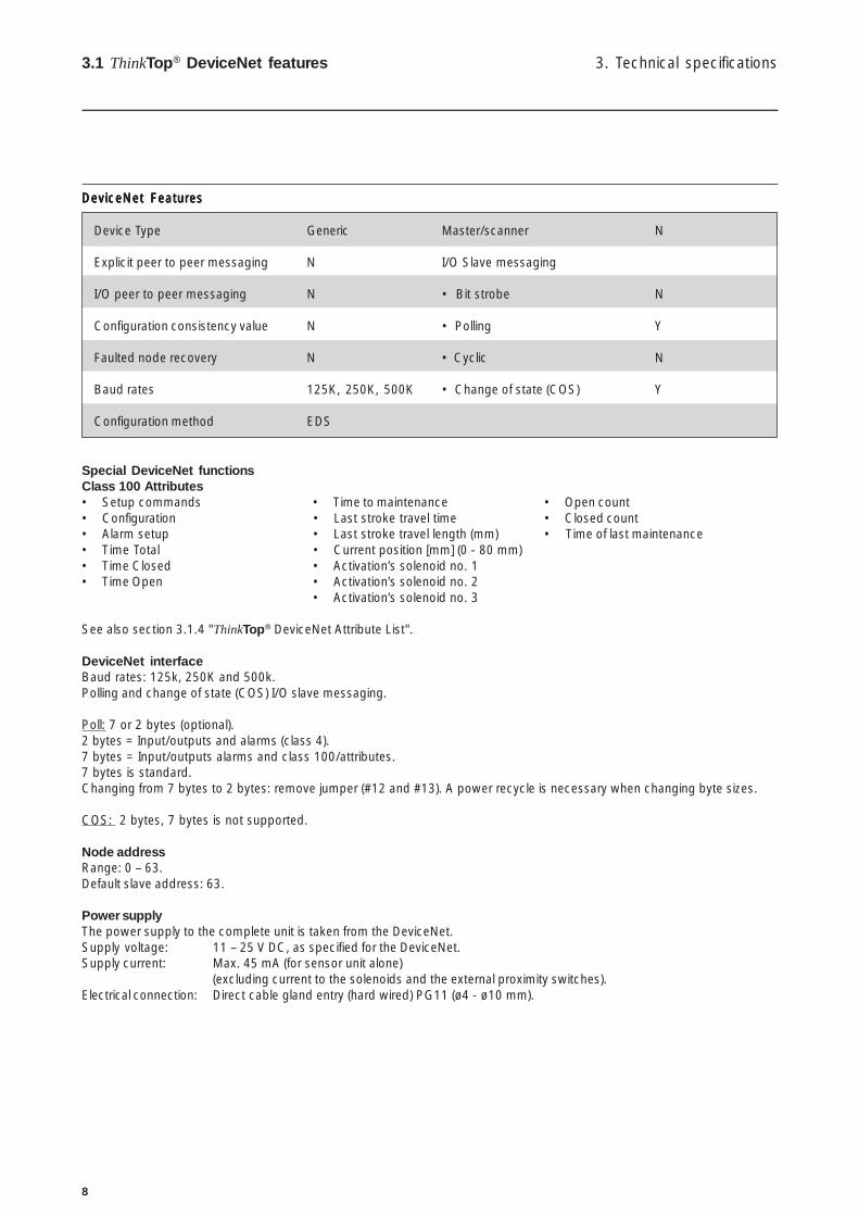
DeviceNet FeaturesDeviceNet FeaturesDeviceNet FeaturesDeviceNet FeaturesDeviceNet Features
Device Type Generic Master/scanner N
Explicit peer to peer messaging N I/O Slave messaging
I/O peer to peer messaging N • Bit strobe N
Configuration consistency value N • Polling Y
Faulted node recovery N • Cyclic N
Baud rates 125K, 250K, 500K • Change of state (COS) Y
Configuration method EDS
Special DeviceNet functionsClass 100 Attributes• Setup commands • Time to maintenance • Open count• Configuration • Last stroke travel time • Closed count• Alarm setup • Last stroke travel length (mm) • Time of last maintenance• Time Total • Current position [mm] (0 - 80 mm)• Time Closed • Activation’s solenoid no. 1• Time Open • Activation’s solenoid no. 2
• Activation’s solenoid no. 3
See also section 3.1.4 "ThinkTop® DeviceNet Attribute List".
DeviceNet interfaceBaud rates: 125k, 250K and 500k.Polling and change of state (COS) I/O slave messaging.
Poll: 7 or 2 bytes (optional).2 bytes = Input/outputs and alarms (class 4).7 bytes = Input/outputs alarms and class 100/attributes.7 bytes is standard.Changing from 7 bytes to 2 bytes: remove jumper (#12 and #13). A power recycle is necessary when changing byte sizes.
COS: 2 bytes, 7 bytes is not supported.
Node addressRange: 0 – 63.Default slave address: 63.
Power supplyThe power supply to the complete unit is taken from the DeviceNet.Supply voltage: 11 – 25 V DC, as specified for the DeviceNet.Supply current: Max. 45 mA (for sensor unit alone)
(excluding current to the solenoids and the external proximity switches).Electrical connection: Direct cable gland entry (hard wired) PG11 (ø4 - ø10 mm).

9
3. Technical specifications 3.1 ThinkTop® DeviceNet features
3.1.1 "No Touch" sensor system
Type: Alfa Laval “No Touch” Sensor System
For wire connections: See section 4.4 "Electrical connection, internal".
FeaturesTolerance programmes.Self adjustment programme (SRC/ARC valves only).Built-in maintenance monitor.Setup by internal pushbuttons or remote control (IR Keypad).Setup and local fault supervision.Setup saved at power shutdown.Visual LED Indicator lights.
Sensor SystemUnique “No Touch” sensor system without any mechanical sensor adjustments. A magnet is mounted on the valve stem and themagnetic field (axial) is detected by sensor chips inside the sensor unit. The measuring angle from each chip is used to locate thecurrent position of the valve stem with an accuracy of ± 0.1mm. Note that the distance to the magnet can be 5 mm ± 3 mm.
Feedback signalsInput signals (produced by the sensor unit) transmitted over the DeviceNet - class 4.Five feedback signals: Closed valve, open valve, seatlift 1, seatlift 2 and status.The status signal is used for five purposes:• To indicate that a setup is in progress (LED D).• To indicate an error condition (LED D), (flashing = software error), (steady = hardware error).• To indicate that maintenance is required (LED F).• To indicate if there is a conflict in the self adjustment programme (LED F).• To indicate if no communication exists between ThinkTop® and PLC (LED D, steady).
Tolerance programme:Individual according to valve types.• Type 1: SRC/ARC and Series 700 valves.• Type 2: LKB (LKLA-T).• Type 3: Unique, SMP-SC Spillage-Free, SRC-PV and AMP.• Type 4: SMP-SC, SMP-TO, SMP-BC, SMP-BCA and SBV.• Type 0: (Preset) All Parameters Set To Default (also valid for MH Koltek valve and SMP-EC
(*) seat-lift indication not possible for SMP-EC)).Preset and reset values: Tolerance programme No. 0 (± 5mm) and all functions are disabled.NOTE! Important to select the right tolerance programme.
Sensor unit
Sensor board PLC Interface boardIRRx
LED
s
IR Remote control
TerminalsField-bus, supply voltage (DC)
(DeviceNet: 4 wires)
Term
inal
s
Internal connections
Solenoid signals (DC)
Solenoid common
External Seat-lift (DC, PNP)
Supply sensors (DC)
External connections

10
Self Adjustment (SRC/ARC valves only)The self adjustment feature is an exceptional aspect of the ThinkTop® design. A programme can be activated to allow anadjustment of the tolerance band if the seals in the valve are being compressed or are worn. When the tolerance band of the unithas been adjusted 0.3 mm, an alert warning will appear in the form of a status signal and a flashing maintenance LED. After 0.5 mmadjustment an alarm warning appears: Loss of feedback signal, status signal and steady maintenance light indicating a minimumof seal left requiring a replacement of the seal.
Built-in Maintenance MonitorThe unit can be preset to indicate when the time for maintenance of the valve has been reached. A status signal and flashingmaintenance LED can be programmed to return after 3, 6, 9 or 12 months or more.
Sensor systemSensor accuracy: ± 0,1 mm.Distance to magnet: 5 ± 3 mm.Stroke length: 0.1 - 80 mm.
TerminalsThe terminal row of the sensor unit is equipped with screw terminals for both internal as well as external cables and wires.The terminals are suitable for wires up to 0.75 mm2 (AWG 19).
External sensorsThe external sensors are used for seatlift supervision when seatlift cannot be internally detected. The sensors get their supplyvoltage from the sensor unit. They connect directly to the terminal strip on the sensor unit. If the actual setup is for internal seatlift,the corresponding external signal is not used. Otherwise the external signal logically controls the corresponding feedback to thebus interface unit.Supply voltage: Must match the network power.Supply current: Max. 15 mA per sensor.Type of sensor: 3-wire PNP-type.Cable length: Max. 3 m.
Alarm maskOutput signals received from the DeviceNet (consumed by the sensor unit).Four-bit mask to disable the alarm functions for the states “closed”, “open”, “seatlift 1” and “seatlift 2” respectively.
See also section 3.1.4 "ThinkTop® DeviceNet Attribute List".
ThinkTop® Visual Indications LED Indications
Feedback signals:Signal: "Closed valve".Signal: "Open valve".Signal: "Seatlift 1".Signal: "Seatlift 2".Signal: "Status".
For wire connections: see section 4.4 "Electrical connection, internal".
Note: If the programmer wishes to detect a physically closed valve position in an "open valve" sensor position, then there is nolonger any consistence between the sensor valve detection position and the visual indications of the ThinkTop®.
3. Technical specifications3.1 ThinkTop® DeviceNet features
LED B "Open valve" (Yellow)
IR-Receiver
LED D "Setup/Internal fault" (Red)
LED C "Seat-lift 1/2" (Yellow)
LED E "Solenoid valves" (Green)
LED F "Maintenance" (Orange)
LED A "Closed valve" (Yellow)
11
3. Technical specifications 3.1 ThinkTop® DeviceNet features
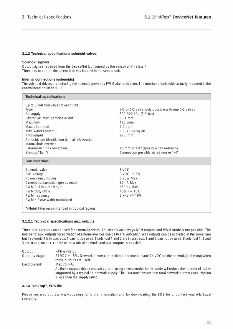
3.1.2 Technical specifications solenoid valves
Solenoid signalsOutput signals received from the DeviceNet (consumed by the sensor unit) - class 4.Three bits to control the solenoid drives located in the sensor unit.
Internal connections (solenoids)The solenoid drivers are reducing the solenoid power by PWM after activation. The number of solenoids actually mounted in thecontrol head could be 0 - 3.
Technical specifications
Up to 3 solenoid valves in each unit.Type 3/2 or 5/2 valve (only possible with one 5/2 valve).Air supply 300-900 kPa (3-9 bar).Filtered air, max. particles or dirt 0.01 mm.Max. flow 180 l/min.Max. oil content 1.0 ppm.Max. water content 0.0075 kg/kg air.Throughput ø2.5 mm.Air restriction (throttle function) air inlet/outlet.Manual hold override.External air tube connection ø6 mm or 1/4" (specify when ordering).Silencer/filter *) Connection possible via ø6 mm or 1/4".
Solenoid drive
Solenoid valve 8 VDCO/P Voltage 9 VDC +/- 5%Power consumption 0.75W Max.Current consumption (per solenoid) 30mA Max.PWM Pull-in pulse length 150ms Max.PWM duty cycle 40% +/- 10%PWM frequency 2 kHz +/- 10%PWM = Pulse width modulated
*) Note! Filter recommended in tropical regions.
3.1.2.1 Technical specifications aux. outputs
Three aux. outputs can be used for external devices. The drivers are always NPN outputs and PWM mode is not possible. Thenumber of aux. outputs for activation of external devices can be 0-3. Clarification: All 3 outputs can be activated at the same timebut if solenoid 1 is in use, aux. 1 can not be used! If solenoid 1 and 2 are in use, aux. 1 and 2 can not be used! If solenoid 1, 2 and3 are in use, no aux. can be used! A mix of solenoid and aux. outputs is possible.
Output: NPN (sinking).Output voltage: 24 VDC ± 15%. Network power connection! User must ensure 24 VDC on the network (at the top) when
these outputs are used.Load current: Max 75 mA.
As these outputs drive constant current, using several nodes in this mode will reduce the number of nodessupported by a typical 8A network supply. The user must ensure that total network current consumptionis less than the supply rating.
3.1.3 ThinkTop®, EDS file
Please see web address www.odva.org for further information and for downloading the EDS file or contact your Alfa Lavalcompany.
12
3. Technical specifications3.1 ThinkTo
p® D
eviceNet features
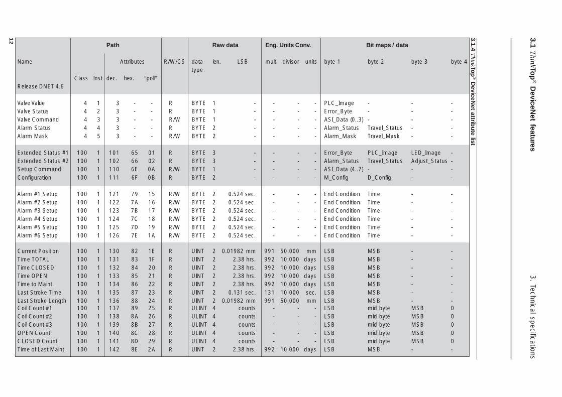
3.1.4 ThinkTop
® DeviceN
et attribute list
Path Raw data Eng. Units Conv. Bit maps / data
Name Attributes R/W/CS data len. LSB mult. divisor units byte 1 byte 2 byte 3 byte 4type
Class Inst dec. hex. “poll”Release DNET 4.6
Valve Value 4 1 3 - - R BYTE 1 - - - - PLC_Image - - -Valve Status 4 2 3 - - R BYTE 1 - - - - Error_Byte - - -Valve Command 4 3 3 - - R/W BYTE 1 - - - - ASI_Data (0..3) - - -Alarm Status 4 4 3 - - R BYTE 2 - - - - Alarm_Status Travel_Status - -Alarm Mask 4 5 3 - - R/W BYTE 2 - - - - Alarm_Mask Travel_Mask - -
Extended Status #1 100 1 101 65 01 R BYTE 3 - - - - Error_Byte PLC_Image LED_Image -Extended Status #2 100 1 102 66 02 R BYTE 3 - - - - Alarm_Status Travel_Status Adjust_Status -Setup Command 100 1 110 6E 0A R/W BYTE 1 - - - - ASI_Data (4..7) - - -Configuration 100 1 111 6F 0B R BYTE 2 - - - - M_Config D_Config - -
Alarm #1 Setup 100 1 121 79 15 R/W BYTE 2 0.524 sec. - - - End Condition Time - -Alarm #2 Setup 100 1 122 7A 16 R/W BYTE 2 0.524 sec. - - - End Condition Time - -Alarm #3 Setup 100 1 123 7B 17 R/W BYTE 2 0.524 sec. - - - End Condition Time - -Alarm #4 Setup 100 1 124 7C 18 R/W BYTE 2 0.524 sec. - - - End Condition Time - -Alarm #5 Setup 100 1 125 7D 19 R/W BYTE 2 0.524 sec. - - - End Condition Time - -Alarm #6 Setup 100 1 126 7E 1A R/W BYTE 2 0.524 sec. - - - End Condition Time - -
Current Position 100 1 130 82 1E R UINT 2 0.01982 mm 991 50,000 mm LSB MSB - -Time TOTAL 100 1 131 83 1F R UINT 2 2.38 hrs. 992 10,000 days LSB MSB - -Time CLOSED 100 1 132 84 20 R UINT 2 2.38 hrs. 992 10,000 days LSB MSB - -Time OPEN 100 1 133 85 21 R UINT 2 2.38 hrs. 992 10,000 days LSB MSB - -Time to Maint. 100 1 134 86 22 R UINT 2 2.38 hrs. 992 10,000 days LSB MSB - -Last Stroke Time 100 1 135 87 23 R UINT 2 0.131 sec. 131 10,000 sec. LSB MSB - -Last Stroke Length 100 1 136 88 24 R UINT 2 0.01982 mm 991 50,000 mm LSB MSB - -Coil Count #1 100 1 137 89 25 R ULINT 4 counts - - - LSB mid byte MSB 0Coil Count #2 100 1 138 8A 26 R ULINT 4 counts - - - LSB mid byte MSB 0Coil Count #3 100 1 139 8B 27 R ULINT 4 counts - - - LSB mid byte MSB 0OPEN Count 100 1 140 8C 28 R ULINT 4 counts - - - LSB mid byte MSB 0CLOSED Count 100 1 141 8D 29 R ULINT 4 counts - - - LSB mid byte MSB 0Time of Last Maint. 100 1 142 8E 2A R UINT 2 2.38 hrs. 992 10,000 days LSB MSB - -
13
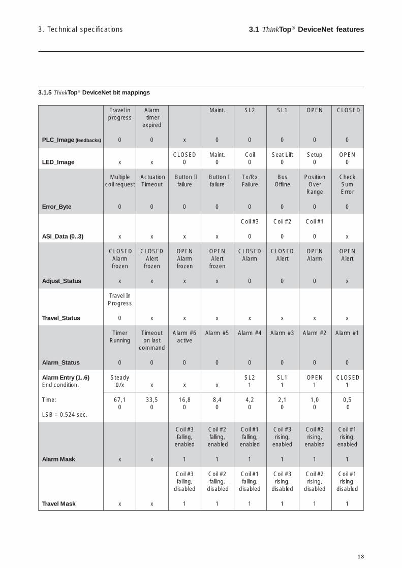
Travel in Alarm Maint. SL2 SL1 OPEN CLOSEDprogress timer
expired
PLC_Image (feedbacks) 0 0 x 0 0 0 0 0
CLOSED Maint. Coil Seat Lift Setup OPENLED_Image x x 0 0 0 0 0 0
Multiple Actuation Button II Button I Tx/Rx Bus Position Checkcoil request Timeout failure failure Failure Offline Over Sum
Range Error
Error_Byte 0 0 0 0 0 0 0 0
Coil #3 Coil #2 Coil #1
ASI_Data (0..3) x x x x 0 0 0 x
CLOSED CLOSED OPEN OPEN CLOSED CLOSED OPEN OPENAlarm Alert Alarm Alert Alarm Alert Alarm Alertfrozen frozen frozen frozen
Adjust_Status x x x x 0 0 0 x
Travel InProgress
Travel_Status 0 x x x x x x x
Timer Timeout Alarm #6 Alarm #5 Alarm #4 Alarm #3 Alarm #2 Alarm #1Running on last active
command
Alarm_Status 0 0 0 0 0 0 0 0
Alarm Entry (1..6) Steady SL2 SL1 OPEN CLOSEDEnd condition: 0/x x x x 1 1 1 1
Time: 67,1 33,5 16,8 8,4 4,2 2,1 1,0 0,50 0 0 0 0 0 0 0
LSB = 0.524 sec.
Coil #3 Coil #2 Coil #1 Coil #3 Coil #2 Coil #1falling, falling, falling, rising, rising, rising,
enabled enabled enabled enabled enabled enabled
Alarm Mask x x 1 1 1 1 1 1
Coil #3 Coil #2 Coil #1 Coil #3 Coil #2 Coil #1falling, falling, falling, rising, rising, rising,
disabled disabled disabled disabled disabled disabled
Travel Mask x x 1 1 1 1 1 1
3. Technical specifications 3.1 ThinkTop® DeviceNet features
3.1.5 ThinkTop® DeviceNet bit mappings
14
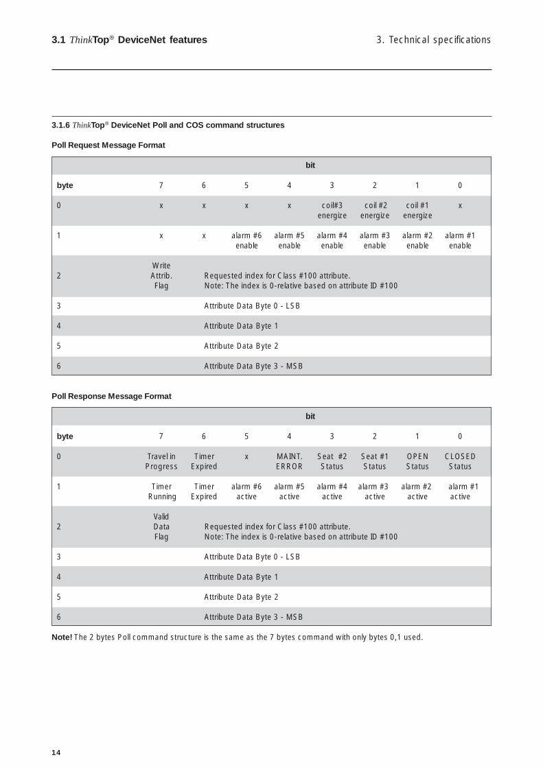
3. Technical specifications3.1 ThinkTop® DeviceNet features
3.1.6 ThinkTop® DeviceNet Poll and COS command structures
Poll Request Message Format
bit
byte 7 6 5 4 3 2 1 0
0 x x x x coil#3 coil #2 coil #1 xenergize energize energize
1 x x alarm #6 alarm #5 alarm #4 alarm #3 alarm #2 alarm #1enable enable enable enable enable enable
Write2 Attrib. Requested index for Class #100 attribute.
Flag Note: The index is 0-relative based on attribute ID #100
3 Attribute Data Byte 0 - LSB
4 Attribute Data Byte 1
5 Attribute Data Byte 2
6 Attribute Data Byte 3 - MSB
Poll Response Message Format
bit
byte 7 6 5 4 3 2 1 0
0 Travel in Timer x MAINT. Seat #2 Seat #1 OPEN CLOSEDProgress Expired ERROR Status Status Status Status
1 Timer Timer alarm #6 alarm #5 alarm #4 alarm #3 alarm #2 alarm #1 Running Expired active active active active active active
Valid2 Data Requested index for Class #100 attribute.
Flag Note: The index is 0-relative based on attribute ID #100
3 Attribute Data Byte 0 - LSB
4 Attribute Data Byte 1
5 Attribute Data Byte 2
6 Attribute Data Byte 3 - MSB
Note! The 2 bytes Poll command structure is the same as the 7 bytes command with only bytes 0,1 used.

15
COS command structure
COS Request MessageBy definition the COS and Poll Request Messages are identical. For a device configured for a 7 bytes Poll, the corresponding COSrequest will be:
bit
byte 7 6 5 4 3 2 1 0
0 x x x x coil#3 coil #2 coil #1 xenergize energize energize
1 x x alarm #6 alarm #5 alarm #4 alarm #3 alarm #2 alarm #1enable enable enable enable enable enable
Write2 Attrib. Requested index for Class #100 attribute.
Flag Note: The index is 0-relative based on attribute ID #100
3 Attribute Data Byte 0 - LSB
4 Attribute Data Byte 1
5 Attribute Data Byte 2
6 Attribute Data Byte 3 - MSB
For a device configured for a 2 bytes Poll, the corresponding COS request will be
bit
byte 7 6 5 4 3 2 1 0
0 x x x x Coil #3 Coil #2 Coil #1 xenergize energize energize
1 x x alarm #6 alarm #5 alarm #4 alarm #3 alarm #2 alarm #1enable enable enable enable enable enable
COS Response Message:Only a 2 bytes message is supported and corresponds to the 2 bytes Poll response message format
bit
byte 7 6 5 4 3 2 1 0
0 Travel Timer x MAINT. Seat #2 Seat #1 OPEN CLOSEDin Expired ERROR Status Status Status status
Progress
1 Timer Timer alarm #6 alarm #5 alarm #4 alarm #3 alarm #2 alarm #1Running Expired active active active active active active
Note! A 7 bytes COS response message is not supported.
COS Trigger:The COS message is triggered by any change in the Valve Value (feedbacks) corresponding to byte-0 of the COS responsemessage.
3. Technical specifications 3.1 ThinkTop® DeviceNet features
16
3. Technical specifications3.1 ThinkTop® DeviceNet features
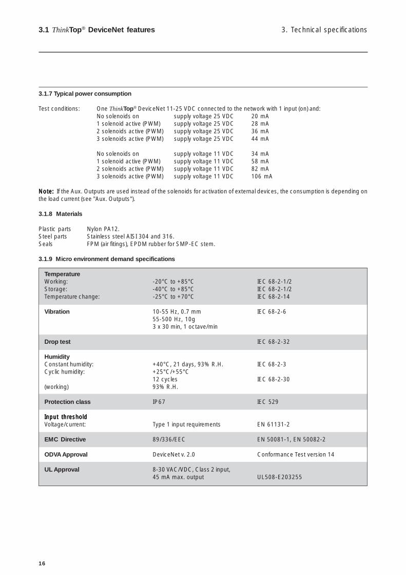
3.1.7 Typical power consumption
Test conditions: One ThinkTop® DeviceNet 11-25 VDC connected to the network with 1 input (on) and:No solenoids on supply voltage 25 VDC 20 mA1 solenoid active (PWM) supply voltage 25 VDC 28 mA2 solenoids active (PWM) supply voltage 25 VDC 36 mA3 solenoids active (PWM) supply voltage 25 VDC 44 mA
No solenoids on supply voltage 11 VDC 34 mA1 solenoid active (PWM) supply voltage 11 VDC 58 mA2 solenoids active (PWM) supply voltage 11 VDC 82 mA3 solenoids active (PWM) supply voltage 11 VDC 106 mA
Note:Note:Note:Note:Note: If the Aux. Outputs are used instead of the solenoids for activation of external devices, the consumption is depending onthe load current (see "Aux. Outputs").
3.1.8 Materials
Plastic parts Nylon PA12.Steel parts Stainless steel AISI 304 and 316.Seals FPM (air fitings), EPDM rubber for SMP-EC stem.
3.1.9 Micro environment demand specifications
TemperatureWorking: -20°C to +85°C IEC 68-2-1/2Storage: -40°C to +85°C IEC 68-2-1/2Temperature change: -25°C to +70°C IEC 68-2-14
Vibration 10-55 Hz, 0.7 mm IEC 68-2-655-500 Hz, 10g3 x 30 min, 1 octave/min
Drop test IEC 68-2-32
HumidityConstant humidity: +40°C, 21 days, 93% R.H. IEC 68-2-3Cyclic humidity: +25°C/+55°C
12 cycles IEC 68-2-30(working) 93% R.H.
Protection class IP67 IEC 529
Input thresholdInput thresholdInput thresholdInput thresholdInput thresholdVoltage/current: Type 1 input requirements EN 61131-2
EMC Directive 89/336/EEC EN 50081-1, EN 50082-2
ODVA Approval DeviceNet v. 2.0 Conformance Test version 14
UL Approval 8-30 VAC/VDC, Class 2 input,45 mA max. output UL508-E203255
17
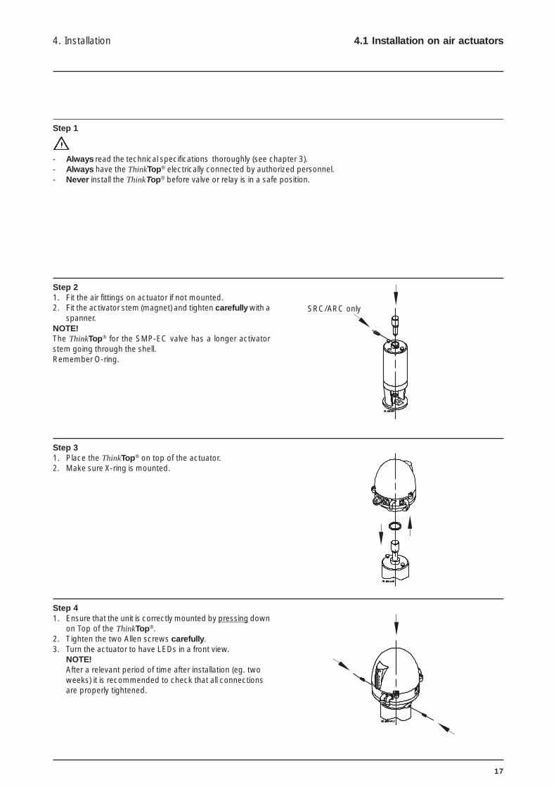
Step 1
- Always read the technical specifications thoroughly (see chapter 3).- Always have the ThinkTop® electrically connected by authorized personnel.- Never install the ThinkTop® before valve or relay is in a safe position.
Step 21. Fit the air fittings on actuator if not mounted.2. Fit the activator stem (magnet) and tighten carefully with a
spanner.NOTE!The ThinkTop® for the SMP-EC valve has a longer activatorstem going through the shell.Remember O-ring.
Step 31. Place the ThinkTop® on top of the actuator.2. Make sure X-ring is mounted.
Step 41. Ensure that the unit is correctly mounted by pressing down
on Top of the ThinkTop®.2. Tighten the two Allen screws carefully.3. Turn the actuator to have LEDs in a front view.
NOTE!After a relevant period of time after installation (eg. twoweeks) it is recommended to check that all connectionsare properly tightened.
4. Installation 4.1 Installation on air actuators
SRC/ARC only

18
4. Installation4.1 Installation on air actuators
Step 5Fit the ø6 mm (1/4") air tubes to ThinkTop® (see drawing "Airconnections" later in this chapter).
Step 6Fit the air tubes to the actuator (see drawing "Air connections"later in this chapter).
Step 7Untighten the three screws and pull off cover of ThinkTop®.
Step 81. Install cable (if not present) through the cable gland.2. Connect the ThinkTop® electrically (see section 4.4
"Electrical connection, internal").
19
4. Installation 4.1 Installation on air actuators
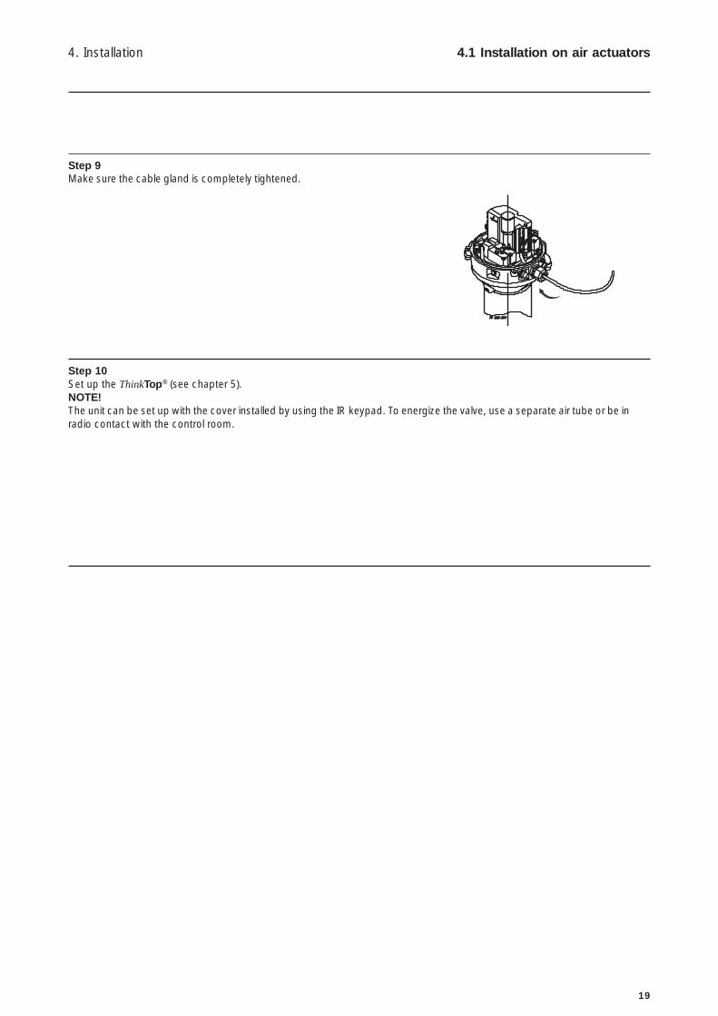
Step 9Make sure the cable gland is completely tightened.
Step 10Set up the ThinkTop® (see chapter 5).NOTE!The unit can be set up with the cover installed by using the IR keypad. To energize the valve, use a separate air tube or be inradio contact with the control room.
20
4. Installation4.2 Installation on Series 700 valves
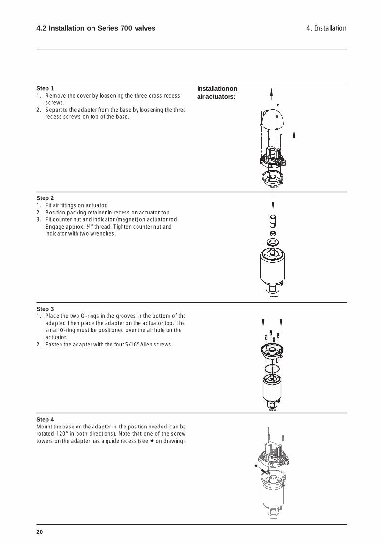
Installation onair actuators:
Step 11. Remove the cover by loosening the three cross recess
screws.2. Separate the adapter from the base by loosening the three
recess screws on top of the base.
Step 21. Fit air fittings on actuator.2. Position packing retainer in recess on actuator top.3. Fit counter nut and indicator (magnet) on actuator rod.
Engage approx. ¼” thread. Tighten counter nut andindicator with two wrenches.
Step 31. Place the two O-rings in the grooves in the bottom of the
adapter. Then place the adapter on the actuator top. Thesmall O-ring must be positioned over the air hole on theactuator.
2. Fasten the adapter with the four 5/16” Allen screws.
Step 4Mount the base on the adapter in the position needed (can berotated 120° in both directions). Note that one of the screwtowers on the adapter has a guide recess (see ! on drawing).
!

21
4. Installation 4.3 Air connections
Air restriction (throttle function)air inlet/outlet
Air out 1A
Air exhaust
Air out 1B (5/2 portsolenoid valve only)
Solenoid valve
Air in
Air out 3
Air out 2
Manual hold override
1
2
3

22
4. Installation4.4 Electrical connection, internal
Internal connectionsto solenoid 1-3
Incoming signals fromexternal sensors
Jumper **)
Supply to externalsensors
Aux. Common(+)
Aux. 1 (-)
Aux. 2 (-)
Aux. 3 (-)
N/C
N/C
N/C
Solenoid common brown
Solenoid 1, blue
Solenoid 2, blue
Solenoid 3, blue
Power Bus V- (black)
CAN_L (blue)
Drain (bare)
CAN_H (white)
Power Bus V+ (red)
Jumper
Jumper
Seat lift 1 *) "upper"
Seat lift 2 *) "lower"
Supply + *)
Supply - *)
***)
Bus connection
*) Note!- Terminals 24, 25, 26 and 27 can be used for external seatlift sensors as well as for any digital input. They are associated with
feedback signal 3 (seatlift 1) and 4 (seatlift 2). External sensor must always be a 8-30 VDC PNP 3 wire sensor. Connect(-) common on terminal 27, and (+) common on terminal 26.
**) Note!Jumper present = 7 I/O bytes; Rx size 7 and Tx size 7 - standard.Changing from 7 bytes to 2 bytes: Remove jumper ( #12 and #13). A power recycle is necessary when changing byte sizes.
***) Note!Three aux. outputs can be used for external devices. The drivers are always NPN outputs and PWM mode is not possible. Thenumber of aux. outputs for activation of external devices can be 0-3. Clarification: All 3 outputs can be activated at the sametime but if solenoid 1 is in use, aux. 1 can not be used! If solenoid 1 and 2 are in use, aux. 1 and 2 can not be used!If solenoid 1, 2 and 3 are in use, no aux. can be used! A mix of solenoid and aux. outputs is possible.Output: NPN (sinking).Output voltage: 24 VDC ± 15%. Network power connection! User must ensure 24 VDC on the network (at the top) when
these outputs are used.Load current: Max 75 mA.
As these outputs drive constant current, using several nodes in this mode will reduce the number of nodessupported by a typical 8A network supply. The user must ensure that total network current consumptionis less than the supply rating.

23
24
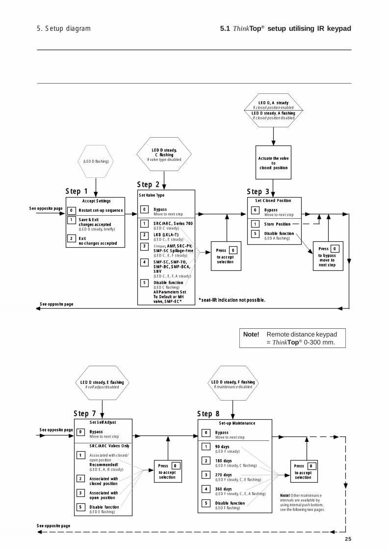
5. Setup diagram5.1 ThinkTop® setup utilising IR keypad
EnterEnterEnterEnterEnterSet-up SequenceSet-up SequenceSet-up SequenceSet-up SequenceSet-up Sequence
00000
LED D steady,then flashing
Set Open PositionSet Open PositionSet Open PositionSet Open PositionSet Open Position
00000 BypassBypassBypassBypassBypassMove to next step
11111 Store PositionStore PositionStore PositionStore PositionStore Position
55555 Disable functionDisable functionDisable functionDisable functionDisable function(LED B flashing)
Actuate theActuate theActuate theActuate theActuate thevalve tovalve tovalve tovalve tovalve to
open positionopen positionopen positionopen positionopen position
Set Upper Seat LiftSet Upper Seat LiftSet Upper Seat LiftSet Upper Seat LiftSet Upper Seat Lift
00000 BypassBypassBypassBypassBypassMove to next step
11111 Store PositionStore PositionStore PositionStore PositionStore Position
55555 Disable functionDisable functionDisable functionDisable functionDisable function(LED B flashing)
LED D, C, B steadyLED D, C, B steadyLED D, C, B steadyLED D, C, B steadyLED D, C, B steadyif upper seat lift enabled
LED D, C steadyLED D, C steadyLED D, C steadyLED D, C steadyLED D, C steady, B flashing B flashing B flashing B flashing B flashing if upper seat lift disabled
Actuate theActuate theActuate theActuate theActuate thevalve tovalve tovalve tovalve tovalve to
upper seat liftupper seat liftupper seat liftupper seat liftupper seat lift
Press 0Press 0Press 0Press 0Press 0
to bypassto bypassto bypassto bypassto bypassmove tomove tomove tomove tomove tonext stepnext stepnext stepnext stepnext step
Press 0Press 0Press 0Press 0Press 0
to bypassto bypassto bypassto bypassto bypassmove tomove tomove tomove tomove tonext stepnext stepnext stepnext stepnext step
LED D, C, A steadyLED D, C, A steadyLED D, C, A steadyLED D, C, A steadyLED D, C, A steadyif lower seat lift enabled
LED D, C steadyLED D, C steadyLED D, C steadyLED D, C steadyLED D, C steady, A flashingA flashingA flashingA flashingA flashingif lower seat lift disabled
Set Lower Seat LiftSet Lower Seat LiftSet Lower Seat LiftSet Lower Seat LiftSet Lower Seat Lift
00000 BypassBypassBypassBypassBypassMove to next step
11111 Store PositionStore PositionStore PositionStore PositionStore Position
55555 Disable functionDisable functionDisable functionDisable functionDisable function(LED A flashing)
Actuate theActuate theActuate theActuate theActuate thevalve tovalve tovalve tovalve tovalve to
lower seat liftlower seat liftlower seat liftlower seat liftlower seat lift
LED D, B steadyLED D, B steadyLED D, B steadyLED D, B steadyLED D, B steadyif open position enabled
LED D steadyLED D steadyLED D steadyLED D steadyLED D steady, B flashingB flashingB flashingB flashingB flashingif open position disabled
Step 4Step 4Step 4Step 4Step 4 Step 5Step 5Step 5Step 5Step 5 Step 6Step 6Step 6Step 6Step 6
See opposite pageSee opposite pageSee opposite pageSee opposite pageSee opposite page
See opposite pageSee opposite pageSee opposite pageSee opposite pageSee opposite page
See opposite pageSee opposite pageSee opposite pageSee opposite pageSee opposite page
See opposite pageSee opposite pageSee opposite pageSee opposite pageSee opposite page
Press 0Press 0Press 0Press 0Press 0
to bypassto bypassto bypassto bypassto bypassmove tomove tomove tomove tomove tonext stepnext stepnext stepnext stepnext step
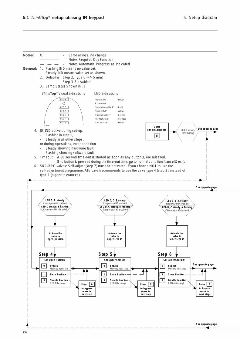
Notes: O - Scroll across, no change- Notes Requires Key Function
- - Notes Automatic Progress as IndicatedGeneral: 1. Flashing IND means no value set.
Steady IND means value set as shown.2. Default is: Step 2, Type 0 (+/- 5 mm)
Step 3-8 disabled3. Lamp Status Shown in [ ]
4. [D] IND active during set-up.- Flashing in step 1,- Steady in all other steps.or during operations, error condition- Steady showing hardware fault- Flashing showing software fault
5. Timeout: A 60 second time-out is started as soon as any button(s) are released.If no button is pressed during the time-out time, go to normal condition (cancel & exit).
6. SRC/ARC valves: Self-adjust (step 7) must be activated. If you choose NOT to use theself-adjustment programme, Alfa Laval recommends to use the valve type 4 (step 2), instead oftype 1 (bigger tolerances).
LED B "Open valve" (Yellow)
IR-Receiver
LED D "Setup/Internal fault" (Red)
LED C "Seat-lift 1/2" (Yellow)
LED E "Solenoid valves" (Green)
LED F "Maintenance" (Orange)
LED A "Closed valve" (Yellow)
ThinkTop® Visual Indications LED Indications
25
Accept SettingsAccept SettingsAccept SettingsAccept SettingsAccept Settings
00000 Restart set-up sequenceRestart set-up sequenceRestart set-up sequenceRestart set-up sequenceRestart set-up sequence
11111 Save & ExitSave & ExitSave & ExitSave & ExitSave & Exitchanges acceptedchanges acceptedchanges acceptedchanges acceptedchanges accepted(LED D steady, briefly)
22222 ExitExitExitExitExitno changes acceptedno changes acceptedno changes acceptedno changes acceptedno changes accepted
Set V Set V Set V Set V Set Valve Talve Talve Talve Talve Typeypeypeypeype
00000 BypassBypassBypassBypassBypassMove to next step
11111 SRC/ARC, Series 700SRC/ARC, Series 700SRC/ARC, Series 700SRC/ARC, Series 700SRC/ARC, Series 700(LED C steady)
22222 LKB (LKLA-T)LKB (LKLA-T)LKB (LKLA-T)LKB (LKLA-T)LKB (LKLA-T)(LED C, E steady)
33333 Unique, AMP, AMP, AMP, AMP, AMP, SRC-PV, SRC-PV, SRC-PV, SRC-PV, SRC-PV,,,,,SMP-SC Spillage-FreeSMP-SC Spillage-FreeSMP-SC Spillage-FreeSMP-SC Spillage-FreeSMP-SC Spillage-Free(LED C, E, F steady)
44444 SMP-SC, SMP-TO,SMP-SC, SMP-TO,SMP-SC, SMP-TO,SMP-SC, SMP-TO,SMP-SC, SMP-TO,SMP-BC, SMP-BCA,SMP-BC, SMP-BCA,SMP-BC, SMP-BCA,SMP-BC, SMP-BCA,SMP-BC, SMP-BCA,SBVSBVSBVSBVSBV(LED C, E, F, A steady)
55555 Disable functionDisable functionDisable functionDisable functionDisable function(LED C flashing)All Parameters SetAll Parameters SetAll Parameters SetAll Parameters SetAll Parameters SetTTTTTo Default or MHo Default or MHo Default or MHo Default or MHo Default or MHvalve, SMP-EC*valve, SMP-EC*valve, SMP-EC*valve, SMP-EC*valve, SMP-EC*
Press 0Press 0Press 0Press 0Press 0
to acceptto acceptto acceptto acceptto acceptselectionselectionselectionselectionselection
Actuate the valveActuate the valveActuate the valveActuate the valveActuate the valvet ot ot ot ot o
closed positionclosed positionclosed positionclosed positionclosed position
Set Closed PositionSet Closed PositionSet Closed PositionSet Closed PositionSet Closed Position
00000 BypassBypassBypassBypassBypassMove to next step
11111 Store PositionStore PositionStore PositionStore PositionStore Position
55555 Disable functionDisable functionDisable functionDisable functionDisable function(LED A flashing)
LED D steadyLED D steadyLED D steadyLED D steadyLED D steady,,,,,C flashingC flashingC flashingC flashingC flashing
if valve type disabled
Press 0Press 0Press 0Press 0Press 0
to bypassto bypassto bypassto bypassto bypassmove tomove tomove tomove tomove tonext stepnext stepnext stepnext stepnext step
Set-up MaintenanceSet-up MaintenanceSet-up MaintenanceSet-up MaintenanceSet-up Maintenance
00000 BypassBypassBypassBypassBypassMove to next step
11111 90 days90 days90 days90 days90 days(LED F steady)
22222 180 days180 days180 days180 days180 days(LED F steady, C flashing)
33333 270 days270 days270 days270 days270 days(LED F steady, C, E flashing)
44444 360 days360 days360 days360 days360 days(LED F steady, C, E, A flashing)
55555 Disable functionDisable functionDisable functionDisable functionDisable function(LED F flashing)
LED D steadyLED D steadyLED D steadyLED D steadyLED D steady, F flashing, F flashing, F flashing, F flashing, F flashingif maintenance disabled
(LED D flashing)
Set Self AdjustSet Self AdjustSet Self AdjustSet Self AdjustSet Self Adjust
00000 BypassBypassBypassBypassBypassMove to next step
SRC/ARC Valves OnlySRC/ARC Valves OnlySRC/ARC Valves OnlySRC/ARC Valves OnlySRC/ARC Valves Only
11111 Associated with closed/open positionRecommended!Recommended!Recommended!Recommended!Recommended!(LED E, A, B steady)
22222 Associated withAssociated withAssociated withAssociated withAssociated withclosed positionclosed positionclosed positionclosed positionclosed position
33333 Associated withAssociated withAssociated withAssociated withAssociated withopen positionopen positionopen positionopen positionopen position
55555 Disable functionDisable functionDisable functionDisable functionDisable function(LED E flashing)
LED D steadyLED D steadyLED D steadyLED D steadyLED D steady, E flashing, E flashing, E flashing, E flashing, E flashingif self adjust disabled
Press 0Press 0Press 0Press 0Press 0
to acceptto acceptto acceptto acceptto acceptselectionselectionselectionselectionselection
Step 1Step 1Step 1Step 1Step 1
* seat-lift indication not possible.* seat-lift indication not possible.* seat-lift indication not possible.* seat-lift indication not possible.* seat-lift indication not possible.
Note! Remote distance keypad= ThinkTop® 0-300 mm.
Step 2Step 2Step 2Step 2Step 2Step 3Step 3Step 3Step 3Step 3
Step 7Step 7Step 7Step 7Step 7 Step 8Step 8Step 8Step 8Step 8
See opposite page See opposite page See opposite page See opposite page See opposite page
See opposite pageSee opposite pageSee opposite pageSee opposite pageSee opposite page
See opposite pageSee opposite pageSee opposite pageSee opposite pageSee opposite page
See opposite pageSee opposite pageSee opposite pageSee opposite pageSee opposite page
Press 0Press 0Press 0Press 0Press 0
to acceptto acceptto acceptto acceptto acceptselectionselectionselectionselectionselection
Note! Note! Note! Note! Note! Other maintenanceintervals are available byusing internal push bottom,see the following two pages.
5. Setup diagram 5.1 ThinkTop® setup utilising IR keypad
LED D, A steadyLED D, A steadyLED D, A steadyLED D, A steadyLED D, A steadyif closed position enabled
LED D steadyLED D steadyLED D steadyLED D steadyLED D steady, A flashingA flashingA flashingA flashingA flashing if closed position disabled
26
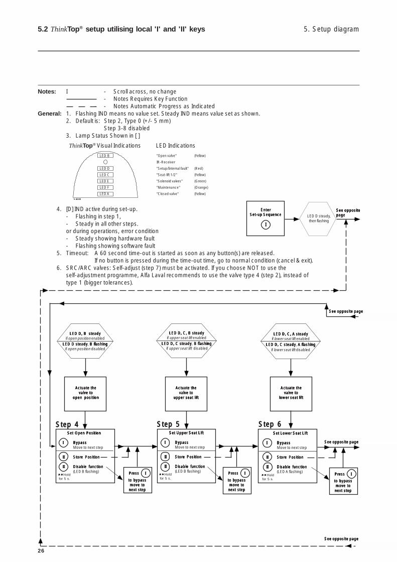
5. Setup diagram5.2 ThinkTop® setup utilising local 'I' and 'II' keys
Notes: I - Scroll across, no change- Notes Requires Key Function
- - Notes Automatic Progress as IndicatedGeneral: 1. Flashing IND means no value set. Steady IND means value set as shown.
2. Default is: Step 2, Type 0 (+/- 5 mm)Step 3-8 disabled
3. Lamp Status Shown in [ ]
4. [D] IND active during set-up.- Flashing in step 1,- Steady in all other steps.or during operations, error condition- Steady showing hardware fault- Flashing showing software fault
5. Timeout: A 60 second time-out is started as soon as any button(s) are released.If no button is pressed during the time-out time, go to normal condition (cancel & exit).
6. SRC/ARC valves: Self-adjust (step 7) must be activated. If you choose NOT to use theself-adjustment programme, Alfa Laval recommends to use the valve type 4 (step 2), instead oftype 1 (bigger tolerances).
EnterEnterEnterEnterEnterSet-up SequenceSet-up SequenceSet-up SequenceSet-up SequenceSet-up Sequence
IIIII
LED D steady,then flashing
Actuate theActuate theActuate theActuate theActuate thevalve tovalve tovalve tovalve tovalve to
open positionopen positionopen positionopen positionopen position
Actuate theActuate theActuate theActuate theActuate thevalve tovalve tovalve tovalve tovalve to
upper seat liftupper seat liftupper seat liftupper seat liftupper seat lift
Actuate theActuate theActuate theActuate theActuate thevalve tovalve tovalve tovalve tovalve to
lower seat liftlower seat liftlower seat liftlower seat liftlower seat lift
Set Open PositionSet Open PositionSet Open PositionSet Open PositionSet Open Position
IIIII BypassBypassBypassBypassBypassMove to next step
IIIIIIIIII Store PositionStore PositionStore PositionStore PositionStore Position
IIIIIIIIII Disable functionDisable functionDisable functionDisable functionDisable function(LED B flashing) Press IPress IPress IPress IPress I
to bypassto bypassto bypassto bypassto bypassmove tomove tomove tomove tomove tonext stepnext stepnext stepnext stepnext step
Set Upper Seat LiftSet Upper Seat LiftSet Upper Seat LiftSet Upper Seat LiftSet Upper Seat Lift
IIIII BypassBypassBypassBypassBypassMove to next step
IIIIIIIIII Store PositionStore PositionStore PositionStore PositionStore Position
IIIIIIIIII Disable functionDisable functionDisable functionDisable functionDisable function(LED B flashing) Press IPress IPress IPress IPress I
to bypassto bypassto bypassto bypassto bypassmove tomove tomove tomove tomove tonext stepnext stepnext stepnext stepnext step
Set Lower Seat LiftSet Lower Seat LiftSet Lower Seat LiftSet Lower Seat LiftSet Lower Seat Lift
IIIII BypassBypassBypassBypassBypassMove to next step
IIIIIIIIII Store PositionStore PositionStore PositionStore PositionStore Position
IIIIIIIIII Disable functionDisable functionDisable functionDisable functionDisable function(LED A flashing)
Press IPress IPress IPress IPress I
to bypassto bypassto bypassto bypassto bypassmove tomove tomove tomove tomove tonext stepnext stepnext stepnext stepnext step
LED D, B steadyLED D, B steadyLED D, B steadyLED D, B steadyLED D, B steadyif open position enabled
LED D steadyLED D steadyLED D steadyLED D steadyLED D steady, B flashingB flashingB flashingB flashingB flashingif open position disabled
""""""""""Holdfor 5 s.
""""""""""Holdfor 5 s.
LED D, C, B steadyLED D, C, B steadyLED D, C, B steadyLED D, C, B steadyLED D, C, B steadyif upper seat lift enabled
LED D, C steadyLED D, C steadyLED D, C steadyLED D, C steadyLED D, C steady, B flashing B flashing B flashing B flashing B flashing if upper seat lift disabled
LED D, C, A steadyLED D, C, A steadyLED D, C, A steadyLED D, C, A steadyLED D, C, A steadyif lower seat lift enabled
LED D, C steadyLED D, C steadyLED D, C steadyLED D, C steadyLED D, C steady, A flashingA flashingA flashingA flashingA flashingif lower seat lift disabled
""""""""""Holdfor 5 s.
Step 4Step 4Step 4Step 4Step 4 Step 5Step 5Step 5Step 5Step 5 Step 6Step 6Step 6Step 6Step 6
See oppositeSee oppositeSee oppositeSee oppositeSee oppositepagepagepagepagepage
See opposite pageSee opposite pageSee opposite pageSee opposite pageSee opposite page
See opposite pageSee opposite pageSee opposite pageSee opposite pageSee opposite page
See opposite pageSee opposite pageSee opposite pageSee opposite pageSee opposite page
ThinkTop® Visual Indications LED Indications
LED B "Open valve" (Yellow)
IR-Receiver
LED D "Setup/Internal fault" (Red)
LED C "Seat-lift 1/2" (Yellow)
LED E "Solenoid valves" (Green)
LED F "Maintenance" (Orange)
LED A "Closed valve" (Yellow)
27
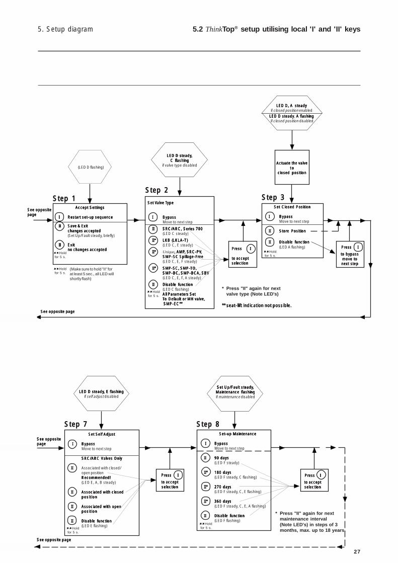
5. Setup diagram 5.2 ThinkTop® setup utilising local 'I' and 'II' keys
Press IPress IPress IPress IPress I
to acceptto acceptto acceptto acceptto acceptselectionselectionselectionselectionselection
Actuate the valveActuate the valveActuate the valveActuate the valveActuate the valvet ot ot ot ot o
closed positionclosed positionclosed positionclosed positionclosed position
Accept SettingsAccept SettingsAccept SettingsAccept SettingsAccept Settings
IIIII Restart set-up sequenceRestart set-up sequenceRestart set-up sequenceRestart set-up sequenceRestart set-up sequence
IIIIIIIIII Save & ExitSave & ExitSave & ExitSave & ExitSave & Exitchanges acceptedchanges acceptedchanges acceptedchanges acceptedchanges accepted(Set Up/Fault steady, briefly)
IIIIIIIIII ExitExitExitExitExitno changes acceptedno changes acceptedno changes acceptedno changes acceptedno changes accepted
""""""""""Holdfor 5 s.
Set V Set V Set V Set V Set Valve Talve Talve Talve Talve Typeypeypeypeype
IIIII BypassBypassBypassBypassBypassMove to next step
IIIIIIIIII SRC/ARC, Series 700SRC/ARC, Series 700SRC/ARC, Series 700SRC/ARC, Series 700SRC/ARC, Series 700(LED C steady)
II*II*II*II*II* LKB (LKLA-T)LKB (LKLA-T)LKB (LKLA-T)LKB (LKLA-T)LKB (LKLA-T)(LED C, E steady)
II*II*II*II*II* Unique, AMP, AMP, AMP, AMP, AMP, SRC-PV, SRC-PV, SRC-PV, SRC-PV, SRC-PV,,,,,SMP-SC Spillage-FreeSMP-SC Spillage-FreeSMP-SC Spillage-FreeSMP-SC Spillage-FreeSMP-SC Spillage-Free(LED C, E, F steady)
II*II*II*II*II* SMP-SC, SMP-TO,SMP-SC, SMP-TO,SMP-SC, SMP-TO,SMP-SC, SMP-TO,SMP-SC, SMP-TO,SMP-BC, SMP-BCA, SBVSMP-BC, SMP-BCA, SBVSMP-BC, SMP-BCA, SBVSMP-BC, SMP-BCA, SBVSMP-BC, SMP-BCA, SBV(LED C, E, F, A steady)
IIIIIIIIII Disable functionDisable functionDisable functionDisable functionDisable function(LED C flashing)All Parameters SetAll Parameters SetAll Parameters SetAll Parameters SetAll Parameters SetTTTTTo Defaulto Defaulto Defaulto Defaulto Default or MH valve,or MH valve,or MH valve,or MH valve,or MH valve, SMP-EC** SMP-EC** SMP-EC** SMP-EC** SMP-EC**
Set Closed PositionSet Closed PositionSet Closed PositionSet Closed PositionSet Closed Position
IIIII BypassBypassBypassBypassBypassMove to next step
IIIIIIIIII Store PositionStore PositionStore PositionStore PositionStore Position
IIIIIIIIII Disable functionDisable functionDisable functionDisable functionDisable function(LED A flashing) Press IPress IPress IPress IPress I
to bypassto bypassto bypassto bypassto bypassmove tomove tomove tomove tomove tonext stepnext stepnext stepnext stepnext step
Set Self AdjustSet Self AdjustSet Self AdjustSet Self AdjustSet Self Adjust
I I I I I BypassBypassBypassBypassBypassMove to next step
SRC/ARC Valves OnlySRC/ARC Valves OnlySRC/ARC Valves OnlySRC/ARC Valves OnlySRC/ARC Valves Only
IIIIIIIIII Associated with closed/open positionRecommended!Recommended!Recommended!Recommended!Recommended!(LED E, A, B steady)
IIIIIIIIII Associated with closedAssociated with closedAssociated with closedAssociated with closedAssociated with closedpositionpositionpositionpositionposition
IIIIIIIIII Associated with openAssociated with openAssociated with openAssociated with openAssociated with openpositionpositionpositionpositionposition
IIIIIIIIII Disable functionDisable functionDisable functionDisable functionDisable function(LED E flashing)
Press IPress IPress IPress IPress I
to acceptto acceptto acceptto acceptto acceptselectionselectionselectionselectionselection
Set-up MaintenanceSet-up MaintenanceSet-up MaintenanceSet-up MaintenanceSet-up Maintenance
I I I I I BypassBypassBypassBypassBypassMove to next step
IIIIIIIIII 90 days90 days90 days90 days90 days(LED F steady)
II*II*II*II*II* 180 days180 days180 days180 days180 days(LED F steady, C flashing)
II*II*II*II*II* 270 days270 days270 days270 days270 days(LED F steady, C, E flashing)
II*II*II*II*II* 360 days360 days360 days360 days360 days(LED F steady, C, E, A flashing)
IIIIIIIIII Disable functionDisable functionDisable functionDisable functionDisable function (LED F flashing)
Set Up/Fault steadySet Up/Fault steadySet Up/Fault steadySet Up/Fault steadySet Up/Fault steady,,,,,Maintenance flashingMaintenance flashingMaintenance flashingMaintenance flashingMaintenance flashingif maintenance disabled
Press IPress IPress IPress IPress I
to acceptto acceptto acceptto acceptto acceptselectionselectionselectionselectionselection
(LED D flashing)
(Make sure to hold "II" forat least 5 sec., all LED willshortly flash)
""""""""""Holdfor 5 s.
LED D, A steadyLED D, A steadyLED D, A steadyLED D, A steadyLED D, A steadyif closed position enabled
LED D steadyLED D steadyLED D steadyLED D steadyLED D steady, A flashingA flashingA flashingA flashingA flashing if closed position disabled
""""""""""Holdfor 5 s.
""""""""""Holdfor 5 s.
LED D steadyLED D steadyLED D steadyLED D steadyLED D steady, E flashing, E flashing, E flashing, E flashing, E flashingif self adjust disabled
""""""""""Holdfor 5 s.
LED D steadyLED D steadyLED D steadyLED D steadyLED D steady,,,,,C flashingC flashingC flashingC flashingC flashing
if valve type disabled
* Press "II" again for nextvalve type (Note LED's)
** seat-lift indication not possible.** seat-lift indication not possible.** seat-lift indication not possible.** seat-lift indication not possible.** seat-lift indication not possible.
""""""""""Holdfor 5 s.
Step 1Step 1Step 1Step 1Step 1Step 2Step 2Step 2Step 2Step 2
Step 3Step 3Step 3Step 3Step 3
Step 7Step 7Step 7Step 7Step 7 Step 8Step 8Step 8Step 8Step 8
See oppositeSee oppositeSee oppositeSee oppositeSee oppositepagepagepagepagepage
See opposite pageSee opposite pageSee opposite pageSee opposite pageSee opposite page
See oppositeSee oppositeSee oppositeSee oppositeSee oppositepagepagepagepagepage
See opposite pageSee opposite pageSee opposite pageSee opposite pageSee opposite page
* Press "II" again for nextmaintenance interval(Note LED's) in steps of 3months, max. up to 18 years.

28
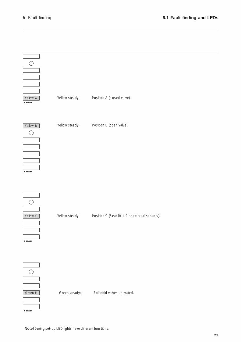
6. Fault finding6.1 Fault finding and LEDs
Below is stated the meaning of the LEDs' indications for fault finding in connection with the operation of the ThinkTop®.
Red flashing: Unit in set-up mode or internal software fault.If internal software fault, re-programme unit.
Red steady: Unit in set-up mode or internal hardware fault.If internal hardware fault, check if magnet is in range and check correct wiring.
Red steady: No communication between ThinkTop® and PLC.
1. Orange flashing: Time for maintenance has run out.The unit has been self-adjusted into a maintenance alert condition.Valve maintenance is strongly recommended. After maintenance: Disabling ofmaintenance/self-adjustment function is required before setting new position,however, it is strongly recommended to make a complete new set-up after valvemaintenance.
2. Orange steady, yellow flashing (A and/or B): The unit has been self-adjusted into a maintenance alarm condition and the feedback
is lost (a minimum of seal left).Valve maintenance is required. After maintenance: Disabling of the self-adjustmentfunction is required before setting new position, however, it is stronglyrecommended to make a complete new set up after valve maintenance.
NOTE! The maintenance indicator lighting up, and an open or closed lightflashing.....= Note the following:• Self-adjustment programme is only valid for SRC/ARC valves, do not use
the programme for other valve types.• Use tolerance/valve type 1.• In conjunction with valve type change-over; 21, 22, 31 and 32, the open
position must be defined as the upper sensor position (when the magnet isin the highest position).
• A loose top, magnet holder or sensor system can also generate the alert/alarm condition.
• Removing a ThinkTop® with self-adjust activated, will immediately generatean alarm condition! If the ThinkTop® has to be removed, not because of avalve maintenance issue, but for some other reasons, and you want to storethe already adjusted data - disable the self-adjust function before removingthe ThinkTop® and enable it again once the ThinkTop® is back on theactuator.
• After valve maintenance a disabling of the self-adjustment function isrequired before setting a new position, however, it is strongly recommendedto make a complete new set-up (disable all functions in step 2 valve type -and make a complete new set-up).
Red
Orange
Yellow A
Yellow B
29
Green steady: Solenoid valves activated.
Note! During set-up LED lights have different functions.
Yellow steady: Position C (Seat lift 1-2 or external sensors).
6. Fault finding 6.1 Fault finding and LEDs
Yellow steady: Position B (open valve).
Yellow steady: Position A (closed valve).Yellow A
Yellow B
Yellow C
Green E

30
7. Maintenance7.1 Dismantling of ThinkTop®
Step 11. Remove the ThinkTop® from the actuator.2. Pull out X-ring and replace it.
Step 21. Untighten the three screws.2. Pull off the ThinkTop® cover.
Step 31. Untighten screws.2. Remove solenoid valves (up to 3) and replace them with
new ones.
Step 41. To dismantle the adapter (the lower part of the ThinkTop®)
from base (the middle part), unscrew the three screws.2. Turn the lower part a little clockwise and pull.3. Replace adapter if necessary.
Note:Turn banjoconnection!
Study the instructions carefully.Handle scrap correctly.Always keep spare X-rings in stock.
31
7. Maintenance 7.1 Dismantling of ThinkTop®
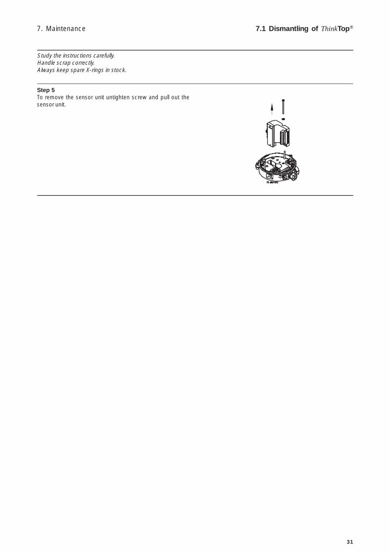
Step 5To remove the sensor unit untighten screw and pull out thesensor unit.
Study the instructions carefully.Handle scrap correctly.Always keep spare X-rings in stock.

32
7. Maintenance7.2 Assembly of ThinkTop®
Step 1Place sensor unit in base and tighten screw (torque: 1 Nm).
Step 2Assemble base with adapter by turning adapter a littleanticlockwise and tighten the three screws (1.9 Nm).
Step 31. Replace solenoid valves (up to three) with new ones.2. Tighten screws (0.2 Nm).
Step 4Replace cover of ThinkTop® and tighten the three screws(0.6 Nm).
Note:Turn banjoconnection!
Study the instructions carefully.Handle scrap correctly.Always keep spare X-rings in stock.
33
7. Maintenance 7.2 Assembly of ThinkTop®
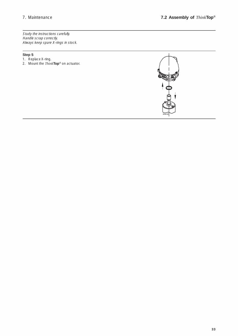
Step 51. Replace X-ring.2. Mount the ThinkTop® on actuator.
Study the instructions carefully.Handle scrap correctly.Always keep spare X-rings in stock.
34
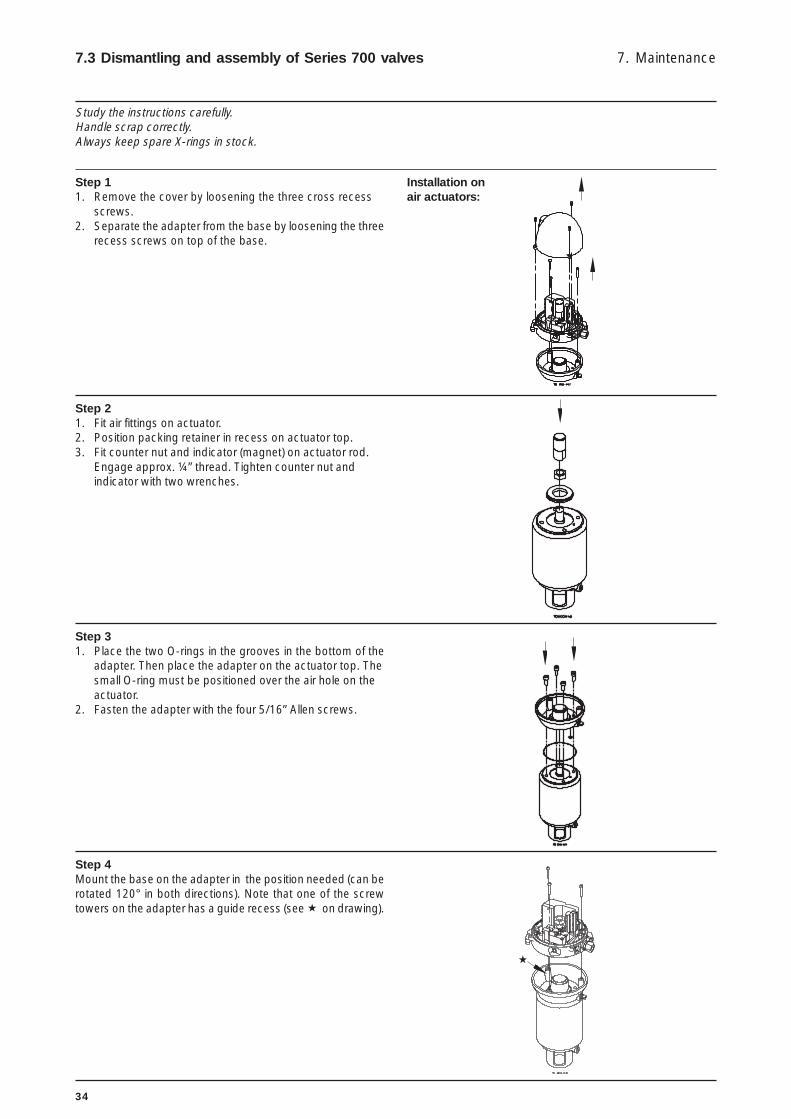
Installation onair actuators:
Step 11. Remove the cover by loosening the three cross recess
screws.2. Separate the adapter from the base by loosening the three
recess screws on top of the base.
7. Maintenance7.3 Dismantling and assembly of Series 700 valves
Step 21. Fit air fittings on actuator.2. Position packing retainer in recess on actuator top.3. Fit counter nut and indicator (magnet) on actuator rod.
Engage approx. ¼” thread. Tighten counter nut andindicator with two wrenches.
Step 31. Place the two O-rings in the grooves in the bottom of the
adapter. Then place the adapter on the actuator top. Thesmall O-ring must be positioned over the air hole on theactuator.
2. Fasten the adapter with the four 5/16” Allen screws.
Step 4Mount the base on the adapter in the position needed (can berotated 120° in both directions). Note that one of the screwtowers on the adapter has a guide recess (see ! on drawing).
!
Study the instructions carefully.Handle scrap correctly.Always keep spare X-rings in stock.

35

36
The drawing and the parts list include all items.
Parts List
Pos. Denomination
1a Shell1b Shell2 O-ring, NBR3 Screw4 Washer5 Sensor unit6 Solenoid valve7 PT screw8 Base9 O-ring, NBR10 Air fittings11 Blow-off valve12 Thread plug, PG713 Cable gland, PG11 4-10 mm14 Pressure control valve15 Adapter16 O-ring17 O-ring18 Allen screw19 Special X-ring20a Indication pin20b Indication pin21 O-ring, EPDM24 Air fitting incl. O-ring
8.1 ThinkTop® DeviceNetTM 11-25 VDC 8. Parts list
Spare Parts
Denomination Item number
Sensor unit DeviceNet 11-25 VDC ............ 9612-5627-04
Solenoid valve 3/2, 8 VDC ........................ 9611-99-3748Solenoid valve 5/2, 8 VDC ........................ 9611-99-3749
Air fitting incl. O-ring, Ø6 mm .................... 9611-99-3404Air fitting incl. O-ring, 1/4” ......................... 9611-99-3434
Note! This is the basic design.
The clearance should be approximately:
ø 225 x 250 (SRC NC, SMP-SC/-BC/-TO, Unique,Koltek MH, SBV, AMP)
ø 225 x 320 (SRC NO)ø 225 x 300 (LKB (LKLA-T))
1
2
3
171.
6
ø137
Cle
aran
ce

37
This page shows an exploded drawing of the ThinkTop®. The drawing includes all items of the top unit.
Exploded Drawing
8. Parts list 8.1 ThinkTop® DeviceNetTM 11-25 VDC

38
Spare Parts
Denomination 1/4” Air connec.
Sensor unit DeviceNet 11-25 VDC ............ 9612-5627-04
Solenoid valve 3/2, 8 VDC ........................ 9611-99-3748Solenoid valve 5/2, 8 VDC ........................ 9611-99-3749
Air fitting incl. O-ring, 1/4” ......................... 9611-99-3434
The drawing and the parts list include all items.
Parts List
Pos. Denomination
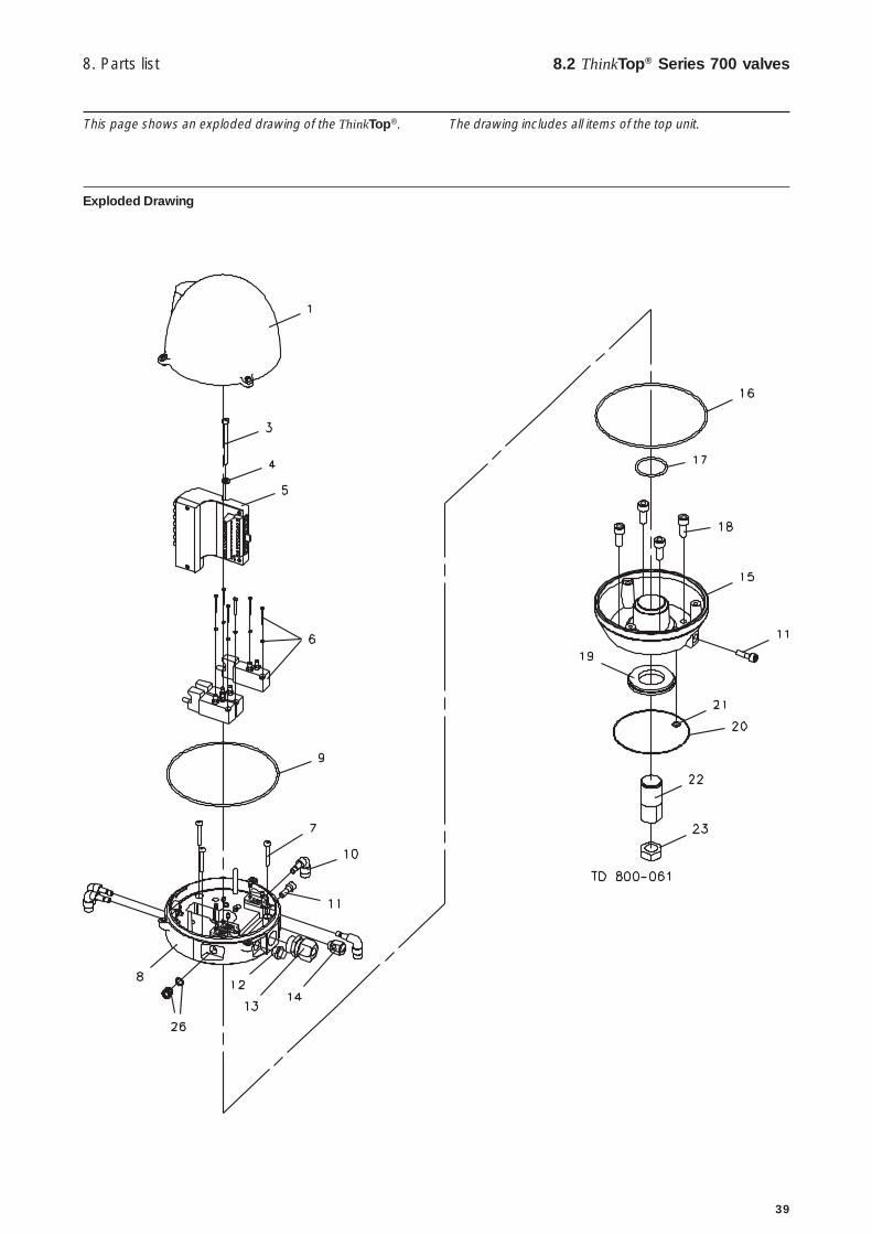
1 Shell3 Screw4 Washer5 Sensor unit6 Solenoid valve7 PT screw8 Base9 O-ring, NBR10 Air fittings11 Blow-off valve12 Thread plug, PG713 Cable gland, PG11 4-10 mm14 Pressure control valve15 Adapter16 O-ring17 O-ring18 Screw19 Retainer20 O-ring21 O-ring, EPDM22 Indicator pin23 Nut26 Air fitting incl. O-ring
8.2 ThinkTop® Series 700 valves 8. Parts list
171.
6
ø137 1
2
3
Note! This is the basic design.
The clearance should be approximately:
ø 225 x 250 (SRC NC, SMP-SC/-BC/-TO, Unique,Koltek MH, SBV, AMP)
ø 225 x 320 (SRC NO)ø 225 x 300 (LKB (LKLA-T))
Cle
aran
ce
39
This page shows an exploded drawing of the ThinkTop®. The drawing includes all items of the top unit.
Exploded Drawing
8. Parts list 8.2 ThinkTop® Series 700 valves

How to contact Alfa LavalContact details for all countries arecontinually updated on our website.Please visit www.alfalaval.com toaccess the information direct.