Embed Size (px)
Citation preview
INSTRUCTION MANUAL
AQ S215 – Bay Control IED
Instruction manual –AQ S215 Bay Control IED 2 (204)
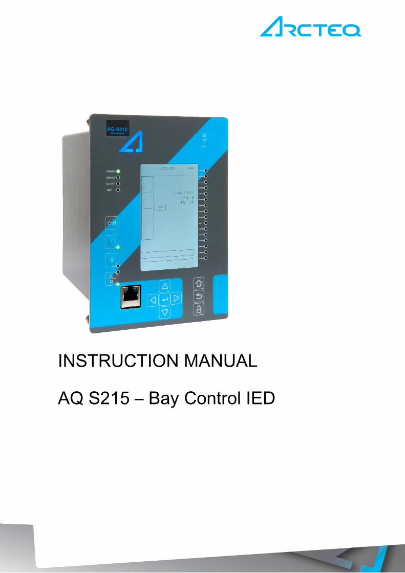
Revision 1.00
Date 8.4.2015
Changes - The first revision for AQ-S215
Revision 1.01
Date 30.5.2015
Changes - Added PCB and Terminal options to order code table.
Revision 1.02
Date 30.8.2016
Changes - Added password set up guide (previously only in AQtivate user
guide)
Revision 1.03
Date 10.2.2017
Changes - Added Programmable Control Switch, Indicator Object and
Programmable stage descriptions
- Order code update
Revision 1.04
Date 21.12.2017
Changes - Measurement value recorder description
- ZCT connection added to current measurement description
- Event lists revised on several functions
- RTD&mA card description improvements
- Auto-recloser function readability improvements
- Ring-lug CT card option description added
- Order code revised

Instruction manual –AQ S215 Bay Control IED 3 (204)
Read these instructions carefully and inspect the equipment to become familiar with it
before trying to install, operate, service or maintain it.
Electrical equipment should be installed, operated, serviced, and maintained only by
qualified personnel. Local safety regulations should be followed. No responsibility is
assumed by Arcteq for any consequences arising out of the use of this material.
We reserve right to changes without further notice.
Instruction manual –AQ S215 Bay Control IED 4 (204)
TABLE OF CONTENTS
1 ABBREVIATIONS ............................................................................................................. 6
2 GENERAL ......................................................................................................................... 7
3 IED USER INTERFACE .................................................................................................... 8
3.1 AQ 200 series local panel structure........................................................................ 8
3.2 IED programming ................................................................................................... 9
3.2.1 Basic configuration ....................................................................................... 9
3.2.2 Navigation in main configuration menus ...................................................... 10
4 FUNCTIONS OF AQ-S215 BAY CONTROL IED ............................................................. 19
4.1 Control functions .................................................................................................. 20
4.1.1 Object control and monitoring (OBJ) ........................................................... 20
4.1.2 Indicator object monitoring (CIN) ................................................................. 32
4.1.3 Programmable control switch ...................................................................... 34
4.1.4 Setting group selection (SGS) ..................................................................... 34
4.1.5 Auto-reclosing 0 1 (79) ........................................................................... 44
4.1.6 Cold load pick-up (CLPU) ........................................................................... 75
4.1.7 Switch on to fault (SOTF) ............................................................................ 85
4.1.8 Synchrocheck function ΔV/Δa/Δf (25) ......................................................... 88
4.1.9 Programmable stage PGx >/< (99) ............................................................. 98
4.2 Monitoring functions ........................................................................................... 109
4.2.1 Current transformer supervision ................................................................ 109
4.2.2 Voltage transformer supervision (60) ........................................................ 119
4.2.3 Disturbance recorder ................................................................................ 123
4.2.4 Measurement recorder .............................................................................. 137
4.2.5 Circuit breaker wear-monitor (CBW) ......................................................... 141
4.2.6 Total harmonic distortion monitor (THD) ................................................... 147
4.2.7 Fault locator (FLX) .................................................................................... 153
4.2.8 Measurement value recorder .................................................................... 156
5 SYSTEM INTEGRATION .............................................................................................. 160
5.1 Communication protocols ................................................................................... 160
5.1.1 NTP .......................................................................................................... 160
5.1.2 ModbusTCP and ModbusRTU .................................................................. 161
5.1.3 ModbusIO ................................................................................................. 162
5.1.4 IEC 61850 ................................................................................................. 163
5.1.5 GOOSE .................................................................................................... 167
5.1.6 IEC 103 ..................................................................................................... 168
5.1.7 DNP3 ........................................................................................................ 169
Instruction manual –AQ S215 Bay Control IED 5 (204)
5.1.8 IEC 101 / 104 ............................................................................................ 169
5.1.9 SPA protocol ............................................................................................. 170
5.2 General IO analog fault registers ....................................................................... 170
6 CONNECTIONS ............................................................................................................ 171
7 CONSTRUCTION AND INSTALLATION ....................................................................... 174
7.1 CPU, IO and Power supply module .................................................................... 177
7.1.1 Scanning cycle of the digital input ............................................................. 178
7.2 Digital input module DI8 ..................................................................................... 179
7.2.1 Setting up the activation and release thresholds of the digital inputs ......... 180
7.3 Digital output module DO5 ................................................................................. 181
7.4 RTD & mA input module (option) ....................................................................... 182
7.5 Serial RS232 & Serial fiber module (option) ....................................................... 184
7.6 Double LC 100 Mb Ethernet module (option) ..................................................... 185
7.7 Installation and dimensions ................................................................................ 186
8 TECHNICAL DATA ....................................................................................................... 188
8.1 Connections ....................................................................................................... 188
8.1.1 Measurements .......................................................................................... 188
8.1.2 Auxiliary voltage ........................................................................................ 191
8.1.3 Binary inputs ............................................................................................. 191
8.1.4 Binary outputs ........................................................................................... 192
8.2 Control functions ................................................................................................ 193
8.3 Monitoring functions ........................................................................................... 197
8.4 Tests and environmental .................................................................................... 201
8.4.1 Electrical environment compatibility .......................................................... 201
8.4.2 Physical environment compatibility ........................................................... 202
8.4.3 Casing and package ................................................................................. 202
9 ORDERING INFORMATION ......................................................................................... 203
10 REFERENCE INFORMATION ...................................................................................... 204

Instruction manual –AQ S215 Bay Control IED 6 (204)
1 ABBREVIATIONS
CB – Circuit breaker
CBFP – Circuit breaker failure protection
CT – Current transformer
CPU – Central processing unit
EMC – Electromagnetic compatibility
HMI – Human machine interface
HW – Hardware
IED – Intelligent electronic device
IO – Input output
LED – Light emitting diode
LV – Low voltage
MV – Medium voltage
NC – Normally closed
NO – Normally open
RMS – Root mean square
SF – System failure
TMS – Time multiplier setting
TRMS – True root mean square
VAC – Voltage alternating current
VDC – Voltage direct current
SW – Software
uP - Microprocessor

Instruction manual –AQ S215 Bay Control IED 7 (204)
2 GENERAL
The AQ-S215 Bay Control IED is a member of the AQ-200 product line. The AQ-200
protection product line in respect of hardware and software is a modular device. The
hardware modules are assembled and configured according to the application IO
requirements and the software determines the available functions. This manual describes
the specific application of the AQ-S215 Bay Control IED.
AQ S215 bay control IED may be applied for various types of control applications. The AQ
S215 comes with full current, voltage, power and energy measurement capability and may
be equipped with additional I/O depending on application needs. Easy to use and powerful
logic programming expands further the application range to more demanding control, alarm
and indication needs.
AQ-S215 can be programmed using easy to use AQtivate 200 setting and configuration
software.
Instruction manual –AQ S215 Bay Control IED 8 (204)
3 IED USER INTERFACE
AQ 200 series IED user interface section is divided into hardware- and software user
interface sections. Software interface is divided into local panel configuration and
programming by using AQtivate 200 freeware software suite.
3.1 AQ 200 SERIES LOCAL PANEL STRUCTURE
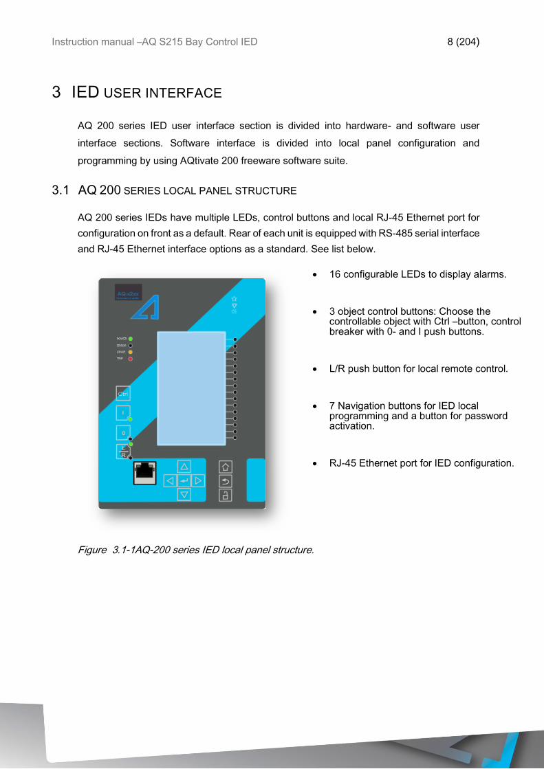
AQ 200 series IEDs have multiple LEDs, control buttons and local RJ-45 Ethernet port for
configuration on front as a default. Rear of each unit is equipped with RS-485 serial interface
and RJ-45 Ethernet interface options as a standard. See list below.
• 16 configurable LEDs to display alarms.
• 3 object control buttons: Choose the controllable object with Ctrl –button, control breaker with 0- and I push buttons.
• L/R push button for local remote control.
• 7 Navigation buttons for IED local programming and a button for password activation.
• RJ-45 Ethernet port for IED configuration.
Figure 3.1-1AQ-200 series IED local panel structure.
Instruction manual –AQ S215 Bay Control IED 9 (204)
3.2 IED PROGRAMMING
3.2.1 BASIC CONFIGURATION
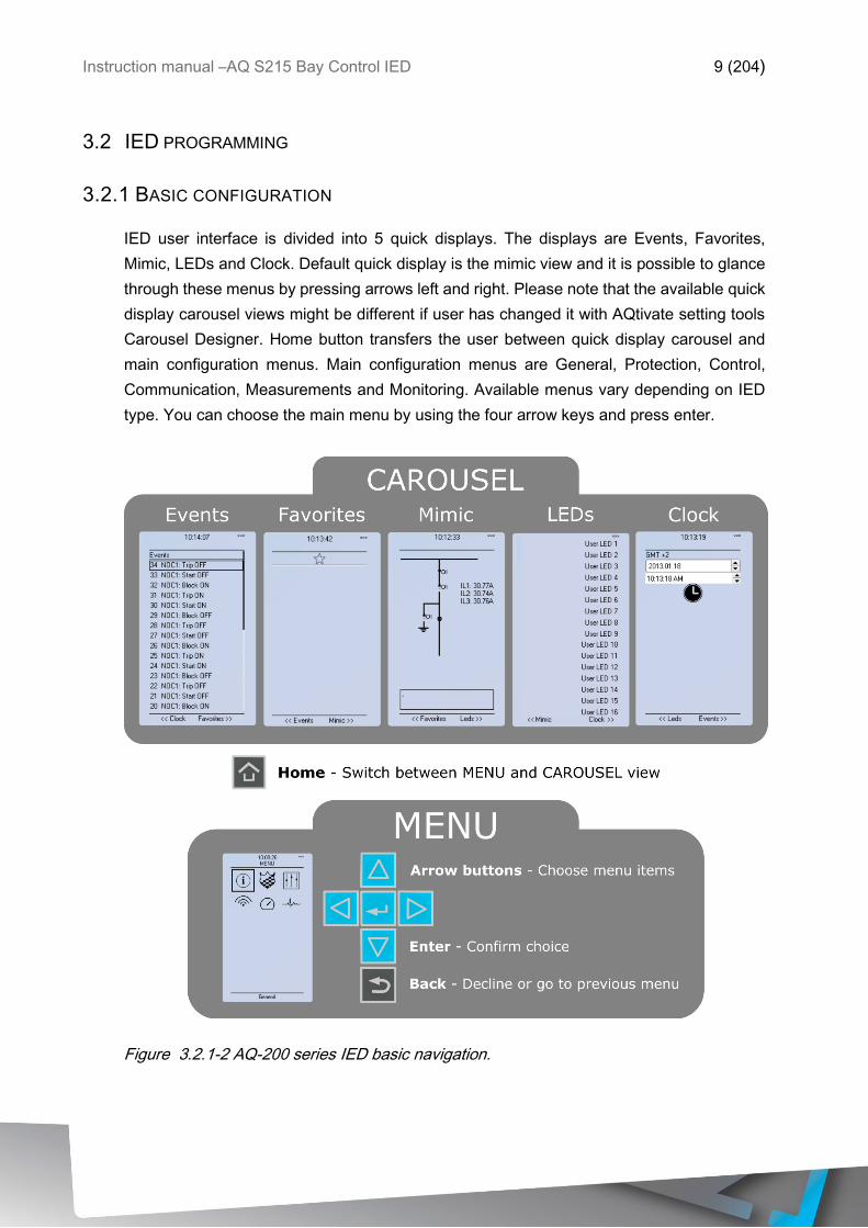
IED user interface is divided into 5 quick displays. The displays are Events, Favorites,
Mimic, LEDs and Clock. Default quick display is the mimic view and it is possible to glance
through these menus by pressing arrows left and right. Please note that the available quick
display carousel views might be different if user has changed it with AQtivate setting tools
Carousel Designer. Home button transfers the user between quick display carousel and
main configuration menus. Main configuration menus are General, Protection, Control,
Communication, Measurements and Monitoring. Available menus vary depending on IED
type. You can choose the main menu by using the four arrow keys and press enter.
Figure 3.2.1-2 AQ-200 series IED basic navigation.
Instruction manual –AQ S215 Bay Control IED 10 (204)
Cancel key takes you one step back or holding it down for 3 seconds takes
you back to general –menu .Cancel key is also used for alarm LEDs reset.
• Padlock button takes user to password menu where it is possible to enter
different user levels (user, operator, configurator and super user).
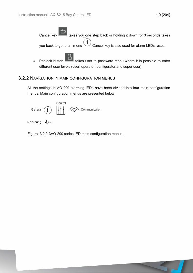
3.2.2 NAVIGATION IN MAIN CONFIGURATION MENUS
All the settings in AQ-200 alarming IEDs have been divided into four main configuration
menus. Main configuration menus are presented below.
Figure 3.2.2-3AQ-200 series IED main configuration menus.
Instruction manual –AQ S215 Bay Control IED 11 (204)
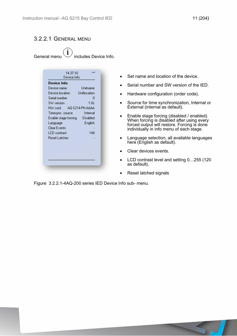
3.2.2.1 GENERAL MENU
General menu includes Device Info.
• Set name and location of the device. • Serial number and SW version of the IED.
• Hardware configuration (order code).
• Source for time synchronization, Internal or
External (internal as default).
• Enable stage forcing (disabled / enabled). When forcing is disabled after using every forced output will restore. Forcing is done individually in info menu of each stage.
• Language selection, all available languages
here (English as default).
• Clear devices events.
• LCD contrast level and setting 0…255 (120 as default).
• Reset latched signals
Figure 3.2.2.1-4AQ-200 series IED Device Info sub- menu.
Instruction manual –AQ S215 Bay Control IED 12 (204)
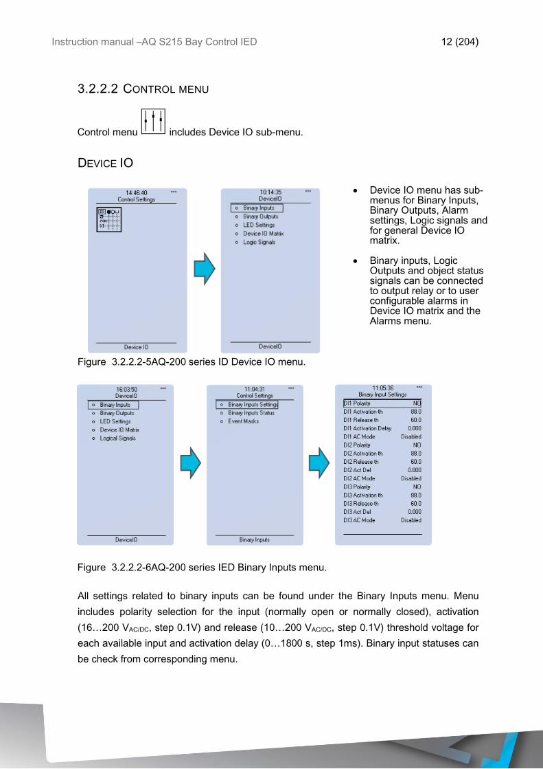
3.2.2.2 CONTROL MENU
Control menu includes Device IO sub-menu.
DEVICE IO
• Device IO menu has sub-menus for Binary Inputs, Binary Outputs, Alarm settings, Logic signals and for general Device IO matrix.
• Binary inputs, Logic
Outputs and object status signals can be connected to output relay or to user configurable alarms in Device IO matrix and the Alarms menu.
Figure 3.2.2.2-5AQ-200 series ID Device IO menu.
Figure 3.2.2.2-6AQ-200 series IED Binary Inputs menu.
All settings related to binary inputs can be found under the Binary Inputs menu. Menu
includes polarity selection for the input (normally open or normally closed), activation
(16…200 VAC/DC, step 0.1V) and release (10…200 VAC/DC, step 0.1V) threshold voltage for
each available input and activation delay (0…1800 s, step 1ms). Binary input statuses can
be check from corresponding menu.
Instruction manual –AQ S215 Bay Control IED 13 (204)
Events are masked off as default. It is possible to activate desired events by masking them
|x|. Only masked events appear to event list which can be viewed in the carousel view (if
Events-display has been activated). Events can be cleared in General menu.
Digital input activation and release threshold follows the measured peak value. Activation
time of input is between 5-10 milliseconds. Activation delay is configurable. Release time
with DC is between 5-10 milliseconds. Release time with AC is less than 25 milliseconds.
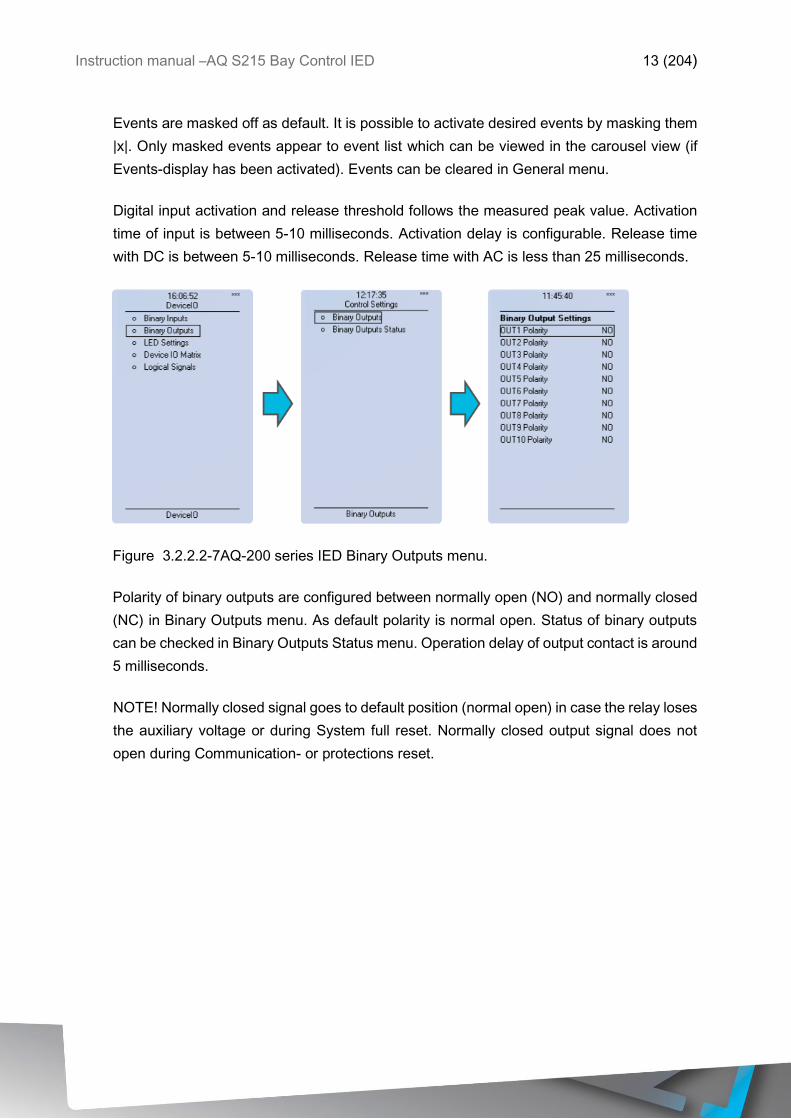
Figure 3.2.2.2-7AQ-200 series IED Binary Outputs menu.
Polarity of binary outputs are configured between normally open (NO) and normally closed
(NC) in Binary Outputs menu. As default polarity is normal open. Status of binary outputs
can be checked in Binary Outputs Status menu. Operation delay of output contact is around
5 milliseconds.
NOTE! Normally closed signal goes to default position (normal open) in case the relay loses
the auxiliary voltage or during System full reset. Normally closed output signal does not
open during Communication- or protections reset.
Instruction manual –AQ S215 Bay Control IED 14 (204)
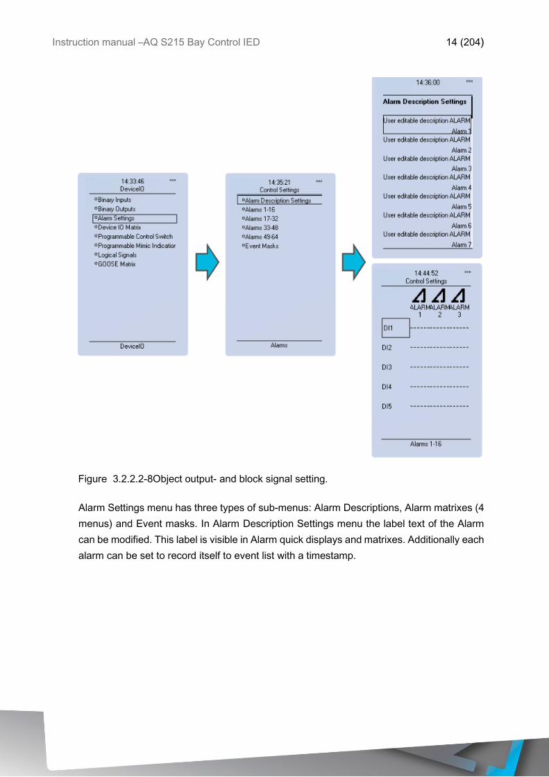
Figure 3.2.2.2-8Object output- and block signal setting.
Alarm Settings menu has three types of sub-menus: Alarm Descriptions, Alarm matrixes (4
menus) and Event masks. In Alarm Description Settings menu the label text of the Alarm
can be modified. This label is visible in Alarm quick displays and matrixes. Additionally each
alarm can be set to record itself to event list with a timestamp.
Instruction manual –AQ S215 Bay Control IED 15 (204)
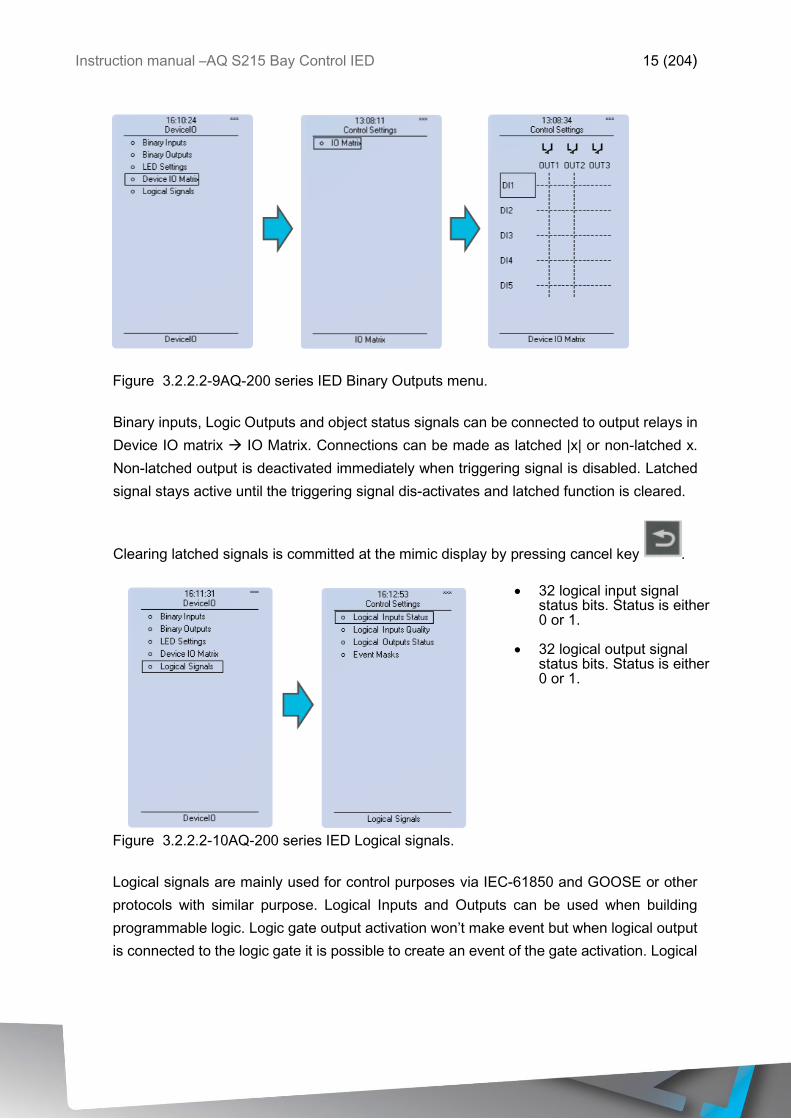
Figure 3.2.2.2-9AQ-200 series IED Binary Outputs menu.
Binary inputs, Logic Outputs and object status signals can be connected to output relays in
Device IO matrix IO Matrix. Connections can be made as latched |x| or non-latched x.
Non-latched output is deactivated immediately when triggering signal is disabled. Latched
signal stays active until the triggering signal dis-activates and latched function is cleared.
Clearing latched signals is committed at the mimic display by pressing cancel key .
• 32 logical input signal status bits. Status is either 0 or 1.
• 32 logical output signal
status bits. Status is either 0 or 1.
Figure 3.2.2.2-10AQ-200 series IED Logical signals.
Logical signals are mainly used for control purposes via IEC-61850 and GOOSE or other
protocols with similar purpose. Logical Inputs and Outputs can be used when building
programmable logic. Logic gate output activation won’t make event but when logical output
is connected to the logic gate it is possible to create an event of the gate activation. Logical
Instruction manual –AQ S215 Bay Control IED 16 (204)
inputs and outputs have on and off events those can be masked on (off as default). For
more detailed description of the logic editor please refer to AQtivate Instruction Booklet.
Note! System integration chapter gives more details of use of the logical signals generally.
3.2.2.3 COMMUNICATION MENU
Communication menu includes Connections and Protocols sub-menus. AQ-200
series IEDs can be configured through rear Ethernet by using AQtivate 200 setting and
configuration software suite.IP address of the IED can be checked from the Connections
menu.
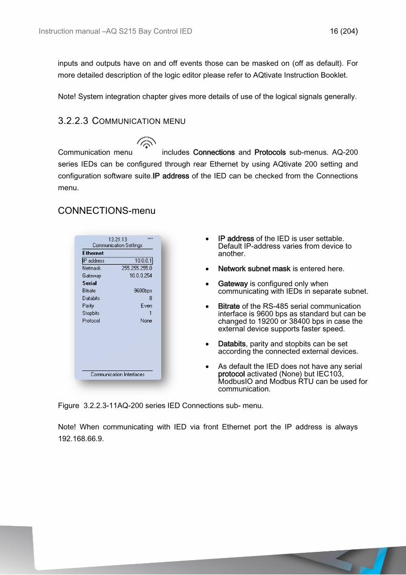
CONNECTIONS-menu
• IP address of the IED is user settable.
Default IP-address varies from device to another.
• Network subnet mask is entered here.
• Gateway is configured only when
communicating with IEDs in separate subnet.
• Bitrate of the RS-485 serial communication interface is 9600 bps as standard but can be changed to 19200 or 38400 bps in case the external device supports faster speed.
• Databits, parity and stopbits can be set
according the connected external devices.
• As default the IED does not have any serial protocol activated (None) but IEC103, ModbusIO and Modbus RTU can be used for communication.
Figure 3.2.2.3-11AQ-200 series IED Connections sub- menu.
Note! When communicating with IED via front Ethernet port the IP address is always
192.168.66.9.
Instruction manual –AQ S215 Bay Control IED 17 (204)
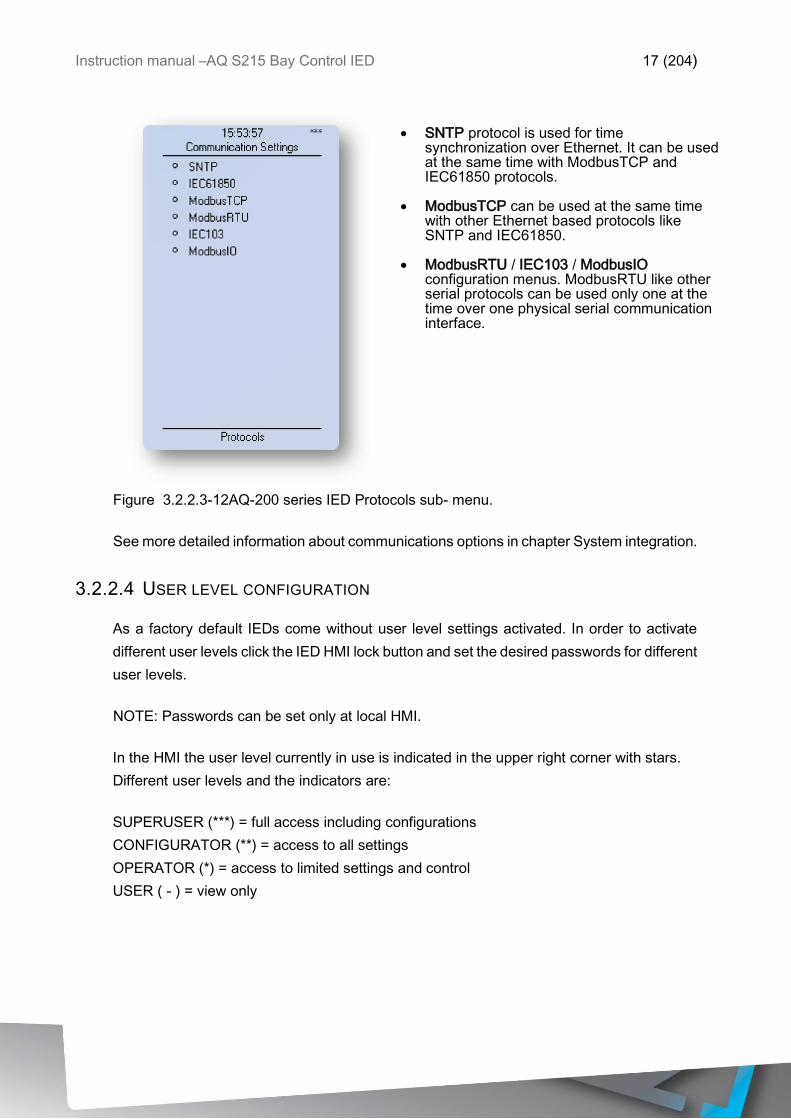
• SNTP protocol is used for time
synchronization over Ethernet. It can be used at the same time with ModbusTCP and IEC61850 protocols.
• ModbusTCP can be used at the same time
with other Ethernet based protocols like SNTP and IEC61850.
• ModbusRTU / IEC103 / ModbusIO
configuration menus. ModbusRTU like other serial protocols can be used only one at the time over one physical serial communication interface.
Figure 3.2.2.3-12AQ-200 series IED Protocols sub- menu.
See more detailed information about communications options in chapter System integration.
3.2.2.4 USER LEVEL CONFIGURATION
As a factory default IEDs come without user level settings activated. In order to activate
different user levels click the IED HMI lock button and set the desired passwords for different
user levels.
NOTE: Passwords can be set only at local HMI.
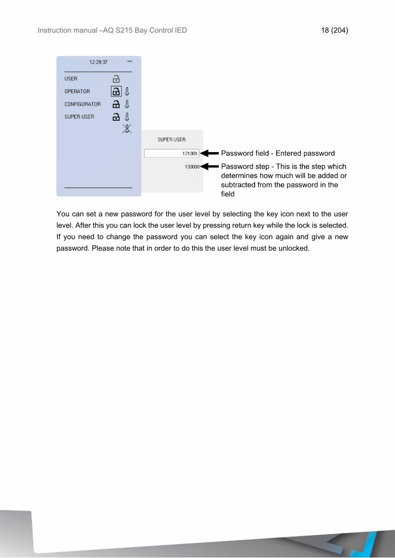
In the HMI the user level currently in use is indicated in the upper right corner with stars.
Different user levels and the indicators are:
SUPERUSER (***) = full access including configurations
CONFIGURATOR (**) = access to all settings
OPERATOR (*) = access to limited settings and control
USER ( - ) = view only
Instruction manual –AQ S215 Bay Control IED 18 (204)
You can set a new password for the user level by selecting the key icon next to the user
level. After this you can lock the user level by pressing return key while the lock is selected.
If you need to change the password you can select the key icon again and give a new
password. Please note that in order to do this the user level must be unlocked.
Instruction manual –AQ S215 Bay Control IED 19 (204)
4 FUNCTIONS OF AQ-S215 BAY CONTROL IED
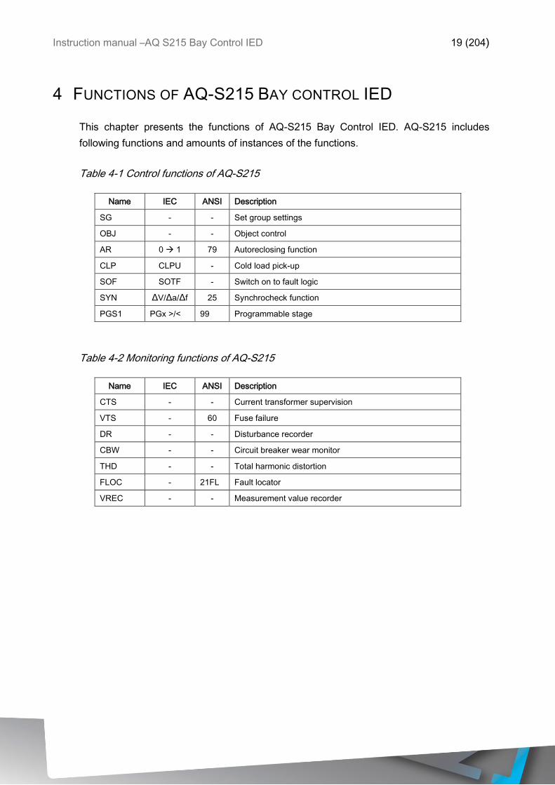
This chapter presents the functions of AQ-S215 Bay Control IED. AQ-S215 includes
following functions and amounts of instances of the functions.
Table 4-1 Control functions of AQ-S215
Name IEC ANSI Description
SG - - Set group settings
OBJ - - Object control
AR 0 1 79 Autoreclosing function
CLP CLPU - Cold load pick-up
SOF SOTF - Switch on to fault logic
SYN ΔV/Δa/Δf 25 Synchrocheck function
PGS1 PGx >/< 99 Programmable stage
Table 4-2 Monitoring functions of AQ-S215
Name IEC ANSI Description
CTS - - Current transformer supervision
VTS - 60 Fuse failure
DR - - Disturbance recorder
CBW - - Circuit breaker wear monitor
THD - - Total harmonic distortion
FLOC - 21FL Fault locator
VREC - - Measurement value recorder

Instruction manual –AQ S215 Bay Control IED 20 (204)
4.1 CONTROL FUNCTIONS
4.1.1 OBJECT CONTROL AND MONITORING (OBJ)
Object control and monitoring function takes care of circuit breaker and disconnector
controlling and status monitoring. Monitor and control is based into the statuses of the IED
binary inputs and outputs configured. In the relay the amount of controllable and monitored
objects is dependent of available IO. One controllable object requires minimum of 2 output
contacts. For status monitoring typically 2 binary inputs are utilized per monitored object.
Alternatively object status monitoring can be performed with single digital input using rising
and falling edge monitoring and logic virtual inputs.
Object can be controlled from local control, remote control and HMI mimic manually or by
software function automatically. For remote control from protocols the modes “Direct
Control” and “Select before Execute” are dealt in the protocol handling itself.
Object control consists of control logic, control monitor and output handler. In addition of
these main parts in the object control block can be added object related CBFP and object
wear monitor. For the basic version of the object control block these additional functions are
not included.
Outputs of the function are Object open and Object close control signals. In addition to these
output controls the function will report the monitored object status and applied operations.
Setting parameters are static inputs for the function which are changed only by user input
in the setup phase of the function.
Inputs for the function are binary status indications open and close control signals,
blockings, object ready and synchrocheck monitor signals. The function registers its
operation into 12 last time-stamped registers and also generates general time stamped
ON/OFF events to the common event buffer from each of the two output signal as well as
several operational event signals. Time stamp resolution is 1ms. Function provides also
cumulative counters for Open and Close act and Open / Close Failed events.
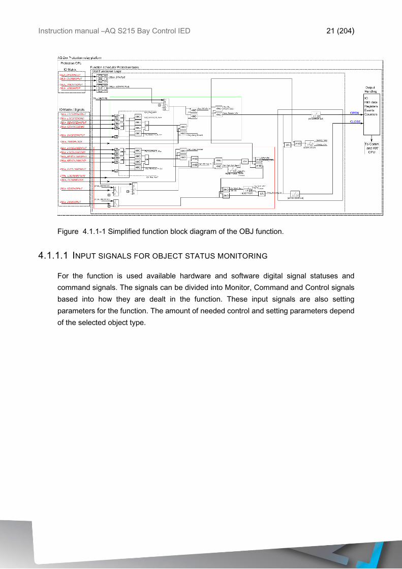
In the following figure is presented the simplified function block diagram of the OBJ function.
Instruction manual –AQ S215 Bay Control IED 21 (204)
Figure 4.1.1-1 Simplified function block diagram of the OBJ function.
4.1.1.1 INPUT SIGNALS FOR OBJECT STATUS MONITORING
For the function is used available hardware and software digital signal statuses and
command signals. The signals can be divided into Monitor, Command and Control signals
based into how they are dealt in the function. These input signals are also setting
parameters for the function. The amount of needed control and setting parameters depend
of the selected object type.
Instruction manual –AQ S215 Bay Control IED 22 (204)
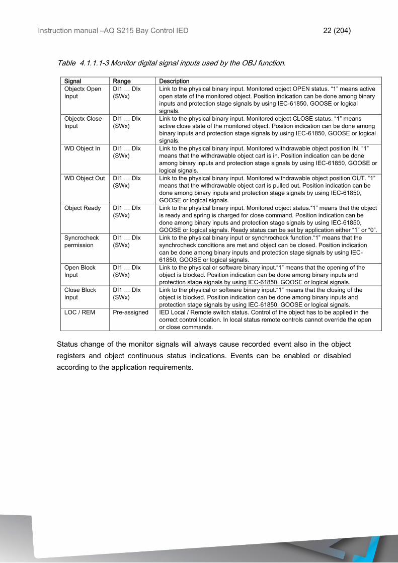
Table 4.1.1.1-3 Monitor digital signal inputs used by the OBJ function.
Signal Range Description
Objectx Open
Input
DI1 … DIx
(SWx)
Link to the physical binary input. Monitored object OPEN status. “1” means active
open state of the monitored object. Position indication can be done among binary
inputs and protection stage signals by using IEC-61850, GOOSE or logical
signals.
Objectx Close
Input
DI1 … DIx
(SWx)
Link to the physical binary input. Monitored object CLOSE status. “1” means
active close state of the monitored object. Position indication can be done among
binary inputs and protection stage signals by using IEC-61850, GOOSE or logical
signals.
WD Object In DI1 … DIx
(SWx)
Link to the physical binary input. Monitored withdrawable object position IN. “1”
means that the withdrawable object cart is in. Position indication can be done
among binary inputs and protection stage signals by using IEC-61850, GOOSE or
logical signals.
WD Object Out DI1 … DIx
(SWx)
Link to the physical binary input. Monitored withdrawable object position OUT. “1”
means that the withdrawable object cart is pulled out. Position indication can be
done among binary inputs and protection stage signals by using IEC-61850,
GOOSE or logical signals.
Object Ready DI1 … DIx
(SWx)
Link to the physical binary input. Monitored object status.“1” means that the object
is ready and spring is charged for close command. Position indication can be
done among binary inputs and protection stage signals by using IEC-61850,
GOOSE or logical signals. Ready status can be set by application either “1” or “0”.
Syncrocheck
permission
DI1 … DIx
(SWx)
Link to the physical binary input or synchrocheck function.“1” means that the
synchrocheck conditions are met and object can be closed. Position indication
can be done among binary inputs and protection stage signals by using IEC-
61850, GOOSE or logical signals.
Open Block
Input
DI1 … DIx
(SWx)
Link to the physical or software binary input.“1” means that the opening of the
object is blocked. Position indication can be done among binary inputs and
protection stage signals by using IEC-61850, GOOSE or logical signals.
Close Block
Input
DI1 … DIx
(SWx)
Link to the physical or software binary input.“1” means that the closing of the
object is blocked. Position indication can be done among binary inputs and
protection stage signals by using IEC-61850, GOOSE or logical signals.
LOC / REM Pre-assigned IED Local / Remote switch status. Control of the object has to be applied in the
correct control location. In local status remote controls cannot override the open
or close commands.
Status change of the monitor signals will always cause recorded event also in the object
registers and object continuous status indications. Events can be enabled or disabled
according to the application requirements.
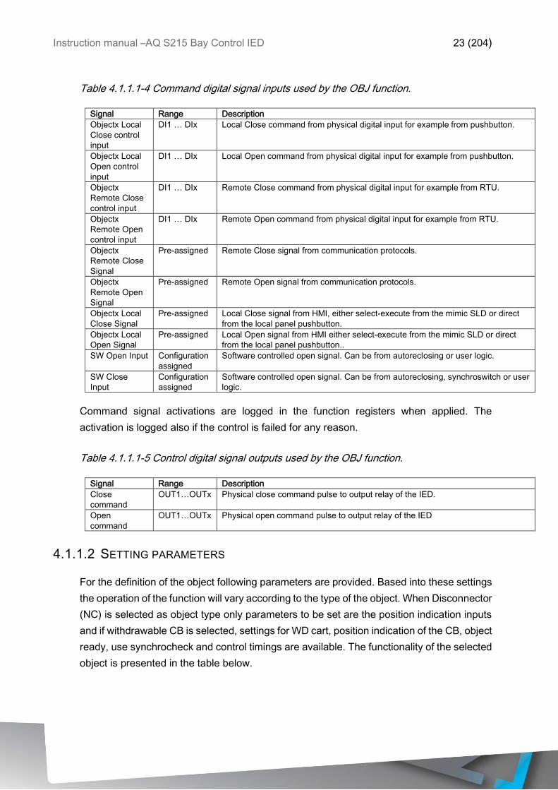
Instruction manual –AQ S215 Bay Control IED 23 (204)
Table 4.1.1.1-4 Command digital signal inputs used by the OBJ function.
Signal Range Description
Objectx Local
Close control
input
DI1 … DIx Local Close command from physical digital input for example from pushbutton.
Objectx Local
Open control
input
DI1 … DIx Local Open command from physical digital input for example from pushbutton.
Objectx
Remote Close
control input
DI1 … DIx Remote Close command from physical digital input for example from RTU.
Objectx
Remote Open
control input
DI1 … DIx Remote Open command from physical digital input for example from RTU.
Objectx
Remote Close
Signal
Pre-assigned Remote Close signal from communication protocols.
Objectx
Remote Open
Signal
Pre-assigned Remote Open signal from communication protocols.
Objectx Local
Close Signal
Pre-assigned Local Close signal from HMI, either select-execute from the mimic SLD or direct
from the local panel pushbutton.
Objectx Local
Open Signal
Pre-assigned Local Open signal from HMI either select-execute from the mimic SLD or direct
from the local panel pushbutton..
SW Open Input Configuration
assigned
Software controlled open signal. Can be from autoreclosing or user logic.
SW Close
Input
Configuration
assigned
Software controlled open signal. Can be from autoreclosing, synchroswitch or user
logic.
Command signal activations are logged in the function registers when applied. The
activation is logged also if the control is failed for any reason.
Table 4.1.1.1-5 Control digital signal outputs used by the OBJ function.
Signal Range Description
Close
command
OUT1…OUTx Physical close command pulse to output relay of the IED.
Open
command
OUT1…OUTx Physical open command pulse to output relay of the IED
4.1.1.2 SETTING PARAMETERS
For the definition of the object following parameters are provided. Based into these settings
the operation of the function will vary according to the type of the object. When Disconnector
(NC) is selected as object type only parameters to be set are the position indication inputs
and if withdrawable CB is selected, settings for WD cart, position indication of the CB, object
ready, use synchrocheck and control timings are available. The functionality of the selected
object is presented in the table below.
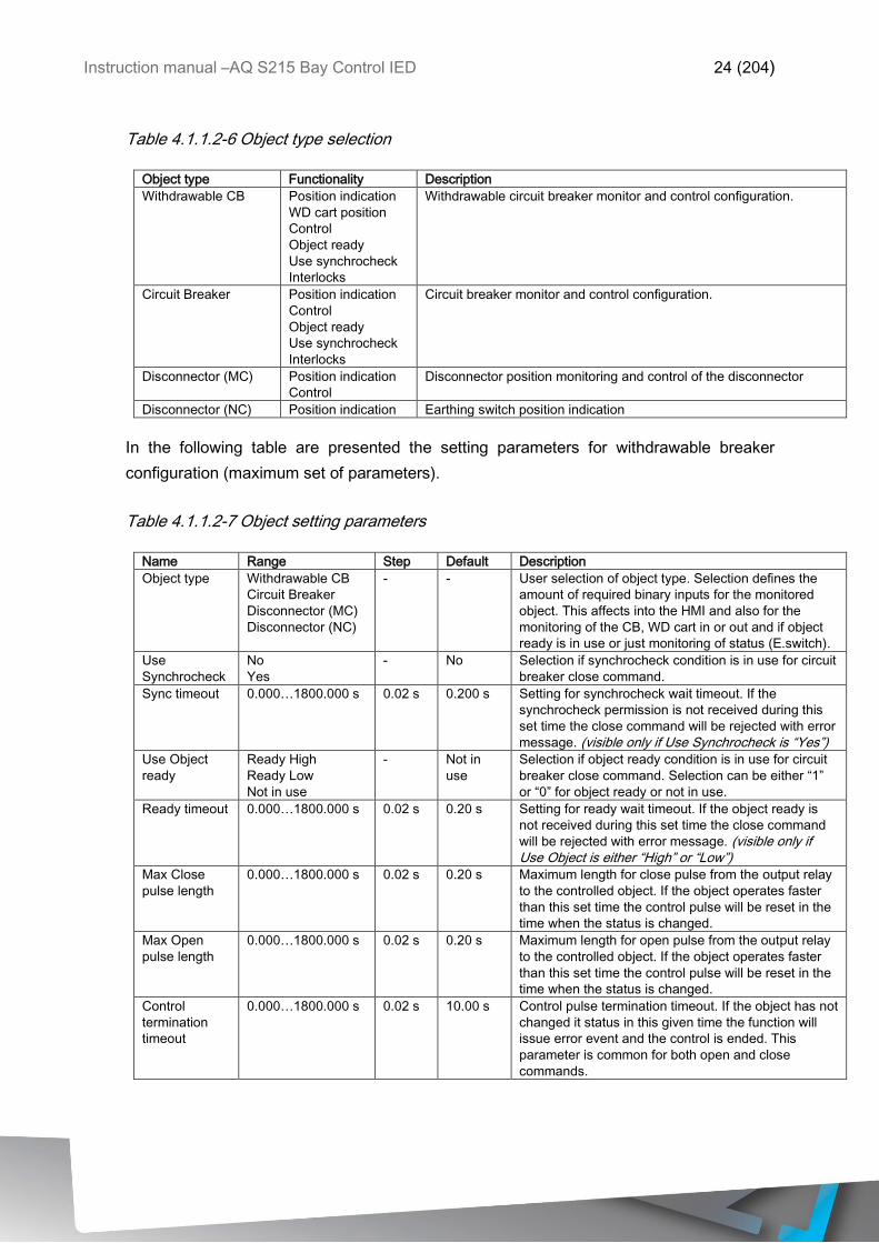
Instruction manual –AQ S215 Bay Control IED 24 (204)
Table 4.1.1.2-6 Object type selection
Object type Functionality Description
Withdrawable CB
Position indication
WD cart position
Control
Object ready
Use synchrocheck
Interlocks
Withdrawable circuit breaker monitor and control configuration.
Circuit Breaker
Position indication
Control
Object ready
Use synchrocheck
Interlocks
Circuit breaker monitor and control configuration.
Disconnector (MC)
Position indication
Control
Disconnector position monitoring and control of the disconnector
Disconnector (NC) Position indication Earthing switch position indication
In the following table are presented the setting parameters for withdrawable breaker
configuration (maximum set of parameters).
Table 4.1.1.2-7 Object setting parameters
Name Range Step Default Description
Object type Withdrawable CB
Circuit Breaker
Disconnector (MC)
Disconnector (NC)
- - User selection of object type. Selection defines the
amount of required binary inputs for the monitored
object. This affects into the HMI and also for the
monitoring of the CB, WD cart in or out and if object
ready is in use or just monitoring of status (E.switch).
Use
Synchrocheck
No
Yes
- No Selection if synchrocheck condition is in use for circuit
breaker close command.
Sync timeout 0.000…1800.000 s 0.02 s 0.200 s Setting for synchrocheck wait timeout. If the
synchrocheck permission is not received during this
set time the close command will be rejected with error
message. (visible only if Use Synchrocheck is “Yes”)
Use Object
ready
Ready High
Ready Low
Not in use
- Not in
use
Selection if object ready condition is in use for circuit
breaker close command. Selection can be either “1”
or “0” for object ready or not in use.
Ready timeout 0.000…1800.000 s 0.02 s 0.20 s Setting for ready wait timeout. If the object ready is
not received during this set time the close command
will be rejected with error message. (visible only if Use Object is either “High” or “Low”)
Max Close
pulse length
0.000…1800.000 s 0.02 s 0.20 s Maximum length for close pulse from the output relay
to the controlled object. If the object operates faster
than this set time the control pulse will be reset in the
time when the status is changed.
Max Open
pulse length
0.000…1800.000 s 0.02 s 0.20 s Maximum length for open pulse from the output relay
to the controlled object. If the object operates faster
than this set time the control pulse will be reset in the
time when the status is changed.
Control
termination
timeout
0.000…1800.000 s 0.02 s 10.00 s Control pulse termination timeout. If the object has not
changed it status in this given time the function will
issue error event and the control is ended. This
parameter is common for both open and close
commands.
Instruction manual –AQ S215 Bay Control IED 25 (204)
The pick-up activation of the function is not directly equal to start-signal generation of the
function. Start signal is allowed if blocking condition is not active.
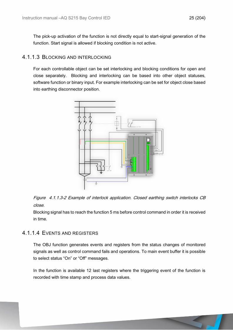
4.1.1.3 BLOCKING AND INTERLOCKING
For each controllable object can be set interlocking and blocking conditions for open and
close separately. Blocking and interlocking can be based into other object statuses,
software function or binary input. For example interlocking can be set for object close based
into earthing disconnector position.
Figure 4.1.1.3-2 Example of interlock application. Closed earthing switch interlocks CB
close.
Blocking signal has to reach the function 5 ms before control command in order it is received
in time.
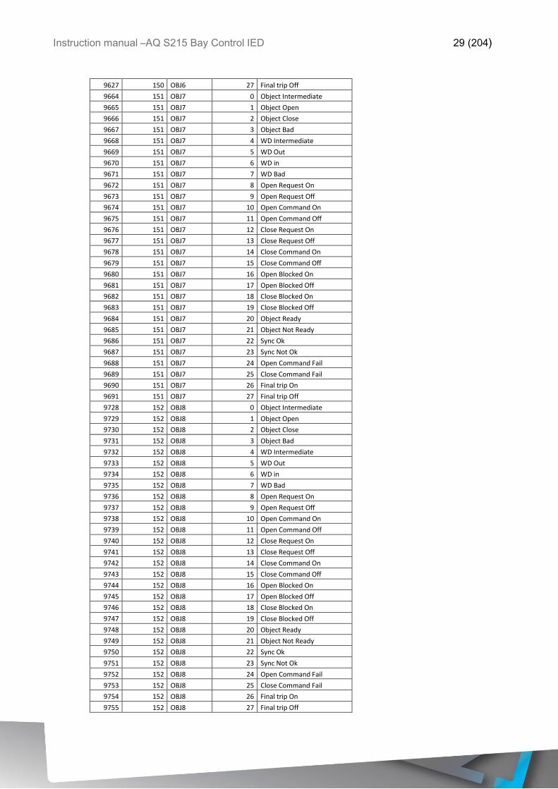
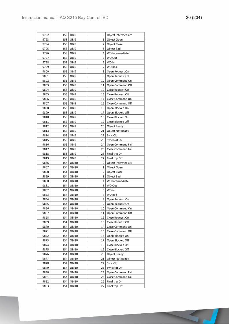
4.1.1.4 EVENTS AND REGISTERS
The OBJ function generates events and registers from the status changes of monitored
signals as well as control command fails and operations. To main event buffer it is possible
to select status “On” or “Off” messages.
In the function is available 12 last registers where the triggering event of the function is
recorded with time stamp and process data values.
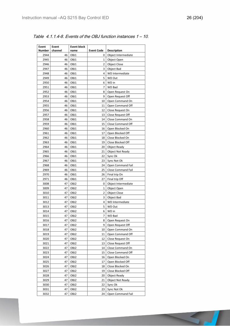
Instruction manual –AQ S215 Bay Control IED 26 (204)
Table 4.1.1.4-8. Events of the OBJ function instances 1 – 10.
Event Number
Event channel
Event block name Event Code Description
2944 46 OBJ1 0 Object Intermediate
2945 46 OBJ1 1 Object Open
2946 46 OBJ1 2 Object Close
2947 46 OBJ1 3 Object Bad
2948 46 OBJ1 4 WD Intermediate
2949 46 OBJ1 5 WD Out
2950 46 OBJ1 6 WD in
2951 46 OBJ1 7 WD Bad
2952 46 OBJ1 8 Open Request On
2953 46 OBJ1 9 Open Request Off
2954 46 OBJ1 10 Open Command On
2955 46 OBJ1 11 Open Command Off
2956 46 OBJ1 12 Close Request On
2957 46 OBJ1 13 Close Request Off
2958 46 OBJ1 14 Close Command On
2959 46 OBJ1 15 Close Command Off
2960 46 OBJ1 16 Open Blocked On
2961 46 OBJ1 17 Open Blocked Off
2962 46 OBJ1 18 Close Blocked On
2963 46 OBJ1 19 Close Blocked Off
2964 46 OBJ1 20 Object Ready
2965 46 OBJ1 21 Object Not Ready
2966 46 OBJ1 22 Sync Ok
2967 46 OBJ1 23 Sync Not Ok
2968 46 OBJ1 24 Open Command Fail
2969 46 OBJ1 25 Close Command Fail
2970 46 OBJ1 26 Final trip On
2971 46 OBJ1 27 Final trip Off
3008 47 OBJ2 0 Object Intermediate
3009 47 OBJ2 1 Object Open
3010 47 OBJ2 2 Object Close
3011 47 OBJ2 3 Object Bad
3012 47 OBJ2 4 WD Intermediate
3013 47 OBJ2 5 WD Out
3014 47 OBJ2 6 WD in
3015 47 OBJ2 7 WD Bad
3016 47 OBJ2 8 Open Request On
3017 47 OBJ2 9 Open Request Off
3018 47 OBJ2 10 Open Command On
3019 47 OBJ2 11 Open Command Off
3020 47 OBJ2 12 Close Request On
3021 47 OBJ2 13 Close Request Off
3022 47 OBJ2 14 Close Command On
3023 47 OBJ2 15 Close Command Off
3024 47 OBJ2 16 Open Blocked On
3025 47 OBJ2 17 Open Blocked Off
3026 47 OBJ2 18 Close Blocked On
3027 47 OBJ2 19 Close Blocked Off
3028 47 OBJ2 20 Object Ready
3029 47 OBJ2 21 Object Not Ready
3030 47 OBJ2 22 Sync Ok
3031 47 OBJ2 23 Sync Not Ok
3032 47 OBJ2 24 Open Command Fail

Instruction manual –AQ S215 Bay Control IED 27 (204)
3033 47 OBJ2 25 Close Command Fail
3034 47 OBJ2 26 Final trip On
3035 47 OBJ2 27 Final trip Off
3072 48 OBJ3 0 Object Intermediate
3073 48 OBJ3 1 Object Open
3074 48 OBJ3 2 Object Close
3075 48 OBJ3 3 Object Bad
3076 48 OBJ3 4 WD Intermediate
3077 48 OBJ3 5 WD Out
3078 48 OBJ3 6 WD in
3079 48 OBJ3 7 WD Bad
3080 48 OBJ3 8 Open Request On
3081 48 OBJ3 9 Open Request Off
3082 48 OBJ3 10 Open Command On
3083 48 OBJ3 11 Open Command Off
3084 48 OBJ3 12 Close Request On
3085 48 OBJ3 13 Close Request Off
3086 48 OBJ3 14 Close Command On
3087 48 OBJ3 15 Close Command Off
3088 48 OBJ3 16 Open Blocked On
3089 48 OBJ3 17 Open Blocked Off
3090 48 OBJ3 18 Close Blocked On
3091 48 OBJ3 19 Close Blocked Off
3092 48 OBJ3 20 Object Ready
3093 48 OBJ3 21 Object Not Ready
3094 48 OBJ3 22 Sync Ok
3095 48 OBJ3 23 Sync Not Ok
3096 48 OBJ3 24 Open Command Fail
3097 48 OBJ3 25 Close Command Fail
3098 48 OBJ3 26 Final trip On
3099 48 OBJ3 27 Final trip Off
3136 49 OBJ4 0 Object Intermediate
3137 49 OBJ4 1 Object Open
3138 49 OBJ4 2 Object Close
3139 49 OBJ4 3 Object Bad
3140 49 OBJ4 4 WD Intermediate
3141 49 OBJ4 5 WD Out
3142 49 OBJ4 6 WD in
3143 49 OBJ4 7 WD Bad
3144 49 OBJ4 8 Open Request On
3145 49 OBJ4 9 Open Request Off
3146 49 OBJ4 10 Open Command On
3147 49 OBJ4 11 Open Command Off
3148 49 OBJ4 12 Close Request On
3149 49 OBJ4 13 Close Request Off
3150 49 OBJ4 14 Close Command On
3151 49 OBJ4 15 Close Command Off
3152 49 OBJ4 16 Open Blocked On
3153 49 OBJ4 17 Open Blocked Off
3154 49 OBJ4 18 Close Blocked On
3155 49 OBJ4 19 Close Blocked Off
3156 49 OBJ4 20 Object Ready
3157 49 OBJ4 21 Object Not Ready
3158 49 OBJ4 22 Sync Ok
3159 49 OBJ4 23 Sync Not Ok
3160 49 OBJ4 24 Open Command Fail
3161 49 OBJ4 25 Close Command Fail

Instruction manual –AQ S215 Bay Control IED 28 (204)
3162 49 OBJ4 26 Final trip On
3163 49 OBJ4 27 Final trip Off
3200 50 OBJ5 0 Object Intermediate
3201 50 OBJ5 1 Object Open
3202 50 OBJ5 2 Object Close
3203 50 OBJ5 3 Object Bad
3204 50 OBJ5 4 WD Intermediate
3205 50 OBJ5 5 WD Out
3206 50 OBJ5 6 WD in
3207 50 OBJ5 7 WD Bad
3208 50 OBJ5 8 Open Request On
3209 50 OBJ5 9 Open Request Off
3210 50 OBJ5 10 Open Command On
3211 50 OBJ5 11 Open Command Off
3212 50 OBJ5 12 Close Request On
3213 50 OBJ5 13 Close Request Off
3214 50 OBJ5 14 Close Command On
3215 50 OBJ5 15 Close Command Off
3216 50 OBJ5 16 Open Blocked On
3217 50 OBJ5 17 Open Blocked Off
3218 50 OBJ5 18 Close Blocked On
3219 50 OBJ5 19 Close Blocked Off
3220 50 OBJ5 20 Object Ready
3221 50 OBJ5 21 Object Not Ready
3222 50 OBJ5 22 Sync Ok
3223 50 OBJ5 23 Sync Not Ok
3224 50 OBJ5 24 Open Command Fail
3225 50 OBJ5 25 Close Command Fail
3226 50 OBJ5 26 Final trip On
3227 50 OBJ5 27 Final trip Off
9600 150 OBJ6 0 Object Intermediate
9601 150 OBJ6 1 Object Open
9602 150 OBJ6 2 Object Close
9603 150 OBJ6 3 Object Bad
9604 150 OBJ6 4 WD Intermediate
9605 150 OBJ6 5 WD Out
9606 150 OBJ6 6 WD in
9607 150 OBJ6 7 WD Bad
9608 150 OBJ6 8 Open Request On
9609 150 OBJ6 9 Open Request Off
9610 150 OBJ6 10 Open Command On
9611 150 OBJ6 11 Open Command Off
9612 150 OBJ6 12 Close Request On
9613 150 OBJ6 13 Close Request Off
9614 150 OBJ6 14 Close Command On
9615 150 OBJ6 15 Close Command Off
9616 150 OBJ6 16 Open Blocked On
9617 150 OBJ6 17 Open Blocked Off
9618 150 OBJ6 18 Close Blocked On
9619 150 OBJ6 19 Close Blocked Off
9620 150 OBJ6 20 Object Ready
9621 150 OBJ6 21 Object Not Ready
9622 150 OBJ6 22 Sync Ok
9623 150 OBJ6 23 Sync Not Ok
9624 150 OBJ6 24 Open Command Fail
9625 150 OBJ6 25 Close Command Fail
9626 150 OBJ6 26 Final trip On
Instruction manual –AQ S215 Bay Control IED 29 (204)
9627 150 OBJ6 27 Final trip Off
9664 151 OBJ7 0 Object Intermediate
9665 151 OBJ7 1 Object Open
9666 151 OBJ7 2 Object Close
9667 151 OBJ7 3 Object Bad
9668 151 OBJ7 4 WD Intermediate
9669 151 OBJ7 5 WD Out
9670 151 OBJ7 6 WD in
9671 151 OBJ7 7 WD Bad
9672 151 OBJ7 8 Open Request On
9673 151 OBJ7 9 Open Request Off
9674 151 OBJ7 10 Open Command On
9675 151 OBJ7 11 Open Command Off
9676 151 OBJ7 12 Close Request On
9677 151 OBJ7 13 Close Request Off
9678 151 OBJ7 14 Close Command On
9679 151 OBJ7 15 Close Command Off
9680 151 OBJ7 16 Open Blocked On
9681 151 OBJ7 17 Open Blocked Off
9682 151 OBJ7 18 Close Blocked On
9683 151 OBJ7 19 Close Blocked Off
9684 151 OBJ7 20 Object Ready
9685 151 OBJ7 21 Object Not Ready
9686 151 OBJ7 22 Sync Ok
9687 151 OBJ7 23 Sync Not Ok
9688 151 OBJ7 24 Open Command Fail
9689 151 OBJ7 25 Close Command Fail
9690 151 OBJ7 26 Final trip On
9691 151 OBJ7 27 Final trip Off
9728 152 OBJ8 0 Object Intermediate
9729 152 OBJ8 1 Object Open
9730 152 OBJ8 2 Object Close
9731 152 OBJ8 3 Object Bad
9732 152 OBJ8 4 WD Intermediate
9733 152 OBJ8 5 WD Out
9734 152 OBJ8 6 WD in
9735 152 OBJ8 7 WD Bad
9736 152 OBJ8 8 Open Request On
9737 152 OBJ8 9 Open Request Off
9738 152 OBJ8 10 Open Command On
9739 152 OBJ8 11 Open Command Off
9740 152 OBJ8 12 Close Request On
9741 152 OBJ8 13 Close Request Off
9742 152 OBJ8 14 Close Command On
9743 152 OBJ8 15 Close Command Off
9744 152 OBJ8 16 Open Blocked On
9745 152 OBJ8 17 Open Blocked Off
9746 152 OBJ8 18 Close Blocked On
9747 152 OBJ8 19 Close Blocked Off
9748 152 OBJ8 20 Object Ready
9749 152 OBJ8 21 Object Not Ready
9750 152 OBJ8 22 Sync Ok
9751 152 OBJ8 23 Sync Not Ok
9752 152 OBJ8 24 Open Command Fail
9753 152 OBJ8 25 Close Command Fail
9754 152 OBJ8 26 Final trip On
9755 152 OBJ8 27 Final trip Off
Instruction manual –AQ S215 Bay Control IED 30 (204)
9792 153 OBJ9 0 Object Intermediate
9793 153 OBJ9 1 Object Open
9794 153 OBJ9 2 Object Close
9795 153 OBJ9 3 Object Bad
9796 153 OBJ9 4 WD Intermediate
9797 153 OBJ9 5 WD Out
9798 153 OBJ9 6 WD in
9799 153 OBJ9 7 WD Bad
9800 153 OBJ9 8 Open Request On
9801 153 OBJ9 9 Open Request Off
9802 153 OBJ9 10 Open Command On
9803 153 OBJ9 11 Open Command Off
9804 153 OBJ9 12 Close Request On
9805 153 OBJ9 13 Close Request Off
9806 153 OBJ9 14 Close Command On
9807 153 OBJ9 15 Close Command Off
9808 153 OBJ9 16 Open Blocked On
9809 153 OBJ9 17 Open Blocked Off
9810 153 OBJ9 18 Close Blocked On
9811 153 OBJ9 19 Close Blocked Off
9812 153 OBJ9 20 Object Ready
9813 153 OBJ9 21 Object Not Ready
9814 153 OBJ9 22 Sync Ok
9815 153 OBJ9 23 Sync Not Ok
9816 153 OBJ9 24 Open Command Fail
9817 153 OBJ9 25 Close Command Fail
9818 153 OBJ9 26 Final trip On
9819 153 OBJ9 27 Final trip Off
9856 154 OBJ10 0 Object Intermediate
9857 154 OBJ10 1 Object Open
9858 154 OBJ10 2 Object Close
9859 154 OBJ10 3 Object Bad
9860 154 OBJ10 4 WD Intermediate
9861 154 OBJ10 5 WD Out
9862 154 OBJ10 6 WD in
9863 154 OBJ10 7 WD Bad
9864 154 OBJ10 8 Open Request On
9865 154 OBJ10 9 Open Request Off
9866 154 OBJ10 10 Open Command On
9867 154 OBJ10 11 Open Command Off
9868 154 OBJ10 12 Close Request On
9869 154 OBJ10 13 Close Request Off
9870 154 OBJ10 14 Close Command On
9871 154 OBJ10 15 Close Command Off
9872 154 OBJ10 16 Open Blocked On
9873 154 OBJ10 17 Open Blocked Off
9874 154 OBJ10 18 Close Blocked On
9875 154 OBJ10 19 Close Blocked Off
9876 154 OBJ10 20 Object Ready
9877 154 OBJ10 21 Object Not Ready
9878 154 OBJ10 22 Sync Ok
9879 154 OBJ10 23 Sync Not Ok
9880 154 OBJ10 24 Open Command Fail
9881 154 OBJ10 25 Close Command Fail
9882 154 OBJ10 26 Final trip On
9883 154 OBJ10 27 Final trip Off
Instruction manual –AQ S215 Bay Control IED 31 (204)
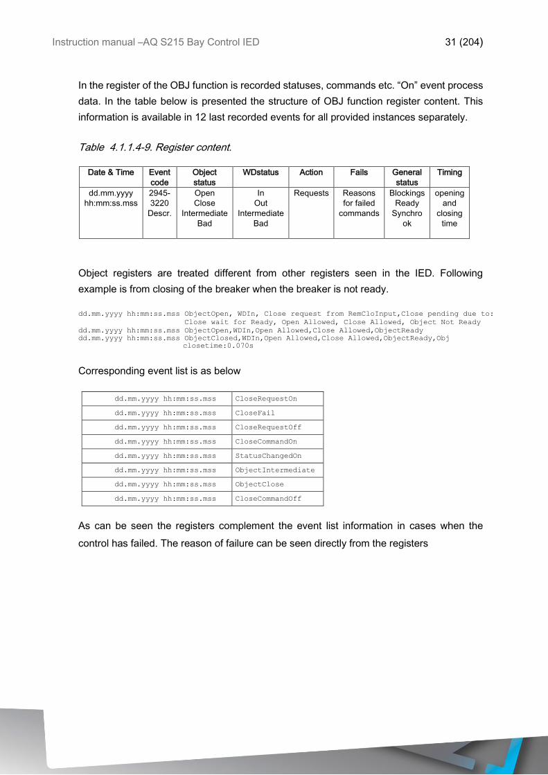
In the register of the OBJ function is recorded statuses, commands etc. “On” event process
data. In the table below is presented the structure of OBJ function register content. This
information is available in 12 last recorded events for all provided instances separately.
Table 4.1.1.4-9. Register content.
Date & Time Event
code
Object
status
WDstatus Action Fails General
status
Timing
dd.mm.yyyy
hh:mm:ss.mss
2945-
3220
Descr.
Open
Close
Intermediate
Bad
In
Out
Intermediate
Bad
Requests Reasons
for failed
commands
Blockings
Ready
Synchro
ok
opening
and
closing
time
Object registers are treated different from other registers seen in the IED. Following
example is from closing of the breaker when the breaker is not ready.
dd.mm.yyyy hh:mm:ss.mss ObjectOpen, WDIn, Close request from RemCloInput,Close pending due to:
Close wait for Ready, Open Allowed, Close Allowed, Object Not Ready
dd.mm.yyyy hh:mm:ss.mss ObjectOpen,WDIn,Open Allowed,Close Allowed,ObjectReady
dd.mm.yyyy hh:mm:ss.mss ObjectClosed,WDIn,Open Allowed,Close Allowed,ObjectReady,Obj
closetime:0.070s
Corresponding event list is as below
dd.mm.yyyy hh:mm:ss.mss CloseRequestOn
dd.mm.yyyy hh:mm:ss.mss CloseFail
dd.mm.yyyy hh:mm:ss.mss CloseRequestOff
dd.mm.yyyy hh:mm:ss.mss CloseCommandOn
dd.mm.yyyy hh:mm:ss.mss StatusChangedOn
dd.mm.yyyy hh:mm:ss.mss ObjectIntermediate
dd.mm.yyyy hh:mm:ss.mss ObjectClose
dd.mm.yyyy hh:mm:ss.mss CloseCommandOff
As can be seen the registers complement the event list information in cases when the
control has failed. The reason of failure can be seen directly from the registers

Instruction manual –AQ S215 Bay Control IED 32 (204)
4.1.2 INDICATOR OBJECT MONITORING (CIN)
Indicator function takes care of circuit breaker and disconnector status monitoring. Indicator
function is only for indication purposes which means it doesn’t have any control functionality.
For circuit breaker/disconnector controlling use objects. Monitoring is based into the
statuses of the configured IED binary inputs. In the relay the number of monitored indicators
is dependent of available IO. For status monitoring, typically 2 binary inputs are utilized per
monitored indicator. Alternatively, indicator status monitoring can be performed with single
digital input using rising and falling edge monitoring and logic virtual inputs. Selection of the
type of object is selected in the mimic editor.
Outputs of the function are monitored indicator statuses Open/Close. Setting parameters
are static inputs of the function which are changed only by user input in the setup phase of
the function.
Inputs for the function are binary status indications. The function generates general time
stamped ON/OFF events to the common event buffer from each of the open, close, bad
and intermediate event signals. Time stamp resolution is 1ms.
4.1.2.1 INPUT SIGNALS FOR INDICATOR STATUS MONITORING
Function uses available hardware and software digital signal statuses. These input signals
are also setting parameters for the function.
Table 4.1.2.1-10 Monitor digital signal inputs used by the CIN function.
Signal Range Description
IndicatorX
Open Input
DI1 … DIx
(SWx)
Link to the physical binary input. Monitored indicator OPEN status. “1” means
active open state of the monitored indicator. Position indication can be done
among binary inputs and protection stage signals by using IEC-61850, GOOSE or
logical signals.
IndicatorX
Close Input
DI1 … Dix
(SWx)
Link to the physical binary input. Monitored indicator CLOSE status. “1” means
active close state of the monitored indicator. Position indication can be done
among binary inputs and protection stage signals by using IEC-61850, GOOSE or
logical signals.
Status change of the signals will always cause recorded event also in the indicators
continuous status indications. Events can be enabled or disabled according to the
application requirements.
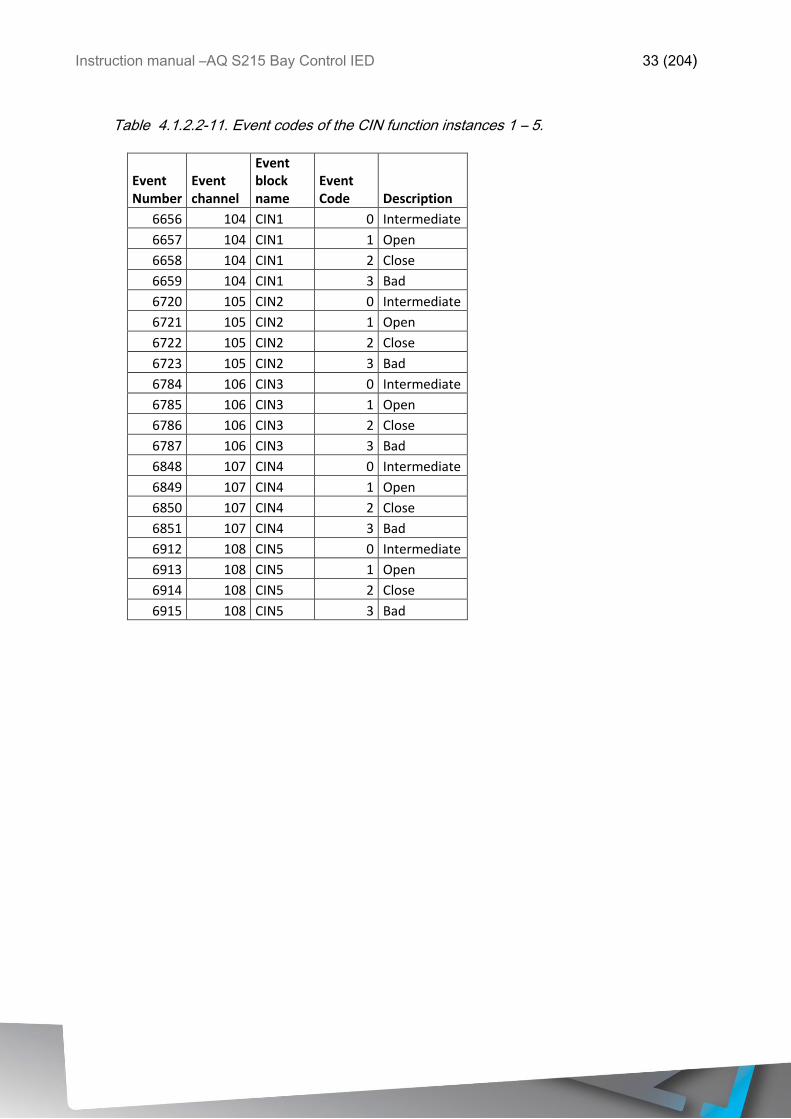
4.1.2.2 EVENTS
The indicator function generates events and registers from the status changes of monitored
signals. To main event buffer is possible to select status “On” or “Off” messages.
Instruction manual –AQ S215 Bay Control IED 33 (204)
Table 4.1.2.2-11. Event codes of the CIN function instances 1 – 5.
Event Number
Event channel
Event block name
Event Code Description
6656 104 CIN1 0 Intermediate
6657 104 CIN1 1 Open
6658 104 CIN1 2 Close
6659 104 CIN1 3 Bad
6720 105 CIN2 0 Intermediate
6721 105 CIN2 1 Open
6722 105 CIN2 2 Close
6723 105 CIN2 3 Bad
6784 106 CIN3 0 Intermediate
6785 106 CIN3 1 Open
6786 106 CIN3 2 Close
6787 106 CIN3 3 Bad
6848 107 CIN4 0 Intermediate
6849 107 CIN4 1 Open
6850 107 CIN4 2 Close
6851 107 CIN4 3 Bad
6912 108 CIN5 0 Intermediate
6913 108 CIN5 1 Open
6914 108 CIN5 2 Close
6915 108 CIN5 3 Bad
Instruction manual –AQ S215 Bay Control IED 34 (204)
4.1.3 PROGRAMMABLE CONTROL SWITCH
Programmable Control Switch is a control function that controls its binary output signal
on/off. This output signal can be controlled locally from the IED mimic (appears as square
box) or remotely from RTU. Programmable Control Switches main purpose is to change
function properties by changing the setting group by other means or block/enable functions.
This binary signal can be also used for any other kind of purpose just like all other binary
signals.
Once Programmable Control Switch output has been activated (1) or disabled (0) it will
remain in this state until given a new control command to the opposite state. The switch
cannot be controlled by any “auxiliary” input like digital input or logic signals, only local mimic
control or remote RTU control are available.
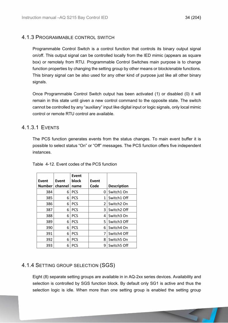
4.1.3.1 EVENTS
The PCS function generates events from the status changes. To main event buffer it is
possible to select status “On” or “Off” messages. The PCS function offers five independent
instances.
Table 4-12. Event codes of the PCS function
Event Number
Event channel
Event block name
Event Code Description
384 6 PCS 0 Switch1 On
385 6 PCS 1 Switch1 Off
386 6 PCS 2 Switch2 On
387 6 PCS 3 Switch2 Off
388 6 PCS 4 Switch3 On
389 6 PCS 5 Switch3 Off
390 6 PCS 6 Switch4 On
391 6 PCS 7 Switch4 Off
392 6 PCS 8 Switch5 On
393 6 PCS 9 Switch5 Off
4.1.4 SETTING GROUP SELECTION (SGS)
Eight (8) separate setting groups are available in in AQ-2xx series devices. Availability and
selection is controlled by SGS function block. By default only SG1 is active and thus the
selection logic is idle. When more than one setting group is enabled the setting group
Instruction manual –AQ S215 Bay Control IED 35 (204)
selector logic shall take control of the setting group activations based into the user
programmed logic and conditions.
Setting group activation for use in the application is set in the SGS function block which
after all available functions enable corresponding setting groups. If setting group is not
activated but is tried to control on with SGS an event of failed setting group change is issued.
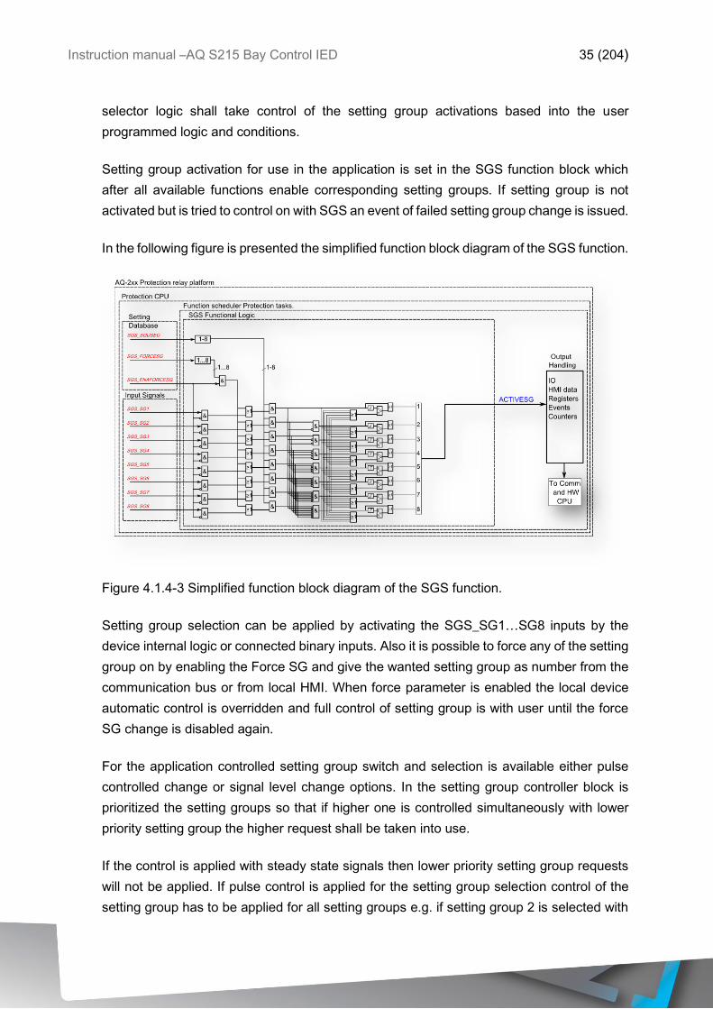
In the following figure is presented the simplified function block diagram of the SGS function.
Figure 4.1.4-3 Simplified function block diagram of the SGS function.
Setting group selection can be applied by activating the SGS_SG1…SG8 inputs by the
device internal logic or connected binary inputs. Also it is possible to force any of the setting
group on by enabling the Force SG and give the wanted setting group as number from the
communication bus or from local HMI. When force parameter is enabled the local device
automatic control is overridden and full control of setting group is with user until the force
SG change is disabled again.
For the application controlled setting group switch and selection is available either pulse
controlled change or signal level change options. In the setting group controller block is
prioritized the setting groups so that if higher one is controlled simultaneously with lower
priority setting group the higher request shall be taken into use.
If the control is applied with steady state signals then lower priority setting group requests
will not be applied. If pulse control is applied for the setting group selection control of the
setting group has to be applied for all setting groups e.g. if setting group 2 is selected with
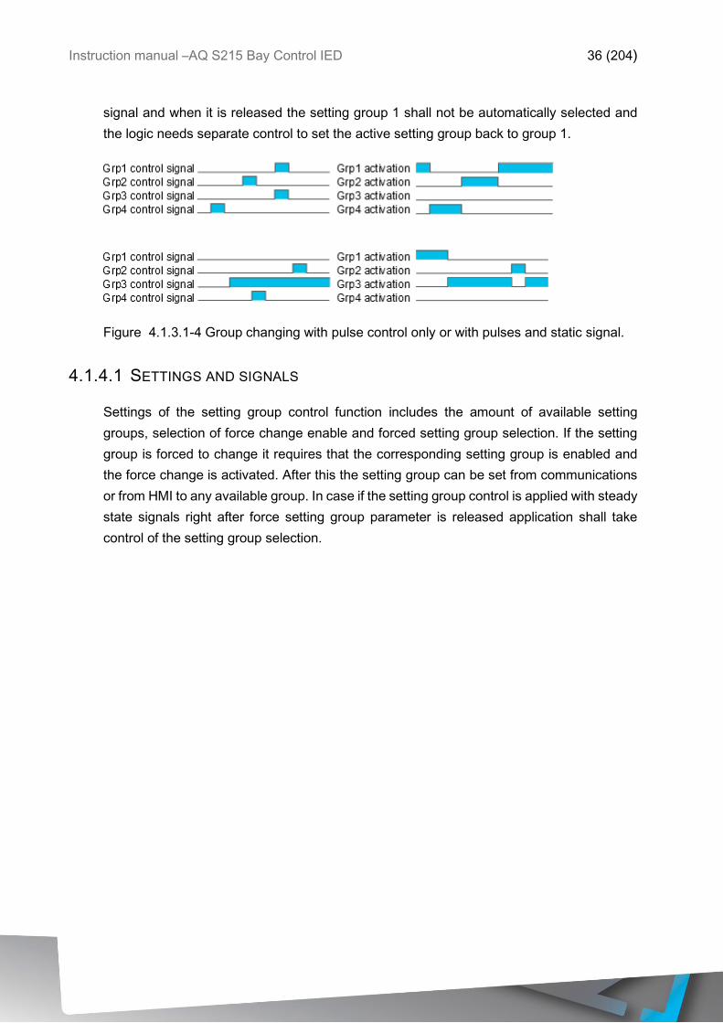
Instruction manual –AQ S215 Bay Control IED 36 (204)
signal and when it is released the setting group 1 shall not be automatically selected and
the logic needs separate control to set the active setting group back to group 1.
Figure 4.1.3.1-4 Group changing with pulse control only or with pulses and static signal.
4.1.4.1 SETTINGS AND SIGNALS
Settings of the setting group control function includes the amount of available setting
groups, selection of force change enable and forced setting group selection. If the setting
group is forced to change it requires that the corresponding setting group is enabled and
the force change is activated. After this the setting group can be set from communications
or from HMI to any available group. In case if the setting group control is applied with steady
state signals right after force setting group parameter is released application shall take
control of the setting group selection.
Instruction manual –AQ S215 Bay Control IED 37 (204)
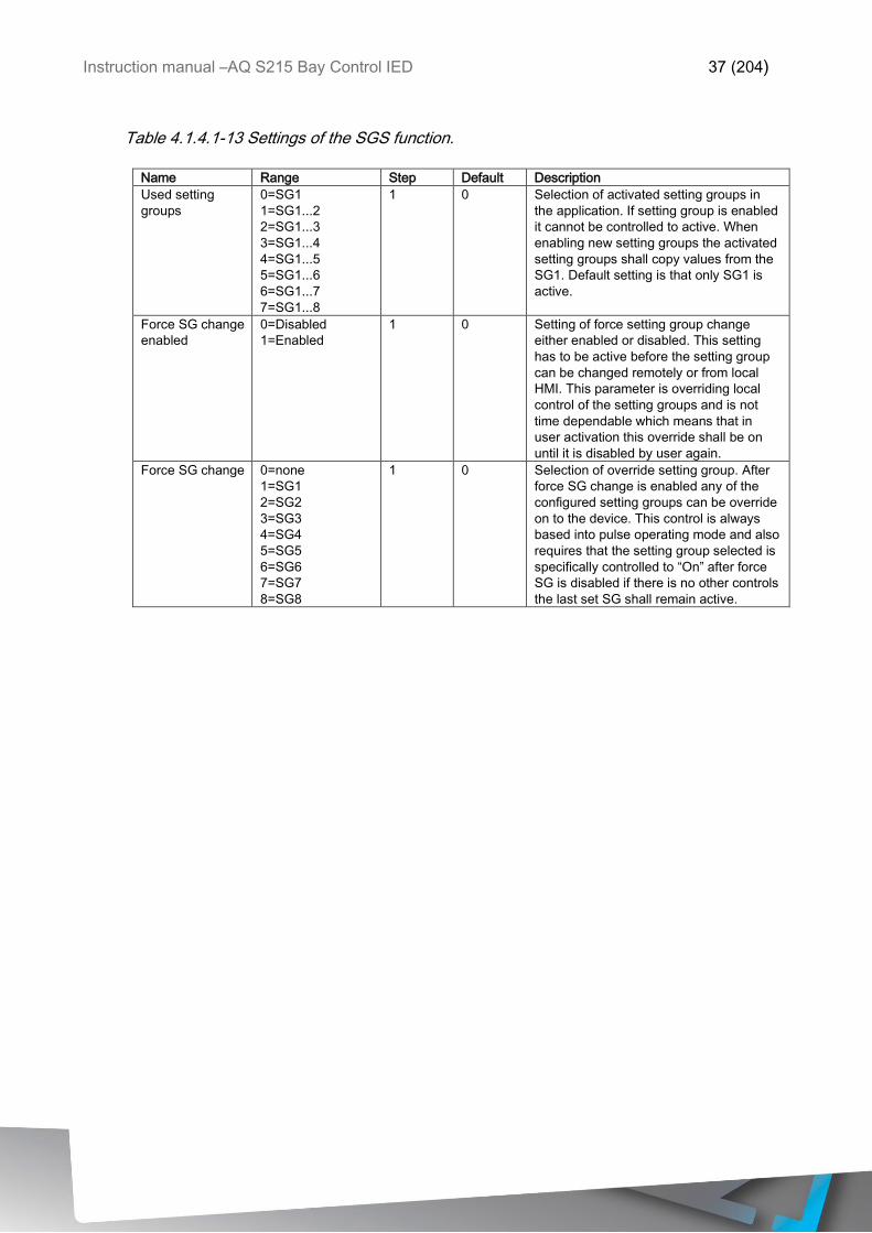
Table 4.1.4.1-13 Settings of the SGS function.
Name Range Step Default Description
Used setting
groups
0=SG1
1=SG1...2
2=SG1...3
3=SG1...4
4=SG1...5
5=SG1...6
6=SG1...7
7=SG1...8
1 0 Selection of activated setting groups in
the application. If setting group is enabled
it cannot be controlled to active. When
enabling new setting groups the activated
setting groups shall copy values from the
SG1. Default setting is that only SG1 is
active.
Force SG change
enabled
0=Disabled
1=Enabled
1 0 Setting of force setting group change
either enabled or disabled. This setting
has to be active before the setting group
can be changed remotely or from local
HMI. This parameter is overriding local
control of the setting groups and is not
time dependable which means that in
user activation this override shall be on
until it is disabled by user again.
Force SG change 0=none
1=SG1
2=SG2
3=SG3
4=SG4
5=SG5
6=SG6
7=SG7
8=SG8
1 0 Selection of override setting group. After
force SG change is enabled any of the
configured setting groups can be override
on to the device. This control is always
based into pulse operating mode and also
requires that the setting group selected is
specifically controlled to “On” after force
SG is disabled if there is no other controls
the last set SG shall remain active.
Instruction manual –AQ S215 Bay Control IED 38 (204)
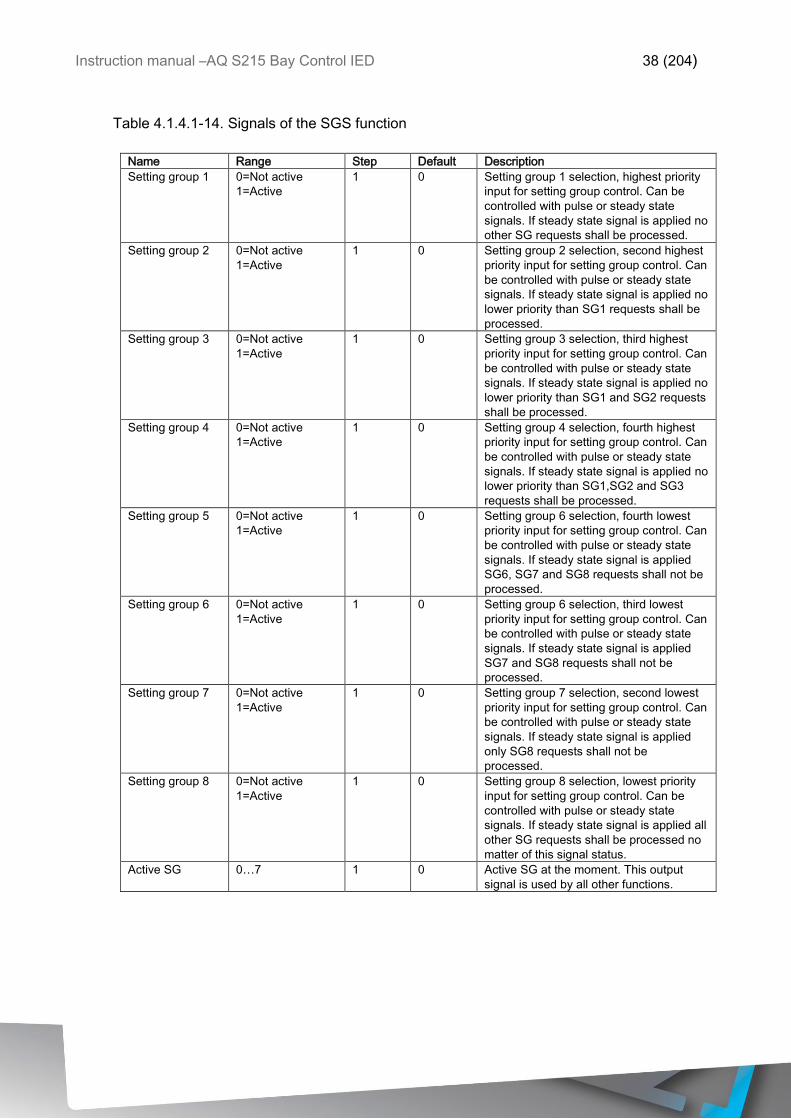
Table 4.1.4.1-14. Signals of the SGS function
Name Range Step Default Description
Setting group 1 0=Not active
1=Active
1 0 Setting group 1 selection, highest priority
input for setting group control. Can be
controlled with pulse or steady state
signals. If steady state signal is applied no
other SG requests shall be processed.
Setting group 2 0=Not active
1=Active
1 0 Setting group 2 selection, second highest
priority input for setting group control. Can
be controlled with pulse or steady state
signals. If steady state signal is applied no
lower priority than SG1 requests shall be
processed.
Setting group 3 0=Not active
1=Active
1 0 Setting group 3 selection, third highest
priority input for setting group control. Can
be controlled with pulse or steady state
signals. If steady state signal is applied no
lower priority than SG1 and SG2 requests
shall be processed.
Setting group 4 0=Not active
1=Active
1 0 Setting group 4 selection, fourth highest
priority input for setting group control. Can
be controlled with pulse or steady state
signals. If steady state signal is applied no
lower priority than SG1,SG2 and SG3
requests shall be processed.
Setting group 5 0=Not active
1=Active
1 0 Setting group 6 selection, fourth lowest
priority input for setting group control. Can
be controlled with pulse or steady state
signals. If steady state signal is applied
SG6, SG7 and SG8 requests shall not be
processed.
Setting group 6 0=Not active
1=Active
1 0 Setting group 6 selection, third lowest
priority input for setting group control. Can
be controlled with pulse or steady state
signals. If steady state signal is applied
SG7 and SG8 requests shall not be
processed.
Setting group 7 0=Not active
1=Active
1 0 Setting group 7 selection, second lowest
priority input for setting group control. Can
be controlled with pulse or steady state
signals. If steady state signal is applied
only SG8 requests shall not be
processed.
Setting group 8 0=Not active
1=Active
1 0 Setting group 8 selection, lowest priority
input for setting group control. Can be
controlled with pulse or steady state
signals. If steady state signal is applied all
other SG requests shall be processed no
matter of this signal status.
Active SG 0…7 1 0 Active SG at the moment. This output
signal is used by all other functions.
Instruction manual –AQ S215 Bay Control IED 39 (204)
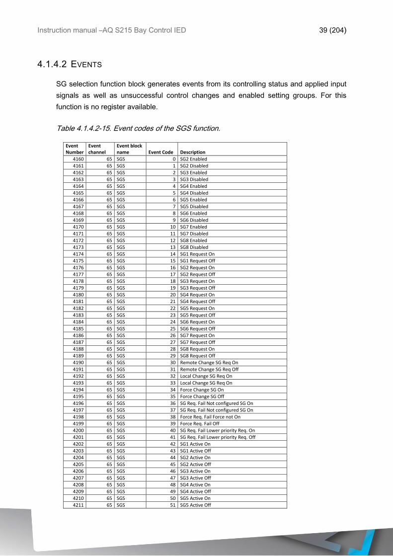
4.1.4.2 EVENTS
SG selection function block generates events from its controlling status and applied input
signals as well as unsuccessful control changes and enabled setting groups. For this
function is no register available.
Table 4.1.4.2-15. Event codes of the SGS function.
Event Number
Event channel
Event block name Event Code Description
4160 65 SGS 0 SG2 Enabled
4161 65 SGS 1 SG2 Disabled
4162 65 SGS 2 SG3 Enabled
4163 65 SGS 3 SG3 Disabled
4164 65 SGS 4 SG4 Enabled
4165 65 SGS 5 SG4 Disabled
4166 65 SGS 6 SG5 Enabled
4167 65 SGS 7 SG5 Disabled
4168 65 SGS 8 SG6 Enabled
4169 65 SGS 9 SG6 Disabled
4170 65 SGS 10 SG7 Enabled
4171 65 SGS 11 SG7 Disabled
4172 65 SGS 12 SG8 Enabled
4173 65 SGS 13 SG8 Disabled
4174 65 SGS 14 SG1 Request On
4175 65 SGS 15 SG1 Request Off
4176 65 SGS 16 SG2 Request On
4177 65 SGS 17 SG2 Request Off
4178 65 SGS 18 SG3 Request On
4179 65 SGS 19 SG3 Request Off
4180 65 SGS 20 SG4 Request On
4181 65 SGS 21 SG4 Request Off
4182 65 SGS 22 SG5 Request On
4183 65 SGS 23 SG5 Request Off
4184 65 SGS 24 SG6 Request On
4185 65 SGS 25 SG6 Request Off
4186 65 SGS 26 SG7 Request On
4187 65 SGS 27 SG7 Request Off
4188 65 SGS 28 SG8 Request On
4189 65 SGS 29 SG8 Request Off
4190 65 SGS 30 Remote Change SG Req On
4191 65 SGS 31 Remote Change SG Req Off
4192 65 SGS 32 Local Change SG Req On
4193 65 SGS 33 Local Change SG Req On
4194 65 SGS 34 Force Change SG On
4195 65 SGS 35 Force Change SG Off
4196 65 SGS 36 SG Req. Fail Not configured SG On
4197 65 SGS 37 SG Req. Fail Not configured SG On
4198 65 SGS 38 Force Req. Fail Force not On
4199 65 SGS 39 Force Req. Fail Off
4200 65 SGS 40 SG Req. Fail Lower priority Req. On
4201 65 SGS 41 SG Req. Fail Lower priority Req. Off
4202 65 SGS 42 SG1 Active On
4203 65 SGS 43 SG1 Active Off
4204 65 SGS 44 SG2 Active On
4205 65 SGS 45 SG2 Active Off
4206 65 SGS 46 SG3 Active On
4207 65 SGS 47 SG3 Active Off
4208 65 SGS 48 SG4 Active On
4209 65 SGS 49 SG4 Active Off
4210 65 SGS 50 SG5 Active On
4211 65 SGS 51 SG5 Active Off

Instruction manual –AQ S215 Bay Control IED 40 (204)
4212 65 SGS 52 SG6 Active On
4213 65 SGS 53 SG6 Active Off
4214 65 SGS 54 SG7 Active On
4215 65 SGS 55 SG7 Active Off
4216 65 SGS 56 SG8 Active On
4217 65 SGS 57 SG8 Active Off
4.1.4.3 EXAMPLES OF SETTING GROUP CONTROL
In this chapter are presented some of most common applications for setting group changing
requirements.
In a Petersen coil compensated network is usually used directional sensitive earth fault
protection which characteristics is wanted to be controlled in between Varmetric and
Wattmetric based into if the Petersen coil is connected when the network is compensated
or is it open when the network is unearthed.
Figure 4.1.4.3-5 Setting group control with 1 wire connection from Petersen coil status.
By monitoring the state of the Petersen coil connection the setting group control can be
applied either with 1 wire or 2 wire connection depending of the application requirements.
In case of 1 wire connection is allowed the setting group change logic can be applied as in
the figure above. Petersen coil status on controls SG1 to be active and if the coil is
disconnected SG2 is active. With this practice if the wire is broken for some reason the
setting group would always be controlled to SG2.
Instruction manual –AQ S215 Bay Control IED 41 (204)
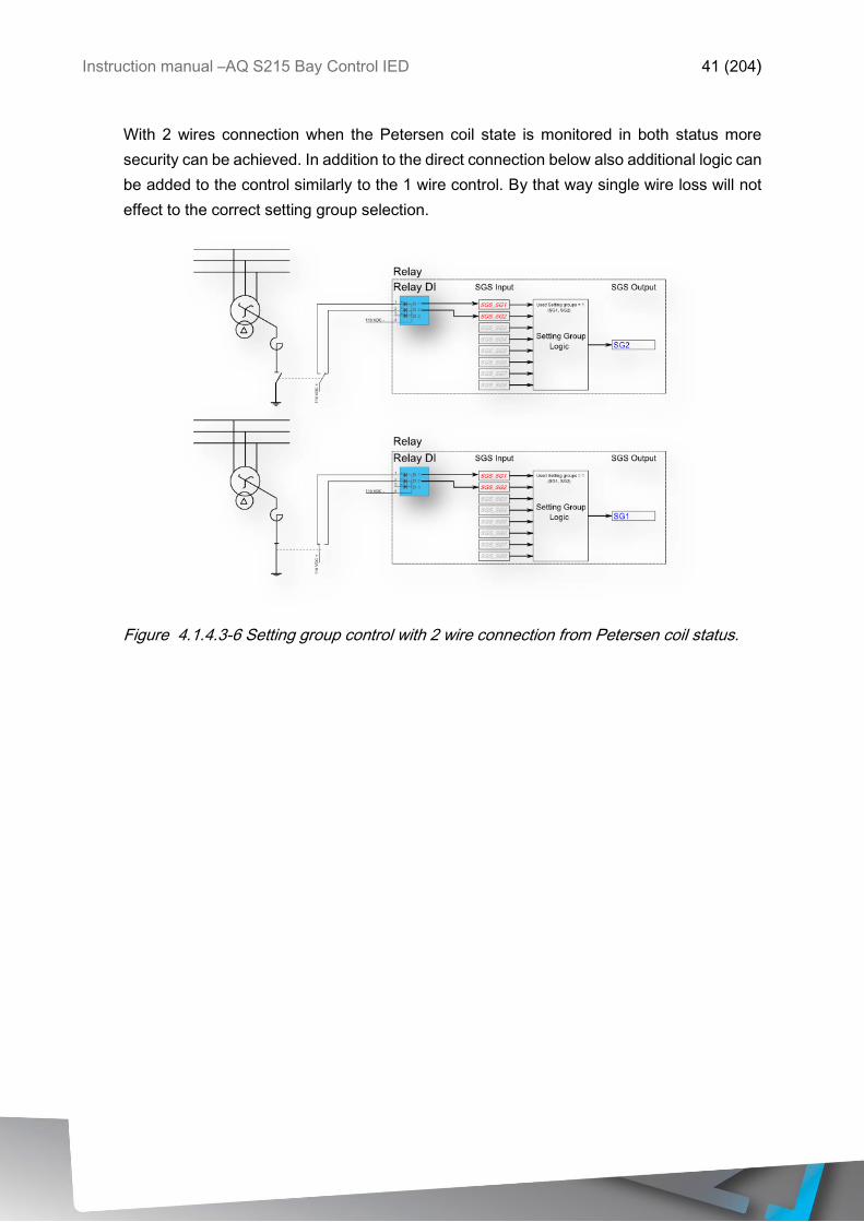
With 2 wires connection when the Petersen coil state is monitored in both status more
security can be achieved. In addition to the direct connection below also additional logic can
be added to the control similarly to the 1 wire control. By that way single wire loss will not
effect to the correct setting group selection.
Figure 4.1.4.3-6 Setting group control with 2 wire connection from Petersen coil status.
Instruction manual –AQ S215 Bay Control IED 42 (204)
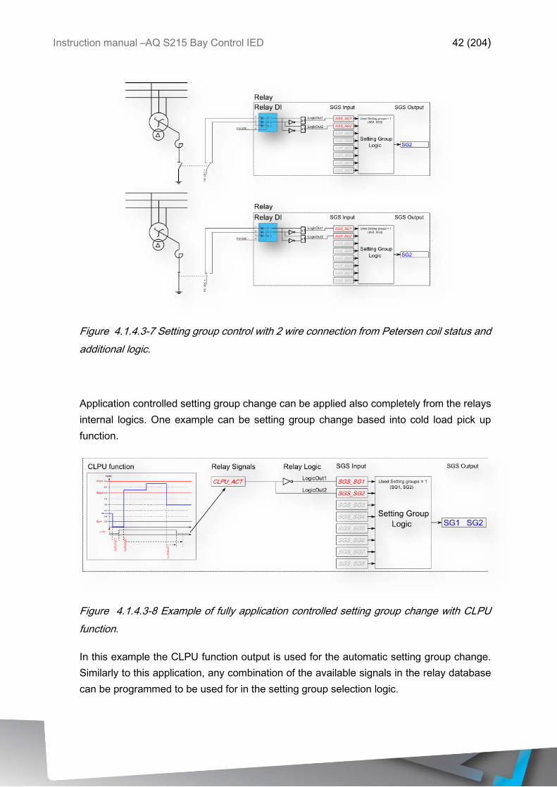
Figure 4.1.4.3-7 Setting group control with 2 wire connection from Petersen coil status and
additional logic.
Application controlled setting group change can be applied also completely from the relays
internal logics. One example can be setting group change based into cold load pick up
function.
Figure 4.1.4.3-8 Example of fully application controlled setting group change with CLPU
function.
In this example the CLPU function output is used for the automatic setting group change.
Similarly to this application, any combination of the available signals in the relay database
can be programmed to be used for in the setting group selection logic.
Instruction manual –AQ S215 Bay Control IED 43 (204)
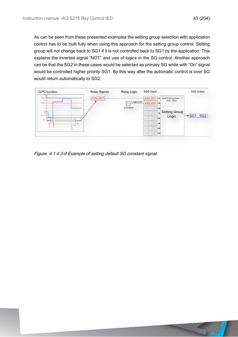
As can be seen from these presented examples the setting group selection with application
control has to be built fully when using this approach for the setting group control. Setting
group will not change back to SG1 if it is not controlled back to SG1 by the application. This
explains the inverted signal “NOT” and use of logics in the SG control. Another approach
can be that the SG2 in these cases would be selected as primary SG while with “On” signal
would be controlled higher priority SG1. By this way after the automatic control is over SG
would return automatically to SG2.
Figure 4.1.4.3-9 Example of setting default SG constant signal.
Instruction manual –AQ S215 Bay Control IED 44 (204)
4.1.5 AUTO-RECLOSING 0 1 (79)
Autoreclosing (AR) means coordinated de-energization and energization of transmission or
distribution overhead-line with purpose to clear permanent or semi-permanent cause of fault
from the line to restore supply automatically to the line.
Autoreclosing can be used in overhead-line networks for clearing transient and semi-
permanent faults which present approximately 80-95% of all of the faults found in
transmission and distribution networks. Majority of this type of faults can be cleared with
high speed autoreclosing and the rest of the faults can be cleared with delayed
autoreclosing by de-energizing the faulty line for a longer period of time.
Only minority of the overhead line faults are permanent type which require maintenance or
repair in the actual fault location. Faults like lightning in the line, tree branch touching to the
overhead line, arc caused by animals or short circuits caused by objects touching to the
overhead lines are this type of transient and semi-permanent faults. If the fault is permanent
for example tree fall and leaning into the overhead line or broken insulator, autoreclosing
will not clear the fault and the faulty feeder shall be locked from closing until the cause of
the fault is repaired in the actual fault location. Also close short circuit faults should avoid
the autoreclosing to be even initiated in order to avoid unnecessary stress for the lines and
circuit breaker in cases when the fault cannot be cleared by autoreclosing the line. Similar
situations arise also in the mixed cable and overhead line networks since cable network
faults cannot be cleared by autoreclosing. In this category faults the autorecloser should be
aware of fault location before autoreclosing is applied to the faulty line.
4.1.5.1 AUTORECLOSING AS APPLICATION
The main principle of autoreclosing is to de-energize the faulty line and fault location so that
the cause of the fault can drop out from the line. When the line is energized and object
either touches or drops into the line, current will start to flow through the object either to the
ground or in between of the phases causing the surrounding air to heat and ionize and start
to operate as conductor in between of the energized phase(s) and (or) ground causing arc
to ignite.
When the breaker is opened either by command of autorecloser or protection function,
voltage in the line will be zero thus extinguishing the arc and letting the object which caused
the fault to drop from the line and by this way clearing the cause of the fault. Autorecloser
closes the breaker after set time (called Dead Time meaning the time which the line is not-
energized) and the supply is restored to the line. If the fault is not cleared by this first
autoreclosing cycle (called Shot) then more shots can be applied to the line.

Instruction manual –AQ S215 Bay Control IED 45 (204)
If the fault was not cleared by the time autorecloser closes the breaker and second shot is
applied into the line there can be set either time delay (called Arcing time) in order to burn
the fault causing object from the line or normal protection operating times can be applied.
In autorecloser is selection also if the fault is not present when closing the breaker but
reappears soon after closing the breaker (called Discrimination time, Reclaim time),
Autorecloser either arms another shot or gives final trip command and locks-out. In case
one shot is applied to the line and if it is not successfully clearing the fault autorecloser will
init final trip and will lock out the feeder closing also.
Whether single or multi-shot autoreclosing should be used is matter of the type of protection,
switchgear, circuit breaker, stability requirements, network type, consumer loads and also
local utility knowledge and practices of the network.
Typical autoreclosing scheme is not easy to define since in distribution and transmission
networks these mentioned parameters vary greatly thus affecting directly to the scheme
main parameters, how many shots and how long dead times should be set for the reclosing
scheme and also which protection functions should init the autorecloser.
Minimum times for the Dead Time setting is mostly dependent of the voltage level of the
protected network in order to give enough time for the air to de-ionize after the circuit
breaker is opened. For medium voltage 20 kV to 75 kV Dead Time of 200 ms should be
sufficient when for 110 kV requires about 300 ms and 400 kV requires 400-500 ms Dead
Time. This minimum time is not this straightforward to define since it is affected by other
parameters also like conductor spacing, wind speed, fault type, fault duration etc. The main
purpose of the Dead Time is to allow and give time for the fault location surrounding air to
return to isolating state before the line is re-energized and inhibit the arc from re-ignite due
to heated and ionized air. Also for lower voltage levels the breaker open-close-open cycle
capacity gives restrictions for the minimum Dead Time setting while with higher voltage
levels the de-ionizing time dictates the minimum Dead Time which makes possible a
successful autoreclosing.
In case of evolving faults like transient earth fault turns to multi-phase short circuit or
overcurrent fault different schemes can be built by setting the requests into different
priorities and behaviors. Autorecloser has five independent priority requests for reclosing
and one critical request which halt the recloser in any position it is running when the critical
request is received. REQ1 has the highest priority and REQ5 lowest.
Instruction manual –AQ S215 Bay Control IED 46 (204)
4.1.5.2 AUTORECLOSING SCHEME IN RADIAL NETWORK
In typical medium voltage overhead network construction is radial type and does not cause
any additional requirements for the autoreclosing scheme in addition to the mentioned air
de-ionization time and the capacity of the circuit breaker which should be the dictating
magnitudes for the autoreclosing scheme. Also typically medium voltage overhead line
consists of only consumers and no power generation which leads to that the most stable
supply continuity is the main objective.
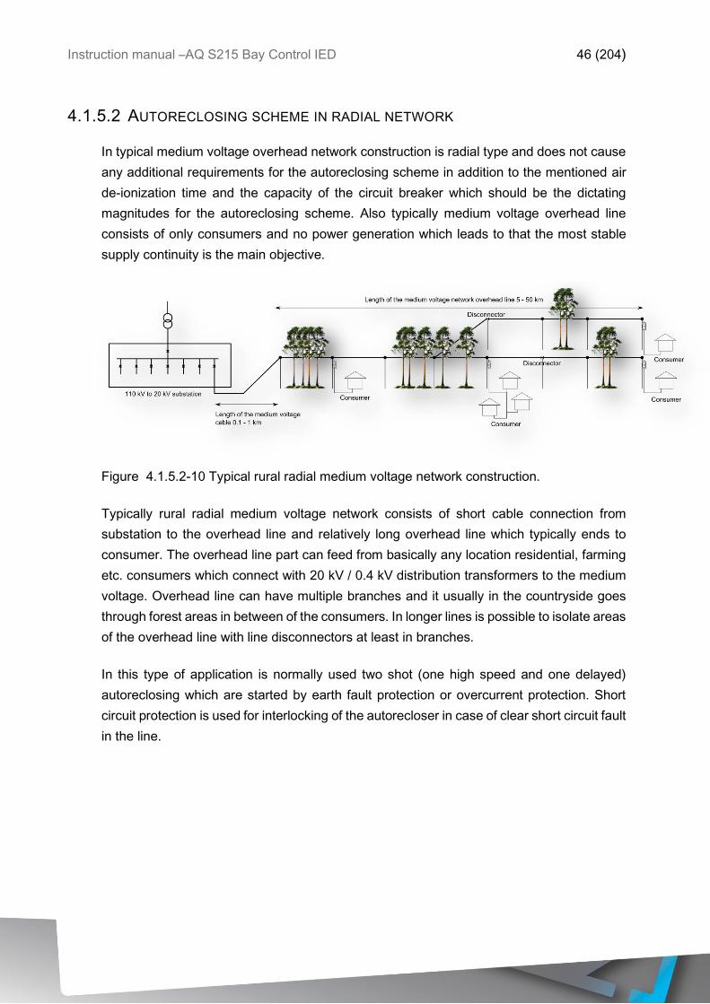
Figure 4.1.5.2-10 Typical rural radial medium voltage network construction.
Typically rural radial medium voltage network consists of short cable connection from
substation to the overhead line and relatively long overhead line which typically ends to
consumer. The overhead line part can feed from basically any location residential, farming
etc. consumers which connect with 20 kV / 0.4 kV distribution transformers to the medium
voltage. Overhead line can have multiple branches and it usually in the countryside goes
through forest areas in between of the consumers. In longer lines is possible to isolate areas
of the overhead line with line disconnectors at least in branches.
In this type of application is normally used two shot (one high speed and one delayed)
autoreclosing which are started by earth fault protection or overcurrent protection. Short
circuit protection is used for interlocking of the autorecloser in case of clear short circuit fault
in the line.
Instruction manual –AQ S215 Bay Control IED 47 (204)
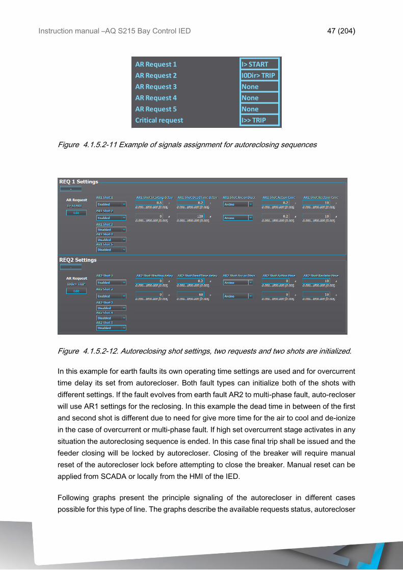
Figure 4.1.5.2-11 Example of signals assignment for autoreclosing sequences
Figure 4.1.5.2-12. Autoreclosing shot settings, two requests and two shots are initialized.
In this example for earth faults its own operating time settings are used and for overcurrent
time delay its set from autorecloser. Both fault types can initialize both of the shots with
different settings. If the fault evolves from earth fault AR2 to multi-phase fault, auto-recloser
will use AR1 settings for the reclosing. In this example the dead time in between of the first
and second shot is different due to need for give more time for the air to cool and de-ionize
in the case of overcurrent or multi-phase fault. If high set overcurrent stage activates in any
situation the autoreclosing sequence is ended. In this case final trip shall be issued and the
feeder closing will be locked by autorecloser. Closing of the breaker will require manual
reset of the autorecloser lock before attempting to close the breaker. Manual reset can be
applied from SCADA or locally from the HMI of the IED.
Following graphs present the principle signaling of the autorecloser in different cases
possible for this type of line. The graphs describe the available requests status, autorecloser
AR Request 1 I> START
AR Request 2 I0Dir> TRIP
AR Request 3 None
AR Request 4 None
AR Request 5 None
Critical request I>> TRIP
Instruction manual –AQ S215 Bay Control IED 48 (204)
internal signal statuses, timer statuses, breaker controls from autorecloser and breaker
status signals.
Autorecloser operates closely with Object control and all of the breaker status and monitor
signals are forwarded from the selected Object to the autorecloser. Also circuit breaker
Open and Close signals are controlled through the dedicated Object. In cases when the
breaker cannot be closed due to it being not ready or breaker closing is waiting for
synchrocheck allowance the wait state is forwarded to autorecloser so that it waits for Object
to acknowledge either successful closing or failure timeout. Similar situation can arise in
circuit breaker open command e.g. if the open is blocked due to SF6 gas leakage. In the
failure acknowledgements situations autorecloser is always put to lock-out state with
requirement for reset when the cause of the lock-out is cleared. Reset is done by external
input to the function or by closing the breaker.
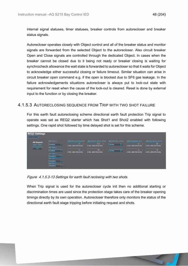
4.1.5.3 AUTORECLOSING SEQUENCE FROM TRIP WITH TWO SHOT FAILURE
For this earth fault autoreclosing scheme directional earth fault protection Trip signal to
operate was set as REQ2 starter which has Shot1 and Shot2 enabled with following
settings. One rapid shot followed by time delayed shot is set for this scheme.
Figure 4.1.5.3-13 Settings for earth fault reclosing with two shots.
When Trip signal is used for the autorecloser cycle init then no additional starting or
discrimination times are used since the protection stage takes care of the breaker opening
timings directly by its own operation. Autorecloser therefore only monitors the status of the
directional earth fault stage tripping before initiating request and shots.
Instruction manual –AQ S215 Bay Control IED 49 (204)
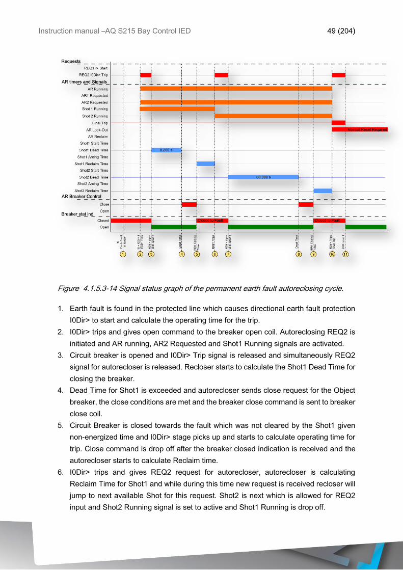
Figure 4.1.5.3-14 Signal status graph of the permanent earth fault autoreclosing cycle.
1. Earth fault is found in the protected line which causes directional earth fault protection
I0Dir> to start and calculate the operating time for the trip.
2. I0Dir> trips and gives open command to the breaker open coil. Autoreclosing REQ2 is
initiated and AR running, AR2 Requested and Shot1 Running signals are activated.
3. Circuit breaker is opened and I0Dir> Trip signal is released and simultaneously REQ2
signal for autorecloser is released. Recloser starts to calculate the Shot1 Dead Time for
closing the breaker.
4. Dead Time for Shot1 is exceeded and autorecloser sends close request for the Object
breaker, the close conditions are met and the breaker close command is sent to breaker
close coil.
5. Circuit Breaker is closed towards the fault which was not cleared by the Shot1 given
non-energized time and I0Dir> stage picks up and starts to calculate operating time for
trip. Close command is drop off after the breaker closed indication is received and the
autorecloser starts to calculate Reclaim time.
6. I0Dir> trips and gives REQ2 request for autorecloser, autorecloser is calculating
Reclaim Time for Shot1 and while during this time new request is received recloser will
jump to next available Shot for this request. Shot2 is next which is allowed for REQ2
input and Shot2 Running signal is set to active and Shot1 Running is drop off.
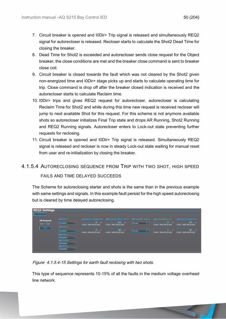
Instruction manual –AQ S215 Bay Control IED 50 (204)
7. Circuit breaker is opened and I0Dir> Trip signal is released and simultaneously REQ2
signal for autorecloser is released. Recloser starts to calculate the Shot2 Dead Time for
closing the breaker.
8. Dead Time for Shot2 is exceeded and autorecloser sends close request for the Object
breaker, the close conditions are met and the breaker close command is sent to breaker
close coil.
9. Circuit breaker is closed towards the fault which was not cleared by the Shot2 given
non-energized time and I0Dir> stage picks up and starts to calculate operating time for
trip. Close command is drop off after the breaker closed indication is received and the
autorecloser starts to calculate Reclaim time.
10. I0Dir> trips and gives REQ2 request for autorecloser, autorecloser is calculating
Reclaim Time for Shot2 and while during this time new request is received recloser will
jump to next available Shot for this request. For this scheme is not anymore available
shots so autorecloser initializes Final Trip state and drops AR Running, Shot2 Running
and REQ2 Running signals. Autorecloser enters to Lock-out state preventing further
requests for reclosing.
11. Circuit breaker is opened and I0Dir> Trip signal is released. Simultaneously REQ2
signal is released and recloser is now in steady Lock-out state waiting for manual reset
from user and re-initialization by closing the breaker.
4.1.5.4 AUTORECLOSING SEQUENCE FROM TRIP WITH TWO SHOT, HIGH SPEED
FAILS AND TIME DELAYED SUCCEEDS
The Scheme for autoreclosing starter and shots is the same than in the previous example
with same settings and signals. In this example fault persist for the high speed autoreclosing
but is cleared by time delayed autoreclosing.
Figure 4.1.5.4-15 Settings for earth fault reclosing with two shots.
This type of sequence represents 10-15% of all the faults in the medium voltage overhead
line network.
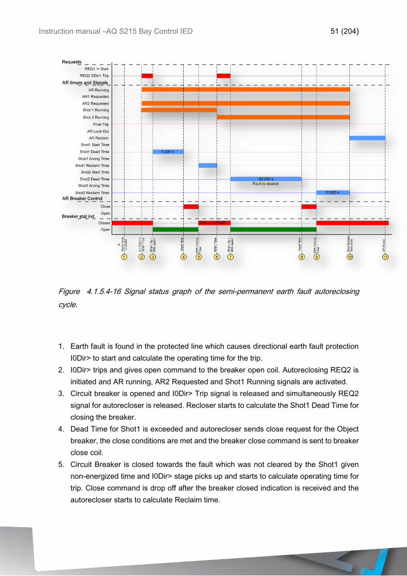
Instruction manual –AQ S215 Bay Control IED 51 (204)
Figure 4.1.5.4-16 Signal status graph of the semi-permanent earth fault autoreclosing
cycle.
1. Earth fault is found in the protected line which causes directional earth fault protection
I0Dir> to start and calculate the operating time for the trip.
2. I0Dir> trips and gives open command to the breaker open coil. Autoreclosing REQ2 is
initiated and AR running, AR2 Requested and Shot1 Running signals are activated.
3. Circuit breaker is opened and I0Dir> Trip signal is released and simultaneously REQ2
signal for autorecloser is released. Recloser starts to calculate the Shot1 Dead Time for
closing the breaker.
4. Dead Time for Shot1 is exceeded and autorecloser sends close request for the Object
breaker, the close conditions are met and the breaker close command is sent to breaker
close coil.
5. Circuit Breaker is closed towards the fault which was not cleared by the Shot1 given
non-energized time and I0Dir> stage picks up and starts to calculate operating time for
trip. Close command is drop off after the breaker closed indication is received and the
autorecloser starts to calculate Reclaim time.
Instruction manual –AQ S215 Bay Control IED 52 (204)
6. I0Dir> trips and gives REQ2 request for autorecloser, autorecloser is calculating
Reclaim Time for Shot1 and while during this time new request is received recloser will
jump to next available Shot for this request. Shot2 is next which is allowed for REQ2
input and Shot2 Running signal is set to active and Shot1 Running is drop off.
7. Circuit breaker is opened and I0Dir> Trip signal is released and simultaneously REQ2
signal for autorecloser is released. Recloser starts to calculate the Shot2 Dead Time for
closing the breaker.
8. Dead Time for Shot2 is exceeded and autorecloser sends close request for the Object
breaker, the close conditions are met and the breaker close command is sent to breaker
close coil.
9. Circuit breaker is closed and since fault cleared by the Shot2 given non-energized time
no pick-ups are detected Close command is drop off after the breaker closed indication
is received and the autorecloser starts to calculate Reclaim time for Shot2.
10. Reclaim Time for Shot2 is exceeded and the reclosing cycle is ended. AR running,
Shot2 Running and REQ2 Running signals are reset and Reclaim Time for the
Autorecloser application starts. Difference in between of the autoreclosing and shot
specific reclaim times is that if fault is returning in shot specific reclaim time autorecloser
jumps to next shot. If a fault return after successful cycle and Autoreclosing reclaim time
is running recloser will go directly to final trip state and lock-out state. This behavior can
be controlled with settings. Both of these reclaim times can be set to 0 when they are
not needed. Autoreclosing will skip all timers set to 0.
11. Autoreclosing Reclaim Time is exceeded and Autorecloser is set to Ready state waiting
for next request.
4.1.5.5 AUTORECLOSING SEQUENCE FROM TRIP WITH TWO SHOT, HIGH SPEED
SUCCEEDS
The Scheme for autoreclosing starter and shots is the same than in the previous examples
with same settings and signals. In this example fault is cleared by the high speed
autoreclosing.
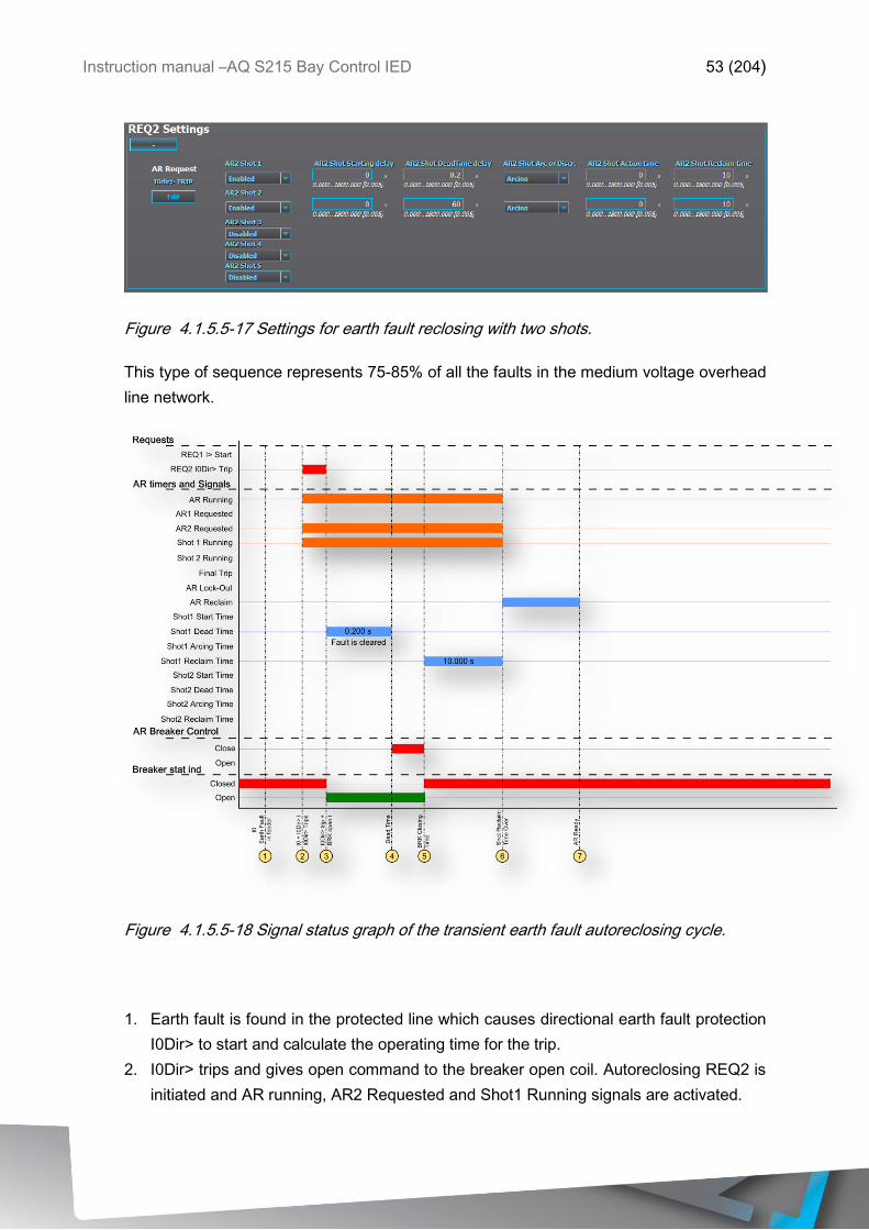
Instruction manual –AQ S215 Bay Control IED 53 (204)
Figure 4.1.5.5-17 Settings for earth fault reclosing with two shots.
This type of sequence represents 75-85% of all the faults in the medium voltage overhead
line network.
Figure 4.1.5.5-18 Signal status graph of the transient earth fault autoreclosing cycle.
1. Earth fault is found in the protected line which causes directional earth fault protection
I0Dir> to start and calculate the operating time for the trip.
2. I0Dir> trips and gives open command to the breaker open coil. Autoreclosing REQ2 is
initiated and AR running, AR2 Requested and Shot1 Running signals are activated.
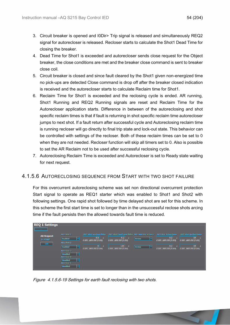
Instruction manual –AQ S215 Bay Control IED 54 (204)
3. Circuit breaker is opened and I0Dir> Trip signal is released and simultaneously REQ2
signal for autorecloser is released. Recloser starts to calculate the Shot1 Dead Time for
closing the breaker.
4. Dead Time for Shot1 is exceeded and autorecloser sends close request for the Object
breaker, the close conditions are met and the breaker close command is sent to breaker
close coil.
5. Circuit breaker is closed and since fault cleared by the Shot1 given non-energized time
no pick-ups are detected Close command is drop off after the breaker closed indication
is received and the autorecloser starts to calculate Reclaim time for Shot1.
6. Reclaim Time for Shot1 is exceeded and the reclosing cycle is ended. AR running,
Shot1 Running and REQ2 Running signals are reset and Reclaim Time for the
Autorecloser application starts. Difference in between of the autoreclosing and shot
specific reclaim times is that if fault is returning in shot specific reclaim time autorecloser
jumps to next shot. If a fault return after successful cycle and Autoreclosing reclaim time
is running recloser will go directly to final trip state and lock-out state. This behavior can
be controlled with settings of the recloser. Both of these reclaim times can be set to 0
when they are not needed. Recloser function will skip all timers set to 0. Also is possible
to set the AR Reclaim not to be used after successful reclosing cycle.
7. Autoreclosing Reclaim Time is exceeded and Autorecloser is set to Ready state waiting
for next request.
4.1.5.6 AUTORECLOSING SEQUENCE FROM START WITH TWO SHOT FAILURE
For this overcurrent autoreclosing scheme was set non directional overcurrent protection
Start signal to operate as REQ1 starter which was enabled to Shot1 and Shot2 with
following settings. One rapid shot followed by time delayed shot are set for this scheme. In
this scheme the first start time is set to longer than in the unsuccessful reclose shots arcing
time if the fault persists then the allowed towards fault time is reduced.
Figure 4.1.5.6-19 Settings for earth fault reclosing with two shots.
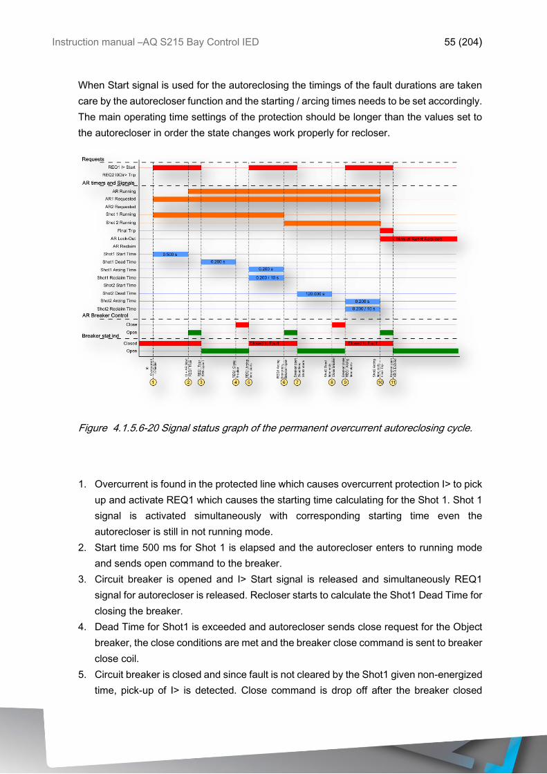
Instruction manual –AQ S215 Bay Control IED 55 (204)
When Start signal is used for the autoreclosing the timings of the fault durations are taken
care by the autorecloser function and the starting / arcing times needs to be set accordingly.
The main operating time settings of the protection should be longer than the values set to
the autorecloser in order the state changes work properly for recloser.
Figure 4.1.5.6-20 Signal status graph of the permanent overcurrent autoreclosing cycle.
1. Overcurrent is found in the protected line which causes overcurrent protection I> to pick
up and activate REQ1 which causes the starting time calculating for the Shot 1. Shot 1
signal is activated simultaneously with corresponding starting time even the
autorecloser is still in not running mode.
2. Start time 500 ms for Shot 1 is elapsed and the autorecloser enters to running mode
and sends open command to the breaker.
3. Circuit breaker is opened and I> Start signal is released and simultaneously REQ1
signal for autorecloser is released. Recloser starts to calculate the Shot1 Dead Time for
closing the breaker.
4. Dead Time for Shot1 is exceeded and autorecloser sends close request for the Object
breaker, the close conditions are met and the breaker close command is sent to breaker
close coil.
5. Circuit breaker is closed and since fault is not cleared by the Shot1 given non-energized
time, pick-up of I> is detected. Close command is drop off after the breaker closed
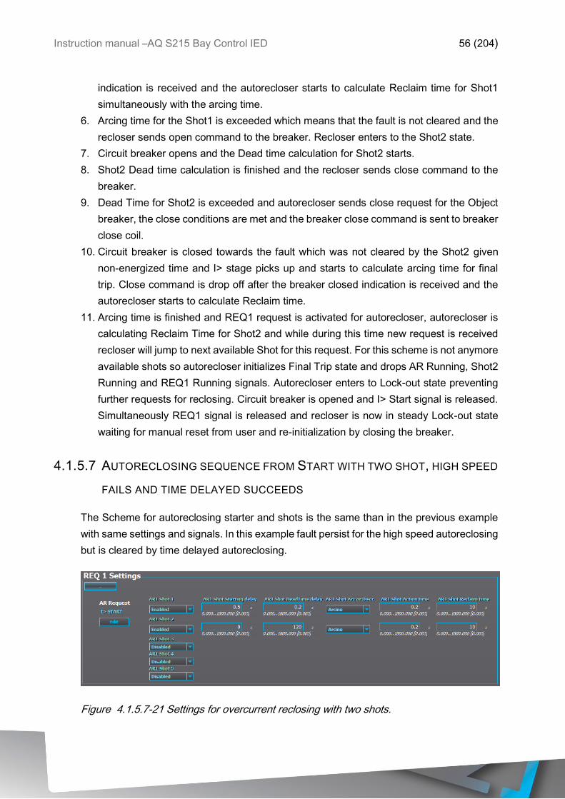
Instruction manual –AQ S215 Bay Control IED 56 (204)
indication is received and the autorecloser starts to calculate Reclaim time for Shot1
simultaneously with the arcing time.
6. Arcing time for the Shot1 is exceeded which means that the fault is not cleared and the
recloser sends open command to the breaker. Recloser enters to the Shot2 state.
7. Circuit breaker opens and the Dead time calculation for Shot2 starts.
8. Shot2 Dead time calculation is finished and the recloser sends close command to the
breaker.
9. Dead Time for Shot2 is exceeded and autorecloser sends close request for the Object
breaker, the close conditions are met and the breaker close command is sent to breaker
close coil.
10. Circuit breaker is closed towards the fault which was not cleared by the Shot2 given
non-energized time and I> stage picks up and starts to calculate arcing time for final
trip. Close command is drop off after the breaker closed indication is received and the
autorecloser starts to calculate Reclaim time.
11. Arcing time is finished and REQ1 request is activated for autorecloser, autorecloser is
calculating Reclaim Time for Shot2 and while during this time new request is received
recloser will jump to next available Shot for this request. For this scheme is not anymore
available shots so autorecloser initializes Final Trip state and drops AR Running, Shot2
Running and REQ1 Running signals. Autorecloser enters to Lock-out state preventing
further requests for reclosing. Circuit breaker is opened and I> Start signal is released.
Simultaneously REQ1 signal is released and recloser is now in steady Lock-out state
waiting for manual reset from user and re-initialization by closing the breaker.
4.1.5.7 AUTORECLOSING SEQUENCE FROM START WITH TWO SHOT, HIGH SPEED
FAILS AND TIME DELAYED SUCCEEDS
The Scheme for autoreclosing starter and shots is the same than in the previous example
with same settings and signals. In this example fault persist for the high speed autoreclosing
but is cleared by time delayed autoreclosing.
Figure 4.1.5.7-21 Settings for overcurrent reclosing with two shots.
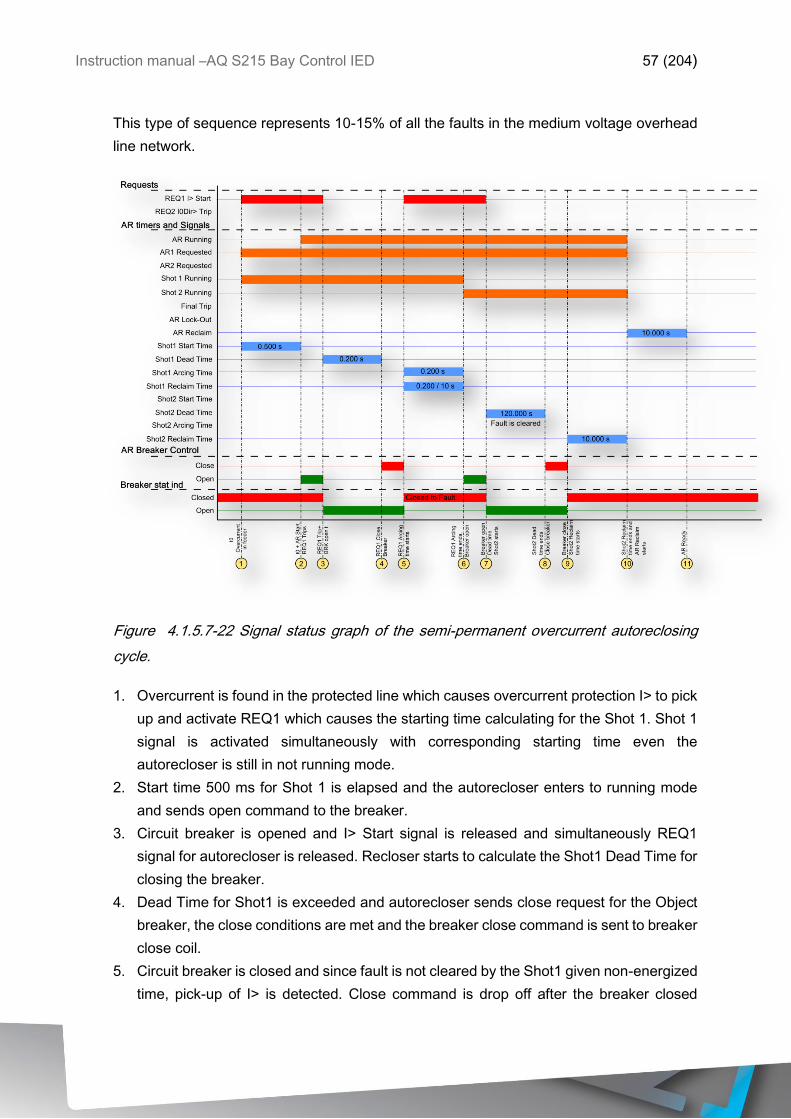
Instruction manual –AQ S215 Bay Control IED 57 (204)
This type of sequence represents 10-15% of all the faults in the medium voltage overhead
line network.
Figure 4.1.5.7-22 Signal status graph of the semi-permanent overcurrent autoreclosing
cycle.
1. Overcurrent is found in the protected line which causes overcurrent protection I> to pick
up and activate REQ1 which causes the starting time calculating for the Shot 1. Shot 1
signal is activated simultaneously with corresponding starting time even the
autorecloser is still in not running mode.
2. Start time 500 ms for Shot 1 is elapsed and the autorecloser enters to running mode
and sends open command to the breaker.
3. Circuit breaker is opened and I> Start signal is released and simultaneously REQ1
signal for autorecloser is released. Recloser starts to calculate the Shot1 Dead Time for
closing the breaker.
4. Dead Time for Shot1 is exceeded and autorecloser sends close request for the Object
breaker, the close conditions are met and the breaker close command is sent to breaker
close coil.
5. Circuit breaker is closed and since fault is not cleared by the Shot1 given non-energized
time, pick-up of I> is detected. Close command is drop off after the breaker closed
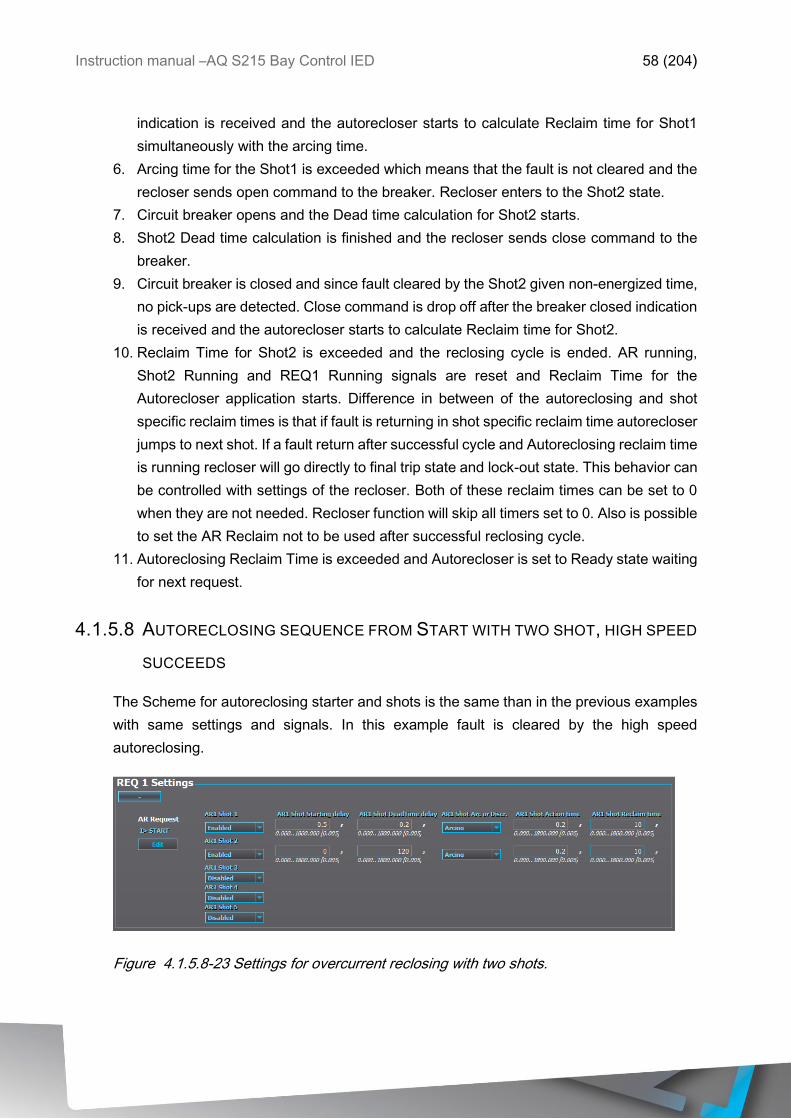
Instruction manual –AQ S215 Bay Control IED 58 (204)
indication is received and the autorecloser starts to calculate Reclaim time for Shot1
simultaneously with the arcing time.
6. Arcing time for the Shot1 is exceeded which means that the fault is not cleared and the
recloser sends open command to the breaker. Recloser enters to the Shot2 state.
7. Circuit breaker opens and the Dead time calculation for Shot2 starts.
8. Shot2 Dead time calculation is finished and the recloser sends close command to the
breaker.
9. Circuit breaker is closed and since fault cleared by the Shot2 given non-energized time,
no pick-ups are detected. Close command is drop off after the breaker closed indication
is received and the autorecloser starts to calculate Reclaim time for Shot2.
10. Reclaim Time for Shot2 is exceeded and the reclosing cycle is ended. AR running,
Shot2 Running and REQ1 Running signals are reset and Reclaim Time for the
Autorecloser application starts. Difference in between of the autoreclosing and shot
specific reclaim times is that if fault is returning in shot specific reclaim time autorecloser
jumps to next shot. If a fault return after successful cycle and Autoreclosing reclaim time
is running recloser will go directly to final trip state and lock-out state. This behavior can
be controlled with settings of the recloser. Both of these reclaim times can be set to 0
when they are not needed. Recloser function will skip all timers set to 0. Also is possible
to set the AR Reclaim not to be used after successful reclosing cycle.
11. Autoreclosing Reclaim Time is exceeded and Autorecloser is set to Ready state waiting
for next request.
4.1.5.8 AUTORECLOSING SEQUENCE FROM START WITH TWO SHOT, HIGH SPEED
SUCCEEDS
The Scheme for autoreclosing starter and shots is the same than in the previous examples
with same settings and signals. In this example fault is cleared by the high speed
autoreclosing.
Figure 4.1.5.8-23 Settings for overcurrent reclosing with two shots.
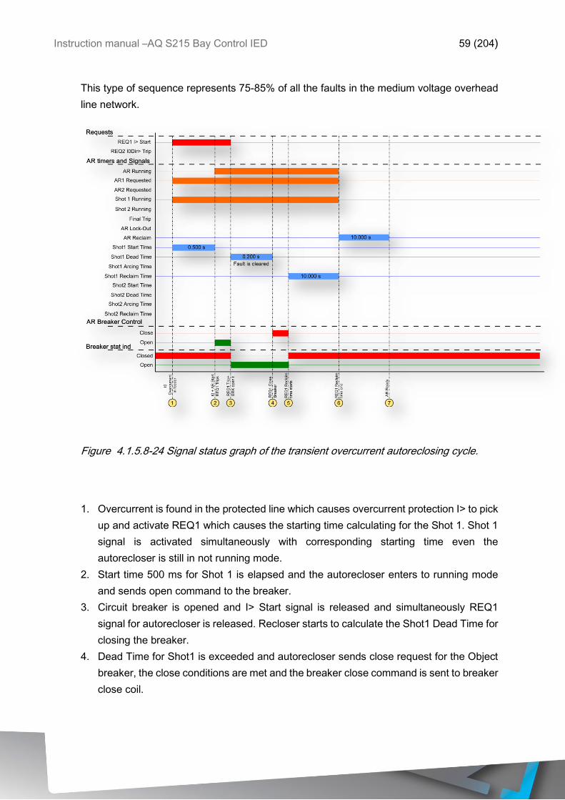
Instruction manual –AQ S215 Bay Control IED 59 (204)
This type of sequence represents 75-85% of all the faults in the medium voltage overhead
line network.
Figure 4.1.5.8-24 Signal status graph of the transient overcurrent autoreclosing cycle.
1. Overcurrent is found in the protected line which causes overcurrent protection I> to pick
up and activate REQ1 which causes the starting time calculating for the Shot 1. Shot 1
signal is activated simultaneously with corresponding starting time even the
autorecloser is still in not running mode.
2. Start time 500 ms for Shot 1 is elapsed and the autorecloser enters to running mode
and sends open command to the breaker.
3. Circuit breaker is opened and I> Start signal is released and simultaneously REQ1
signal for autorecloser is released. Recloser starts to calculate the Shot1 Dead Time for
closing the breaker.
4. Dead Time for Shot1 is exceeded and autorecloser sends close request for the Object
breaker, the close conditions are met and the breaker close command is sent to breaker
close coil.
Instruction manual –AQ S215 Bay Control IED 60 (204)
5. Circuit breaker is closed and since fault cleared by the Shot1 given non-energized time,
no pick-ups are detected. Close command is drop off after the breaker closed indication
is received and the autorecloser starts to calculate Reclaim time for Shot1.
6. Reclaim Time for Shot1 is exceeded and the reclosing cycle is ended. AR running,
Shot1 Running and REQ1 Running signals are reset and Reclaim Time for the
Autorecloser application starts. Difference in between of the autoreclosing and shot
specific reclaim times is that if fault is returning in shot specific reclaim time autorecloser
jumps to next shot. If a fault return after successful cycle and Autoreclosing reclaim time
is running recloser will go directly to final trip state and lock-out state. This behavior can
be controlled with settings of the recloser. Both of these reclaim times can be set to 0
when they are not needed. Recloser function will skip all timers set to 0. Also is possible
to set the AR Reclaim not to be used after successful reclosing cycle.
7. Autoreclosing Reclaim Time is exceeded and Autorecloser is set to Ready state waiting
for next request.
4.1.5.9 AUTORECLOSING IN MESHED OR RING NETWORKS
If the overhead line feeder has distributed power generation, which can arise even more
often in the future since renewable power sources become more common, typical
autoreclosing scheme cannot be applied directly. In this kind of autoreclosing schemes two
end autoreclosing has to be used so that the relays in both ends of the line operate as
master-follower autoreclosing in co-operation. If the reclosing is not applied so that the DG
power plant is disconnected prior to the breaker close command, firstly the reclosing will fail
since the DG power plant will keep the fault on during the dead time of the autorecloser and
also the closing of the breaker when the main grid has been disconnected from the DG
power plant will most probably cause problems for the DG power plant due to phase shift
of the DG power plant during the dead time.
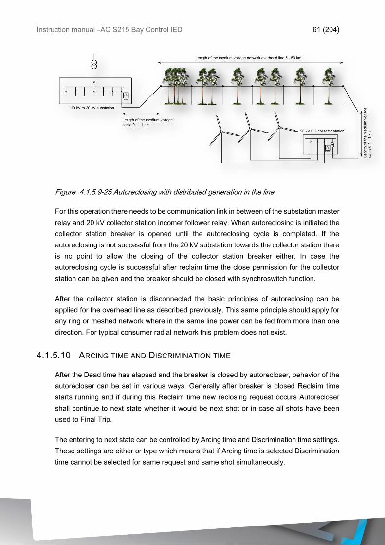
Instruction manual –AQ S215 Bay Control IED 61 (204)
Figure 4.1.5.9-25 Autoreclosing with distributed generation in the line.
For this operation there needs to be communication link in between of the substation master
relay and 20 kV collector station incomer follower relay. When autoreclosing is initiated the
collector station breaker is opened until the autoreclosing cycle is completed. If the
autoreclosing is not successful from the 20 kV substation towards the collector station there
is no point to allow the closing of the collector station breaker either. In case the
autoreclosing cycle is successful after reclaim time the close permission for the collector
station can be given and the breaker should be closed with synchroswitch function.
After the collector station is disconnected the basic principles of autoreclosing can be
applied for the overhead line as described previously. This same principle should apply for
any ring or meshed network where in the same line power can be fed from more than one
direction. For typical consumer radial network this problem does not exist.
4.1.5.10 ARCING TIME AND DISCRIMINATION TIME
After the Dead time has elapsed and the breaker is closed by autorecloser, behavior of the
autorecloser can be set in various ways. Generally after breaker is closed Reclaim time
starts running and if during this Reclaim time new reclosing request occurs Autorecloser
shall continue to next state whether it would be next shot or in case all shots have been
used to Final Trip.
The entering to next state can be controlled by Arcing time and Discrimination time settings.
These settings are either or type which means that if Arcing time is selected Discrimination
time cannot be selected for same request and same shot simultaneously.
Instruction manual –AQ S215 Bay Control IED 62 (204)
Arcing time can be used for controlling the autoreclosing in cases protection function Start
signal is making the requests. In case if the request (start) activates during the Reclaim time
the Arcing time calculation starts and if fault persists autorecloser shall continue to next
stage. If Arcing time calculation starts but stops before the set time have been used then
Reclaim time calculation continues normally and when it is elapsed autorecloser shall return
to either General Reclaim time or into Ready mode and the shot is considered as
successful. Arcing time counter is not resetting from the request drop off during the Reclaim
time and every time the request is activated (e.g. protection function starts) the arcing time
counter is deducted by the time request is on. This means that the time set to Arcing time
parameter means cumulative time of start allowed in Reclaim time before decision is made
that the shot is failed or succeeded.
In case the autoreclosing is used in the time coordinated network protected by IDMT time
characteristics and the relays are old mechanical types which have also current dependent
release time the operation of the protection selectivity has to be guaranteed by allowing all
of the relays timing devices reset completely during the dead time so that the correct time
discrimination is maintained after reclosing to the fault. Time required for mechanical IDMT
relay to reset may be even 10 s in some cases. When short dead times are required the
relays should reset almost instantaneously so that the current dependent time grading
operates as expected. For these cases in the autorecloser is possible to set certain
discrimination time instead of arcing time, which starts simultaneously with reclaim time and
if during this discrimination time any new reclosing requests are made the recloser will halt
and let the protection devices operate based into their settings and does not interfere on
the operation of the protection functions or the breaker. This means also that further
reclosing are not made before the autorecloser is reset manually and the breaker shall
remain open until it is manually closed.
4.1.5.11 AUTORECLOSER IO
Main outputs of the autorecloser function are Object open and Object close control signals.
In addition to these output controls the function will report the recloser status information to
be used in the logics or LED indications as well as applied operations. Setting parameters
are static inputs for the function which are changed only by user input in the setup phase of
the function.
Inputs for the function are binary recloser request signals, blockings and controlling signals,
controlled object monitoring and status signals. The function registers its operation into 12
last time-stamped registers and also generates general time stamped ON/OFF events to
the common event buffer from each of the two output signal as well as several operational
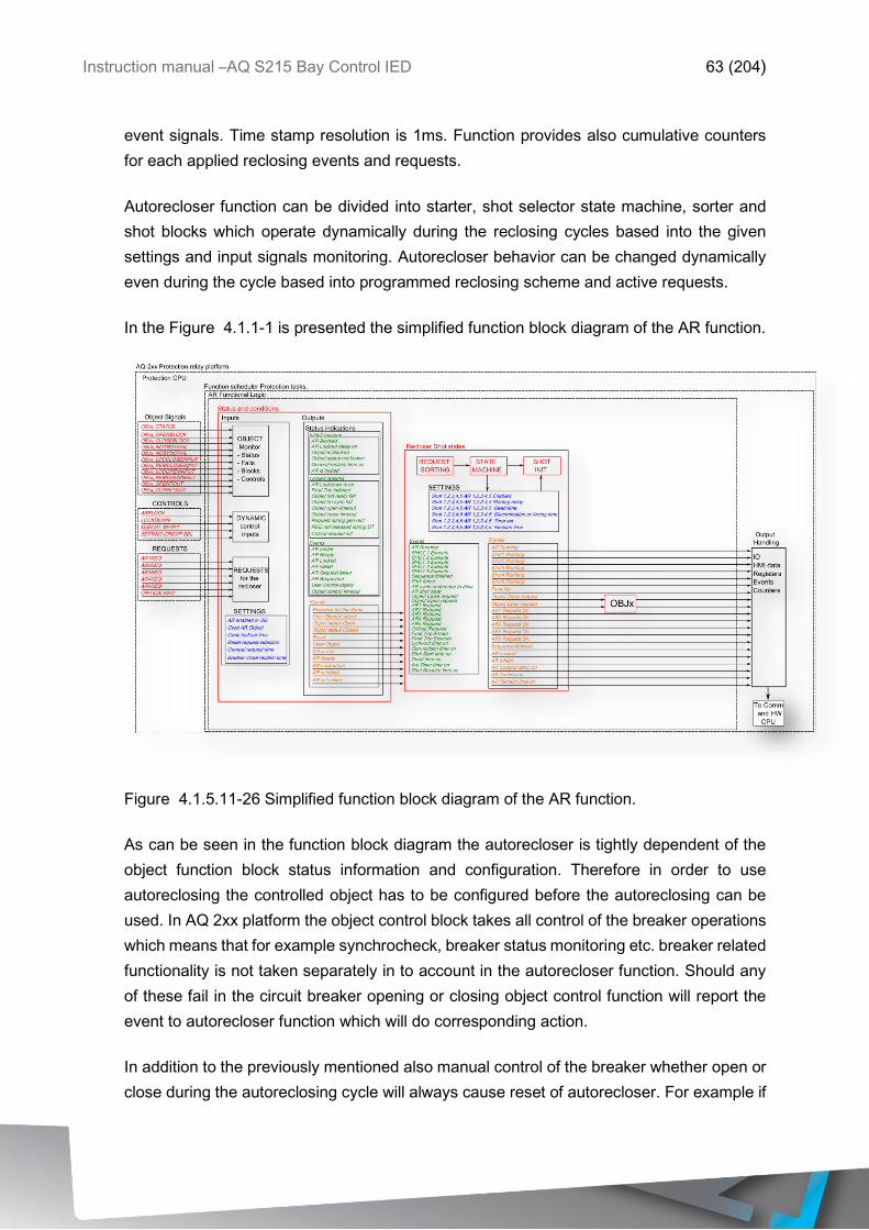
Instruction manual –AQ S215 Bay Control IED 63 (204)
event signals. Time stamp resolution is 1ms. Function provides also cumulative counters
for each applied reclosing events and requests.
Autorecloser function can be divided into starter, shot selector state machine, sorter and
shot blocks which operate dynamically during the reclosing cycles based into the given
settings and input signals monitoring. Autorecloser behavior can be changed dynamically
even during the cycle based into programmed reclosing scheme and active requests.
In the Figure 4.1.1-1 is presented the simplified function block diagram of the AR function.
Figure 4.1.5.11-26 Simplified function block diagram of the AR function.
As can be seen in the function block diagram the autorecloser is tightly dependent of the
object function block status information and configuration. Therefore in order to use
autoreclosing the controlled object has to be configured before the autoreclosing can be
used. In AQ 2xx platform the object control block takes all control of the breaker operations
which means that for example synchrocheck, breaker status monitoring etc. breaker related
functionality is not taken separately in to account in the autorecloser function. Should any
of these fail in the circuit breaker opening or closing object control function will report the
event to autorecloser function which will do corresponding action.
In addition to the previously mentioned also manual control of the breaker whether open or
close during the autoreclosing cycle will always cause reset of autorecloser. For example if
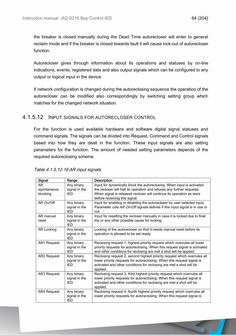
Instruction manual –AQ S215 Bay Control IED 64 (204)
the breaker is closed manually during the Dead Time autorecloser will enter to general
reclaim mode and if the breaker is closed towards fault it will cause lock-out of autorecloser
function.
Autorecloser gives through information about its operations and statuses by on-line
indications, events, registered data and also output signals which can be configured to any
output or logical input in the device.
If network configuration is changed during the autoreclosing sequence the operation of the
autorecloser can be modified also correspondingly by switching setting group which
matches for the changed network situation.
4.1.5.12 INPUT SIGNALS FOR AUTORECLOSER CONTROL
For the function is used available hardware and software digital signal statuses and
command signals. The signals can be divided into Request, Command and Control signals
based into how they are dealt in the function. These input signals are also setting
parameters for the function. The amount of needed setting parameters depends of the
required autoreclosing scheme.
Table 4.1.5.12-16 AR input signals.
Signal Range Description
AR
spontaneous
blocking
Any binary
signal in the
IED
Input for dynamically block the autoreclosing. When input is activated
the recloser will halt its operation and refuses any further requests.
When signal is released recloser will continue its operation as were
before receiving this signal.
AR On/Off Any binary
signal in the
IED
Input for enabling or disabling the autorecloser by user selected input.
Parameter Use AR On/Off signals defines if this input signal is in use or
not.
AR manual
reset
Any binary
signal in the
IED
Input for resetting the recloser manually in case it is locked due to final
trip or any other possible cause for locking.
AR Locking Any binary
signal in the
IED
Locking of the autorecloser so that it needs manual reset before its
operation is allowed to be set ready.
AR1 Request Any binary
signal in the
IED
Reclosing request 1, highest priority request which overrules all lower
priority requests for autoreclosing. When this request signal is activated
and other conditions for reclosing are met a shot will be applied.
AR2 Request Any binary
signal in the
IED
Reclosing request 2, second highest priority request which overrules all
lower priority requests for autoreclosing. When this request signal is
activated and other conditions for reclosing are met a shot will be
applied.
AR3 Request Any binary
signal in the
IED
Reclosing request 3, third highest priority request which overrules all
lower priority requests for autoreclosing. When this request signal is
activated and other conditions for reclosing are met a shot will be
applied.
AR4 Request Any binary
signal in the
IED
Reclosing request 4, fourth highest priority request which overrules all
lower priority requests for autoreclosing. When this request signal is
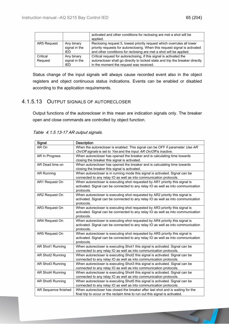
Instruction manual –AQ S215 Bay Control IED 65 (204)
activated and other conditions for reclosing are met a shot will be
applied.
AR5 Request Any binary
signal in the
IED
Reclosing request 5, lowest priority request which overrules all lower
priority requests for autoreclosing. When this request signal is activated
and other conditions for reclosing are met a shot will be applied.
Critical
Request
Any binary
signal in the
IED
Critical request for autoreclosing, if this signal is activated the
autorecloser shall go directly to locked state and trip the breaker directly
in the moment the request was received.
Status change of the input signals will always cause recorded event also in the object
registers and object continuous status indications. Events can be enabled or disabled
according to the application requirements.
4.1.5.13 OUTPUT SIGNALS OF AUTORECLOSER
Output functions of the autorecloser in this mean are indication signals only. The breaker
open and close commands are controlled by object function.
Table 4.1.5.13-17 AR output signals.
Signal Description
AR On When the autorecloser is enabled. This signal can be OFF if parameter Use AR On/Off signals is set to Yes and the input AR On/Off is inactive.
AR In Progress When autorecloser has opened the breaker and is calculating time towards
closing the breaker this signal is activated.
AR Dead time on When autorecloser has opened the breaker and is calculating time towards
closing the breaker this signal is activated.
AR Running When autorecloser is in running mode this signal is activated. Signal can be
connected to any relay IO as well as into communication protocols.
AR1 Request On When autorecloser is executing shot requested by AR1 priority this signal is
activated. Signal can be connected to any relay IO as well as into communication
protocols.
AR2 Request On When autorecloser is executing shot requested by AR2 priority this signal is
activated. Signal can be connected to any relay IO as well as into communication
protocols.
AR3 Request On When autorecloser is executing shot requested by AR3 priority this signal is
activated. Signal can be connected to any relay IO as well as into communication
protocols.
AR4 Request On When autorecloser is executing shot requested by AR4 priority this signal is
activated. Signal can be connected to any relay IO as well as into communication
protocols.
AR5 Request On When autorecloser is executing shot requested by AR5 priority this signal is
activated. Signal can be connected to any relay IO as well as into communication
protocols.
AR Shot1 Running When autorecloser is executing Shot1 this signal is activated. Signal can be
connected to any relay IO as well as into communication protocols.
AR Shot2 Running When autorecloser is executing Shot2 this signal is activated. Signal can be
connected to any relay IO as well as into communication protocols.
AR Shot3 Running When autorecloser is executing Shot3 this signal is activated. Signal can be
connected to any relay IO as well as into communication protocols.
AR Shot4 Running When autorecloser is executing Shot4 this signal is activated. Signal can be
connected to any relay IO as well as into communication protocols.
AR Shot5 Running When autorecloser is executing Shot5 this signal is activated. Signal can be
connected to any relay IO as well as into communication protocols.
AR Sequence finished When autorecloser has closed the breaker after last shot and is waiting for the
final trip to occur or the reclaim time to run out this signal is activated.

Instruction manual –AQ S215 Bay Control IED 66 (204)
Final Trip When autorecloser has executed Final Trip command this signal is activated.
Signal can be connected to any relay IO as well as into communication protocols.
AR Locked When autorecloser is in Locked mode this signal is activated. Signal can be
connected to any relay IO as well as into communication protocols.
AR Operation inhibit When autorecloser is in Inhibit mode this signal is activated. Signal can be
connected to any relay IO as well as into communication protocols.
AR Lockout delay On When autorecloser is calculating Lockout delay this signal is activated. Signal can
be connected to any relay IO as well as into communication protocols.
AR Arcing time On When autorecloser is calculating Arcing time this signal is activated. Signal can be
connected to any relay IO as well as into communication protocols.
AR Reclaim time On When autorecloser is calculating Reclaim time this signal is activated. Signal can
be connected to any relay IO as well as into communication protocols.
AR Ready When autorecloser is ready to execute the reclosing sequence in case a fault is
detected this signal is active.
AR Lockout after
successful sequence
When autorecloser sequence has been successful but new fault was detected
before lockout time has been depleted no new sequence will be started and this
signal will be activated. Instead AR will go into locked mode.
Status change of the output signals will always cause recorded event also in the AR
registers and AR continuous status indications. Events can be enabled or disabled
according to the application requirements.
4.1.5.14 SETTING PARAMETERS
Autorecloser function has freely configurable settings for all areas of the function in order to
control the operation of the autoreclosing application to suit different kind of needs.
Operation of the autorecloser can be static or dynamic based into if setting groups are used.
In autorecloser are found basic settings and shot related settings. Basic settings control the
desired Object selection as well as general behavior of the autorecloser in different
operating schemes.
Table 4.1.5.14-18 Autorecloser basic settings.
Setting Range SG Description
AR Mode 0: Disabled
1: Enabled
No Selection of the Autorecloser Enabled / Disabled in
the configuration. Default value is Disabled.
AR Object 0: Object 1
1: Object 2
2: Object 3
3: Object 4
4: Object 5
8 Selection of the monitored / controlled breaker object.
This selection defines the Object the autorecloser
monitoring and control signals are issued. This
selection can be changed dynamically by setting
group selection in real time in the IED. Default setting
is Object 1.
AR Enabled in SG 0: Disabled
1: Enabled
8 Selection of the autoreclosing activation in current
setting group. It is possible to disable / enable
autoreclosing in each setting group independently.
This selection can be changed dynamically by setting
group selection in real time in the IED. Default setting
is Disabled.
Manual resetting 0: Required
1: Obj Close resets
8 Selection of the autorecloser resetting after locking
(final trip, error condition), can be set so that only
manual reset to resetting input of the function resets
autorecloser or general breaker close command from
any source resets the autorecloser. This selection
can be changed dynamically by setting group
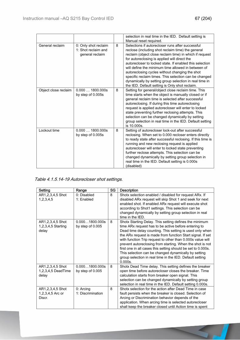
Instruction manual –AQ S215 Bay Control IED 67 (204)
selection in real time in the IED. Default setting is
Manual reset required.
General reclaim 0: Only shot reclaim
1: Shot reclaim and
general reclaim
8 Selections if autorecloser runs after successful
reclose (including shot reclaim time) the general
reclaim (object close reclaim time) in which if request
for autoreclosing is applied will direct the
autorecloser to locked state. If enabled this selection
will define the minimum time allowed in between of
autoreclosing cycles without changing the shot
specific reclaim times. This selection can be changed
dynamically by setting group selection in real time in
the IED. Default setting is Only shot reclaim.
Object close reclaim 0.000 … 1800.000s
by step of 0.005s
8 Setting for general/object close reclaim time. This
time starts when the object is manually closed or if
general reclaim time is selected after successful
autoreclosing. If during this time autoreclosing
request is applied autorecloser will enter to locked
state preventing further reclosing attempts. This
selection can be changed dynamically by setting
group selection in real time in the IED. Default setting
is 10.000s.
Lockout time 0.000 … 1800.000s
by step of 0.005s
8 Setting of autorecloser lock-out after successful
reclosing. When set to 0.000 recloser enters directly
to ready state after successful reclosing. If this time is
running and new reclosing request is applied
autorecloser will enter to locked state preventing
further reclose attempts. This selection can be
changed dynamically by setting group selection in
real time in the IED. Default setting is 0.000s
(disabled)
Table 4.1.5.14-19 Autorecloser shot settings.
Setting Range SG Description
AR1,2,3,4,5 Shot
1,2,3,4,5
0: Disabled
1: Enabled
8 Shotx selection enabled / disabled for request ARx. If
disabled ARx request will skip Shot 1 and seek for next
enabled shot. If enabled ARx request will execute shot
according to Shot1 settings. This selection can be
changed dynamically by setting group selection in real
time in the IED.
AR1,2,3,4,5 Shot
1,2,3,4,5 Starting
delay
0.000…1800.000s
by step of 0.005
8 Shotx Starting Delay. This setting defines the minimum
time ARx request has to be active before entering to
Dead time delay counting. This setting is used only when
the ARx request is made from function Start signal. If set
with function Trip request to other than 0.000s value will
prevent autoreclosing from starting. When the shot is not
first one in all cases this setting should be set to 0.000s.
This selection can be changed dynamically by setting
group selection in real time in the IED. Default setting
0.000s.
AR1,2,3,4,5 Shot
1,2,3,4,5 DeadTime
delay
0.000…1800.000s
by step of 0.005
8 Shotx Dead Time delay. This setting defines the breaker
open time before autorecloser closes the breaker. Time
calculation starts from breaker open signal. This
selection can be changed dynamically by setting group
selection in real time in the IED. Default setting 0.000s.
AR1,2,3,4,5 Shot
1,2,3,4,5 Arc or
Discr.
0: Arcing
1: Discrimination
8 Shotx selection for the action after Dead Time in case
fault persists when the breaker is closed. Selection of
Arcing or Discrimination behavior depends of the
application. When arcing time is selected autorecloser
shall keep the breaker closed until Action time is spent
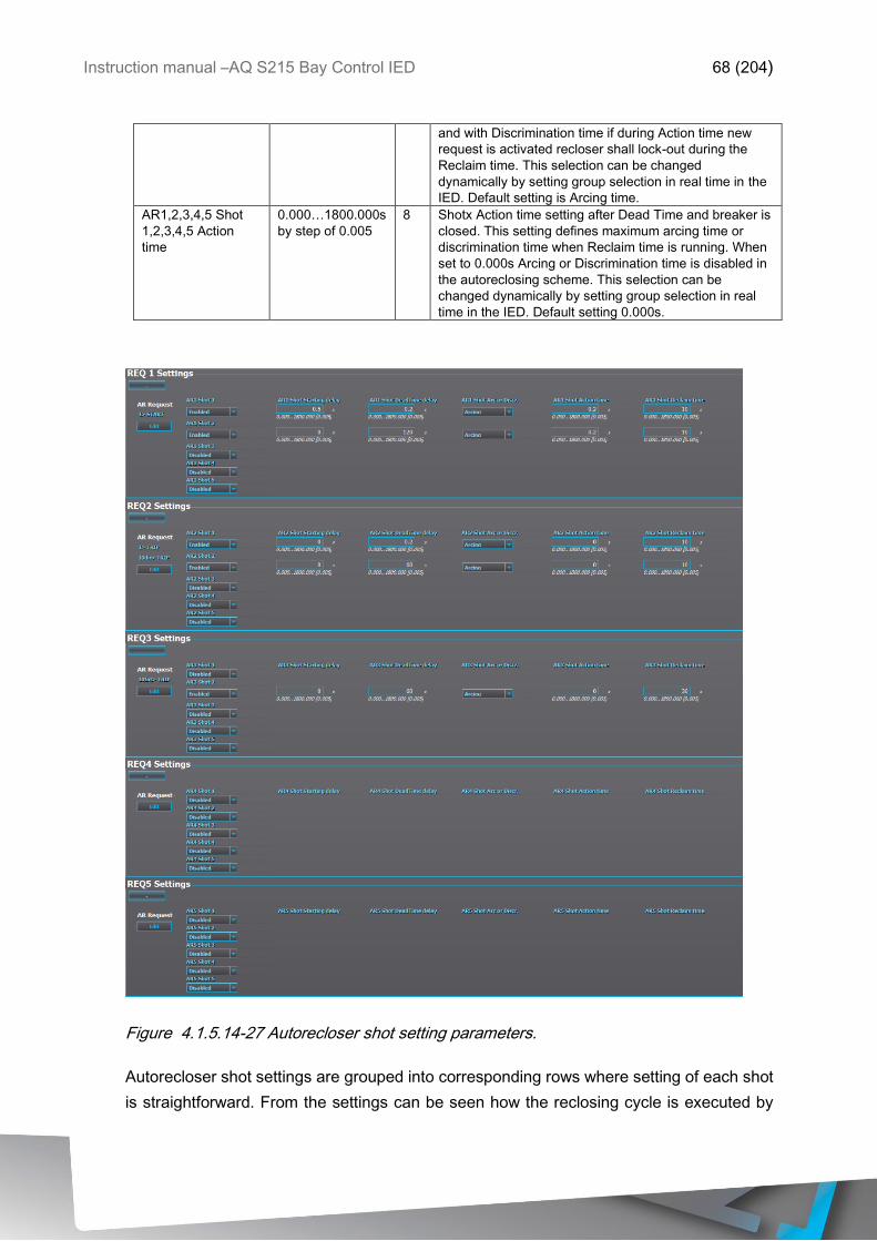
Instruction manual –AQ S215 Bay Control IED 68 (204)
and with Discrimination time if during Action time new
request is activated recloser shall lock-out during the
Reclaim time. This selection can be changed
dynamically by setting group selection in real time in the
IED. Default setting is Arcing time.
AR1,2,3,4,5 Shot
1,2,3,4,5 Action
time
0.000…1800.000s
by step of 0.005
8 Shotx Action time setting after Dead Time and breaker is
closed. This setting defines maximum arcing time or
discrimination time when Reclaim time is running. When
set to 0.000s Arcing or Discrimination time is disabled in
the autoreclosing scheme. This selection can be
changed dynamically by setting group selection in real
time in the IED. Default setting 0.000s.
Figure 4.1.5.14-27 Autorecloser shot setting parameters.
Autorecloser shot settings are grouped into corresponding rows where setting of each shot
is straightforward. From the settings can be seen how the reclosing cycle is executed by
Instruction manual –AQ S215 Bay Control IED 69 (204)
each request row by row and which functions initiate requests and which shots and requests
are in use.
This setting example presents two shot autoreclosing. For example of the reading of the
settings AR1 request is started by I> Start signal and AR2 is started by I0Dir> Trip signal.
Timings for AR1 is 500ms starting time followed by 200ms Dead time which after 200ms
Arcing time and 10s Reclaim time for Shot 1. If Shot 1 fails follows 120s dead time, 200ms
Arcing time and 10s Reclaim time. If Shot 2 fails recloser shall init Final Trip. For AR2
request the reading of the settings is exactly the same, the values can be read from 2nd row.
3rd request has just one shot with 60 second dead time. If AR4 or 5 requests are activated,
from the corresponding rows from left to right and from up to down can be seen the
autoreclosing schemes for each request.
4.1.5.15 INHIBIT AND LOCKED STATES OF AUTORECLOSER FUNCTION
Autorecloser can have several reasons to go into locked and inhibit states where reclosing
for some given reason cannot be allowed. When autorecloser function enters the not ready
state it will give indication of the reason it cannot be in ready state in order to quickly rectify
what is causing the problem of the functions operation. Reason is indicated in the
autorecloser registers-menu.
Inhibit reasons for autorecloser are following:
o AR is blocked (from Blocking input)
o AR is not enabled
o AR is calculating lock-out delay
o Object open or close is blocked
o Object status is not known
o General reclaim time is running
o AR is locked
When AR is in inhibit state it will recover to ready state when the reason for the inhibition is
removed.
Lock-out reasons for autorecloser are following:
o Lock down signal is init (from Lockdown input)
o Final Trip signal is given
o Object not ready failed in given time (from Object)
o Object no sync failed in given time (from Object)
o Object open timeout (from Object)
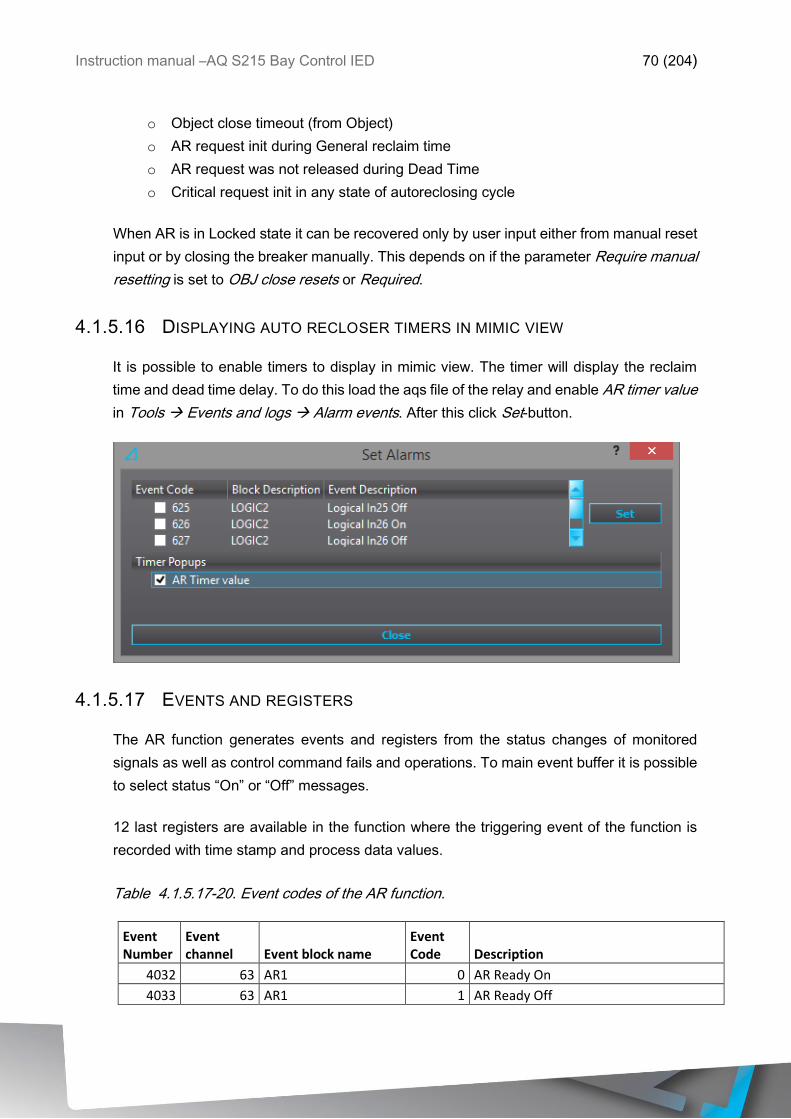
Instruction manual –AQ S215 Bay Control IED 70 (204)
o Object close timeout (from Object)
o AR request init during General reclaim time
o AR request was not released during Dead Time
o Critical request init in any state of autoreclosing cycle
When AR is in Locked state it can be recovered only by user input either from manual reset
input or by closing the breaker manually. This depends on if the parameter Require manual
resetting is set to OBJ close resets or Required.
4.1.5.16 DISPLAYING AUTO RECLOSER TIMERS IN MIMIC VIEW
It is possible to enable timers to display in mimic view. The timer will display the reclaim
time and dead time delay. To do this load the aqs file of the relay and enable AR timer value
in Tools Events and logs Alarm events. After this click Set-button.
4.1.5.17 EVENTS AND REGISTERS
The AR function generates events and registers from the status changes of monitored
signals as well as control command fails and operations. To main event buffer it is possible
to select status “On” or “Off” messages.
12 last registers are available in the function where the triggering event of the function is
recorded with time stamp and process data values.
Table 4.1.5.17-20. Event codes of the AR function.
Event Number
Event channel Event block name
Event Code Description
4032 63 AR1 0 AR Ready On
4033 63 AR1 1 AR Ready Off
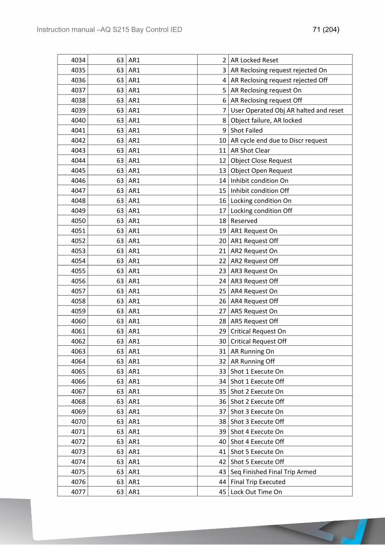
Instruction manual –AQ S215 Bay Control IED 71 (204)
4034 63 AR1 2 AR Locked Reset
4035 63 AR1 3 AR Reclosing request rejected On
4036 63 AR1 4 AR Reclosing request rejected Off
4037 63 AR1 5 AR Reclosing request On
4038 63 AR1 6 AR Reclosing request Off
4039 63 AR1 7 User Operated Obj AR halted and reset
4040 63 AR1 8 Object failure, AR locked
4041 63 AR1 9 Shot Failed
4042 63 AR1 10 AR cycle end due to Discr request
4043 63 AR1 11 AR Shot Clear
4044 63 AR1 12 Object Close Request
4045 63 AR1 13 Object Open Request
4046 63 AR1 14 Inhibit condition On
4047 63 AR1 15 Inhibit condition Off
4048 63 AR1 16 Locking condition On
4049 63 AR1 17 Locking condition Off
4050 63 AR1 18 Reserved
4051 63 AR1 19 AR1 Request On
4052 63 AR1 20 AR1 Request Off
4053 63 AR1 21 AR2 Request On
4054 63 AR1 22 AR2 Request Off
4055 63 AR1 23 AR3 Request On
4056 63 AR1 24 AR3 Request Off
4057 63 AR1 25 AR4 Request On
4058 63 AR1 26 AR4 Request Off
4059 63 AR1 27 AR5 Request On
4060 63 AR1 28 AR5 Request Off
4061 63 AR1 29 Critical Request On
4062 63 AR1 30 Critical Request Off
4063 63 AR1 31 AR Running On
4064 63 AR1 32 AR Running Off
4065 63 AR1 33 Shot 1 Execute On
4066 63 AR1 34 Shot 1 Execute Off
4067 63 AR1 35 Shot 2 Execute On
4068 63 AR1 36 Shot 2 Execute Off
4069 63 AR1 37 Shot 3 Execute On
4070 63 AR1 38 Shot 3 Execute Off
4071 63 AR1 39 Shot 4 Execute On
4072 63 AR1 40 Shot 4 Execute Off
4073 63 AR1 41 Shot 5 Execute On
4074 63 AR1 42 Shot 5 Execute Off
4075 63 AR1 43 Seq Finished Final Trip Armed
4076 63 AR1 44 Final Trip Executed
4077 63 AR1 45 Lock Out Time On
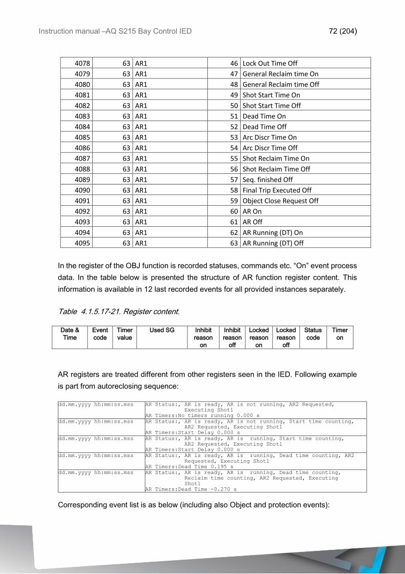
Instruction manual –AQ S215 Bay Control IED 72 (204)
4078 63 AR1 46 Lock Out Time Off
4079 63 AR1 47 General Reclaim time On
4080 63 AR1 48 General Reclaim time Off
4081 63 AR1 49 Shot Start Time On
4082 63 AR1 50 Shot Start Time Off
4083 63 AR1 51 Dead Time On
4084 63 AR1 52 Dead Time Off
4085 63 AR1 53 Arc Discr Time On
4086 63 AR1 54 Arc Discr Time Off
4087 63 AR1 55 Shot Reclaim Time On
4088 63 AR1 56 Shot Reclaim Time Off
4089 63 AR1 57 Seq. finished Off
4090 63 AR1 58 Final Trip Executed Off
4091 63 AR1 59 Object Close Request Off
4092 63 AR1 60 AR On
4093 63 AR1 61 AR Off
4094 63 AR1 62 AR Running (DT) On
4095 63 AR1 63 AR Running (DT) Off
In the register of the OBJ function is recorded statuses, commands etc. “On” event process
data. In the table below is presented the structure of AR function register content. This
information is available in 12 last recorded events for all provided instances separately.
Table 4.1.5.17-21. Register content.
Date &
Time
Event
code
Timer
value
Used SG Inhibit
reason
on
Inhibit
reason
off
Locked
reason
on
Locked
reason
off
Status
code
Timer
on
AR registers are treated different from other registers seen in the IED. Following example
is part from autoreclosing sequence:
dd.mm.yyyy hh:mm:ss.mss AR Status:, AR is ready, AR is not running, AR2 Requested,
Executing Shot1
AR Timers:No timers running 0.000 s dd.mm.yyyy hh:mm:ss.mss AR Status:, AR is ready, AR is not running, Start time counting,
AR2 Requested, Executing Shot1
AR Timers:Start Delay 0.000 s
dd.mm.yyyy hh:mm:ss.mss AR Status:, AR is ready, AR is running, Start time counting,
AR2 Requested, Executing Shot1
AR Timers:Start Delay 0.000 s
dd.mm.yyyy hh:mm:ss.mss AR Status:, AR is ready, AR is running, Dead time counting, AR2
Requested, Executing Shot1
AR Timers:Dead Time 0.195 s
dd.mm.yyyy hh:mm:ss.mss AR Status:, AR is ready, AR is running, Dead time counting,
Reclaim time counting, AR2 Requested, Executing
Shot1
AR Timers:Dead Time -0.270 s
Corresponding event list is as below (including also Object and protection events):
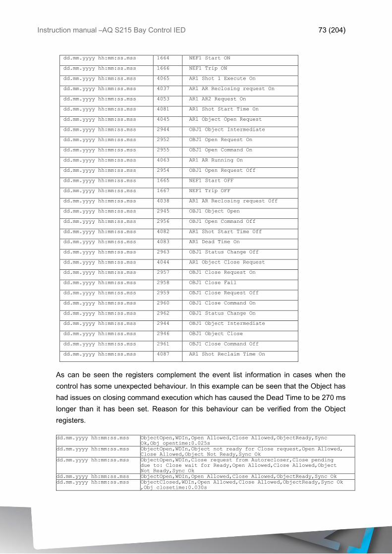
Instruction manual –AQ S215 Bay Control IED 73 (204)
dd.mm.yyyy hh:mm:ss.mss 1664 NEF1 Start ON
dd.mm.yyyy hh:mm:ss.mss 1666 NEF1 Trip ON
dd.mm.yyyy hh:mm:ss.mss 4065 AR1 Shot 1 Execute On
dd.mm.yyyy hh:mm:ss.mss 4037 AR1 AR Reclosing request On
dd.mm.yyyy hh:mm:ss.mss 4053 AR1 AR2 Request On
dd.mm.yyyy hh:mm:ss.mss 4081 AR1 Shot Start Time On
dd.mm.yyyy hh:mm:ss.mss 4045 AR1 Object Open Request
dd.mm.yyyy hh:mm:ss.mss 2944 OBJ1 Object Intermediate
dd.mm.yyyy hh:mm:ss.mss 2952 OBJ1 Open Request On
dd.mm.yyyy hh:mm:ss.mss 2955 OBJ1 Open Command On
dd.mm.yyyy hh:mm:ss.mss 4063 AR1 AR Running On
dd.mm.yyyy hh:mm:ss.mss 2954 OBJ1 Open Request Off
dd.mm.yyyy hh:mm:ss.mss 1665 NEF1 Start OFF
dd.mm.yyyy hh:mm:ss.mss 1667 NEF1 Trip OFF
dd.mm.yyyy hh:mm:ss.mss 4038 AR1 AR Reclosing request Off
dd.mm.yyyy hh:mm:ss.mss 2945 OBJ1 Object Open
dd.mm.yyyy hh:mm:ss.mss 2956 OBJ1 Open Command Off
dd.mm.yyyy hh:mm:ss.mss 4082 AR1 Shot Start Time Off
dd.mm.yyyy hh:mm:ss.mss 4083 AR1 Dead Time On
dd.mm.yyyy hh:mm:ss.mss 2963 OBJ1 Status Change Off
dd.mm.yyyy hh:mm:ss.mss 4044 AR1 Object Close Request
dd.mm.yyyy hh:mm:ss.mss 2957 OBJ1 Close Request On
dd.mm.yyyy hh:mm:ss.mss 2958 OBJ1 Close Fail
dd.mm.yyyy hh:mm:ss.mss 2959 OBJ1 Close Request Off
dd.mm.yyyy hh:mm:ss.mss 2960 OBJ1 Close Command On
dd.mm.yyyy hh:mm:ss.mss 2962 OBJ1 Status Change On
dd.mm.yyyy hh:mm:ss.mss 2944 OBJ1 Object Intermediate
dd.mm.yyyy hh:mm:ss.mss 2946 OBJ1 Object Close
dd.mm.yyyy hh:mm:ss.mss 2961 OBJ1 Close Command Off
dd.mm.yyyy hh:mm:ss.mss 4087 AR1 Shot Reclaim Time On
As can be seen the registers complement the event list information in cases when the
control has some unexpected behaviour. In this example can be seen that the Object has
had issues on closing command execution which has caused the Dead Time to be 270 ms
longer than it has been set. Reason for this behaviour can be verified from the Object
registers.
dd.mm.yyyy hh:mm:ss.mss ObjectOpen,WDIn,Open Allowed,Close Allowed,ObjectReady,Sync
Ok,Obj opentime:0.025s
dd.mm.yyyy hh:mm:ss.mss ObjectOpen,WDIn,Object not ready for Close request,Open Allowed,
Close Allowed,Object Not Ready,Sync Ok
dd.mm.yyyy hh:mm:ss.mss ObjectOpen,WDIn,Close request from Autorecloser,Close pending
due to: Close wait for Ready,Open Allowed,Close Allowed,Object
Not Ready,Sync Ok
dd.mm.yyyy hh:mm:ss.mss ObjectOpen,WDIn,Open Allowed,Close Allowed,ObjectReady,Sync Ok
dd.mm.yyyy hh:mm:ss.mss ObjectClosed,WDIn,Open Allowed,Close Allowed,ObjectReady,Sync Ok
,Obj closetime:0.030s

Instruction manual –AQ S215 Bay Control IED 74 (204)
In this case the Object was not ready when it received the closing request from autorecloser
and had the request pending until the Object was ready to execute the close command.
4.1.5.18 AUTO-RECLOSER OPERATION COUNTERS
Auto-recloser function keeps statistical track of the operated auto-reclosing cycles and
successful and failed shots.
Function records the following counters:
o Shot 1 started
o Shot 2 started
o Shot 3 started
o Shot 4 started
o Shot 5 started
o Shot 1 requested by AR1
o Shot 2 requested by AR1
o Shot 3 requested by AR1
o Shot 4 requested by AR1
o Shot 5 requested by AR1
o Shot 1 requested by AR2
o Shot 2 requested by AR2
o Shot 3 requested by AR2
o Shot 4 requested by AR2
o Shot 5 requested by AR2
o Shot 1 requested by AR3
o Shot 2 requested by AR3
o Shot 3 requested by AR3
o Shot 4 requested by AR3
o Shot 5 requested by AR3
o Shot 1 requested by AR4
o Shot 2 requested by AR4
o Shot 3 requested by AR4
o Shot 4 requested by AR4
o Shot 5 requested by AR4
o Shot 1 requested by AR5
o Shot 2 requested by AR5
o Shot 3 requested by AR5
o Shot 4 requested by AR5
o Shot 5 requested by AR5
o Shots failed
o Final Trips
o Shots cleared
o AR started
The counters are cumulative and update automatically according to the operations of the
auto-recloser function.

Instruction manual –AQ S215 Bay Control IED 75 (204)
4.1.6 COLD LOAD PICK-UP (CLPU)
Cold load pick-up function (CLPU) is used for detecting the so called “cold load” situations
which relate to the distribution feeder protection after service restoration in which loss of
load diversity has occurred. The characteristics of cold load situation will vary according to
the types of loads of individual feeders. This means that the CLPU stage needs to be set
according to the load type of the feeder it is monitoring specifically. For example in
residential areas where is possibly relatively lot of thermostat controlled apparatus, heating
or cooling machinery which normally run in asynchronous cycles. After power restoration
from longer shortage all of these devices demand full start-up power can cause the current
inrush to be significantly higher than the load current was before the shortage. In industrial
environment this kind of cases are not common since after an outage the restoration of
production process may take up to hours or even days which after the power consumption
will be in the level it was before power outage. It is also possible that in some areas of the
industrial network CLPU functionality may be useful also.
CLPU function measures constantly phase current magnitudes and magnitude changes
which on the operating decisions are based. Blocking signal and setting group selection
controls the operating characteristics of the function during normal operation.
Outputs of the function are CLPU act and Blocked signals. Setting parameters are static
inputs for the function which are changed only by user input in the setup phase of the
function. CLPU function utilizes total of eight separate setting groups which can be selected
from one common source.
The operational logic consists of input magnitude processing, threshold comparator, block
signal check, time delay characteristics and output processing.
Inputs for the function are setting parameters and measured and pre-processed current
magnitudes and binary input signals. Function outputs CLPU act and BLOCKED signals
which can be used for direct IO controlling and also for user logic programming. The function
registers its operation into 12 last time-stamped registers and also generates general time
stamped ON/OFF events to the common event buffer from each of the two output signal.
Time stamp resolution is 1ms. Function provides also cumulative counters for CLPU act
and BLOCKED events.
In the Figure 4.1.1-1 is presented the simplified function block diagram of the CLPU
function.

Instruction manual –AQ S215 Bay Control IED 76 (204)
Figure 4.1.6-28 Simplified function block diagram of the CLPU function.
4.1.6.1 MEASURED INPUT VALUES
Function block uses analog current measurement values. Function block always utilizes
peak-to-peak measurement from samples and by user selection the monitored magnitude
can be either fundamental frequency RMS values, True RMS values from the whole
harmonic specter of 32 components or peak to peak values. -20ms averaged value of the
selected magnitude is used for pre-fault data registering.
Table 4.1.6.1-22 Analogic magnitudes used by the CLPU function.
Signal Description Time base
IL1RMS Fundamental RMS measurement of phase L1/A current 5 ms
IL2RMS Fundamental RMS measurement of phase L2/B current 5 ms
IL3RMS Fundamental RMS measurement of phase L3/C current 5 ms
Selection of the used AI channel is made with a setting parameter. In all possible input
channel variations pre-fault condition is presented with 20 ms averaged history value from
-20 ms of Start or Trip event.
4.1.6.2 PICK-UP CHARACTERISTICS
Pick-up and activation of the CLPU function is controlled by ILow, IHigh and IOver setting
parameters, which defines the maximum and minimum allowed measured current before
action from the function. The function constantly calculates the ratio in between of the
setting values and measured magnitude (Im) per all three phases. Reset ratio of 97 % is
inbuilt in the function and is always related to the setting value. The setting value is common
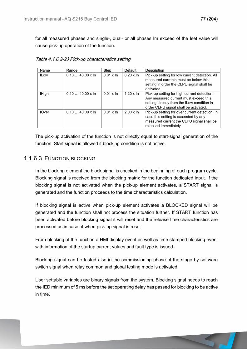
Instruction manual –AQ S215 Bay Control IED 77 (204)
for all measured phases and single-, dual- or all phases Im exceed of the Iset value will
cause pick-up operation of the function.
Table 4.1.6.2-23 Pick-up characteristics setting
Name Range Step Default Description
ILow 0.10 … 40.00 x In 0.01 x In 0.20 x In Pick-up setting for low current detection. All
measured currents must be below this
setting in order the CLPU signal shall be
activated.
IHigh 0.10 … 40.00 x In 0.01 x In 1.20 x In Pick-up setting for high current detection.
Any measured current must exceed this
setting directly from the ILow condition in
order CLPU signal shall be activated.
IOver 0.10 … 40.00 x In 0.01 x In 2.00 x In Pick-up setting for over current detection. In
case this setting is exceeded by any
measured current the CLPU signal shall be
released immediately.
The pick-up activation of the function is not directly equal to start-signal generation of the
function. Start signal is allowed if blocking condition is not active.
4.1.6.3 FUNCTION BLOCKING
In the blocking element the block signal is checked in the beginning of each program cycle.
Blocking signal is received from the blocking matrix for the function dedicated input. If the
blocking signal is not activated when the pick-up element activates, a START signal is
generated and the function proceeds to the time characteristics calculation.
If blocking signal is active when pick-up element activates a BLOCKED signal will be
generated and the function shall not process the situation further. If START function has
been activated before blocking signal it will reset and the release time characteristics are
processed as in case of when pick-up signal is reset.
From blocking of the function a HMI display event as well as time stamped blocking event
with information of the startup current values and fault type is issued.
Blocking signal can be tested also in the commissioning phase of the stage by software
switch signal when relay common and global testing mode is activated.
User settable variables are binary signals from the system. Blocking signal needs to reach
the IED minimum of 5 ms before the set operating delay has passed for blocking to be active
in time.
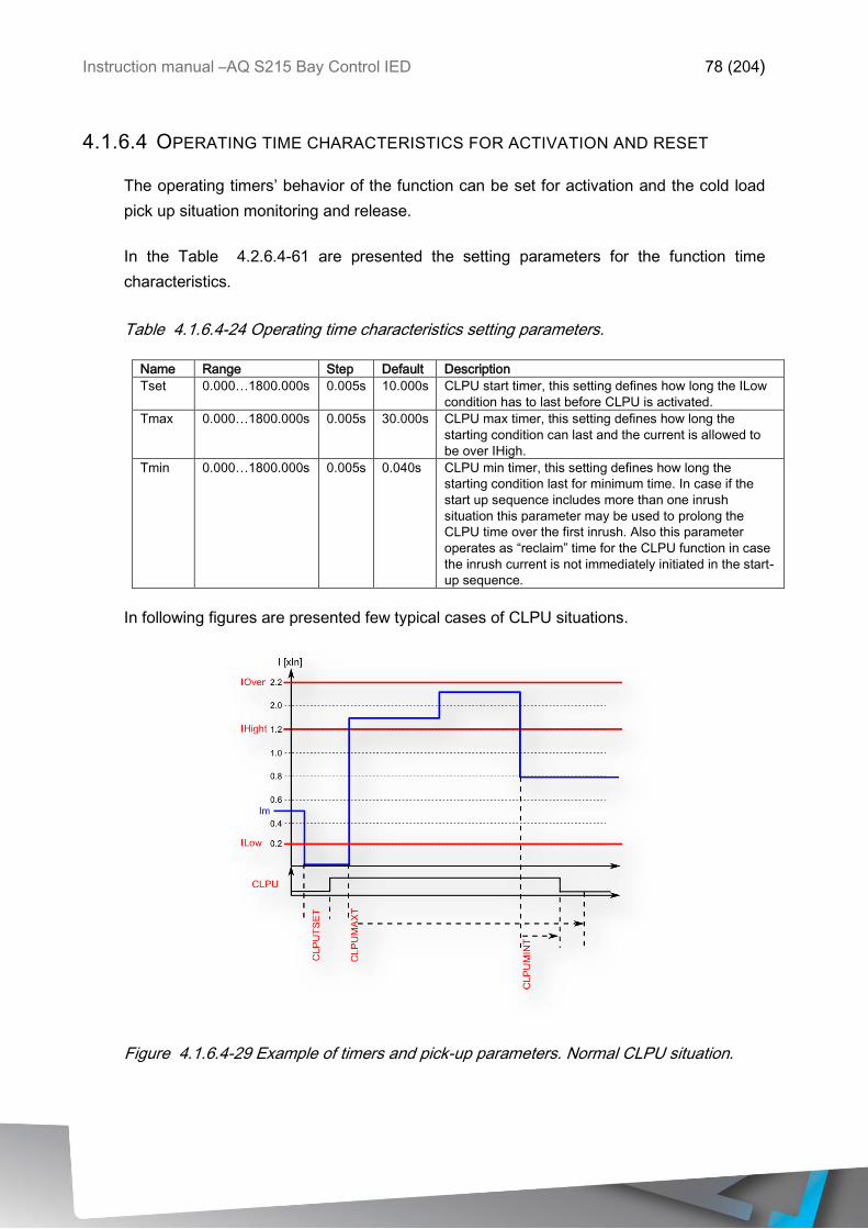
Instruction manual –AQ S215 Bay Control IED 78 (204)
4.1.6.4 OPERATING TIME CHARACTERISTICS FOR ACTIVATION AND RESET
The operating timers’ behavior of the function can be set for activation and the cold load
pick up situation monitoring and release.
In the Table 4.2.6.4-61 are presented the setting parameters for the function time
characteristics.
Table 4.1.6.4-24 Operating time characteristics setting parameters.
Name Range Step Default Description
Tset 0.000…1800.000s 0.005s 10.000s CLPU start timer, this setting defines how long the ILow
condition has to last before CLPU is activated.
Tmax 0.000…1800.000s 0.005s 30.000s CLPU max timer, this setting defines how long the
starting condition can last and the current is allowed to
be over IHigh.
Tmin 0.000…1800.000s 0.005s 0.040s CLPU min timer, this setting defines how long the
starting condition last for minimum time. In case if the
start up sequence includes more than one inrush
situation this parameter may be used to prolong the
CLPU time over the first inrush. Also this parameter
operates as “reclaim” time for the CLPU function in case
the inrush current is not immediately initiated in the start-
up sequence.
In following figures are presented few typical cases of CLPU situations.
Figure 4.1.6.4-29 Example of timers and pick-up parameters. Normal CLPU situation.
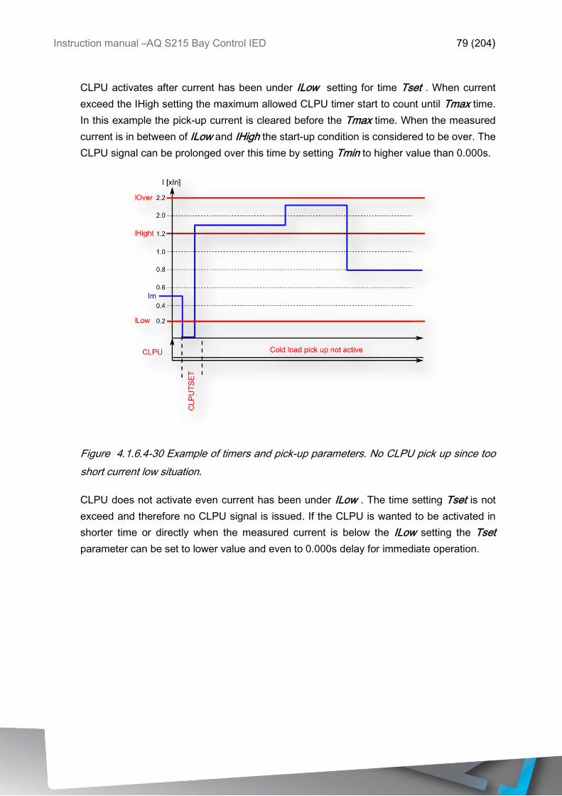
Instruction manual –AQ S215 Bay Control IED 79 (204)
CLPU activates after current has been under ILow setting for time Tset . When current
exceed the IHigh setting the maximum allowed CLPU timer start to count until Tmax time.
In this example the pick-up current is cleared before the Tmax time. When the measured
current is in between of ILow and IHigh the start-up condition is considered to be over. The
CLPU signal can be prolonged over this time by setting Tmin to higher value than 0.000s.
Figure 4.1.6.4-30 Example of timers and pick-up parameters. No CLPU pick up since too
short current low situation.
CLPU does not activate even current has been under ILow . The time setting Tset is not
exceed and therefore no CLPU signal is issued. If the CLPU is wanted to be activated in
shorter time or directly when the measured current is below the ILow setting the Tset
parameter can be set to lower value and even to 0.000s delay for immediate operation.
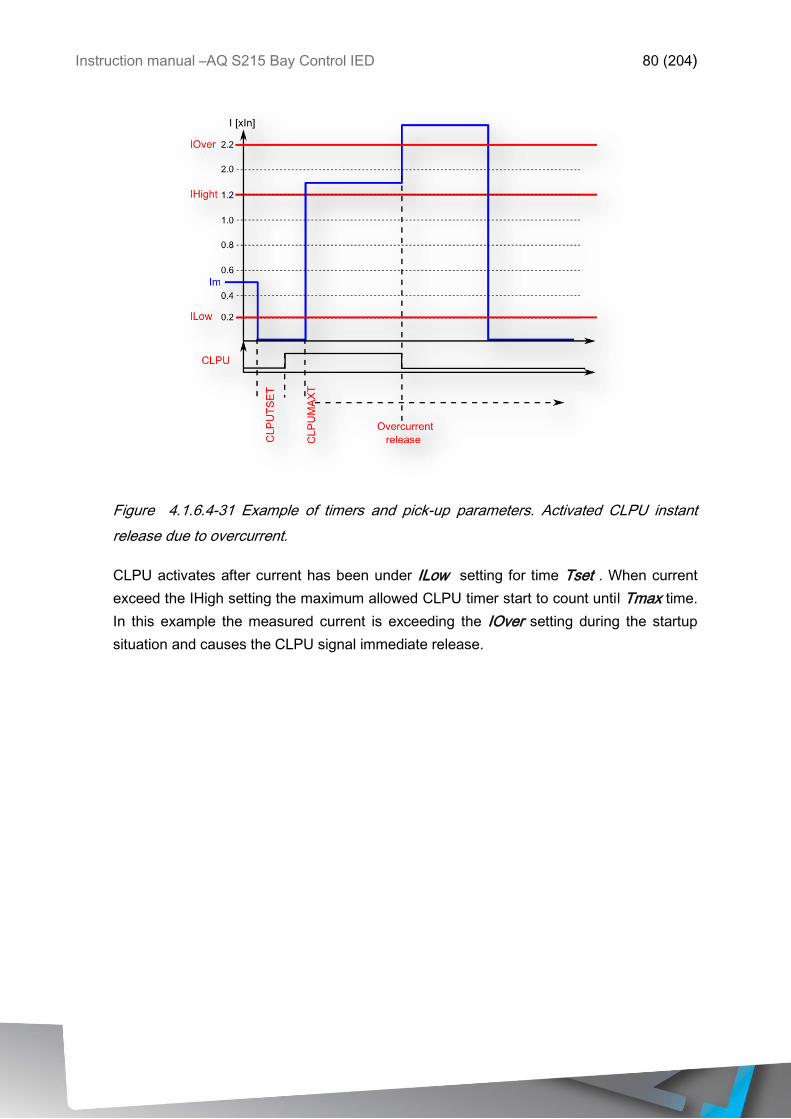
Instruction manual –AQ S215 Bay Control IED 80 (204)
Figure 4.1.6.4-31 Example of timers and pick-up parameters. Activated CLPU instant
release due to overcurrent.
CLPU activates after current has been under ILow setting for time Tset . When current
exceed the IHigh setting the maximum allowed CLPU timer start to count until Tmax time.
In this example the measured current is exceeding the IOver setting during the startup
situation and causes the CLPU signal immediate release.

Instruction manual –AQ S215 Bay Control IED 81 (204)
Figure 4.1.6.4-32 Example of timers and pick-up parameters. Activated CLPU instant
release due to too long starting.
CLPU activates after current has been under ILow setting for time Tset . When current
exceed the IHigh setting the maximum allowed CLPU timer start to count until Tmax time.
In this example the measured current is over the set IHigh setting until Tmax time and
causes the release of the CLPU signal.
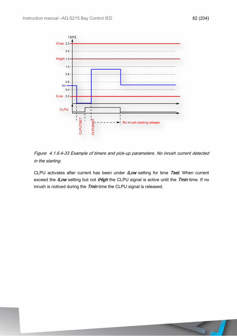
Instruction manual –AQ S215 Bay Control IED 82 (204)
Figure 4.1.6.4-33 Example of timers and pick-up parameters. No inrush current detected
in the starting.
CLPU activates after current has been under ILow setting for time Tset. When current
exceed the ILow setting but not IHigh the CLPU signal is active until the Tmin time. If no
inrush is noticed during the Tmin time the CLPU signal is released.
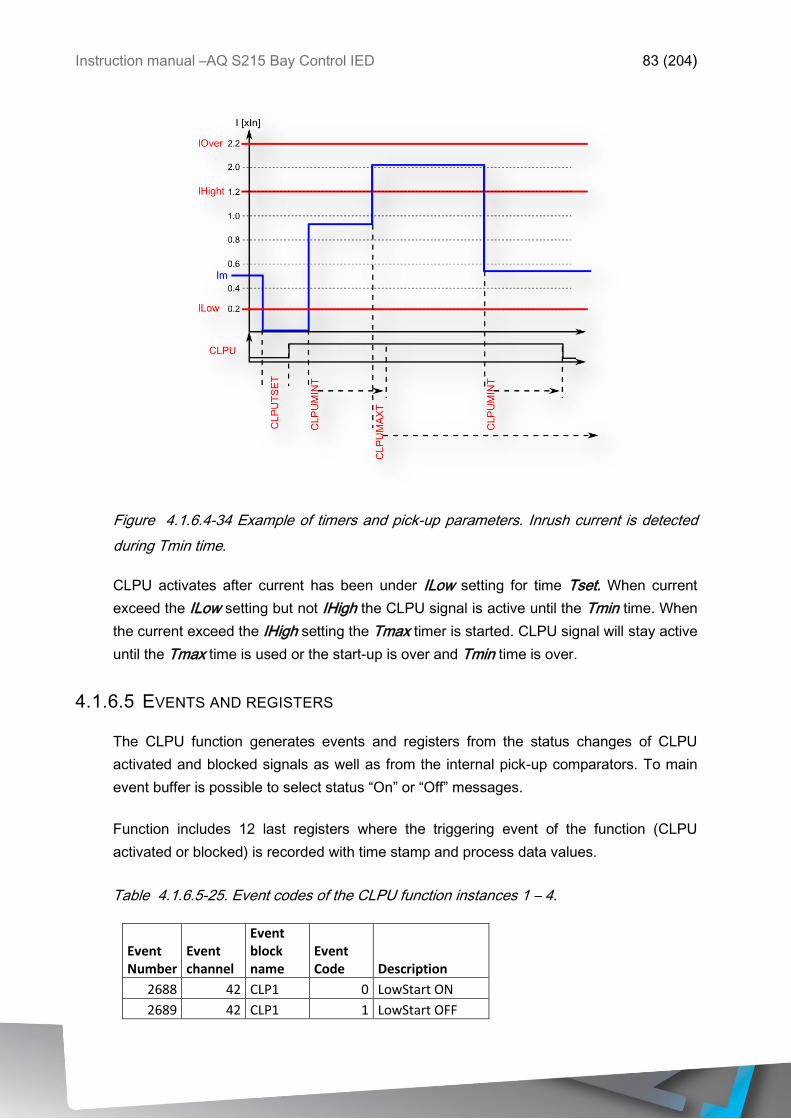
Instruction manual –AQ S215 Bay Control IED 83 (204)
Figure 4.1.6.4-34 Example of timers and pick-up parameters. Inrush current is detected
during Tmin time.
CLPU activates after current has been under ILow setting for time Tset. When current
exceed the ILow setting but not IHigh the CLPU signal is active until the Tmin time. When
the current exceed the IHigh setting the Tmax timer is started. CLPU signal will stay active
until the Tmax time is used or the start-up is over and Tmin time is over.
4.1.6.5 EVENTS AND REGISTERS
The CLPU function generates events and registers from the status changes of CLPU
activated and blocked signals as well as from the internal pick-up comparators. To main
event buffer is possible to select status “On” or “Off” messages.
Function includes 12 last registers where the triggering event of the function (CLPU
activated or blocked) is recorded with time stamp and process data values.
Table 4.1.6.5-25. Event codes of the CLPU function instances 1 – 4.
Event Number
Event channel
Event block name
Event Code Description
2688 42 CLP1 0 LowStart ON
2689 42 CLP1 1 LowStart OFF
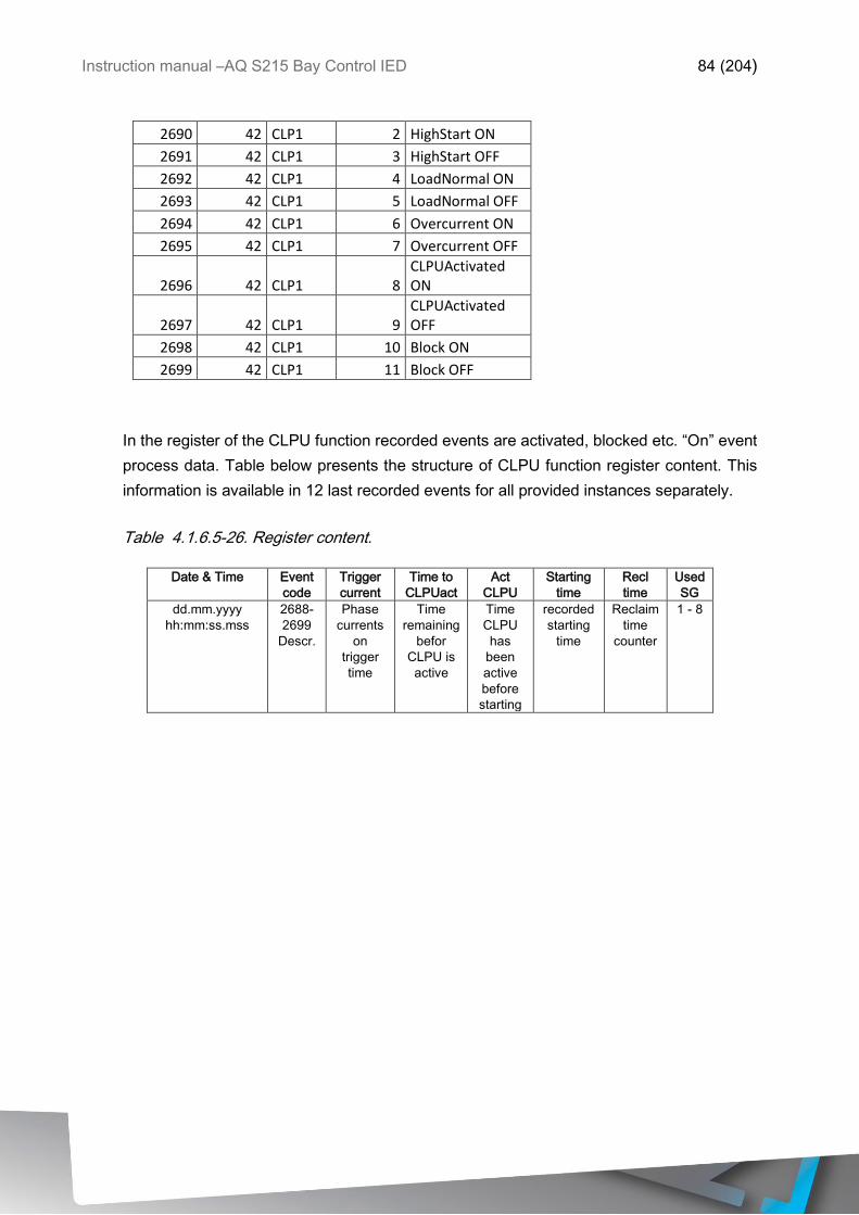
Instruction manual –AQ S215 Bay Control IED 84 (204)
2690 42 CLP1 2 HighStart ON
2691 42 CLP1 3 HighStart OFF
2692 42 CLP1 4 LoadNormal ON
2693 42 CLP1 5 LoadNormal OFF
2694 42 CLP1 6 Overcurrent ON
2695 42 CLP1 7 Overcurrent OFF
2696 42 CLP1 8 CLPUActivated ON
2697 42 CLP1 9 CLPUActivated OFF
2698 42 CLP1 10 Block ON
2699 42 CLP1 11 Block OFF
In the register of the CLPU function recorded events are activated, blocked etc. “On” event
process data. Table below presents the structure of CLPU function register content. This
information is available in 12 last recorded events for all provided instances separately.
Table 4.1.6.5-26. Register content.
Date & Time Event
code
Trigger
current
Time to
CLPUact
Act
CLPU
Starting
time
Recl
time
Used
SG
dd.mm.yyyy
hh:mm:ss.mss
2688-
2699
Descr.
Phase
currents
on
trigger
time
Time
remaining
befor
CLPU is
active
Time
CLPU
has
been
active
before
starting
recorded
starting
time
Reclaim
time
counter
1 - 8
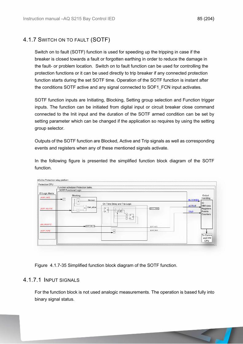
Instruction manual –AQ S215 Bay Control IED 85 (204)
4.1.7 SWITCH ON TO FAULT (SOTF)
Switch on to fault (SOTF) function is used for speeding up the tripping in case if the
breaker is closed towards a fault or forgotten earthing in order to reduce the damage in
the fault- or problem location. Switch on to fault function can be used for controlling the
protection functions or it can be used directly to trip breaker if any connected protection
function starts during the set SOTF time. Operation of the SOTF function is instant after
the conditions SOTF active and any signal connected to SOF1_FCN input activates.
SOTF function inputs are Initiating, Blocking, Setting group selection and Function trigger
inputs. The function can be initiated from digital input or circuit breaker close command
connected to the Init input and the duration of the SOTF armed condition can be set by
setting parameter which can be changed if the application so requires by using the setting
group selector.
Outputs of the SOTF function are Blocked, Active and Trip signals as well as corresponding
events and registers when any of these mentioned signals activate.
In the following figure is presented the simplified function block diagram of the SOTF
function.
Figure 4.1.7-35 Simplified function block diagram of the SOTF function.
4.1.7.1 INPUT SIGNALS
For the function block is not used analogic measurements. The operation is based fully into
binary signal status.
Instruction manual –AQ S215 Bay Control IED 86 (204)
Table 4.1.7.1-27 Signal inputs used by the SOTF function.
Input Description
SOTF activate
input
Binary input for the function to arm and start calculate the SOTF time. Any binary
signal can be used to activate SOTF and start the calculation. Start of the function is
applied from rising edge of the signal.
Block input Input for blocking SOTF function. Any binary signal can be used to block SOTF
function from starting.
Function input Function input for SOTF activates SOTF instant trip if applied simultaneously when
the SOTF function is calculating SOTF time.
4.1.7.2 SETTINGS
Setting for the SOTF function is the active time after function is triggered. During this time
if any set signal to Function input activates SOTF trip will be activated.
Name Range Step Default Description
Release time
for SOTF
0.000…1800.000s 0.005 s 1.000 s SOTF active time after triggering.
4.1.7.3 FUNCTION BLOCKING
SOTF function can be blocked by activating BLOCK input. This will prevent the SOTF active
time from starting.
4.1.7.4 EVENTS AND REGISTERS
The SOTF function generates events and registers from the status changes of SOTF
activated, SOTF trip and blocked. To main event buffer is possible to select status “On” or
“Off” messages.
In the function is available 12 last registers where the triggering event of the function is
recorded with time stamp and process data values.
Table 4.1.7.4-28. Event codes of the SOTF-function instance
Event Number
Event channel
Event block name
Event Code Description
3904 61 SOF1 0 SOTF Init On
3905 61 SOF1 1 SOTF Init Off
3906 61 SOF1 2 SOTF Block On
3907 61 SOF1 3 SOTF Block Off
3908 61 SOF1 4 SOTF Active On
3909 61 SOF1 5 SOTF Active Off
3910 61 SOF1 6 SOTF Trip On
Instruction manual –AQ S215 Bay Control IED 87 (204)
3911 61 SOF1 7 SOTF Trip Off
In the register of the SOTF function is recorded activated “On” event process data. In the
table below is presented the structure of SOTF function register content. This information
is available in 12 last recorded events for all provided instances separately.
Table 4.1.7.4-29. Register content.
Date & Time Event
code
SG in
use
SOTF
remaining
time
SOTF
been
active
time
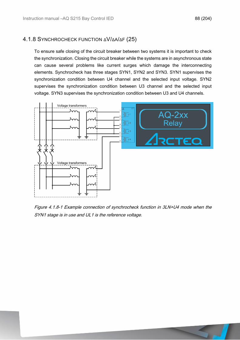
Instruction manual –AQ S215 Bay Control IED 88 (204)
4.1.8 SYNCHROCHECK FUNCTION ΔV/ΔA/ΔF (25)
To ensure safe closing of the circuit breaker between two systems it is important to check
the synchronization. Closing the circuit breaker while the systems are in asynchronous state
can cause several problems like current surges which damage the interconnecting
elements. Synchrocheck has three stages SYN1, SYN2 and SYN3. SYN1 supervises the
synchronization condition between U4 channel and the selected input voltage. SYN2
supervises the synchronization condition between U3 channel and the selected input
voltage. SYN3 supervises the synchronization condition between U3 and U4 channels.
Figure 4.1.8-1 Example connection of synchrocheck function in 3LN+U4 mode when the
SYN1 stage is in use and UL1 is the reference voltage.
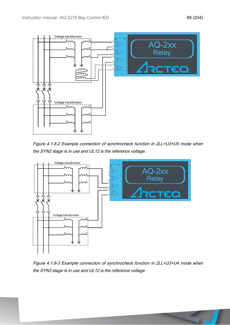
Instruction manual –AQ S215 Bay Control IED 89 (204)
Figure 4.1.8-2 Example connection of synchrocheck function in 2LL+U3+U0 mode when
the SYN2 stage is in use and UL12 is the reference voltage.
Figure 4.1.8-3 Example connection of synchrocheck function in 2LL+U3+U4 mode when
the SYN3 stage is in use and UL12 is the reference voltage.
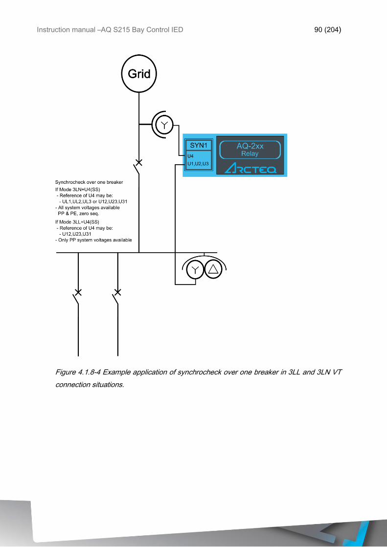
Instruction manual –AQ S215 Bay Control IED 90 (204)
Figure 4.1.8-4 Example application of synchrocheck over one breaker in 3LL and 3LN VT
connection situations.
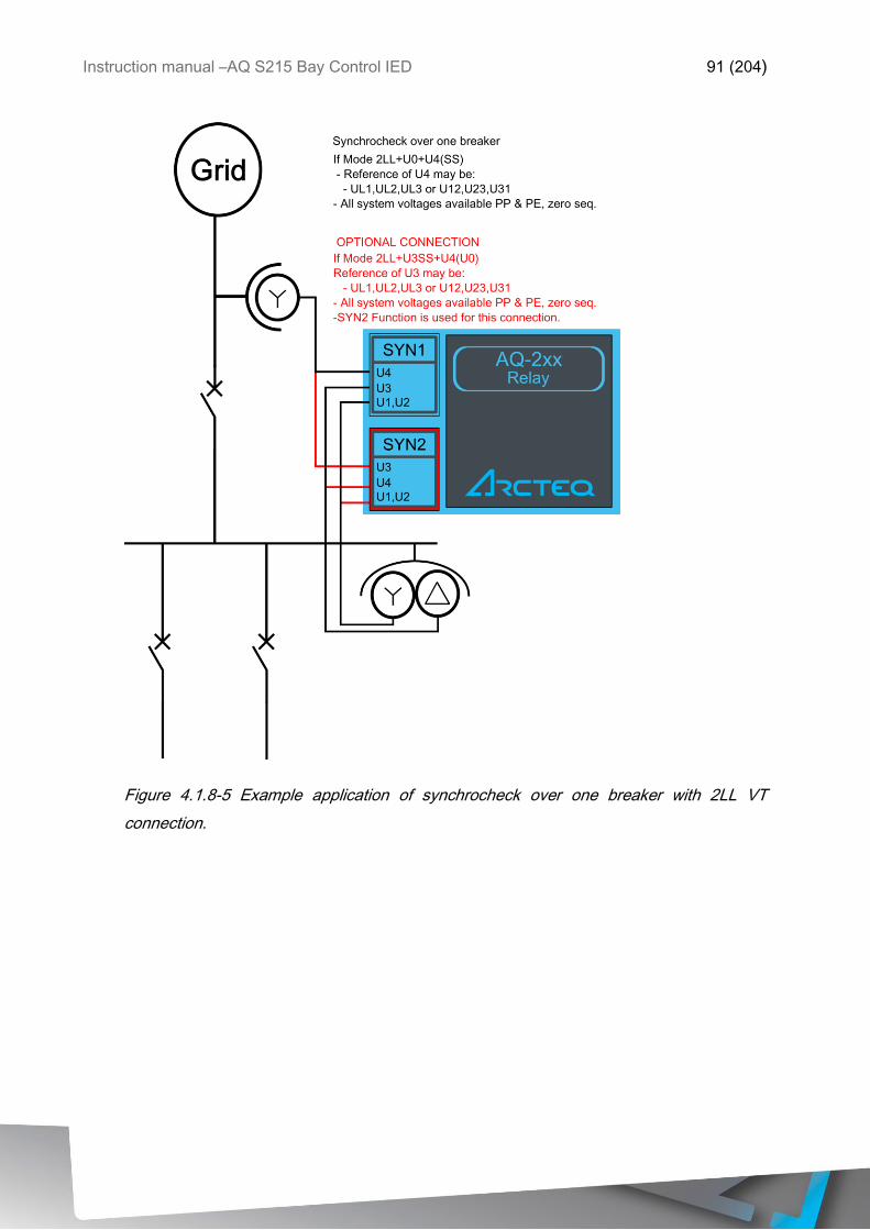
Instruction manual –AQ S215 Bay Control IED 91 (204)
Figure 4.1.8-5 Example application of synchrocheck over one breaker with 2LL VT
connection.
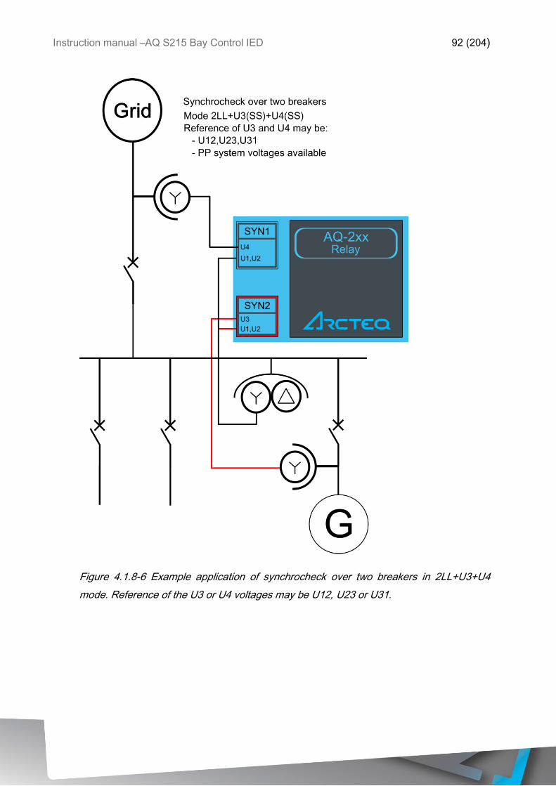
Instruction manual –AQ S215 Bay Control IED 92 (204)
Figure 4.1.8-6 Example application of synchrocheck over two breakers in 2LL+U3+U4
mode. Reference of the U3 or U4 voltages may be U12, U23 or U31.
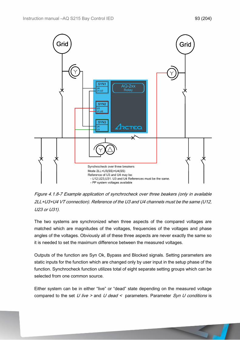
Instruction manual –AQ S215 Bay Control IED 93 (204)
Figure 4.1.8-7 Example application of synchrocheck over three beakers (only in available
2LL+U3+U4 VT connection). Reference of the U3 and U4 channels must be the same (U12,
U23 or U31).
The two systems are synchronized when three aspects of the compared voltages are
matched which are magnitudes of the voltages, frequencies of the voltages and phase
angles of the voltages. Obviously all of these three aspects are never exactly the same so
it is needed to set the maximum difference between the measured voltages.
Outputs of the function are Syn Ok, Bypass and Blocked signals. Setting parameters are
static inputs for the function which are changed only by user input in the setup phase of the
function. Synchrocheck function utilizes total of eight separate setting groups which can be
selected from one common source.
Either system can be in either “live” or “dead” state depending on the measured voltage
compared to the set U live > and U dead < parameters. Parameter Syn U conditions is
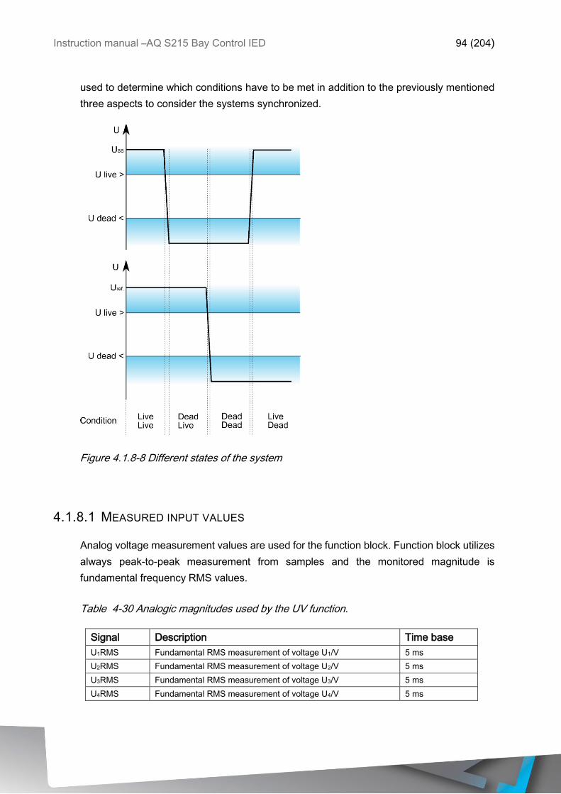
Instruction manual –AQ S215 Bay Control IED 94 (204)
used to determine which conditions have to be met in addition to the previously mentioned
three aspects to consider the systems synchronized.
Figure 4.1.8-8 Different states of the system
4.1.8.1 MEASURED INPUT VALUES
Analog voltage measurement values are used for the function block. Function block utilizes
always peak-to-peak measurement from samples and the monitored magnitude is
fundamental frequency RMS values.
Table 4-30 Analogic magnitudes used by the UV function.
Signal Description Time base
U1RMS Fundamental RMS measurement of voltage U1/V 5 ms
U2RMS Fundamental RMS measurement of voltage U2/V 5 ms
U3RMS Fundamental RMS measurement of voltage U3/V 5 ms
U4RMS Fundamental RMS measurement of voltage U4/V 5 ms
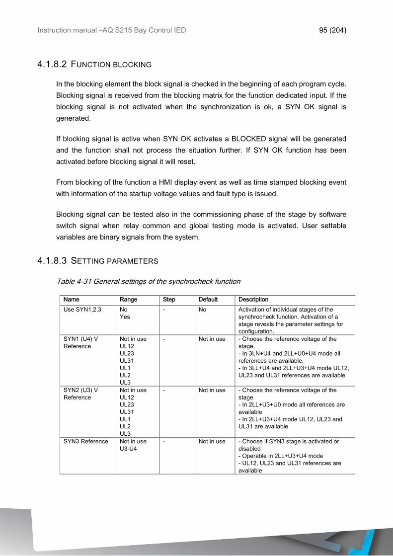
Instruction manual –AQ S215 Bay Control IED 95 (204)
4.1.8.2 FUNCTION BLOCKING
In the blocking element the block signal is checked in the beginning of each program cycle.
Blocking signal is received from the blocking matrix for the function dedicated input. If the
blocking signal is not activated when the synchronization is ok, a SYN OK signal is
generated.
If blocking signal is active when SYN OK activates a BLOCKED signal will be generated
and the function shall not process the situation further. If SYN OK function has been
activated before blocking signal it will reset.
From blocking of the function a HMI display event as well as time stamped blocking event
with information of the startup voltage values and fault type is issued.
Blocking signal can be tested also in the commissioning phase of the stage by software
switch signal when relay common and global testing mode is activated. User settable
variables are binary signals from the system.
4.1.8.3 SETTING PARAMETERS
Table 4-31 General settings of the synchrocheck function
Name Range Step Default Description
Use SYN1,2,3 No
Yes
- No Activation of individual stages of the
synchrocheck function. Activation of a
stage reveals the parameter settings for
configuration.
SYN1 (U4) V
Reference
Not in use
UL12
UL23
UL31
UL1
UL2
UL3
- Not in use - Choose the reference voltage of the
stage.
- In 3LN+U4 and 2LL+U0+U4 mode all
references are available.
- In 3LL+U4 and 2LL+U3+U4 mode UL12,
UL23 and UL31 references are available
SYN2 (U3) V
Reference
Not in use
UL12
UL23
UL31
UL1
UL2
UL3
- Not in use - Choose the reference voltage of the
stage.
- In 2LL+U3+U0 mode all references are
available
- In 2LL+U3+U4 mode UL12, UL23 and
UL31 are available
SYN3 Reference Not in use
U3-U4
- Not in use - Choose if SYN3 stage is activated or
disabled
- Operable in 2LL+U3+U4 mode
- UL12, UL23 and UL31 references are
available
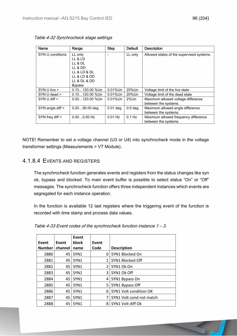
Instruction manual –AQ S215 Bay Control IED 96 (204)
Table 4-32 Synchrocheck stage settings
Name Range Step Default Description
SYN U conditions LL only
LL & LD
LL & DL
LL & DD
LL & LD & DL
LL & LD & DD
LL & DL & DD
Bypass
- LL only Allowed states of the supervised systems.
SYN U live > 0.10…120.00 %Un 0.01%Un 20%Un Voltage limit of the live state
SYN U dead < 0.10…120.00 %Un 0.01%Un 20%Un Voltage limit of the dead state
SYN U diff < 0.00…120.00 %Un 0.01%Un 2%Un Maximum allowed voltage difference
between the systems.
SYN angle diff < 0.00…90.00 deg 0.01 deg 0.5 deg Maximum allowed angle difference
between the systems.
SYN freq diff < 0.00…0.50 Hz 0.01 Hz 0.1 Hz Maximum allowed frequency difference
between the systems.
NOTE! Remember to set a voltage channel (U3 or U4) into synchrocheck mode in the voltage
transformer settings (Measurements > VT Module).
4.1.8.4 EVENTS AND REGISTERS
The synchrocheck function generates events and registers from the status changes like syn
ok, bypass and blocked. To main event buffer is possible to select status “On” or “Off”
messages. The synchrocheck function offers three independent instances which events are
segregated for each instance operation.
In the function is available 12 last registers where the triggering event of the function is
recorded with time stamp and process data values.
Table 4-33 Event codes of the synchrocheck function instance 1 – 3.
Event Number
Event channel
Event block name
Event Code Description
2880 45 SYN1 0 SYN1 Blocked On
2881 45 SYN1 1 SYN1 Blocked Off
2882 45 SYN1 2 SYN1 Ok On
2883 45 SYN1 3 SYN1 Ok Off
2884 45 SYN1 4 SYN1 Bypass On
2885 45 SYN1 5 SYN1 Bypass Off
2886 45 SYN1 6 SYN1 Volt condition OK
2887 45 SYN1 7 SYN1 Volt cond not match
2888 45 SYN1 8 SYN1 Volt diff Ok
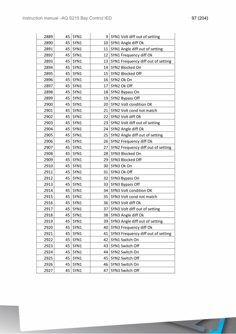
Instruction manual –AQ S215 Bay Control IED 97 (204)
2889 45 SYN1 9 SYN1 Volt diff out of setting
2890 45 SYN1 10 SYN1 Angle diff Ok
2891 45 SYN1 11 SYN1 Angle diff out of setting
2892 45 SYN1 12 SYN1 Frequency diff Ok
2893 45 SYN1 13 SYN1 Frequency diff out of setting
2894 45 SYN1 14 SYN2 Blocked On
2895 45 SYN1 15 SYN2 Blocked Off
2896 45 SYN1 16 SYN2 Ok On
2897 45 SYN1 17 SYN2 Ok Off
2898 45 SYN1 18 SYN2 Bypass On
2899 45 SYN1 19 SYN2 Bypass Off
2900 45 SYN1 20 SYN2 Volt condition OK
2901 45 SYN1 21 SYN2 Volt cond not match
2902 45 SYN1 22 SYN2 Volt diff Ok
2903 45 SYN1 23 SYN2 Volt diff out of setting
2904 45 SYN1 24 SYN2 Angle diff Ok
2905 45 SYN1 25 SYN2 Angle diff out of setting
2906 45 SYN1 26 SYN2 Frequency diff Ok
2907 45 SYN1 27 SYN2 Frequency diff out of setting
2908 45 SYN1 28 SYN3 Blocked On
2909 45 SYN1 29 SYN3 Blocked Off
2910 45 SYN1 30 SYN3 Ok On
2911 45 SYN1 31 SYN3 Ok Off
2912 45 SYN1 32 SYN3 Bypass On
2913 45 SYN1 33 SYN3 Bypass Off
2914 45 SYN1 34 SYN3 Volt condition OK
2915 45 SYN1 35 SYN3 Volt cond not match
2916 45 SYN1 36 SYN3 Volt diff Ok
2917 45 SYN1 37 SYN3 Volt diff out of setting
2918 45 SYN1 38 SYN3 Angle diff Ok
2919 45 SYN1 39 SYN3 Angle diff out of setting
2920 45 SYN1 40 SYN3 Frequency diff Ok
2921 45 SYN1 41 SYN3 Frequency diff out of setting
2922 45 SYN1 42 SYN1 Switch On
2923 45 SYN1 43 SYN1 Switch Off
2924 45 SYN1 44 SYN2 Switch On
2925 45 SYN1 45 SYN2 Switch Off
2926 45 SYN1 46 SYN3 Switch On
2927 45 SYN1 47 SYN3 Switch Off
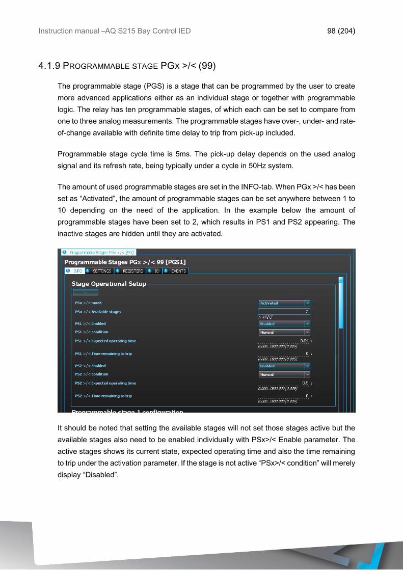
Instruction manual –AQ S215 Bay Control IED 98 (204)
4.1.9 PROGRAMMABLE STAGE PGX >/< (99)
The programmable stage (PGS) is a stage that can be programmed by the user to create
more advanced applications either as an individual stage or together with programmable
logic. The relay has ten programmable stages, of which each can be set to compare from
one to three analog measurements. The programmable stages have over-, under- and rate-
of-change available with definite time delay to trip from pick-up included.
Programmable stage cycle time is 5ms. The pick-up delay depends on the used analog
signal and its refresh rate, being typically under a cycle in 50Hz system.
The amount of used programmable stages are set in the INFO-tab. When PGx >/< has been
set as “Activated”, the amount of programmable stages can be set anywhere between 1 to
10 depending on the need of the application. In the example below the amount of
programmable stages have been set to 2, which results in PS1 and PS2 appearing. The
inactive stages are hidden until they are activated.
It should be noted that setting the available stages will not set those stages active but the
available stages also need to be enabled individually with PSx>/< Enable parameter. The
active stages shows its current state, expected operating time and also the time remaining
to trip under the activation parameter. If the stage is not active “PSx>/< condition” will merely
display “Disabled”.
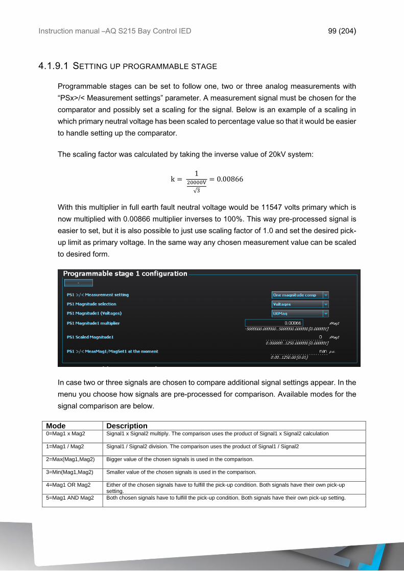
Instruction manual –AQ S215 Bay Control IED 99 (204)
4.1.9.1 SETTING UP PROGRAMMABLE STAGE
Programmable stages can be set to follow one, two or three analog measurements with
“PSx>/< Measurement settings” parameter. A measurement signal must be chosen for the
comparator and possibly set a scaling for the signal. Below is an example of a scaling in
which primary neutral voltage has been scaled to percentage value so that it would be easier
to handle setting up the comparator.
The scaling factor was calculated by taking the inverse value of 20kV system:
k = 1
20000V
√3
= 0.00866
With this multiplier in full earth fault neutral voltage would be 11547 volts primary which is
now multiplied with 0.00866 multiplier inverses to 100%. This way pre-processed signal is
easier to set, but it is also possible to just use scaling factor of 1.0 and set the desired pick-
up limit as primary voltage. In the same way any chosen measurement value can be scaled
to desired form.
In case two or three signals are chosen to compare additional signal settings appear. In the
menu you choose how signals are pre-processed for comparison. Available modes for the
signal comparison are below.
Mode Description 0=Mag1 x Mag2
Signal1 x Signal2 multiply. The comparison uses the product of Signal1 x Signal2 calculation
1=Mag1 / Mag2
Signal1 / Signal2 division. The comparison uses the product of Signal1 / Signal2
2=Max(Mag1,Mag2)
Bigger value of the chosen signals is used in the comparison.
3=Min(Mag1,Mag2)
Smaller value of the chosen signals is used in the comparison.
4=Mag1 OR Mag2
Either of the chosen signals have to fulfill the pick-up condition. Both signals have their own pick-up setting.
5=Mag1 AND Mag2
Both chosen signals have to fulfill the pick-up condition. Both signals have their own pick-up setting.
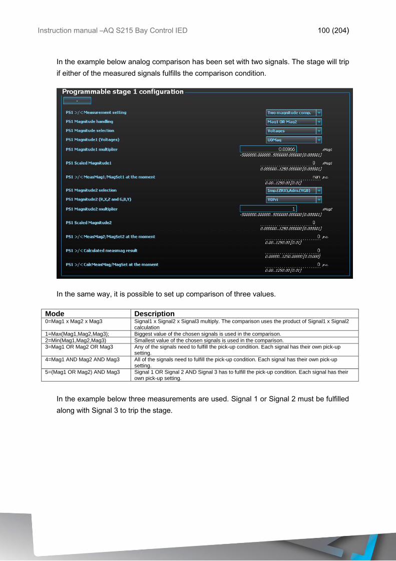
Instruction manual –AQ S215 Bay Control IED 100 (204)
In the example below analog comparison has been set with two signals. The stage will trip
if either of the measured signals fulfills the comparison condition.
In the same way, it is possible to set up comparison of three values.
Mode Description 0=Mag1 x Mag2 x Mag3 Signal1 x Signal2 x Signal3 multiply. The comparison uses the product of Signal1 x Signal2
calculation
1=Max(Mag1,Mag2,Mag3); Biggest value of the chosen signals is used in the comparison.
2=Min(Mag1,Mag2,Mag3) Smallest value of the chosen signals is used in the comparison.
3=Mag1 OR Mag2 OR Mag3 Any of the signals need to fulfill the pick-up condition. Each signal has their own pick-up setting.
4=Mag1 AND Mag2 AND Mag3 All of the signals need to fulfill the pick-up condition. Each signal has their own pick-up setting.
5=(Mag1 OR Mag2) AND Mag3 Signal 1 OR Signal 2 AND Signal 3 has to fulfill the pick-up condition. Each signal has their own pick-up setting.
In the example below three measurements are used. Signal 1 or Signal 2 must be fulfilled
along with Signal 3 to trip the stage.
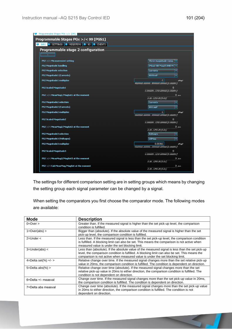
Instruction manual –AQ S215 Bay Control IED 101 (204)
The settings for different comparison setting are in setting groups which means by changing
the setting group each signal parameter can be changed by a signal.
When setting the comparators you first choose the comparator mode. The following modes
are available:
Mode Description 0=Over > Greater than. If the measured signal is higher than the set pick-up level, the comparison
condition is fulfilled.
1=Over(abs) > Bigger than (absolute). If the absolute value of the measured signal is higher than the set pick-up level, the comparison condition is fulfilled.
2=Under < Less than. If the measured signal is less than the set pick-up level, the comparison condition is fulfilled. A blocking limit can also be set. This means the comparison is not active when measured value is under the set blocking limit.
3=Under(abs) < Less than (absolute). If the absolute value of the measured signal is less than the set pick-up level, the comparison condition is fulfilled. A blocking limit can also be set. This means the comparison is not active when measured value is under the set blocking limit.
4=Delta set(%) +/- > Relative change over time. If the measured signal changes more than the set relative pick-up value in 20ms, the comparison condition is fulfilled. The condition is dependent on direction.
5=Delta abs(%) > Relative change over time (absolute). If the measured signal changes more than the set relative pick-up value in 20ms to either direction, the comparison condition is fulfilled. The condition is not dependent on direction.
6=Delta +/- measval Change over time. If the measured signal changes more than the set pick-up value in 20ms, the comparison condition is fulfilled. The condition is dependent on direction.
7=Delta abs measval Change over time (absolute). If the measured signal changes more than the set pick-up value in 20ms to either direction, the comparison condition is fulfilled. The condition is not dependent on direction.
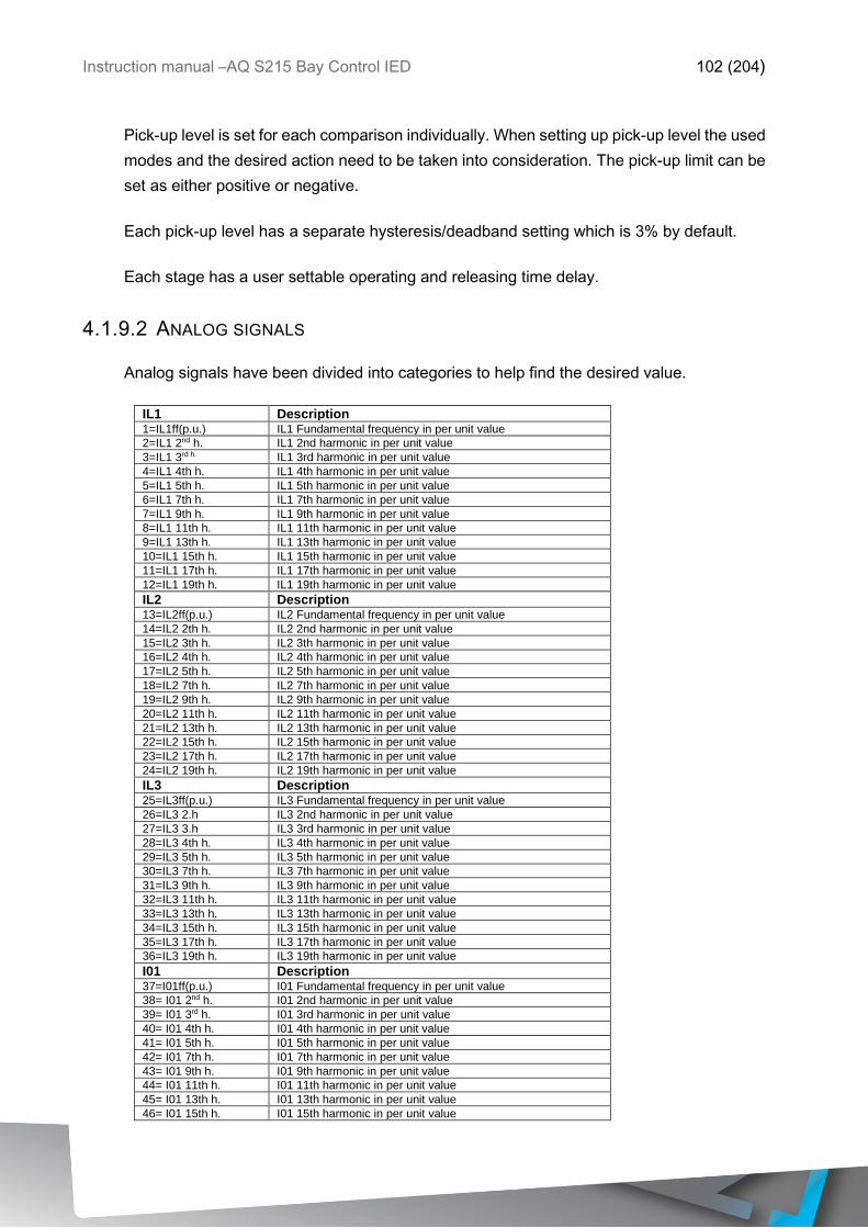
Instruction manual –AQ S215 Bay Control IED 102 (204)
Pick-up level is set for each comparison individually. When setting up pick-up level the used
modes and the desired action need to be taken into consideration. The pick-up limit can be
set as either positive or negative.
Each pick-up level has a separate hysteresis/deadband setting which is 3% by default.
Each stage has a user settable operating and releasing time delay.
4.1.9.2 ANALOG SIGNALS
Analog signals have been divided into categories to help find the desired value.
IL1 Description 1=IL1ff(p.u.) IL1 Fundamental frequency in per unit value 2=IL1 2nd h. IL1 2nd harmonic in per unit value
3=IL1 3rd h. IL1 3rd harmonic in per unit value
4=IL1 4th h. IL1 4th harmonic in per unit value
5=IL1 5th h. IL1 5th harmonic in per unit value
6=IL1 7th h. IL1 7th harmonic in per unit value
7=IL1 9th h. IL1 9th harmonic in per unit value
8=IL1 11th h. IL1 11th harmonic in per unit value
9=IL1 13th h. IL1 13th harmonic in per unit value
10=IL1 15th h. IL1 15th harmonic in per unit value
11=IL1 17th h. IL1 17th harmonic in per unit value
12=IL1 19th h. IL1 19th harmonic in per unit value
IL2 Description 13=IL2ff(p.u.) IL2 Fundamental frequency in per unit value 14=IL2 2th h. IL2 2nd harmonic in per unit value
15=IL2 3th h. IL2 3th harmonic in per unit value
16=IL2 4th h. IL2 4th harmonic in per unit value
17=IL2 5th h. IL2 5th harmonic in per unit value
18=IL2 7th h. IL2 7th harmonic in per unit value
19=IL2 9th h. IL2 9th harmonic in per unit value
20=IL2 11th h. IL2 11th harmonic in per unit value
21=IL2 13th h. IL2 13th harmonic in per unit value
22=IL2 15th h. IL2 15th harmonic in per unit value
23=IL2 17th h. IL2 17th harmonic in per unit value
24=IL2 19th h. IL2 19th harmonic in per unit value
IL3 Description 25=IL3ff(p.u.) IL3 Fundamental frequency in per unit value 26=IL3 2.h IL3 2nd harmonic in per unit value
27=IL3 3.h IL3 3rd harmonic in per unit value
28=IL3 4th h. IL3 4th harmonic in per unit value
29=IL3 5th h. IL3 5th harmonic in per unit value
30=IL3 7th h. IL3 7th harmonic in per unit value
31=IL3 9th h. IL3 9th harmonic in per unit value
32=IL3 11th h. IL3 11th harmonic in per unit value
33=IL3 13th h. IL3 13th harmonic in per unit value
34=IL3 15th h. IL3 15th harmonic in per unit value
35=IL3 17th h. IL3 17th harmonic in per unit value
36=IL3 19th h. IL3 19th harmonic in per unit value
I01 Description 37=I01ff(p.u.) I01 Fundamental frequency in per unit value 38= I01 2nd h. I01 2nd harmonic in per unit value
39= I01 3rd h. I01 3rd harmonic in per unit value
40= I01 4th h. I01 4th harmonic in per unit value
41= I01 5th h. I01 5th harmonic in per unit value
42= I01 7th h. I01 7th harmonic in per unit value
43= I01 9th h. I01 9th harmonic in per unit value
44= I01 11th h. I01 11th harmonic in per unit value
45= I01 13th h. I01 13th harmonic in per unit value
46= I01 15th h. I01 15th harmonic in per unit value
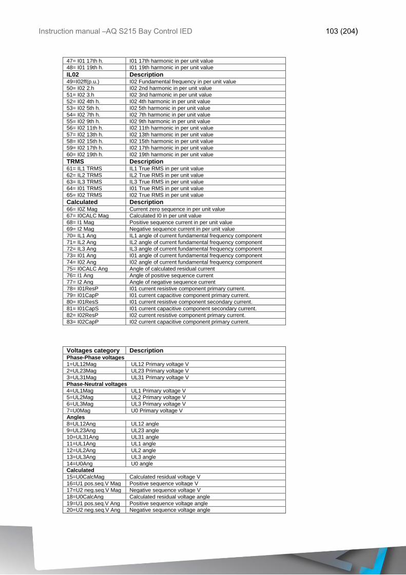
Instruction manual –AQ S215 Bay Control IED 103 (204)
47= I01 17th h. I01 17th harmonic in per unit value
48= I01 19th h. I01 19th harmonic in per unit value
IL02 Description 49=I02ff(p.u.) I02 Fundamental frequency in per unit value 50= I02 2.h I02 2nd harmonic in per unit value
51= I02 3.h I02 3nd harmonic in per unit value
52= I02 4th h. I02 4th harmonic in per unit value
53= I02 5th h. I02 5th harmonic in per unit value
54= I02 7th h. I02 7th harmonic in per unit value
55= I02 9th h. I02 9th harmonic in per unit value
56= I02 11th h. I02 11th harmonic in per unit value
57= I02 13th h. I02 13th harmonic in per unit value
58= I02 15th h. I02 15th harmonic in per unit value
59= I02 17th h. I02 17th harmonic in per unit value
60= I02 19th h. I02 19th harmonic in per unit value
TRMS Description 61= IL1 TRMS IL1 True RMS in per unit value 62= IL2 TRMS IL2 True RMS in per unit value
63= IL3 TRMS IL3 True RMS in per unit value
64= I01 TRMS I01 True RMS in per unit value
65= I02 TRMS I02 True RMS in per unit value
Calculated Description 66= I0Z Mag Current zero sequence in per unit value
67= I0CALC Mag Calculated I0 in per unit value
68= I1 Mag Positive sequence current in per unit value
69= I2 Mag Negative sequence current in per unit value
70= IL1 Ang IL1 angle of current fundamental frequency component
71= IL2 Ang IL2 angle of current fundamental frequency component
72= IL3 Ang IL3 angle of current fundamental frequency component
73= I01 Ang I01 angle of current fundamental frequency component 74= I02 Ang I02 angle of current fundamental frequency component
75= I0CALC Ang Angle of calculated residual current
76= I1 Ang Angle of positive sequence current
77= I2 Ang Angle of negative sequence current
78= I01ResP I01 current resistive component primary current.
79= I01CapP I01 current capacitive component primary current.
80= I01ResS I01 current resistive component secondary current.
81= I01CapS I01 current capacitive component secondary current.
82= I02ResP I02 current resistive component primary current.
83= I02CapP I02 current capacitive component primary current.
Voltages category Description Phase-Phase voltages
1=UL12Mag UL12 Primary voltage V
2=UL23Mag UL23 Primary voltage V
3=UL31Mag UL31 Primary voltage V
Phase-Neutral voltages
4=UL1Mag UL1 Primary voltage V
5=UL2Mag UL2 Primary voltage V
6=UL3Mag UL3 Primary voltage V
7=U0Mag U0 Primary voltage V
Angles
8=UL12Ang UL12 angle
9=UL23Ang UL23 angle
10=UL31Ang UL31 angle
11=UL1Ang UL1 angle
12=UL2Ang UL2 angle
13=UL3Ang UL3 angle
14=U0Ang U0 angle
Calculated
15=U0CalcMag Calculated residual voltage V
16=U1 pos.seq.V Mag Positive sequence voltage V
17=U2 neg.seq.V Mag Negative sequence voltage V
18=U0CalcAng Calculated residual voltage angle
19=U1 pos.seq.V Ang Positive sequence voltage angle
20=U2 neg.seq.V Ang Negative sequence voltage angle
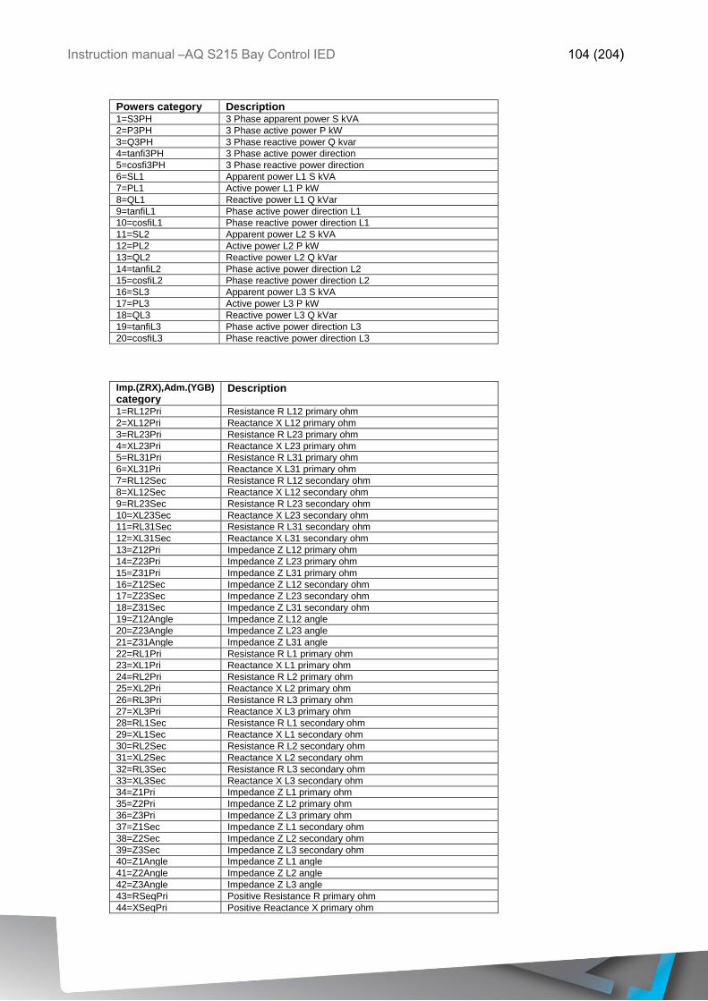
Instruction manual –AQ S215 Bay Control IED 104 (204)
Powers category Description 1=S3PH 3 Phase apparent power S kVA
2=P3PH 3 Phase active power P kW
3=Q3PH 3 Phase reactive power Q kvar
4=tanfi3PH 3 Phase active power direction
5=cosfi3PH 3 Phase reactive power direction
6=SL1 Apparent power L1 S kVA
7=PL1 Active power L1 P kW
8=QL1 Reactive power L1 Q kVar
9=tanfiL1 Phase active power direction L1
10=cosfiL1 Phase reactive power direction L1
11=SL2 Apparent power L2 S kVA
12=PL2 Active power L2 P kW
13=QL2 Reactive power L2 Q kVar
14=tanfiL2 Phase active power direction L2
15=cosfiL2 Phase reactive power direction L2
16=SL3 Apparent power L3 S kVA
17=PL3 Active power L3 P kW
18=QL3 Reactive power L3 Q kVar
19=tanfiL3 Phase active power direction L3
20=cosfiL3 Phase reactive power direction L3
Imp.(ZRX),Adm.(YGB)
category Description
1=RL12Pri Resistance R L12 primary ohm
2=XL12Pri Reactance X L12 primary ohm
3=RL23Pri Resistance R L23 primary ohm
4=XL23Pri Reactance X L23 primary ohm
5=RL31Pri Resistance R L31 primary ohm
6=XL31Pri Reactance X L31 primary ohm
7=RL12Sec Resistance R L12 secondary ohm
8=XL12Sec Reactance X L12 secondary ohm
9=RL23Sec Resistance R L23 secondary ohm
10=XL23Sec Reactance X L23 secondary ohm
11=RL31Sec Resistance R L31 secondary ohm
12=XL31Sec Reactance X L31 secondary ohm
13=Z12Pri Impedance Z L12 primary ohm
14=Z23Pri Impedance Z L23 primary ohm
15=Z31Pri Impedance Z L31 primary ohm
16=Z12Sec Impedance Z L12 secondary ohm
17=Z23Sec Impedance Z L23 secondary ohm
18=Z31Sec Impedance Z L31 secondary ohm
19=Z12Angle Impedance Z L12 angle
20=Z23Angle Impedance Z L23 angle
21=Z31Angle Impedance Z L31 angle
22=RL1Pri Resistance R L1 primary ohm
23=XL1Pri Reactance X L1 primary ohm
24=RL2Pri Resistance R L2 primary ohm
25=XL2Pri Reactance X L2 primary ohm
26=RL3Pri Resistance R L3 primary ohm
27=XL3Pri Reactance X L3 primary ohm
28=RL1Sec Resistance R L1 secondary ohm
29=XL1Sec Reactance X L1 secondary ohm
30=RL2Sec Resistance R L2 secondary ohm
31=XL2Sec Reactance X L2 secondary ohm
32=RL3Sec Resistance R L3 secondary ohm
33=XL3Sec Reactance X L3 secondary ohm
34=Z1Pri Impedance Z L1 primary ohm
35=Z2Pri Impedance Z L2 primary ohm
36=Z3Pri Impedance Z L3 primary ohm
37=Z1Sec Impedance Z L1 secondary ohm
38=Z2Sec Impedance Z L2 secondary ohm
39=Z3Sec Impedance Z L3 secondary ohm
40=Z1Angle Impedance Z L1 angle
41=Z2Angle Impedance Z L2 angle
42=Z3Angle Impedance Z L3 angle
43=RSeqPri Positive Resistance R primary ohm
44=XSeqPri Positive Reactance X primary ohm
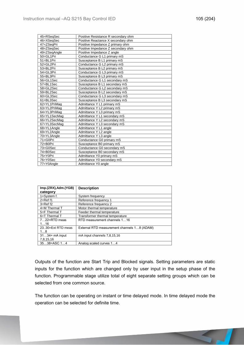
Instruction manual –AQ S215 Bay Control IED 105 (204)
45=RSeqSec Positive Resistance R secondary ohm
46=XSeqSec Positive Reactance X secondary ohm
47=ZSeqPri Positive Impedance Z primary ohm
48=ZSeqSec Positive Impedance Z secondary ohm
49=ZSeqAngle Positive Impedance Z angle
50=GL1Pri Conductance G L1 primary mS
51=BL1Pri Susceptance B L1 primary mS
52=GL2Pri Conductance G L2 primary mS
53=BL2Pri Susceptance B L2 primary mS
54=GL3Pri Conductance G L3 primary mS
55=BL3Pri Susceptance B L3 primary mS
56=GL1Sec Conductance G L1 secondary mS
57=BL1Sec Susceptance B L1 secondary mS
58=GL2Sec Conductance G L2 secondary mS
59=BL2Sec Susceptance B L2 secondary mS
60=GL3Sec Conductance G L3 secondary mS
61=BL3Sec Susceptance B L3 secondary mS
62=YL1PriMag Admittance Y L1 primary mS
63=YL2PriMag Admittance Y L2 primary mS
64=YL3PriMag Admittance Y L3 primary mS
65=YL1SecMag Admittance Y L1 secondary mS
66=YL2SecMag Admittance Y L2 secondary mS
67=YL3SecMag Admittance Y L3 secondary mS
68=YL1Angle Admittance Y L1 angle
69=YL2Angle Admittance Y L2 angle
70=YL3Angle Admittance Y L3 angle
71=G0Pri Conductance G0 primary mS
72=B0Pri Susceptance B0 primary mS
73=G0Sec Conductance G0 secondary mS
74=B0Sec Susceptance B0 secondary mS
75=Y0Pri Admittance Y0 primary mS
76=Y0Sec Admittance Y0 secondary mS
77=Y0Angle Admittance Y0 angle
Imp.(ZRX),Adm.(YGB)
category Description
1=System f. System frequency
2=Ref f1 Reference frequency 1
3=Ref f2 Reference frequency 2
4=M Thermal T Motor thermal temperature
5=F Thermal T Feeder thermal temperature
6=T Thermal T Transformer thermal temperature
7…22=RTD meas 1…16
RTD measurement channels 1…16
23..30=Ext RTD meas 1…8
External RTD measurement channels 1…8 (ADAM)
31…34= mA input 7,8,15,16
mA input channels 7,8,15,16
35…38=ASC 1…4 Analog scaled curves 1…4
Outputs of the function are Start Trip and Blocked signals. Setting parameters are static
inputs for the function which are changed only by user input in the setup phase of the
function. Programmable stage utilize total of eight separate setting groups which can be
selected from one common source.
The function can be operating on instant or time delayed mode. In time delayed mode the
operation can be selected for definite time.

Instruction manual –AQ S215 Bay Control IED 106 (204)
Inputs for the function are the operating mode selections, setting parameters and measured
and pre-processed magnitudes and binary input signals. Function outputs START, TRIP
and BLOCKED signals which can be used for direct IO controlling and also for user logic
programming. The function registers its operation into 12 last time-stamped registers and
also generates general time stamped ON/OFF events to the common event buffer from
each of the three output signal. In instant operating mode the function outputs START and
TRIP events simultaneously with equivalent time stamp. Time stamp resolution is 1ms.
Function provides also cumulative counters for START, TRIP and BLOCKED events.
4.1.9.3 PICK-UP CHARACTERISTICS
Pick-up of the PGS function is controlled by Pick-up setting Mag setting parameter, which
defines the maximum/minimum allowed measured magnitude before action from the
function. The function constantly calculates the ratio in between the set and measured
magnitude. Reset hysteresis is user settable (3% by default) in the function and is always
related to the Pick-up setting Mag value.
Table 4-34 Pick-up characteristics setting
Name Description Range Step Default
PS# Pick-up setting Mag#/calc
>/<
Pick-up
magnitude
-5000000.0000…5000000.0000 0.0001 0.01
PS# Setting hysteresis Mag# Setting
hysteresis
0.0000…50.0000% 0.0001% 3%
Definite operating time delay Delay setting 0.000…1800.000s 0.005s 0.04s
Release time delays Pick-up
release delay
0.000…1800.000s 0.005s 0.06s
The pick-up activation of the function is not directly equal to start-signal generation of the
function. Start signal is allowed if blocking condition is not active.
Resetting characteristics can be set according to the application. Default setting is delayed
with 60 ms and the time calculation is held during the release time.
When using the release delay option where the operating time counter is calculating the
operating time during the release time, function will not trip if the input signal is not activated
again during the release time counting.
4.1.9.4 FUNCTION BLOCKING
In the blocking element the block signal is checked in the beginning of each program cycle.
Blocking signal is received from the blocking matrix for the function dedicated input. If the
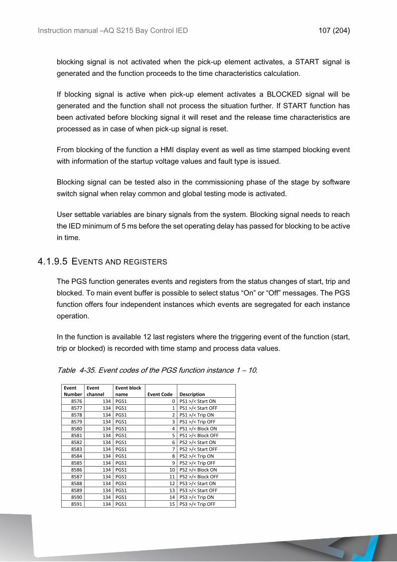
Instruction manual –AQ S215 Bay Control IED 107 (204)
blocking signal is not activated when the pick-up element activates, a START signal is
generated and the function proceeds to the time characteristics calculation.
If blocking signal is active when pick-up element activates a BLOCKED signal will be
generated and the function shall not process the situation further. If START function has
been activated before blocking signal it will reset and the release time characteristics are
processed as in case of when pick-up signal is reset.
From blocking of the function a HMI display event as well as time stamped blocking event
with information of the startup voltage values and fault type is issued.
Blocking signal can be tested also in the commissioning phase of the stage by software
switch signal when relay common and global testing mode is activated.
User settable variables are binary signals from the system. Blocking signal needs to reach
the IED minimum of 5 ms before the set operating delay has passed for blocking to be active
in time.
4.1.9.5 EVENTS AND REGISTERS
The PGS function generates events and registers from the status changes of start, trip and
blocked. To main event buffer is possible to select status “On” or “Off” messages. The PGS
function offers four independent instances which events are segregated for each instance
operation.
In the function is available 12 last registers where the triggering event of the function (start,
trip or blocked) is recorded with time stamp and process data values.
Table 4-35. Event codes of the PGS function instance 1 – 10.
Event Number
Event channel
Event block name Event Code Description
8576 134 PGS1 0 PS1 >/< Start ON
8577 134 PGS1 1 PS1 >/< Start OFF
8578 134 PGS1 2 PS1 >/< Trip ON
8579 134 PGS1 3 PS1 >/< Trip OFF
8580 134 PGS1 4 PS1 >/< Block ON
8581 134 PGS1 5 PS1 >/< Block OFF
8582 134 PGS1 6 PS2 >/< Start ON
8583 134 PGS1 7 PS2 >/< Start OFF
8584 134 PGS1 8 PS2 >/< Trip ON
8585 134 PGS1 9 PS2 >/< Trip OFF
8586 134 PGS1 10 PS2 >/< Block ON
8587 134 PGS1 11 PS2 >/< Block OFF
8588 134 PGS1 12 PS3 >/< Start ON
8589 134 PGS1 13 PS3 >/< Start OFF
8590 134 PGS1 14 PS3 >/< Trip ON
8591 134 PGS1 15 PS3 >/< Trip OFF
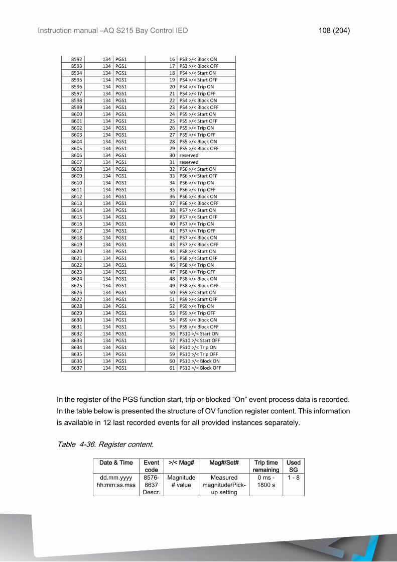
Instruction manual –AQ S215 Bay Control IED 108 (204)
8592 134 PGS1 16 PS3 >/< Block ON
8593 134 PGS1 17 PS3 >/< Block OFF
8594 134 PGS1 18 PS4 >/< Start ON
8595 134 PGS1 19 PS4 >/< Start OFF
8596 134 PGS1 20 PS4 >/< Trip ON
8597 134 PGS1 21 PS4 >/< Trip OFF
8598 134 PGS1 22 PS4 >/< Block ON
8599 134 PGS1 23 PS4 >/< Block OFF
8600 134 PGS1 24 PS5 >/< Start ON
8601 134 PGS1 25 PS5 >/< Start OFF
8602 134 PGS1 26 PS5 >/< Trip ON
8603 134 PGS1 27 PS5 >/< Trip OFF
8604 134 PGS1 28 PS5 >/< Block ON
8605 134 PGS1 29 PS5 >/< Block OFF
8606 134 PGS1 30 reserved
8607 134 PGS1 31 reserved
8608 134 PGS1 32 PS6 >/< Start ON
8609 134 PGS1 33 PS6 >/< Start OFF
8610 134 PGS1 34 PS6 >/< Trip ON
8611 134 PGS1 35 PS6 >/< Trip OFF
8612 134 PGS1 36 PS6 >/< Block ON
8613 134 PGS1 37 PS6 >/< Block OFF
8614 134 PGS1 38 PS7 >/< Start ON
8615 134 PGS1 39 PS7 >/< Start OFF
8616 134 PGS1 40 PS7 >/< Trip ON
8617 134 PGS1 41 PS7 >/< Trip OFF
8618 134 PGS1 42 PS7 >/< Block ON
8619 134 PGS1 43 PS7 >/< Block OFF
8620 134 PGS1 44 PS8 >/< Start ON
8621 134 PGS1 45 PS8 >/< Start OFF
8622 134 PGS1 46 PS8 >/< Trip ON
8623 134 PGS1 47 PS8 >/< Trip OFF
8624 134 PGS1 48 PS8 >/< Block ON
8625 134 PGS1 49 PS8 >/< Block OFF
8626 134 PGS1 50 PS9 >/< Start ON
8627 134 PGS1 51 PS9 >/< Start OFF
8628 134 PGS1 52 PS9 >/< Trip ON
8629 134 PGS1 53 PS9 >/< Trip OFF
8630 134 PGS1 54 PS9 >/< Block ON
8631 134 PGS1 55 PS9 >/< Block OFF
8632 134 PGS1 56 PS10 >/< Start ON
8633 134 PGS1 57 PS10 >/< Start OFF
8634 134 PGS1 58 PS10 >/< Trip ON
8635 134 PGS1 59 PS10 >/< Trip OFF
8636 134 PGS1 60 PS10 >/< Block ON
8637 134 PGS1 61 PS10 >/< Block OFF
In the register of the PGS function start, trip or blocked “On” event process data is recorded.
In the table below is presented the structure of OV function register content. This information
is available in 12 last recorded events for all provided instances separately.
Table 4-36. Register content.
Date & Time Event
code
>/< Mag# Mag#/Set# Trip time
remaining
Used
SG
dd.mm.yyyy
hh:mm:ss.mss
8576-
8637
Descr.
Magnitude
# value
Measured
magnitude/Pick-
up setting
0 ms -
1800 s
1 - 8

Instruction manual –AQ S215 Bay Control IED 109 (204)
4.2 MONITORING FUNCTIONS
4.2.1 CURRENT TRANSFORMER SUPERVISION
Current transformer supervision (CTS) function is meant to be used for monitoring the CT:s,
wirings in between of the IED and IED CT inputs in case of malfunction or wire breaks.
Open CT circuit can generate dangerously high voltages into the CT secondary side as well
as cause not intended activation of current balance monitoring functions.
CTS function constantly monitors phase current instant values as well as key calculated
magnitudes of the phase currents. Also residual current circuit can be monitored if the
residual current is measured from dedicated residual current CT. Residual circuit monitoring
can be enabled or disabled by user selection.
Blocking signal and setting group selection controls the operating characteristics of the
function during normal operation.
Outputs of the function are CTS alarm and Blocked signals. Setting parameters are static
inputs for the function which are changed only by user input in the setup phase of the
function. CTS function utilizes total of eight separate setting groups which can be selected
from one common source. Also the operating mode of the CTS can be changed by setting
group selection.
The operational logic consists of input magnitude processing, threshold comparator, block
signal check, time delay characteristics and output processing.
For the CTS function alarm activation following conditions has to be met simultaneously:
- None of the three phase currents is over the set Iset Highlimit setting
- At least one of the three phase currents is over the Iset Lowlimit setting
- At least one of the three phase currents is under the Iset Lowlimit setting
- Three phase current calculated Min/Max ratio is under the Iset ratio setting
- Negative sequence / Positive sequence ratio is over the I2/I1 ratio setting
- Calculated (IL1̅̅ ̅̅ + IL2̅̅ ̅̅ + IL3̅̅ ̅̅ + I0̅) difference is over the Isum difference setting (optional)
- Above mentioned condition is met until the set TCTS time
Inputs for the function are setting parameters and measured and pre-processed current
magnitudes. Function output signals can be used for direct IO controlling and also for user
logic programming. The function registers its operation into 12 last time-stamped registers
and also generates general time stamped ON/OFF events to the common event buffer from
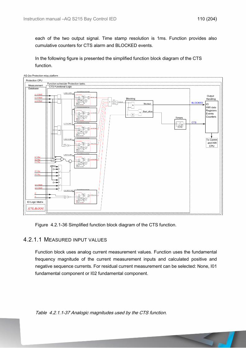
Instruction manual –AQ S215 Bay Control IED 110 (204)
each of the two output signal. Time stamp resolution is 1ms. Function provides also
cumulative counters for CTS alarm and BLOCKED events.
In the following figure is presented the simplified function block diagram of the CTS
function.
Figure 4.2.1-36 Simplified function block diagram of the CTS function.
4.2.1.1 MEASURED INPUT VALUES
Function block uses analog current measurement values. Function uses the fundamental
frequency magnitude of the current measurement inputs and calculated positive and
negative sequence currents. For residual current measurement can be selected: None, I01
fundamental component or I02 fundamental component.
Table 4.2.1.1-37 Analogic magnitudes used by the CTS function.
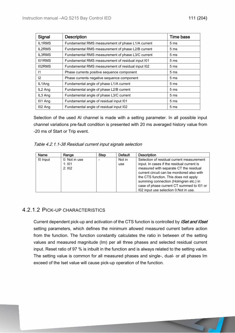
Instruction manual –AQ S215 Bay Control IED 111 (204)
Signal Description Time base
IL1RMS Fundamental RMS measurement of phase L1/A current 5 ms
IL2RMS Fundamental RMS measurement of phase L2/B current 5 ms
IL3RMS Fundamental RMS measurement of phase L3/C current 5 ms
I01RMS Fundamental RMS measurement of residual input I01 5 ms
I02RMS Fundamental RMS measurement of residual input I02 5 ms
I1 Phase currents positive sequence component 5 ms
I2 Phase currents negative sequence component 5 ms
IL1Ang Fundamental angle of phase L1/A current 5 ms
IL2 Ang Fundamental angle of phase L2/B current 5 ms
IL3 Ang Fundamental angle of phase L3/C current 5 ms
I01 Ang Fundamental angle of residual input I01 5 ms
I02 Ang Fundamental angle of residual input I02 5 ms
Selection of the used AI channel is made with a setting parameter. In all possible input
channel variations pre-fault condition is presented with 20 ms averaged history value from
-20 ms of Start or Trip event.
Table 4.2.1.1-38 Residual current input signals selection
Name Range Step Default Description
I0 Input 0: Not in use
1: I01
2: I02
- Not in
use
Selection of residual current measurement
input. In cases if the residual current is
measured with separate CT the residual
current circuit can be monitored also with
the CTS function. This does not apply
summing connection (Holmgren etc.) in
case of phase current CT summed to I01 or
I02 input use selection 0:Not in use.
4.2.1.2 PICK-UP CHARACTERISTICS
Current dependent pick-up and activation of the CTS function is controlled by ISet and I0set
setting parameters, which defines the minimum allowed measured current before action
from the function. The function constantly calculates the ratio in between of the setting
values and measured magnitude (Im) per all three phases and selected residual current
input. Reset ratio of 97 % is inbuilt in the function and is always related to the setting value.
The setting value is common for all measured phases and single-, dual- or all phases Im
exceed of the Iset value will cause pick-up operation of the function.
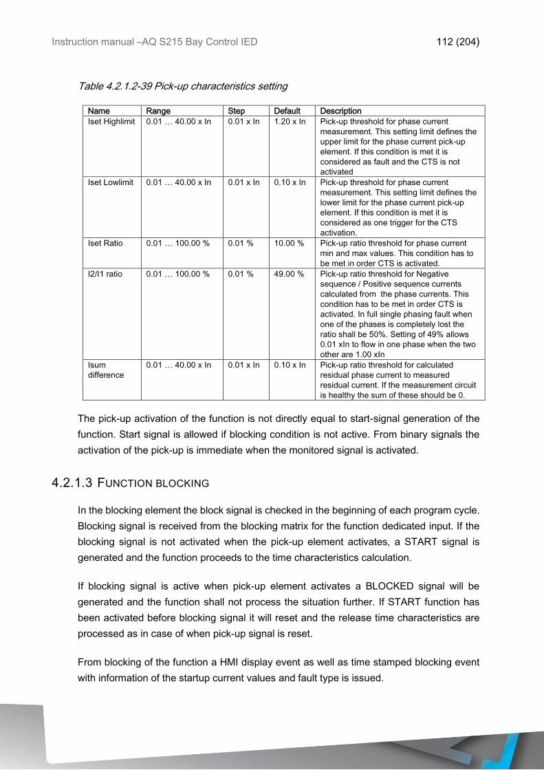
Instruction manual –AQ S215 Bay Control IED 112 (204)
Table 4.2.1.2-39 Pick-up characteristics setting
Name Range Step Default Description
Iset Highlimit 0.01 … 40.00 x In 0.01 x In 1.20 x In Pick-up threshold for phase current
measurement. This setting limit defines the
upper limit for the phase current pick-up
element. If this condition is met it is
considered as fault and the CTS is not
activated
Iset Lowlimit 0.01 … 40.00 x In 0.01 x In 0.10 x In Pick-up threshold for phase current
measurement. This setting limit defines the
lower limit for the phase current pick-up
element. If this condition is met it is
considered as one trigger for the CTS
activation.
Iset Ratio 0.01 … 100.00 % 0.01 % 10.00 % Pick-up ratio threshold for phase current
min and max values. This condition has to
be met in order CTS is activated.
I2/I1 ratio 0.01 … 100.00 % 0.01 % 49.00 % Pick-up ratio threshold for Negative
sequence / Positive sequence currents
calculated from the phase currents. This
condition has to be met in order CTS is
activated. In full single phasing fault when
one of the phases is completely lost the
ratio shall be 50%. Setting of 49% allows
0.01 xIn to flow in one phase when the two
other are 1.00 xIn
Isum
difference
0.01 … 40.00 x In 0.01 x In 0.10 x In Pick-up ratio threshold for calculated
residual phase current to measured
residual current. If the measurement circuit
is healthy the sum of these should be 0.
The pick-up activation of the function is not directly equal to start-signal generation of the
function. Start signal is allowed if blocking condition is not active. From binary signals the
activation of the pick-up is immediate when the monitored signal is activated.
4.2.1.3 FUNCTION BLOCKING
In the blocking element the block signal is checked in the beginning of each program cycle.
Blocking signal is received from the blocking matrix for the function dedicated input. If the
blocking signal is not activated when the pick-up element activates, a START signal is
generated and the function proceeds to the time characteristics calculation.
If blocking signal is active when pick-up element activates a BLOCKED signal will be
generated and the function shall not process the situation further. If START function has
been activated before blocking signal it will reset and the release time characteristics are
processed as in case of when pick-up signal is reset.
From blocking of the function a HMI display event as well as time stamped blocking event
with information of the startup current values and fault type is issued.
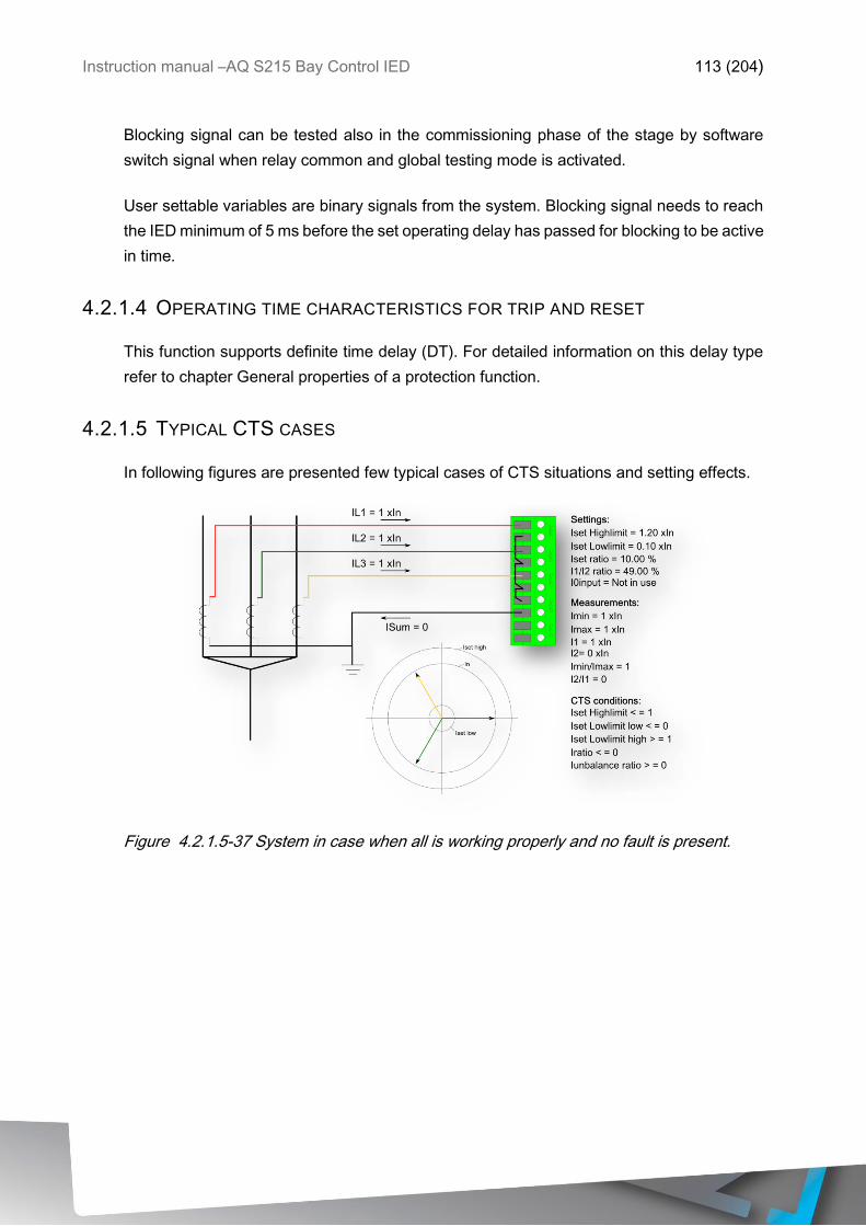
Instruction manual –AQ S215 Bay Control IED 113 (204)
Blocking signal can be tested also in the commissioning phase of the stage by software
switch signal when relay common and global testing mode is activated.
User settable variables are binary signals from the system. Blocking signal needs to reach
the IED minimum of 5 ms before the set operating delay has passed for blocking to be active
in time.
4.2.1.4 OPERATING TIME CHARACTERISTICS FOR TRIP AND RESET
This function supports definite time delay (DT). For detailed information on this delay type
refer to chapter General properties of a protection function.
4.2.1.5 TYPICAL CTS CASES
In following figures are presented few typical cases of CTS situations and setting effects.
Figure 4.2.1.5-37 System in case when all is working properly and no fault is present.
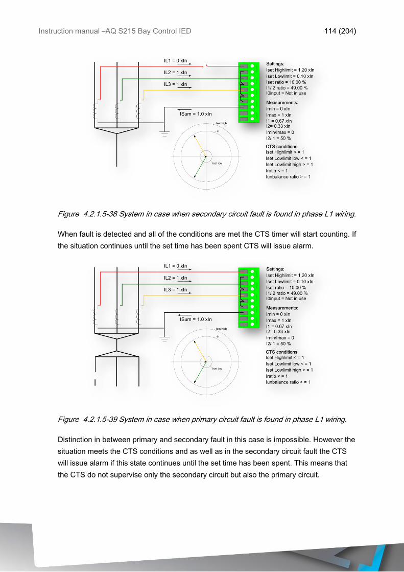
Instruction manual –AQ S215 Bay Control IED 114 (204)
Figure 4.2.1.5-38 System in case when secondary circuit fault is found in phase L1 wiring.
When fault is detected and all of the conditions are met the CTS timer will start counting. If
the situation continues until the set time has been spent CTS will issue alarm.
Figure 4.2.1.5-39 System in case when primary circuit fault is found in phase L1 wiring.
Distinction in between primary and secondary fault in this case is impossible. However the
situation meets the CTS conditions and as well as in the secondary circuit fault the CTS
will issue alarm if this state continues until the set time has been spent. This means that
the CTS do not supervise only the secondary circuit but also the primary circuit.
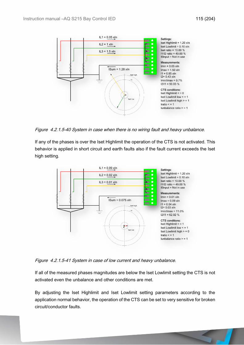
Instruction manual –AQ S215 Bay Control IED 115 (204)
Figure 4.2.1.5-40 System in case when there is no wiring fault and heavy unbalance.
If any of the phases is over the Iset Highlimit the operation of the CTS is not activated. This
behavior is applied in short circuit and earth faults also if the fault current exceeds the Iset
high setting.
Figure 4.2.1.5-41 System in case of low current and heavy unbalance.
If all of the measured phases magnitudes are below the Iset Lowlimit setting the CTS is not
activated even the unbalance and other conditions are met.
By adjusting the Iset Highlimit and Iset Lowlimit setting parameters according to the
application normal behavior, the operation of the CTS can be set to very sensitive for broken
circuit/conductor faults.
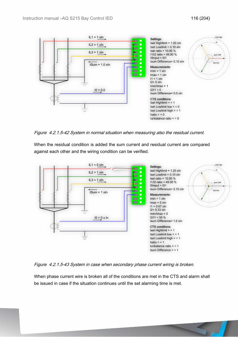
Instruction manual –AQ S215 Bay Control IED 116 (204)
Figure 4.2.1.5-42 System in normal situation when measuring also the residual current.
When the residual condition is added the sum current and residual current are compared
against each other and the wiring condition can be verified.
Figure 4.2.1.5-43 System in case when secondary phase current wiring is broken.
When phase current wire is broken all of the conditions are met in the CTS and alarm shall
be issued in case if the situation continues until the set alarming time is met.
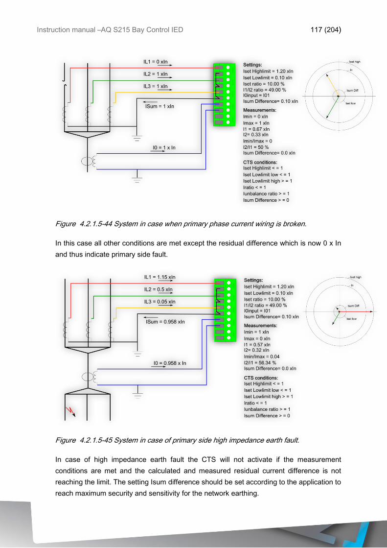
Instruction manual –AQ S215 Bay Control IED 117 (204)
Figure 4.2.1.5-44 System in case when primary phase current wiring is broken.
In this case all other conditions are met except the residual difference which is now 0 x In
and thus indicate primary side fault.
Figure 4.2.1.5-45 System in case of primary side high impedance earth fault.
In case of high impedance earth fault the CTS will not activate if the measurement
conditions are met and the calculated and measured residual current difference is not
reaching the limit. The setting Isum difference should be set according to the application to
reach maximum security and sensitivity for the network earthing.
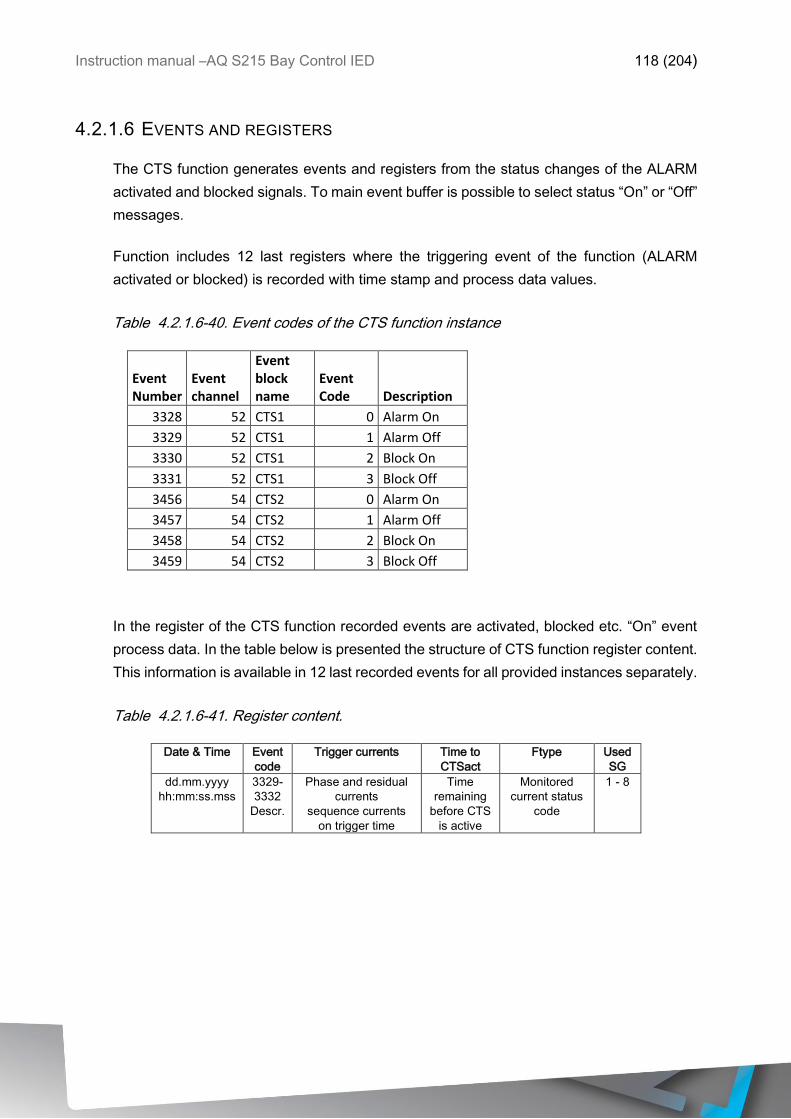
Instruction manual –AQ S215 Bay Control IED 118 (204)
4.2.1.6 EVENTS AND REGISTERS
The CTS function generates events and registers from the status changes of the ALARM
activated and blocked signals. To main event buffer is possible to select status “On” or “Off”
messages.
Function includes 12 last registers where the triggering event of the function (ALARM
activated or blocked) is recorded with time stamp and process data values.
Table 4.2.1.6-40. Event codes of the CTS function instance
Event Number
Event channel
Event block name
Event Code Description
3328 52 CTS1 0 Alarm On
3329 52 CTS1 1 Alarm Off
3330 52 CTS1 2 Block On
3331 52 CTS1 3 Block Off
3456 54 CTS2 0 Alarm On
3457 54 CTS2 1 Alarm Off
3458 54 CTS2 2 Block On
3459 54 CTS2 3 Block Off
In the register of the CTS function recorded events are activated, blocked etc. “On” event
process data. In the table below is presented the structure of CTS function register content.
This information is available in 12 last recorded events for all provided instances separately.
Table 4.2.1.6-41. Register content.
Date & Time Event
code
Trigger currents Time to
CTSact
Ftype Used
SG
dd.mm.yyyy
hh:mm:ss.mss
3329-
3332
Descr.
Phase and residual
currents
sequence currents
on trigger time
Time
remaining
before CTS
is active
Monitored
current status
code
1 - 8
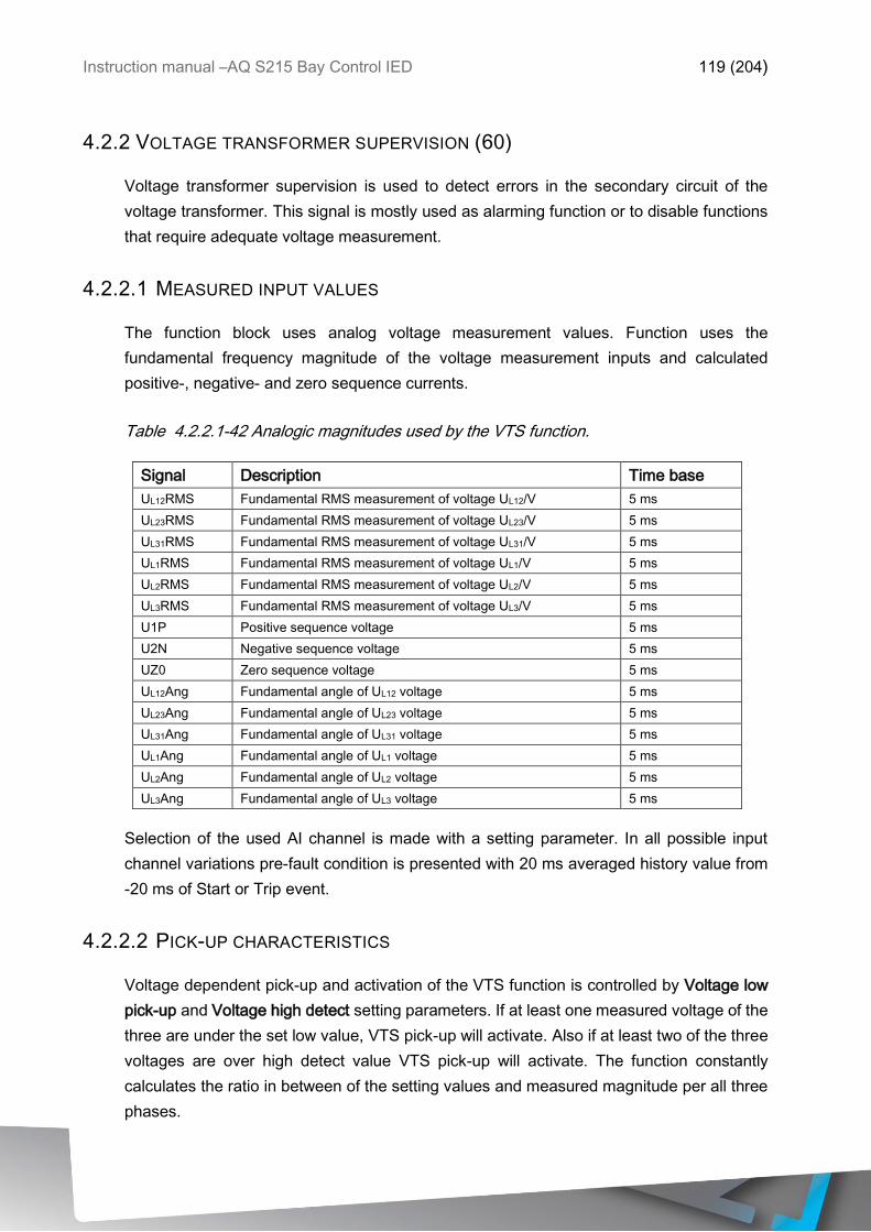
Instruction manual –AQ S215 Bay Control IED 119 (204)
4.2.2 VOLTAGE TRANSFORMER SUPERVISION (60)
Voltage transformer supervision is used to detect errors in the secondary circuit of the
voltage transformer. This signal is mostly used as alarming function or to disable functions
that require adequate voltage measurement.
4.2.2.1 MEASURED INPUT VALUES
The function block uses analog voltage measurement values. Function uses the
fundamental frequency magnitude of the voltage measurement inputs and calculated
positive-, negative- and zero sequence currents.
Table 4.2.2.1-42 Analogic magnitudes used by the VTS function.
Signal Description Time base
UL12RMS Fundamental RMS measurement of voltage UL12/V 5 ms
UL23RMS Fundamental RMS measurement of voltage UL23/V 5 ms
UL31RMS Fundamental RMS measurement of voltage UL31/V 5 ms
UL1RMS Fundamental RMS measurement of voltage UL1/V 5 ms
UL2RMS Fundamental RMS measurement of voltage UL2/V 5 ms
UL3RMS Fundamental RMS measurement of voltage UL3/V 5 ms
U1P Positive sequence voltage 5 ms
U2N Negative sequence voltage 5 ms
UZ0 Zero sequence voltage 5 ms
UL12Ang Fundamental angle of UL12 voltage 5 ms
UL23Ang Fundamental angle of UL23 voltage 5 ms
UL31Ang Fundamental angle of UL31 voltage 5 ms
UL1Ang Fundamental angle of UL1 voltage 5 ms
UL2Ang Fundamental angle of UL2 voltage 5 ms
UL3Ang Fundamental angle of UL3 voltage 5 ms
Selection of the used AI channel is made with a setting parameter. In all possible input
channel variations pre-fault condition is presented with 20 ms averaged history value from
-20 ms of Start or Trip event.
4.2.2.2 PICK-UP CHARACTERISTICS
Voltage dependent pick-up and activation of the VTS function is controlled by Voltage low
pick-up and Voltage high detect setting parameters. If at least one measured voltage of the
three are under the set low value, VTS pick-up will activate. Also if at least two of the three
voltages are over high detect value VTS pick-up will activate. The function constantly
calculates the ratio in between of the setting values and measured magnitude per all three
phases.

Instruction manual –AQ S215 Bay Control IED 120 (204)
Table 4.2.2.2-43 Pick-up characteristics setting
Name Range Step Default Description
Voltage low
pickup
0.00 … 0.50 x Un 0.01 x Un 0.05 x Un If at least one of the measured voltages are
under this set value the function will pick up
Voltage high
detect
0.01 … 40.00 x In 0.01 x In 0.10 x In If at least two of the measured voltages are
over this set value the function will pick up
Angle shift
limit
2.00 … 90.00 deg 0.10 deg 5.00 deg If the difference between the angle in
present time and -40ms before is lower
than the set value function will pick up
Line Fuse
fail check
No
Yes
- Yes Selection if the state of the line fuse will be
supervised. The supervised signal is
determined in IO Fuse-Failure Inputs
Bus Fuse fail
check
No
Yes
- Yes Selection if the state of the bus fuse will be
supervised. The supervised signal is
determined in IO Fuse-Failure Inputs
The pick-up activation of the function is not directly equal to start-signal generation of the
function. Start signal is allowed if blocking condition is not active. From binary signals the
activation of the pick-up is immediate when the monitored signal is activated.
Voltage transformer supervision can also report several different states of the measured
voltage. These can be seen in the INFO-page of the function in the relay HMI or in AQtivate.
Name Description
Bus dead No voltages
Bus Live VTS Ok All of the voltages are within the
set limits
Bus Live VTS Ok SEQ
Rev
All of the voltages are within the
set limits BUT the voltages are
in reversed sequence
Bus Live VTS Ok SEQ
Undef
Voltages are within the set limits
BUT sequence cannot be
defined.
Bus Live VTS problem Any of the VTS pick-up
conditions are valid!
4.2.2.3 FUNCTION BLOCKING
In the blocking element the block signal is checked in the beginning of each program cycle.
Blocking signal is received from the blocking matrix for the function dedicated input. If the
blocking signal is not activated when the pick-up element activates, a START signal is
generated and the function proceeds to the time characteristics calculation.
If blocking signal is active when pick-up element activates a BLOCKED signal will be
generated and the function shall not process the situation further. If START function has
been activated before blocking signal it will reset and the release time characteristics are
processed as in case of when pick-up signal is reset.
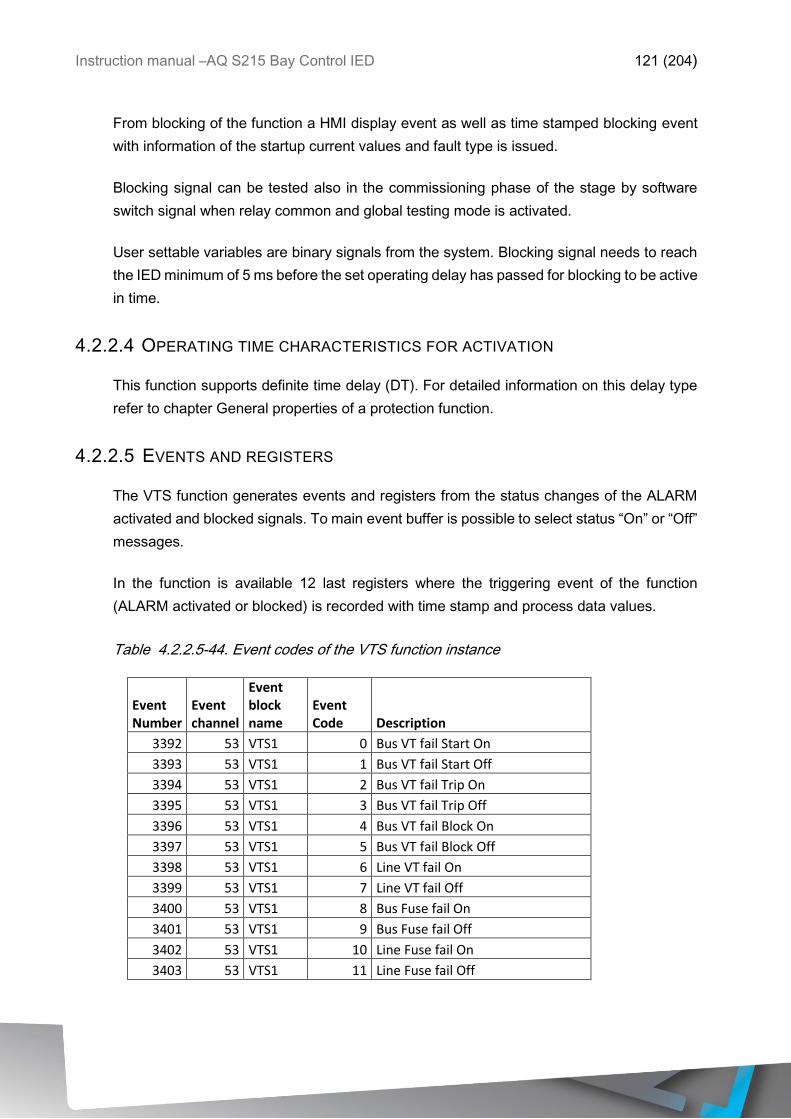
Instruction manual –AQ S215 Bay Control IED 121 (204)
From blocking of the function a HMI display event as well as time stamped blocking event
with information of the startup current values and fault type is issued.
Blocking signal can be tested also in the commissioning phase of the stage by software
switch signal when relay common and global testing mode is activated.
User settable variables are binary signals from the system. Blocking signal needs to reach
the IED minimum of 5 ms before the set operating delay has passed for blocking to be active
in time.
4.2.2.4 OPERATING TIME CHARACTERISTICS FOR ACTIVATION
This function supports definite time delay (DT). For detailed information on this delay type
refer to chapter General properties of a protection function.
4.2.2.5 EVENTS AND REGISTERS
The VTS function generates events and registers from the status changes of the ALARM
activated and blocked signals. To main event buffer is possible to select status “On” or “Off”
messages.
In the function is available 12 last registers where the triggering event of the function
(ALARM activated or blocked) is recorded with time stamp and process data values.
Table 4.2.2.5-44. Event codes of the VTS function instance
Event Number
Event channel
Event block name
Event Code Description
3392 53 VTS1 0 Bus VT fail Start On
3393 53 VTS1 1 Bus VT fail Start Off
3394 53 VTS1 2 Bus VT fail Trip On
3395 53 VTS1 3 Bus VT fail Trip Off
3396 53 VTS1 4 Bus VT fail Block On
3397 53 VTS1 5 Bus VT fail Block Off
3398 53 VTS1 6 Line VT fail On
3399 53 VTS1 7 Line VT fail Off
3400 53 VTS1 8 Bus Fuse fail On
3401 53 VTS1 9 Bus Fuse fail Off
3402 53 VTS1 10 Line Fuse fail On
3403 53 VTS1 11 Line Fuse fail Off

Instruction manual –AQ S215 Bay Control IED 122 (204)
In the register of the VTS function is recorded activated, blocked etc. “On” event process
data. In the table below is presented the structure of VTS function register content. This
information is available in 12 last recorded events for all provided instances separately.
Table 4.2.2.5-45. Register content.
Date & Time Event
code
Volt 1,2,3 status System status Input
A,B,C
angle diff
Trip time
remaining
Used
SG
dd.mm.yyyy
hh:mm:ss.mss
3392-
3403
Descr.
0b=No Voltage;
1b=Voltage Ok;
2b=Low Voltage
0=BusDead;
1=BusLive VTSok
SeqOk;
2=BusLive VTSok
SeqRev;
3=BusLive VTSok
SeqUndef;
4=BusLive VTS
fault;
- - 1 - 8
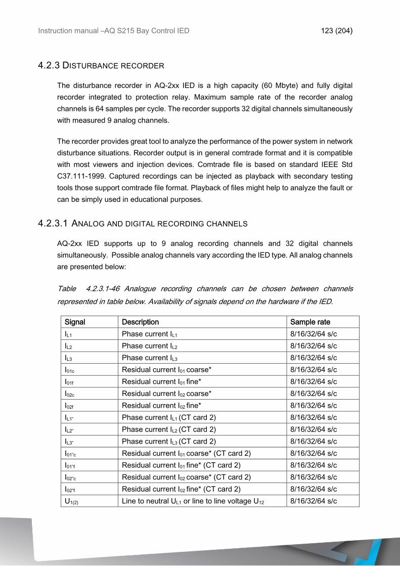
Instruction manual –AQ S215 Bay Control IED 123 (204)
4.2.3 DISTURBANCE RECORDER
The disturbance recorder in AQ-2xx IED is a high capacity (60 Mbyte) and fully digital
recorder integrated to protection relay. Maximum sample rate of the recorder analog
channels is 64 samples per cycle. The recorder supports 32 digital channels simultaneously
with measured 9 analog channels.
The recorder provides great tool to analyze the performance of the power system in network
disturbance situations. Recorder output is in general comtrade format and it is compatible
with most viewers and injection devices. Comtrade file is based on standard IEEE Std
C37.111-1999. Captured recordings can be injected as playback with secondary testing
tools those support comtrade file format. Playback of files might help to analyze the fault or
can be simply used in educational purposes.
4.2.3.1 ANALOG AND DIGITAL RECORDING CHANNELS
AQ-2xx IED supports up to 9 analog recording channels and 32 digital channels
simultaneously. Possible analog channels vary according the IED type. All analog channels
are presented below:
Table 4.2.3.1-46 Analogue recording channels can be chosen between channels
represented in table below. Availability of signals depend on the hardware if the IED.
Signal Description Sample rate
IL1 Phase current IL1 8/16/32/64 s/c
IL2 Phase current IL2 8/16/32/64 s/c
IL3 Phase current IL3 8/16/32/64 s/c
I01c Residual current I01 coarse* 8/16/32/64 s/c
I01f Residual current I01 fine* 8/16/32/64 s/c
I02c Residual current I02 coarse* 8/16/32/64 s/c
I02f Residual current I02 fine* 8/16/32/64 s/c
IL1” Phase current IL1 (CT card 2) 8/16/32/64 s/c
IL2” Phase current IL2 (CT card 2) 8/16/32/64 s/c
IL3” Phase current IL3 (CT card 2) 8/16/32/64 s/c
I01”c Residual current I01 coarse* (CT card 2) 8/16/32/64 s/c
I01”f Residual current I01 fine* (CT card 2) 8/16/32/64 s/c
I02”c Residual current I02 coarse* (CT card 2) 8/16/32/64 s/c
I02”f Residual current I02 fine* (CT card 2) 8/16/32/64 s/c
U1(2) Line to neutral UL1 or line to line voltage U12 8/16/32/64 s/c

Instruction manual –AQ S215 Bay Control IED 124 (204)
U2(3) Line to neutral UL2 or line to line voltage U23 8/16/32/64 s/c
U3(1) Line to neutral UL3,line to line voltage U31, zero
sequence voltage U0 or synchrocheck voltage
USS
8/16/32/64 s/c
U0(ss) Zero sequence voltage U0 or synchrocheck
voltage USS
8/16/32/64 s/c
F tracked 1 Tracked frequency of reference 1 8/16/32/64 s/c
F tracked 2 Tracked frequency of reference 2 8/16/32/64 s/c
F tracked 3 Tracked frequency of reference 3 8/16/32/64 s/c
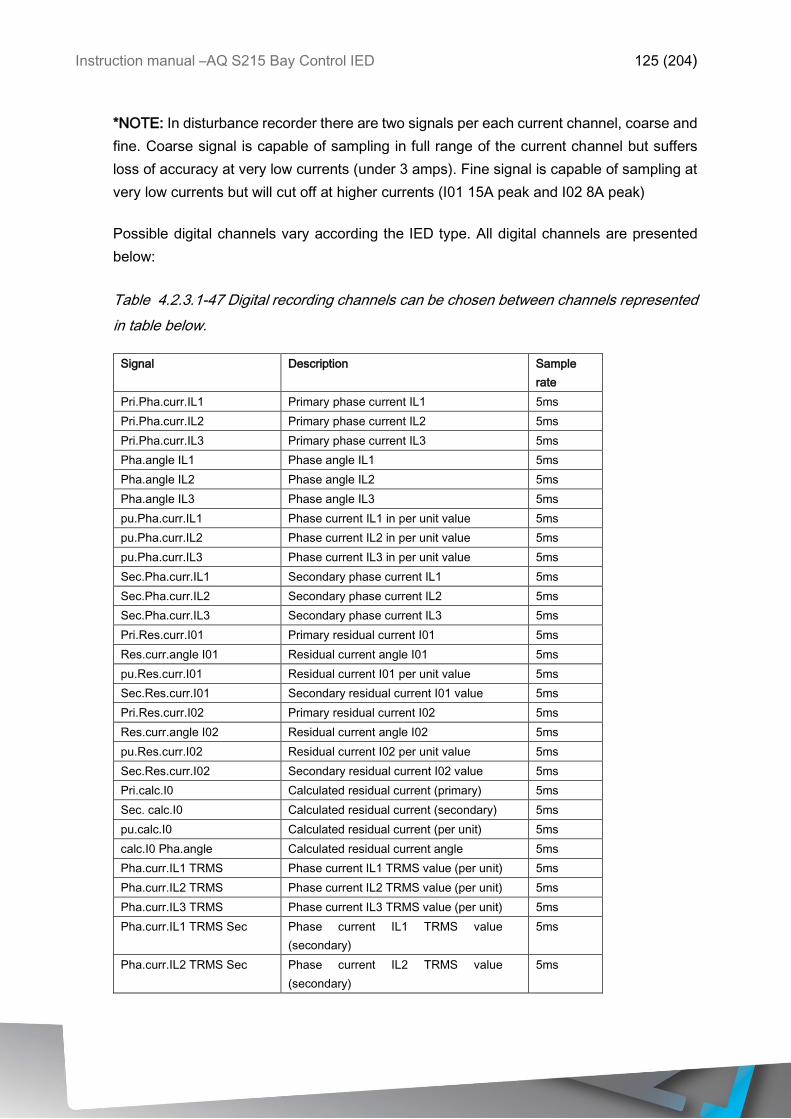
Instruction manual –AQ S215 Bay Control IED 125 (204)
*NOTE: In disturbance recorder there are two signals per each current channel, coarse and
fine. Coarse signal is capable of sampling in full range of the current channel but suffers
loss of accuracy at very low currents (under 3 amps). Fine signal is capable of sampling at
very low currents but will cut off at higher currents (I01 15A peak and I02 8A peak)
Possible digital channels vary according the IED type. All digital channels are presented
below:
Table 4.2.3.1-47 Digital recording channels can be chosen between channels represented
in table below.
Signal Description Sample
rate
Pri.Pha.curr.IL1 Primary phase current IL1 5ms
Pri.Pha.curr.IL2 Primary phase current IL2 5ms
Pri.Pha.curr.IL3 Primary phase current IL3 5ms
Pha.angle IL1 Phase angle IL1 5ms
Pha.angle IL2 Phase angle IL2 5ms
Pha.angle IL3 Phase angle IL3 5ms
pu.Pha.curr.IL1 Phase current IL1 in per unit value 5ms
pu.Pha.curr.IL2 Phase current IL2 in per unit value 5ms
pu.Pha.curr.IL3 Phase current IL3 in per unit value 5ms
Sec.Pha.curr.IL1 Secondary phase current IL1 5ms
Sec.Pha.curr.IL2 Secondary phase current IL2 5ms
Sec.Pha.curr.IL3 Secondary phase current IL3 5ms
Pri.Res.curr.I01 Primary residual current I01 5ms
Res.curr.angle I01 Residual current angle I01 5ms
pu.Res.curr.I01 Residual current I01 per unit value 5ms
Sec.Res.curr.I01 Secondary residual current I01 value 5ms
Pri.Res.curr.I02 Primary residual current I02 5ms
Res.curr.angle I02 Residual current angle I02 5ms
pu.Res.curr.I02 Residual current I02 per unit value 5ms
Sec.Res.curr.I02 Secondary residual current I02 value 5ms
Pri.calc.I0 Calculated residual current (primary) 5ms
Sec. calc.I0 Calculated residual current (secondary) 5ms
pu.calc.I0 Calculated residual current (per unit) 5ms
calc.I0 Pha.angle Calculated residual current angle 5ms
Pha.curr.IL1 TRMS Phase current IL1 TRMS value (per unit) 5ms
Pha.curr.IL2 TRMS Phase current IL2 TRMS value (per unit) 5ms
Pha.curr.IL3 TRMS Phase current IL3 TRMS value (per unit) 5ms
Pha.curr.IL1 TRMS Sec Phase current IL1 TRMS value
(secondary)
5ms
Pha.curr.IL2 TRMS Sec Phase current IL2 TRMS value
(secondary)
5ms
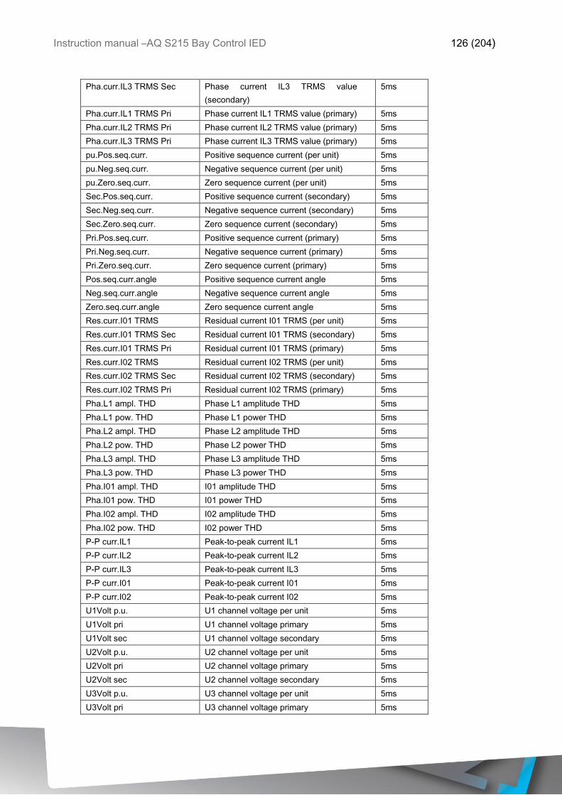
Instruction manual –AQ S215 Bay Control IED 126 (204)
Pha.curr.IL3 TRMS Sec Phase current IL3 TRMS value
(secondary)
5ms
Pha.curr.IL1 TRMS Pri Phase current IL1 TRMS value (primary) 5ms
Pha.curr.IL2 TRMS Pri Phase current IL2 TRMS value (primary) 5ms
Pha.curr.IL3 TRMS Pri Phase current IL3 TRMS value (primary) 5ms
pu.Pos.seq.curr. Positive sequence current (per unit) 5ms
pu.Neg.seq.curr. Negative sequence current (per unit) 5ms
pu.Zero.seq.curr. Zero sequence current (per unit) 5ms
Sec.Pos.seq.curr. Positive sequence current (secondary) 5ms
Sec.Neg.seq.curr. Negative sequence current (secondary) 5ms
Sec.Zero.seq.curr. Zero sequence current (secondary) 5ms
Pri.Pos.seq.curr. Positive sequence current (primary) 5ms
Pri.Neg.seq.curr. Negative sequence current (primary) 5ms
Pri.Zero.seq.curr. Zero sequence current (primary) 5ms
Pos.seq.curr.angle Positive sequence current angle 5ms
Neg.seq.curr.angle Negative sequence current angle 5ms
Zero.seq.curr.angle Zero sequence current angle 5ms
Res.curr.I01 TRMS Residual current I01 TRMS (per unit) 5ms
Res.curr.I01 TRMS Sec Residual current I01 TRMS (secondary) 5ms
Res.curr.I01 TRMS Pri Residual current I01 TRMS (primary) 5ms
Res.curr.I02 TRMS Residual current I02 TRMS (per unit) 5ms
Res.curr.I02 TRMS Sec Residual current I02 TRMS (secondary) 5ms
Res.curr.I02 TRMS Pri Residual current I02 TRMS (primary) 5ms
Pha.L1 ampl. THD Phase L1 amplitude THD 5ms
Pha.L1 pow. THD Phase L1 power THD 5ms
Pha.L2 ampl. THD Phase L2 amplitude THD 5ms
Pha.L2 pow. THD Phase L2 power THD 5ms
Pha.L3 ampl. THD Phase L3 amplitude THD 5ms
Pha.L3 pow. THD Phase L3 power THD 5ms
Pha.I01 ampl. THD I01 amplitude THD 5ms
Pha.I01 pow. THD I01 power THD 5ms
Pha.I02 ampl. THD I02 amplitude THD 5ms
Pha.I02 pow. THD I02 power THD 5ms
P-P curr.IL1 Peak-to-peak current IL1 5ms
P-P curr.IL2 Peak-to-peak current IL2 5ms
P-P curr.IL3 Peak-to-peak current IL3 5ms
P-P curr.I01 Peak-to-peak current I01 5ms
P-P curr.I02 Peak-to-peak current I02 5ms
U1Volt p.u. U1 channel voltage per unit 5ms
U1Volt pri U1 channel voltage primary 5ms
U1Volt sec U1 channel voltage secondary 5ms
U2Volt p.u. U2 channel voltage per unit 5ms
U2Volt pri U2 channel voltage primary 5ms
U2Volt sec U2 channel voltage secondary 5ms
U3Volt p.u. U3 channel voltage per unit 5ms
U3Volt pri U3 channel voltage primary 5ms
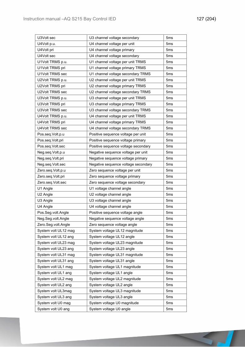
Instruction manual –AQ S215 Bay Control IED 127 (204)
U3Volt sec U3 channel voltage secondary 5ms
U4Volt p.u. U4 channel voltage per unit 5ms
U4Volt pri U4 channel voltage primary 5ms
U4Volt sec U4 channel voltage secondary 5ms
U1Volt TRMS p.u. U1 channel voltage per unit TRMS 5ms
U1Volt TRMS pri U1 channel voltage primary TRMS 5ms
U1Volt TRMS sec U1 channel voltage secondary TRMS 5ms
U2Volt TRMS p.u. U2 channel voltage per unit TRMS 5ms
U2Volt TRMS pri U2 channel voltage primary TRMS 5ms
U2Volt TRMS sec U2 channel voltage secondary TRMS 5ms
U3Volt TRMS p.u. U3 channel voltage per unit TRMS 5ms
U3Volt TRMS pri U3 channel voltage primary TRMS 5ms
U3Volt TRMS sec U3 channel voltage secondary TRMS 5ms
U4Volt TRMS p.u. U4 channel voltage per unit TRMS 5ms
U4Volt TRMS pri U4 channel voltage primary TRMS 5ms
U4Volt TRMS sec U4 channel voltage secondary TRMS 5ms
Pos.seq.Volt.p.u Positive sequence voltage per unit 5ms
Pos.seq.Volt.pri Positive sequence voltage primary 5ms
Pos.seq.Volt.sec Positive sequence voltage secondary 5ms
Neg.seq.Volt.p.u Negative sequence voltage per unit 5ms
Neg.seq.Volt.pri Negative sequence voltage primary 5ms
Neg.seq.Volt.sec Negative sequence voltage secondary 5ms
Zero.seq.Volt.p.u Zero sequence voltage per unit 5ms
Zero.seq.Volt.pri Zero sequence voltage primary 5ms
Zero.seq.Volt.sec Zero sequence voltage secondary 5ms
U1 Angle U1 voltage channel angle 5ms
U2 Angle U2 voltage channel angle 5ms
U3 Angle U3 voltage channel angle 5ms
U4 Angle U4 voltage channel angle 5ms
Pos.Seg.volt.Angle Positive sequence voltage angle 5ms
Neg.Seg.volt.Angle Negative sequence voltage angle 5ms
Zero.Seg.volt.Angle Zero sequence voltage angle 5ms
System volt UL12 mag System voltage UL12 magnitude 5ms
System volt UL12 ang System voltage UL12 angle 5ms
System volt UL23 mag System voltage UL23 magnitude 5ms
System volt UL23 ang System voltage UL23 angle 5ms
System volt UL31 mag System voltage UL31 magnitude 5ms
System volt UL31 ang System voltage UL31 angle 5ms
System volt UL1 mag System voltage UL1 magnitude 5ms
System volt UL1 ang System voltage UL1 angle 5ms
System volt UL2 mag System voltage UL2 magnitude 5ms
System volt UL2 ang System voltage UL2 angle 5ms
System volt UL3mag System voltage UL3 magnitude 5ms
System volt UL3 ang System voltage UL3 angle 5ms
System volt U0 mag System voltage U0 magnitude 5ms
System volt U0 ang System voltage U0 angle 5ms
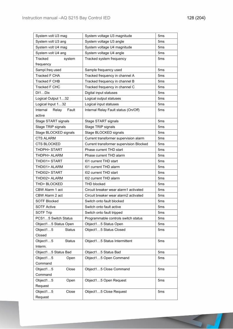
Instruction manual –AQ S215 Bay Control IED 128 (204)
System volt U3 mag System voltage U3 magnitude 5ms
System volt U3 ang System voltage U3 angle 5ms
System volt U4 mag System voltage U4 magnitude 5ms
System volt U4 ang System voltage U4 angle 5ms
Tracked system
frequency
Tracked system frequency 5ms
Sampl.freq used Sample frequency used 5ms
Tracked F CHA Tracked frequency in channel A 5ms
Tracked F CHB Tracked frequency in channel B 5ms
Tracked F CHC Tracked frequency in channel C 5ms
DI1…Dix Digital input statuses 5ms
Logical Output 1…32 Logical output statuses 5ms
Logical Input 1…32 Logical input statuses 5ms
Internal Relay Fault
active
Internal Relay Fault status (On/Off) 5ms
Stage START signals Stage START signals 5ms
Stage TRIP signals Stage TRIP signals 5ms
Stage BLOCKED signals Stage BLOCKED signals 5ms
CTS ALARM Current transformer supervision alarm 5ms
CTS BLOCKED Current transformer supervision Blocked 5ms
THDPH> START Phase current THD start 5ms
THDPH> ALARM Phase current THD alarm 5ms
THDI01> START I01 current THD start 5ms
THDI01> ALARM I01 current THD alarm 5ms
THDI02> START I02 current THD start 5ms
THDI02> ALARM I02 current THD alarm 5ms
THD> BLOCKED THD blocked 5ms
CBW Alarm 1 act Circuit breaker wear alarm1 activated 5ms
CBW Alarm 2 act Circuit breaker wear alarm2 activated 5ms
SOTF Blocked Switch onto fault blocked 5ms
SOTF Active Switch onto fault active 5ms
SOTF Trip Switch onto fault tripped 5ms
PCS1…5 Switch Status Programmable controls switch status 5ms
Object1…5 Status Open Object1…5 Status Open 5ms
Object1…5 Status
Closed
Object1…5 Status Closed 5ms
Object1…5 Status
Interm.
Object1…5 Status Intermittent 5ms
Object1…5 Status Bad Object1…5 Status Bad 5ms
Object1…5 Open
Command
Object1…5 Open Command 5ms
Object1…5 Close
Command
Object1…5 Close Command 5ms
Object1…5 Open
Request
Object1…5 Open Request 5ms
Object1…5 Close
Request
Object1…5 Close Request 5ms
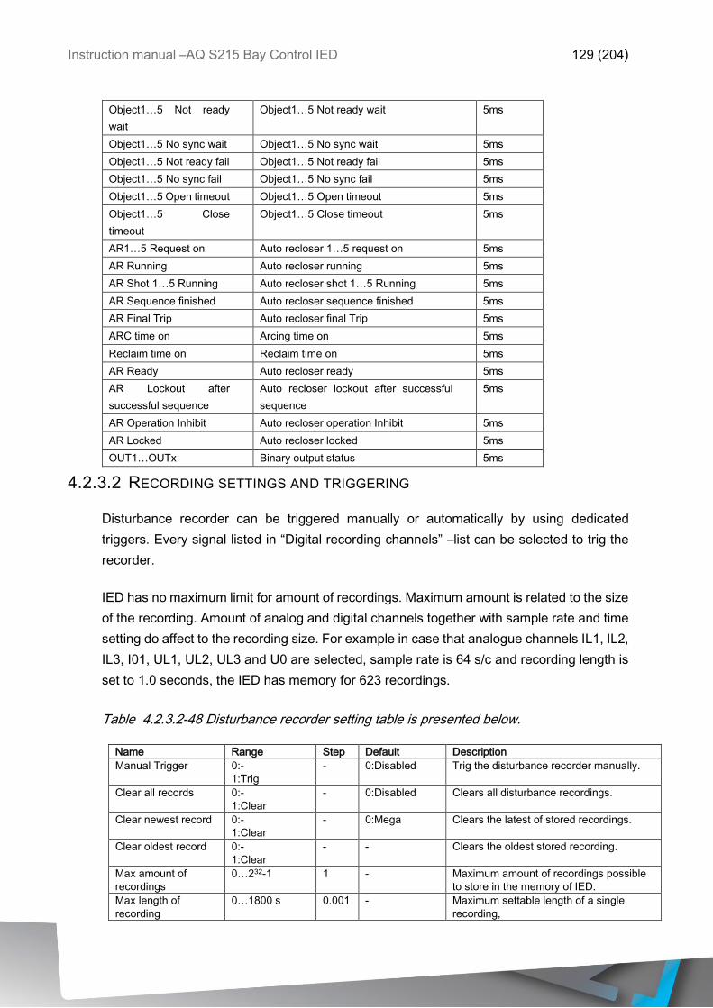
Instruction manual –AQ S215 Bay Control IED 129 (204)
Object1…5 Not ready
wait
Object1…5 Not ready wait 5ms
Object1…5 No sync wait Object1…5 No sync wait 5ms
Object1…5 Not ready fail Object1…5 Not ready fail 5ms
Object1…5 No sync fail Object1…5 No sync fail 5ms
Object1…5 Open timeout Object1…5 Open timeout 5ms
Object1…5 Close
timeout
Object1…5 Close timeout 5ms
AR1…5 Request on Auto recloser 1…5 request on 5ms
AR Running Auto recloser running 5ms
AR Shot 1…5 Running Auto recloser shot 1…5 Running 5ms
AR Sequence finished Auto recloser sequence finished 5ms
AR Final Trip Auto recloser final Trip 5ms
ARC time on Arcing time on 5ms
Reclaim time on Reclaim time on 5ms
AR Ready Auto recloser ready 5ms
AR Lockout after
successful sequence
Auto recloser lockout after successful
sequence
5ms
AR Operation Inhibit Auto recloser operation Inhibit 5ms
AR Locked Auto recloser locked 5ms
OUT1…OUTx Binary output status 5ms
4.2.3.2 RECORDING SETTINGS AND TRIGGERING
Disturbance recorder can be triggered manually or automatically by using dedicated
triggers. Every signal listed in “Digital recording channels” –list can be selected to trig the
recorder.
IED has no maximum limit for amount of recordings. Maximum amount is related to the size
of the recording. Amount of analog and digital channels together with sample rate and time
setting do affect to the recording size. For example in case that analogue channels IL1, IL2,
IL3, I01, UL1, UL2, UL3 and U0 are selected, sample rate is 64 s/c and recording length is
set to 1.0 seconds, the IED has memory for 623 recordings.
Table 4.2.3.2-48 Disturbance recorder setting table is presented below.
Name Range Step Default Description
Manual Trigger 0:-
1:Trig
- 0:Disabled Trig the disturbance recorder manually.
Clear all records 0:-
1:Clear
- 0:Disabled Clears all disturbance recordings.
Clear newest record 0:-
1:Clear
- 0:Mega
Clears the latest of stored recordings.
Clear oldest record 0:-
1:Clear
- - Clears the oldest stored recording.
Max amount of
recordings
0…232-1 1 - Maximum amount of recordings possible
to store in the memory of IED.
Max length of
recording
0…1800 s 0.001 - Maximum settable length of a single
recording,
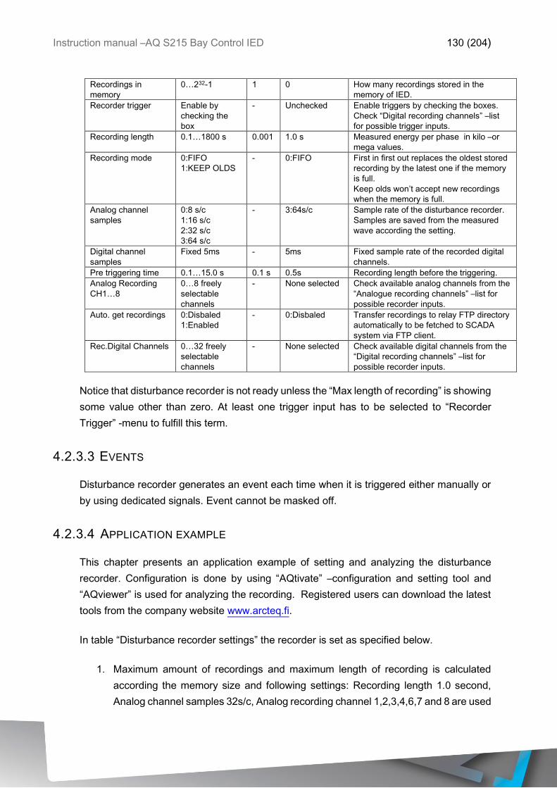
Instruction manual –AQ S215 Bay Control IED 130 (204)
Recordings in
memory
0…232-1 1 0
How many recordings stored in the
memory of IED.
Recorder trigger Enable by
checking the
box
- Unchecked
Enable triggers by checking the boxes.
Check “Digital recording channels” –list
for possible trigger inputs.
Recording length 0.1…1800 s 0.001 1.0 s
Measured energy per phase in kilo –or
mega values.
Recording mode 0:FIFO
1:KEEP OLDS
- 0:FIFO
First in first out replaces the oldest stored
recording by the latest one if the memory
is full.
Keep olds won’t accept new recordings
when the memory is full.
Analog channel
samples
0:8 s/c
1:16 s/c
2:32 s/c
3:64 s/c
- 3:64s/c Sample rate of the disturbance recorder.
Samples are saved from the measured
wave according the setting.
Digital channel
samples
Fixed 5ms - 5ms Fixed sample rate of the recorded digital
channels.
Pre triggering time 0.1…15.0 s 0.1 s 0.5s Recording length before the triggering.
Analog Recording
CH1…8
0…8 freely
selectable
channels
- None selected Check available analog channels from the
“Analogue recording channels” –list for
possible recorder inputs.
Auto. get recordings 0:Disbaled
1:Enabled
- 0:Disbaled Transfer recordings to relay FTP directory
automatically to be fetched to SCADA
system via FTP client.
Rec.Digital Channels 0…32 freely
selectable
channels
- None selected Check available digital channels from the
“Digital recording channels” –list for
possible recorder inputs.
Notice that disturbance recorder is not ready unless the “Max length of recording” is showing
some value other than zero. At least one trigger input has to be selected to “Recorder
Trigger” -menu to fulfill this term.
4.2.3.3 EVENTS
Disturbance recorder generates an event each time when it is triggered either manually or
by using dedicated signals. Event cannot be masked off.
4.2.3.4 APPLICATION EXAMPLE
This chapter presents an application example of setting and analyzing the disturbance
recorder. Configuration is done by using “AQtivate” –configuration and setting tool and
“AQviewer” is used for analyzing the recording. Registered users can download the latest
tools from the company website www.arcteq.fi.
In table “Disturbance recorder settings” the recorder is set as specified below.
1. Maximum amount of recordings and maximum length of recording is calculated
according the memory size and following settings: Recording length 1.0 second,
Analog channel samples 32s/c, Analog recording channel 1,2,3,4,6,7 and 8 are used

Instruction manual –AQ S215 Bay Control IED 131 (204)
and Recorder digital channels is taking samples of tracked system frequency every
5ms.
2. First overcurrent stage trip (I> TRIP) activation will trigger the recorder.
3. Length of the recording is 1.0 seconds. Pre triggering time 20 percent affects to the
recording in a way that 200ms is recorded before “I> TRIP” and 800ms is recorder
after.
4. Sample of each recorder analog signal is taken 64 times in a cycle. With 50Hz
system frequency it means that sample is taken every 313µs. Digital channels are
tracked every 5 milliseconds.
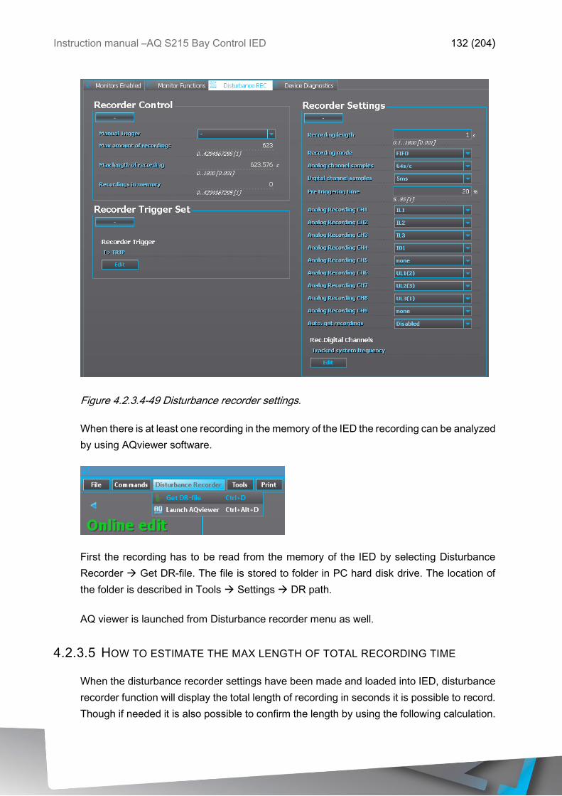
Instruction manual –AQ S215 Bay Control IED 132 (204)
Figure 4.2.3.4-49 Disturbance recorder settings.
When there is at least one recording in the memory of the IED the recording can be analyzed
by using AQviewer software.
First the recording has to be read from the memory of the IED by selecting Disturbance
Recorder Get DR-file. The file is stored to folder in PC hard disk drive. The location of
the folder is described in Tools Settings DR path.
AQ viewer is launched from Disturbance recorder menu as well.
4.2.3.5 HOW TO ESTIMATE THE MAX LENGTH OF TOTAL RECORDING TIME
When the disturbance recorder settings have been made and loaded into IED, disturbance
recorder function will display the total length of recording in seconds it is possible to record.
Though if needed it is also possible to confirm the length by using the following calculation.
Instruction manual –AQ S215 Bay Control IED 133 (204)
Please note that the following calculation assumes that DR doesn’t share the 64MB space
with any other files in the FTP.
16076647 samples
(fn*(AnCh + 1)*SR) + (200Hz*DiCh)
Where:
• fn is
• AnCh is the amount of recorded analog channels (which is then summed with 1
which stand for time stamp for each recorded sample)
• SR is the sample rate chosen by parameter (8,16,32 or 64 samples per cycle)
• 200Hz is the rate at which digital channels are always recorded (5ms)
• DiCh is the amount of digital channels recorded
• 16076647 is the amount of samples available in FTP if no other types of files are
saved.
As an example if nominal frequency is 50Hz and sample rate is 64s/c, all nine analog
channels are used and 2 digital channels are recorded the result is the following.
16076647 samples
(50Hz*(9 + 1)*64) + (200Hz*2)= 496s
Total sample reserve 16076647 is derived from the knowledge that one sample is always 4
bytes and the DR can use 64306588 bytes (total amount of bytes available divided by size
of one sample in bytes).
4.2.3.6 AQVIEWER
Disturbance recordings can be opened by choosing open folder icon or by going to File
Open. Recordings are packed comtrade files. Zip-file includes *.cfg and *.dat. AQviewer is
capable to open original packed zip files directly or comtrade files as they are as far as both
*.cfg and *.dat are located in same directory.
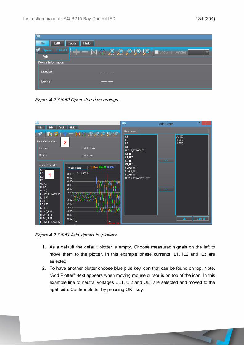
Instruction manual –AQ S215 Bay Control IED 134 (204)
Figure 4.2.3.6-50 Open stored recordings.
Figure 4.2.3.6-51 Add signals to plotters.
1. As a default the default plotter is empty. Choose measured signals on the left to
move them to the plotter. In this example phase currents IL1, IL2 and IL3 are
selected.
2. To have another plotter choose blue plus key icon that can be found on top. Note,
“Add Plotter” -text appears when moving mouse cursor is on top of the icon. In this
example line to neutral voltages UL1, Ul2 and UL3 are selected and moved to the
right side. Confirm plotter by pressing OK –key.
1
.
2
.
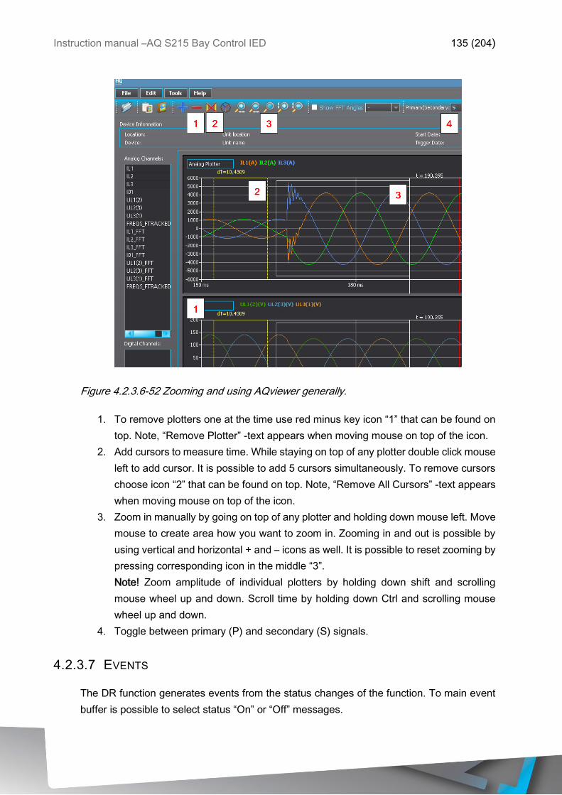
Instruction manual –AQ S215 Bay Control IED 135 (204)
Figure 4.2.3.6-52 Zooming and using AQviewer generally.
1. To remove plotters one at the time use red minus key icon “1” that can be found on
top. Note, “Remove Plotter” -text appears when moving mouse on top of the icon.
2. Add cursors to measure time. While staying on top of any plotter double click mouse
left to add cursor. It is possible to add 5 cursors simultaneously. To remove cursors
choose icon “2” that can be found on top. Note, “Remove All Cursors” -text appears
when moving mouse on top of the icon.
3. Zoom in manually by going on top of any plotter and holding down mouse left. Move
mouse to create area how you want to zoom in. Zooming in and out is possible by
using vertical and horizontal + and – icons as well. It is possible to reset zooming by
pressing corresponding icon in the middle “3”.
Note! Zoom amplitude of individual plotters by holding down shift and scrolling
mouse wheel up and down. Scroll time by holding down Ctrl and scrolling mouse
wheel up and down.
4. Toggle between primary (P) and secondary (S) signals.
4.2.3.7 EVENTS
The DR function generates events from the status changes of the function. To main event
buffer is possible to select status “On” or “Off” messages.
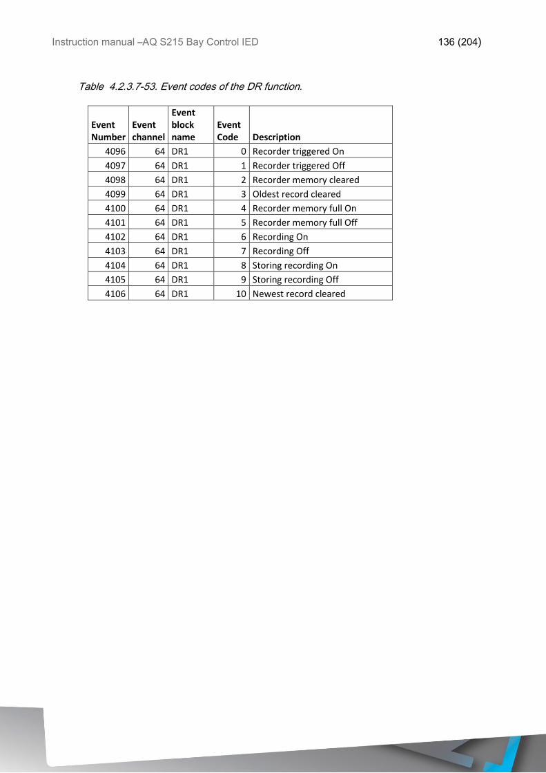
Instruction manual –AQ S215 Bay Control IED 136 (204)
Table 4.2.3.7-53. Event codes of the DR function.
Event Number
Event channel
Event block name
Event Code Description
4096 64 DR1 0 Recorder triggered On
4097 64 DR1 1 Recorder triggered Off
4098 64 DR1 2 Recorder memory cleared
4099 64 DR1 3 Oldest record cleared
4100 64 DR1 4 Recorder memory full On
4101 64 DR1 5 Recorder memory full Off
4102 64 DR1 6 Recording On
4103 64 DR1 7 Recording Off
4104 64 DR1 8 Storing recording On
4105 64 DR1 9 Storing recording Off
4106 64 DR1 10 Newest record cleared
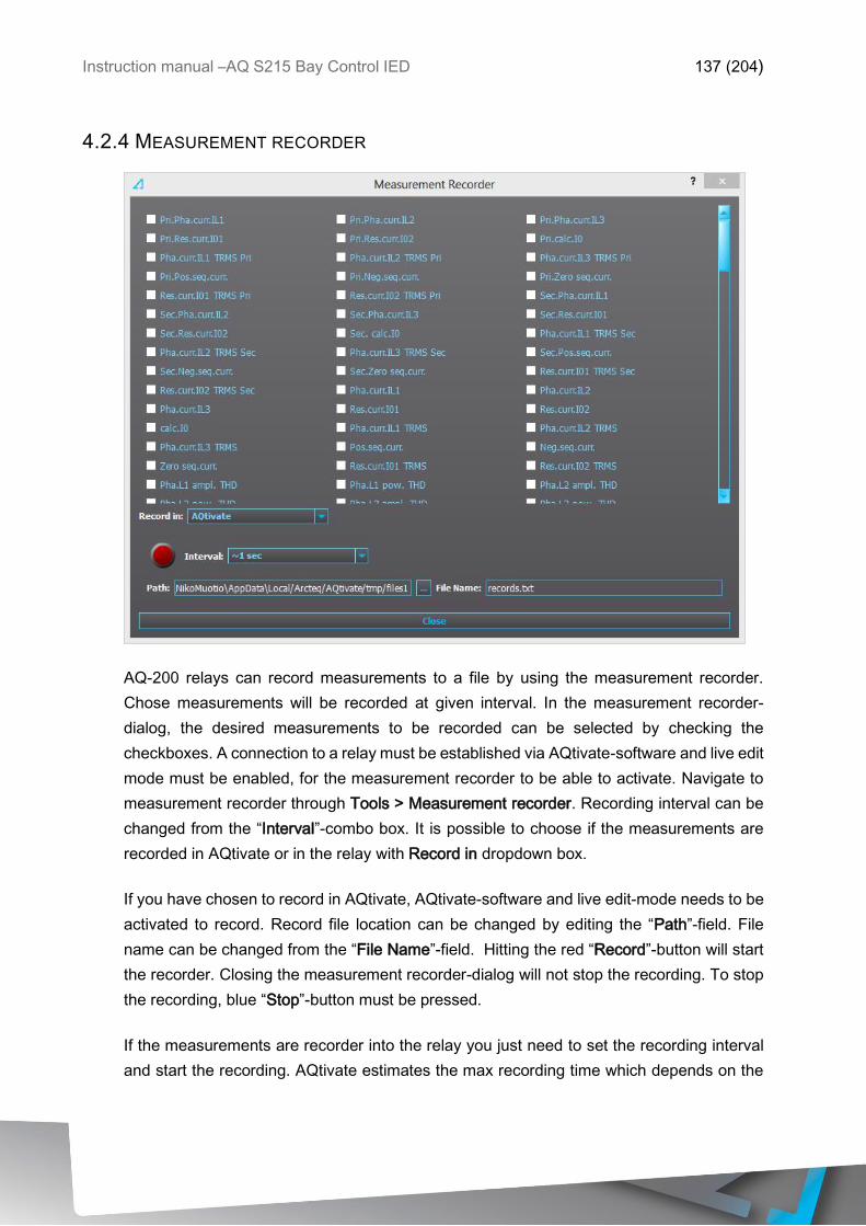
Instruction manual –AQ S215 Bay Control IED 137 (204)
4.2.4 MEASUREMENT RECORDER
AQ-200 relays can record measurements to a file by using the measurement recorder.
Chose measurements will be recorded at given interval. In the measurement recorder-
dialog, the desired measurements to be recorded can be selected by checking the
checkboxes. A connection to a relay must be established via AQtivate-software and live edit
mode must be enabled, for the measurement recorder to be able to activate. Navigate to
measurement recorder through Tools > Measurement recorder. Recording interval can be
changed from the “Interval”-combo box. It is possible to choose if the measurements are
recorded in AQtivate or in the relay with Record in dropdown box.
If you have chosen to record in AQtivate, AQtivate-software and live edit-mode needs to be
activated to record. Record file location can be changed by editing the “Path”-field. File
name can be changed from the “File Name”-field. Hitting the red “Record”-button will start
the recorder. Closing the measurement recorder-dialog will not stop the recording. To stop
the recording, blue “Stop”-button must be pressed.
If the measurements are recorder into the relay you just need to set the recording interval
and start the recording. AQtivate estimates the max recording time which depends on the
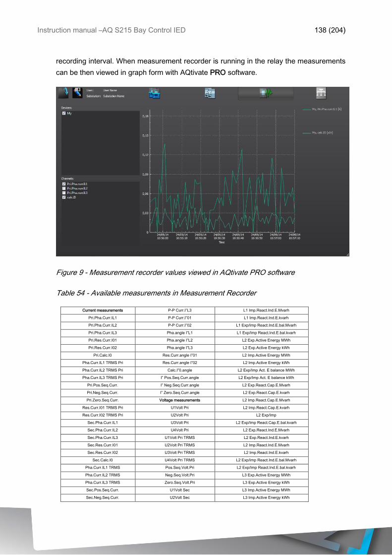
Instruction manual –AQ S215 Bay Control IED 138 (204)
recording interval. When measurement recorder is running in the relay the measurements
can be then viewed in graph form with AQtivate PRO software.
Figure 9 - Measurement recorder values viewed in AQtivate PRO software
Table 54 - Available measurements in Measurement Recorder
Current measurements P-P Curr.I”L3 L1 Imp.React.Ind.E.Mvarh
Pri.Pha.Curr.IL1 P-P Curr.I”01 L1 Imp.React.Ind.E.kvarh
Pri.Pha.Curr.IL2 P-P Curr.I”02 L1 Exp/Imp React.Ind.E.bal.Mvarh
Pri.Pha.Curr.IL3 Pha.angle I”L1 L1 Exp/Imp React.Ind.E.bal.kvarh
Pri.Res.Curr.I01 Pha.angle I”L2 L2 Exp.Active Energy MWh
Pri.Res.Curr.I02 Pha.angle I”L3 L2 Exp.Active Energy kWh
Pri.Calc.I0 Res.Curr.angle I”01 L2 Imp.Active Energy MWh
Pha.Curr.IL1 TRMS Pri Res.Curr.angle I”02 L2 Imp.Active Energy kWh
Pha.Curr.IL2 TRMS Pri Calc.I”0.angle L2 Exp/Imp Act. E balance MWh
Pha.Curr.IL3 TRMS Pri I” Pos.Seq.Curr.angle L2 Exp/Imp Act. E balance kWh
Pri.Pos.Seq.Curr. I” Neg.Seq.Curr.angle L2 Exp.React.Cap.E.Mvarh
Pri.Neg.Seq.Curr. I” Zero.Seq.Curr.angle L2 Exp.React.Cap.E.kvarh
Pri.Zero.Seq.Curr. Voltage measurements L2 Imp.React.Cap.E.Mvarh
Res.Curr.I01 TRMS Pri U1Volt Pri L2 Imp.React.Cap.E.kvarh
Res.Curr.I02 TRMS Pri U2Volt Pri L2 Exp/Imp
React.Cap.E.bal.Mvarh Sec.Pha.Curr.IL1 U3Volt Pri L2 Exp/Imp React.Cap.E.bal.kvarh
Sec.Pha.Curr.IL2 U4Volt Pri L2 Exp.React.Ind.E.Mvarh
Sec.Pha.Curr.IL3 U1Volt Pri TRMS L2 Exp.React.Ind.E.kvarh
Sec.Res.Curr.I01 U2Volt Pri TRMS L2 Imp.React.Ind.E.Mvarh
Sec.Res.Curr.I02 U3Volt Pri TRMS L2 Imp.React.Ind.E.kvarh
Sec.Calc.I0 U4Volt Pri TRMS L2 Exp/Imp React.Ind.E.bal.Mvarh
Pha.Curr.IL1 TRMS
Sec
Pos.Seq.Volt.Pri L2 Exp/Imp React.Ind.E.bal.kvarh
Pha.Curr.IL2 TRMS
Sec
Neg.Seq.Volt.Pri L3 Exp.Active Energy MWh
Pha.Curr.IL3 TRMS
Sec
Zero.Seq.Volt.Pri L3 Exp.Active Energy kWh
Sec.Pos.Seq.Curr. U1Volt Sec L3 Imp.Active Energy MWh
Sec.Neg.Seq.Curr. U2Volt Sec L3 Imp.Active Energy kWh
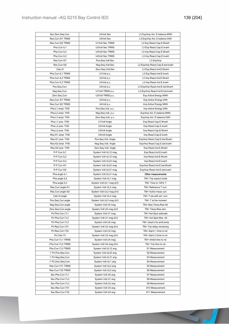
Instruction manual –AQ S215 Bay Control IED 139 (204)
Sec.Zero.Seq.Curr. U3Volt Sec L3 Exp/Imp Act. E balance MWh
Res.Curr.I01 TRMS
Sec
U4Volt Sec L3 Exp/Imp Act. E balance kWh
Res.Curr.I02 TRMS
Sec
U1Volt Sec TRMS L3 Exp.React.Cap.E.Mvarh
Pha.Curr.IL1 U2Volt Sec TRMS L3 Exp.React.Cap.E.kvarh
Pha.Curr.IL2 U3Volt Sec TRMS L3 Imp.React.Cap.E.Mvarh
Pha.Curr.IL3 U4Volt Sec TRMS L3 Imp.React.Cap.E.kvarh
Res.Curr.I01 Pos.Seq.Volt.Sec L3 Exp/Imp
React.Cap.E.bal.Mvarh Res.Curr.I02 Neg.Seq.Volt.Sec L3 Exp/Imp React.Cap.E.bal.kvarh
Calc.I0 Zero.Seq.Volt.Sec L3 Exp.React.Ind.E.Mvarh
Pha.Curr.IL1 TRMS U1Volt p.u. L3 Exp.React.Ind.E.kvarh
Pha.Curr.IL2 TRMS U2Volt p.u. L3 Imp.React.Ind.E.Mvarh
Pha.Curr.IL3 TRMS U3Volt p.u. L3 Imp.React.Ind.E.kvarh
Pos.Seq.Curr. U4Volt p.u. L3 Exp/Imp React.Ind.E.bal.Mvarh
Neg.Seq.Curr. U1Volt TRMS p.u. L3 Exp/Imp React.Ind.E.bal.kvarh
Zero.Seq.Curr. U2Volt TRMS p.u. Exp.Active Energy MWh
Res.Curr.I01 TRMS U3Volt p.u. Exp.Active Energy kWh
Res.Curr.I02 TRMS U4Volt p.u. Imp.Active Energy MWh
Pha.L1 ampl. THD Pos.Seq.Volt. p.u. Imp.Active Energy kWh
Pha.L2 ampl. THD Neg.Seq.Volt. p.u. Exp/Imp Act. E balance MWh
Pha.L3 ampl. THD Zero.Seq.Volt. p.u. Exp/Imp Act. E balance kWh
Pha.L1 pow. THD U1Volt Angle Exp.React.Cap.E.Mvarh
Pha.L2 pow. THD U2Volt Angle Exp.React.Cap.E.kvarh
Pha.L3 pow. THD U3Volt Angle Imp.React.Cap.E.Mvarh
Res.I01 ampl. THD U4Volt Angle Imp.React.Cap.E.kvarh
Res.I01 pow. THD Pos.Seq.Volt. Angle Exp/Imp React.Cap.E.bal.Mvarh
Res.I02 ampl. THD Neg.Seq.Volt. Angle Exp/Imp React.Cap.E.bal.kvarh
Res.I02 pow. THD Zero.Seq.Volt. Angle Exp.React.Ind.E.Mvarh
P-P Curr.IL1 System Volt UL12 mag Exp.React.Ind.E.kvarh
P-P Curr.IL2 System Volt UL12 mag
(kV)
Imp.React.Ind.E.Mvarh
P-P Curr.IL3 System Volt UL23 mag Imp.React.Ind.E.kvarh
P-P Curr.I01 System Volt UL23 mag
(kV)
Exp/Imp React.Ind.E.bal.Mvarh
P-P Curr.I02 System Volt UL31 mag Exp/Imp React.Ind.E.bal.kvarh
Pha.angle IL1 System Volt UL31 mag
(kV)
Other measurements
Pha.angle IL2 System Volt UL1 mag TM> Trip expect mode
Pha.angle IL3 System Volt UL1 mag (kV) TM> Time to 100% T
Res.Curr.angle I01 System Volt UL2 mag TM> Reference T curr.
Res.Curr.angle I02 System Volt UL2 mag (kV) TM> Active meas curr.
Calc.I0.angle System Volt UL3 mag TM> T est.with act. curr.
Pos.Seq.Curr.angle System Volt UL3 mag (kV) TM> T at the moment
Neg.Seq.Curr.angle System Volt U0 mag TM> Max.Temp.Rise All.
Zero.Seq.Curr.angle System Volt U0 mag (kV) TM> Temp.Rise atm.
Pri.Pha.Curr.I”L1 System Volt U1 mag TM> Hot Spot estimate
Pri.Pha.Curr.I”L2 System Volt U1 mag (kV) TM> Hot Spot Max. All
Pri.Pha.Curr.I”L3 System Volt U2 mag TM> Used k for amb.temp
Pri.Res.Curr.I”01 System Volt U2 mag (kV) TM> Trip delay remaining
Pri.Res.Curr.I”02 System Volt U3 mag TM> Alarm 1 time to rel.
Pri.Calc.I”0 System Volt U3 mag (kV) TM> Alarm 2 time to rel.
Pha.Curr.I”L1 TRMS
Pri
System Volt U4 mag TM> Inhibit time to rel.
Pha.Curr.I”L2 TRMS
Pri
System Volt U4 mag (kV) TM> Trip time to rel.
Pha.Curr.I”L3 TRMS
Pri
System Volt UL12 ang S1 Measurement
I” Pri.Pos.Seq.Curr. System Volt UL23 ang S2 Measurement
I” Pri.Neg.Seq.Curr. System Volt UL31 ang S3 Measurement
I” Pri.Zero.Seq.Curr. System Volt UL1 ang S4 Measurement
Res.Curr.I”01 TRMS
Pri
System Volt UL2 ang S5 Measurement
Res.Curr.I”02 TRMS
Pri
System Volt UL3 ang S6 Measurement
Sec.Pha.Curr.I”L1 System Volt U0 ang S7 Measurement
Sec.Pha.Curr.I”L2 System Volt U1 ang S8 Measurement
Sec.Pha.Curr.I”L3 System Volt U2 ang S9 Measurement
Sec.Res.Curr.I”01 System Volt U3 ang S10 Measurement
Sec.Res.Curr.I”02 System Volt U4 ang S11 Measurement
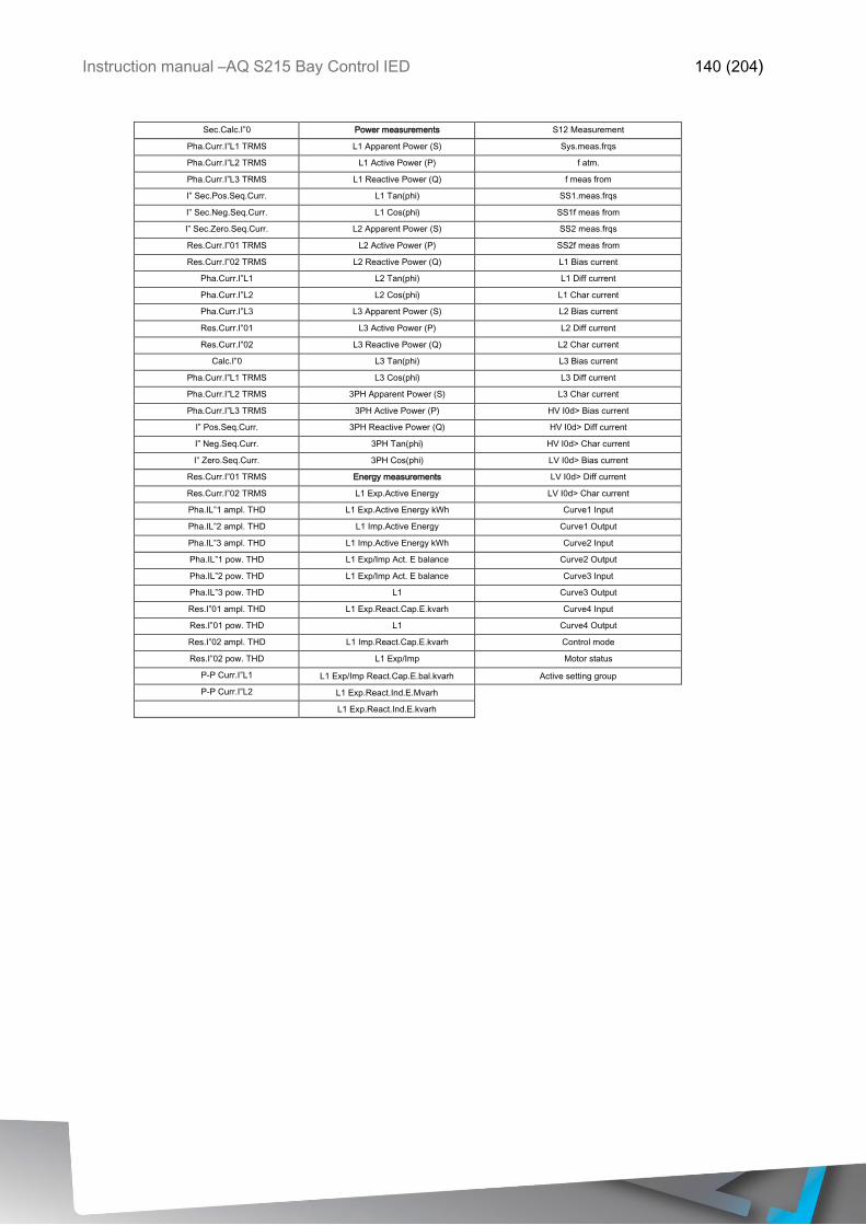
Instruction manual –AQ S215 Bay Control IED 140 (204)
Sec.Calc.I”0 Power measurements S12 Measurement
Pha.Curr.I”L1 TRMS
Sec
L1 Apparent Power (S) Sys.meas.frqs
Pha.Curr.I”L2 TRMS
Sec
L1 Active Power (P) f atm.
Pha.Curr.I”L3 TRMS
Sec
L1 Reactive Power (Q) f meas from
I” Sec.Pos.Seq.Curr. L1 Tan(phi) SS1.meas.frqs
I” Sec.Neg.Seq.Curr. L1 Cos(phi) SS1f meas from
I” Sec.Zero.Seq.Curr. L2 Apparent Power (S) SS2 meas.frqs
Res.Curr.I”01 TRMS
Sec
L2 Active Power (P) SS2f meas from
Res.Curr.I”02 TRMS
Sec
L2 Reactive Power (Q) L1 Bias current
Pha.Curr.I”L1 L2 Tan(phi) L1 Diff current
Pha.Curr.I”L2 L2 Cos(phi) L1 Char current
Pha.Curr.I”L3 L3 Apparent Power (S) L2 Bias current
Res.Curr.I”01 L3 Active Power (P) L2 Diff current
Res.Curr.I”02 L3 Reactive Power (Q) L2 Char current
Calc.I”0 L3 Tan(phi) L3 Bias current
Pha.Curr.I”L1 TRMS L3 Cos(phi) L3 Diff current
Pha.Curr.I”L2 TRMS 3PH Apparent Power (S) L3 Char current
Pha.Curr.I”L3 TRMS 3PH Active Power (P) HV I0d> Bias current
I” Pos.Seq.Curr. 3PH Reactive Power (Q) HV I0d> Diff current
I” Neg.Seq.Curr. 3PH Tan(phi) HV I0d> Char current
I” Zero.Seq.Curr. 3PH Cos(phi) LV I0d> Bias current
Res.Curr.I”01 TRMS Energy measurements LV I0d> Diff current
Res.Curr.I”02 TRMS L1 Exp.Active Energy
MWh
LV I0d> Char current
Pha.IL”1 ampl. THD L1 Exp.Active Energy kWh Curve1 Input
Pha.IL”2 ampl. THD L1 Imp.Active Energy
MWh
Curve1 Output
Pha.IL”3 ampl. THD L1 Imp.Active Energy kWh Curve2 Input
Pha.IL”1 pow. THD L1 Exp/Imp Act. E balance
MWh
Curve2 Output
Pha.IL”2 pow. THD L1 Exp/Imp Act. E balance
kWh
Curve3 Input
Pha.IL”3 pow. THD L1
Exp.React.Cap.E.Mvarh
Curve3 Output
Res.I”01 ampl. THD L1 Exp.React.Cap.E.kvarh Curve4 Input
Res.I”01 pow. THD L1
Imp.React.Cap.E.Mvarh
Curve4 Output
Res.I”02 ampl. THD L1 Imp.React.Cap.E.kvarh Control mode
Res.I”02 pow. THD L1 Exp/Imp
React.Cap.E.bal.Mvarh
Motor status
P-P Curr.I”L1 L1 Exp/Imp React.Cap.E.bal.kvarh Active setting group P-P Curr.I”L2 L1 Exp.React.Ind.E.Mvarh
L1 Exp.React.Ind.E.kvarh
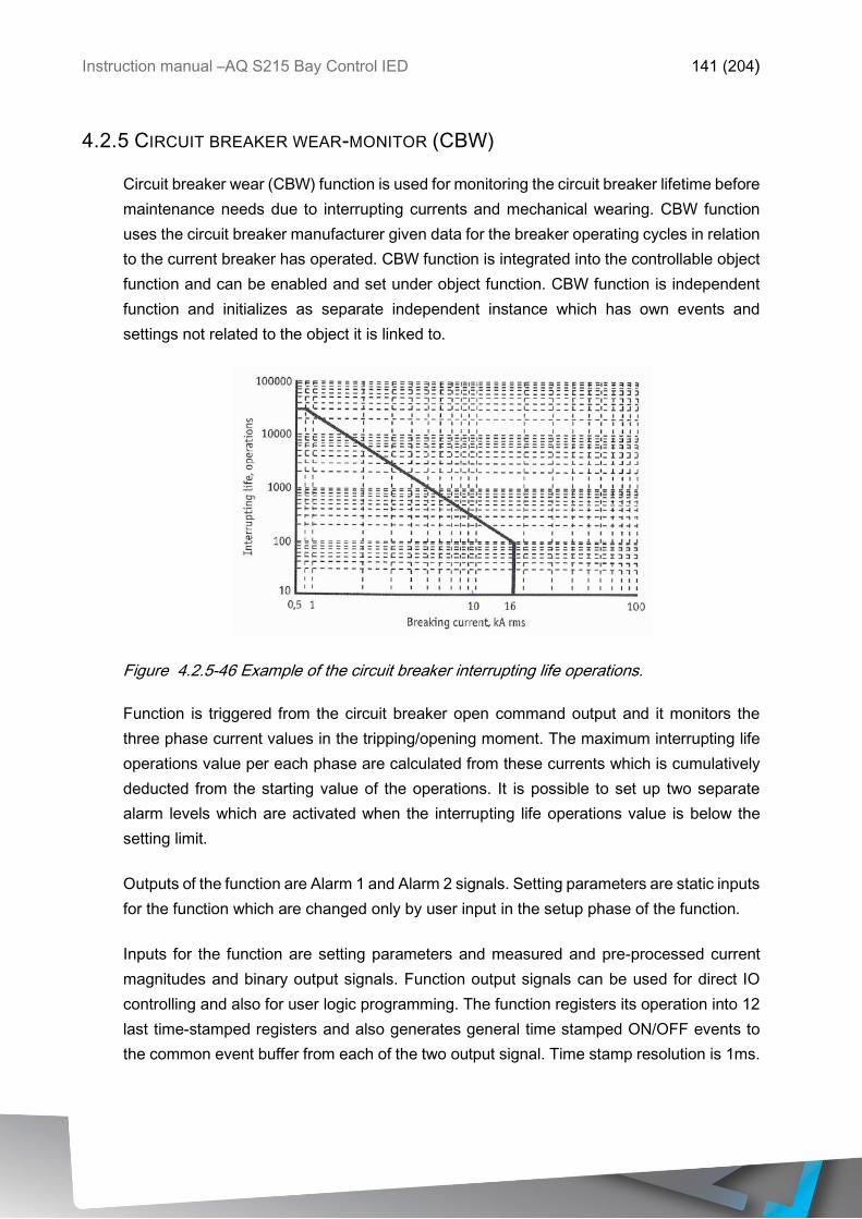
Instruction manual –AQ S215 Bay Control IED 141 (204)
4.2.5 CIRCUIT BREAKER WEAR-MONITOR (CBW)
Circuit breaker wear (CBW) function is used for monitoring the circuit breaker lifetime before
maintenance needs due to interrupting currents and mechanical wearing. CBW function
uses the circuit breaker manufacturer given data for the breaker operating cycles in relation
to the current breaker has operated. CBW function is integrated into the controllable object
function and can be enabled and set under object function. CBW function is independent
function and initializes as separate independent instance which has own events and
settings not related to the object it is linked to.
Figure 4.2.5-46 Example of the circuit breaker interrupting life operations.
Function is triggered from the circuit breaker open command output and it monitors the
three phase current values in the tripping/opening moment. The maximum interrupting life
operations value per each phase are calculated from these currents which is cumulatively
deducted from the starting value of the operations. It is possible to set up two separate
alarm levels which are activated when the interrupting life operations value is below the
setting limit.
Outputs of the function are Alarm 1 and Alarm 2 signals. Setting parameters are static inputs
for the function which are changed only by user input in the setup phase of the function.
Inputs for the function are setting parameters and measured and pre-processed current
magnitudes and binary output signals. Function output signals can be used for direct IO
controlling and also for user logic programming. The function registers its operation into 12
last time-stamped registers and also generates general time stamped ON/OFF events to
the common event buffer from each of the two output signal. Time stamp resolution is 1ms.
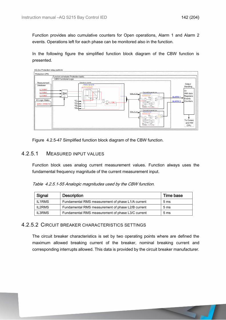
Instruction manual –AQ S215 Bay Control IED 142 (204)
Function provides also cumulative counters for Open operations, Alarm 1 and Alarm 2
events. Operations left for each phase can be monitored also in the function.
In the following figure the simplified function block diagram of the CBW function is
presented.
Figure 4.2.5-47 Simplified function block diagram of the CBW function.
4.2.5.1 MEASURED INPUT VALUES
Function block uses analog current measurement values. Function always uses the
fundamental frequency magnitude of the current measurement input.
Table 4.2.5.1-55 Analogic magnitudes used by the CBW function.
Signal Description Time base
IL1RMS Fundamental RMS measurement of phase L1/A current 5 ms
IL2RMS Fundamental RMS measurement of phase L2/B current 5 ms
IL3RMS Fundamental RMS measurement of phase L3/C current 5 ms
4.2.5.2 CIRCUIT BREAKER CHARACTERISTICS SETTINGS
The circuit breaker characteristics is set by two operating points where are defined the
maximum allowed breaking current of the breaker, nominal breaking current and
corresponding interrupts allowed. This data is provided by the circuit breaker manufacturer.
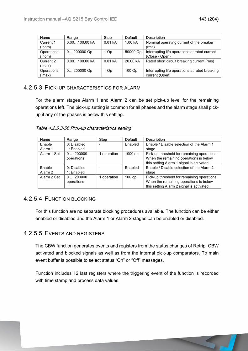
Instruction manual –AQ S215 Bay Control IED 143 (204)
Name Range Step Default Description
Current 1
(Inom)
0.00…100.00 kA 0.01 kA 1.00 kA Nominal operating current of the breaker
(rms)
Operations
(Inom)
0… 200000 Op 1 Op 50000 Op Interrupting life operations at rated current
(Close - Open)
Current 2
(Imax)
0.00…100.00 kA 0.01 kA 20.00 kA Rated short circuit breaking current (rms)
Operations
(Imax)
0… 200000 Op 1 Op 100 Op Interrupting life operations at rated breaking
current (Open)
4.2.5.3 PICK-UP CHARACTERISTICS FOR ALARM
For the alarm stages Alarm 1 and Alarm 2 can be set pick-up level for the remaining
operations left. The pick-up setting is common for all phases and the alarm stage shall pick-
up if any of the phases is below this setting.
Table 4.2.5.3-56 Pick-up characteristics setting
Name Range Step Default Description
Enable
Alarm 1
0: Disabled
1: Enabled
- Enabled Enable / Disable selection of the Alarm 1
stage
Alarm 1 Set 0 … 200000
operations
1 operation 1000 op Pick-up threshold for remaining operations.
When the remaining operations is below
this setting Alarm 1 signal is activated.
Enable
Alarm 2
0: Disabled
1: Enabled
- Enabled Enable / Disable selection of the Alarm 2
stage
Alarm 2 Set 0 … 200000
operations
1 operation 100 op Pick-up threshold for remaining operations.
When the remaining operations is below
this setting Alarm 2 signal is activated.
4.2.5.4 FUNCTION BLOCKING
For this function are no separate blocking procedures available. The function can be either
enabled or disabled and the Alarm 1 or Alarm 2 stages can be enabled or disabled.
4.2.5.5 EVENTS AND REGISTERS
The CBW function generates events and registers from the status changes of Retrip, CBW
activated and blocked signals as well as from the internal pick-up comparators. To main
event buffer is possible to select status “On” or “Off” messages.
Function includes 12 last registers where the triggering event of the function is recorded
with time stamp and process data values.
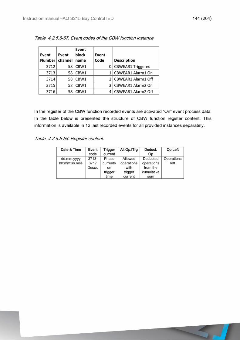
Instruction manual –AQ S215 Bay Control IED 144 (204)
Table 4.2.5.5-57. Event codes of the CBW function instance
Event Number
Event channel
Event block name
Event Code Description
3712 58 CBW1 0 CBWEAR1 Triggered
3713 58 CBW1 1 CBWEAR1 Alarm1 On
3714 58 CBW1 2 CBWEAR1 Alarm1 Off
3715 58 CBW1 3 CBWEAR1 Alarm2 On
3716 58 CBW1 4 CBWEAR1 Alarm2 Off
In the register of the CBW function recorded events are activated “On” event process data.
In the table below is presented the structure of CBW function register content. This
information is available in 12 last recorded events for all provided instances separately.
Table 4.2.5.5-58. Register content.
Date & Time Event
code
Trigger
current
All.Op.ITrg Deduct.
Op
Op.Left
dd.mm.yyyy
hh:mm:ss.mss
3713-
3717
Descr.
Phase
currents
on
trigger
time
Allowed
operations
with
trigger
current
Deducted
operations
from the
cumulative
sum
Operations
left
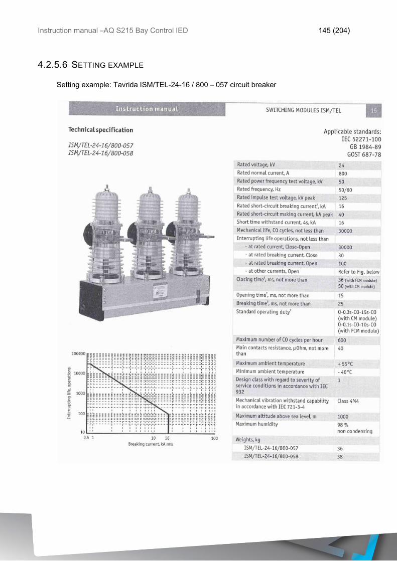
Instruction manual –AQ S215 Bay Control IED 145 (204)
4.2.5.6 SETTING EXAMPLE
Setting example: Tavrida ISM/TEL-24-16 / 800 – 057 circuit breaker

Instruction manual –AQ S215 Bay Control IED 146 (204)
Set the CBW stage as follows:
Parameter Value
Current 1 (Inom) 0.80 kA
Operation 1 (Inom) 30000 Op
Current 2 (Imax) 16.00 kA
Operations 2 (Imax) 100 Op
Enable Alarm 1 1: Enabled
Alarm 1 Set 1000
operations
Enable Alarm 2 1: Enabled
Alarm 2 Set 100 operations
With these settings Alarm 1 will be issued when any of the three phases cumulative
interruptions counter is below the set 1000 operations left and similarly when any of the
counters is below the set 100 operations left Alarm 2 will be issued.

Instruction manual –AQ S215 Bay Control IED 147 (204)
4.2.6 TOTAL HARMONIC DISTORTION MONITOR (THD)
Total harmonic distortion monitor function (THD) is used for monitoring the current harmonic
content. THD is a measurement of the harmonic distortion present and is defined as the
ratio of the sum of powers of all harmonic components to the power of fundamental
frequency.
Harmonics can be caused by different sources in the electric networks like electric machine
drives, thyristor controls etc. Monitoring of the THD of the currents can be used to alarm in
case if the harmonic content rises too high in cases if either the electric quality requirement
exist in the protected unit or in cases if process generated harmonics needs to be monitored.
THD function measures constantly phase and residual current magnitudes and the
harmonic content of the monitored signals up to 31.st harmonic component. When the THD
function is activated the THD measurements are available for displays also. User has
possibility to set also the alarming limits for each measured channels if required by the
application.
THD of the measured signals can be selected either amplitude- or power ratio THD. The
difference is in the calculation formula:
Power THD ratio is the sum of harmonic components squared divided by the fundamental
component squared.
THDP =Ix2
2 + Ix32 + Ix4
2 … Ix312
Ix12
, where
I = measured current,
x= measurement input,
n = harmonic number
Amplitude THD (percentage) is otherwise similar in difference of that the result is square
root of the Power THD:
THDA = √Ix2
2 + Ix32 + Ix4
2 … Ix312
Ix12
, where
I = measured current,
x= measurement input,
n = harmonic number
Both of these mentioned ways to calculate THD exist, while power THD is known by IEEE
and IEC defines the amplitude ratio.
Blocking signal and setting group selection controls the operating characteristics of the
function during normal operation if the alarming is selected to be active.
Outputs of the function are Start and Alarm act signals for phase current THD, I01 THD, I02
THD and Blocked signals. Setting parameters are static inputs for the function which are
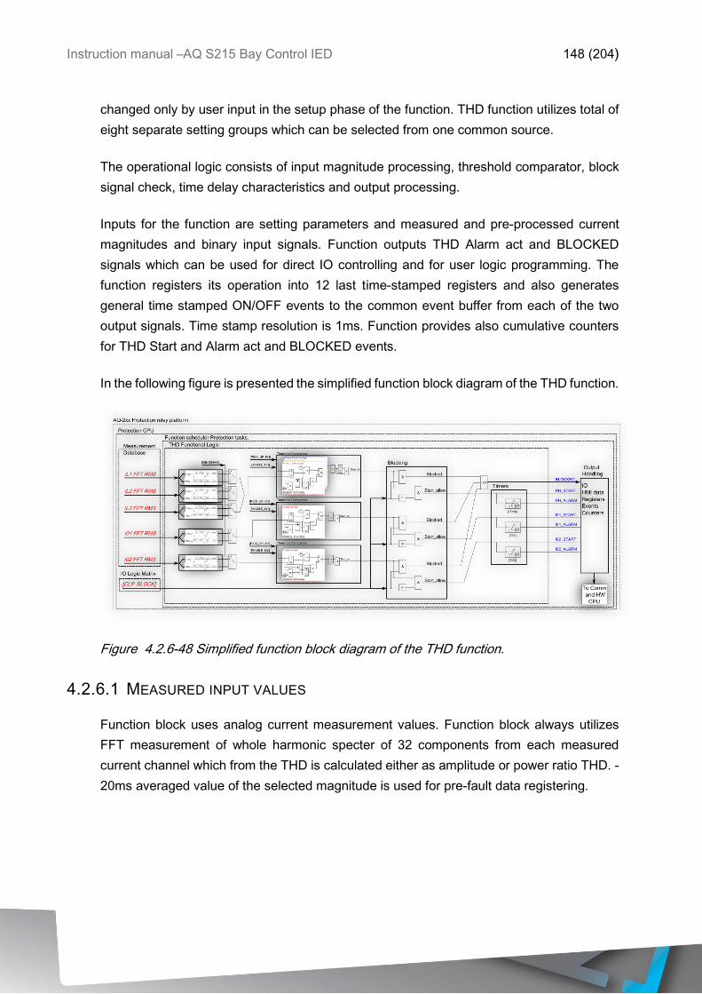
Instruction manual –AQ S215 Bay Control IED 148 (204)
changed only by user input in the setup phase of the function. THD function utilizes total of
eight separate setting groups which can be selected from one common source.
The operational logic consists of input magnitude processing, threshold comparator, block
signal check, time delay characteristics and output processing.
Inputs for the function are setting parameters and measured and pre-processed current
magnitudes and binary input signals. Function outputs THD Alarm act and BLOCKED
signals which can be used for direct IO controlling and for user logic programming. The
function registers its operation into 12 last time-stamped registers and also generates
general time stamped ON/OFF events to the common event buffer from each of the two
output signals. Time stamp resolution is 1ms. Function provides also cumulative counters
for THD Start and Alarm act and BLOCKED events.
In the following figure is presented the simplified function block diagram of the THD function.
Figure 4.2.6-48 Simplified function block diagram of the THD function.
4.2.6.1 MEASURED INPUT VALUES
Function block uses analog current measurement values. Function block always utilizes
FFT measurement of whole harmonic specter of 32 components from each measured
current channel which from the THD is calculated either as amplitude or power ratio THD. -
20ms averaged value of the selected magnitude is used for pre-fault data registering.

Instruction manual –AQ S215 Bay Control IED 149 (204)
Table 4.2.6.1-59 Analogic magnitudes used by the THD function.
Signal Description Time base
IL1FFT Fundamental RMS measurement of phase L1/A current 5 ms
IL2FFT Fundamental RMS measurement of phase L2/B current 5 ms
IL3FFT Fundamental RMS measurement of phase L3/C current 5 ms
I01FFT Fundamental RMS measurement of residual I01 current 5 ms
I02FFT Fundamental RMS measurement of residual I02 current 5 ms
Selection of the THD calculation method is made with a setting parameter commonly for all
of the measurement channels.
4.2.6.2 PICK-UP CHARACTERISTICS
Pick-up and activation of the THD function alarm is controlled by IsetPh, IsetI01 and IsetI02
pick-up setting parameters, which defines the maximum allowed measured current THD
before action from the function. In order to have alarm signals activated from the function,
the corresponding pick-up element needs to be activated by the Enable PH, Enable I01 and
Enable I02 setting parameters. Each pick-up element can be activated individually. The
function constantly calculates the ratio in between of the setting values and measured
magnitude (Im) per all three phases. Reset ratio of 97 % is inbuilt in the function and is
always related to the setting value. The setting value is common for all measured phases
and single-, dual- or all phases Im exceed of the Iset value will cause pick-up operation of
the function.
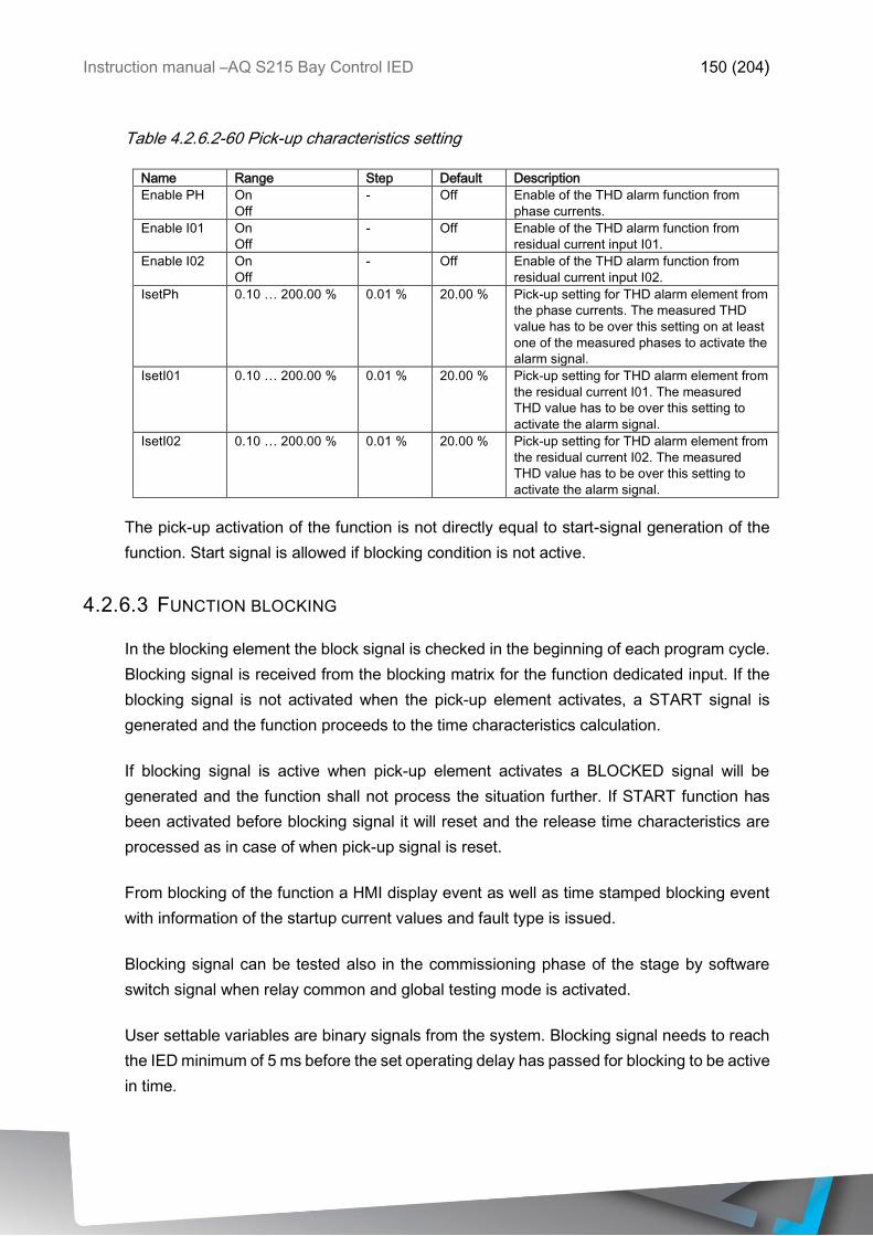
Instruction manual –AQ S215 Bay Control IED 150 (204)
Table 4.2.6.2-60 Pick-up characteristics setting
Name Range Step Default Description
Enable PH On
Off
- Off Enable of the THD alarm function from
phase currents.
Enable I01 On
Off
- Off Enable of the THD alarm function from
residual current input I01.
Enable I02 On
Off
- Off Enable of the THD alarm function from
residual current input I02.
IsetPh 0.10 … 200.00 % 0.01 % 20.00 % Pick-up setting for THD alarm element from
the phase currents. The measured THD
value has to be over this setting on at least
one of the measured phases to activate the
alarm signal.
IsetI01 0.10 … 200.00 % 0.01 % 20.00 % Pick-up setting for THD alarm element from
the residual current I01. The measured
THD value has to be over this setting to
activate the alarm signal.
IsetI02 0.10 … 200.00 % 0.01 % 20.00 % Pick-up setting for THD alarm element from
the residual current I02. The measured
THD value has to be over this setting to
activate the alarm signal.
The pick-up activation of the function is not directly equal to start-signal generation of the
function. Start signal is allowed if blocking condition is not active.
4.2.6.3 FUNCTION BLOCKING
In the blocking element the block signal is checked in the beginning of each program cycle.
Blocking signal is received from the blocking matrix for the function dedicated input. If the
blocking signal is not activated when the pick-up element activates, a START signal is
generated and the function proceeds to the time characteristics calculation.
If blocking signal is active when pick-up element activates a BLOCKED signal will be
generated and the function shall not process the situation further. If START function has
been activated before blocking signal it will reset and the release time characteristics are
processed as in case of when pick-up signal is reset.
From blocking of the function a HMI display event as well as time stamped blocking event
with information of the startup current values and fault type is issued.
Blocking signal can be tested also in the commissioning phase of the stage by software
switch signal when relay common and global testing mode is activated.
User settable variables are binary signals from the system. Blocking signal needs to reach
the IED minimum of 5 ms before the set operating delay has passed for blocking to be active
in time.
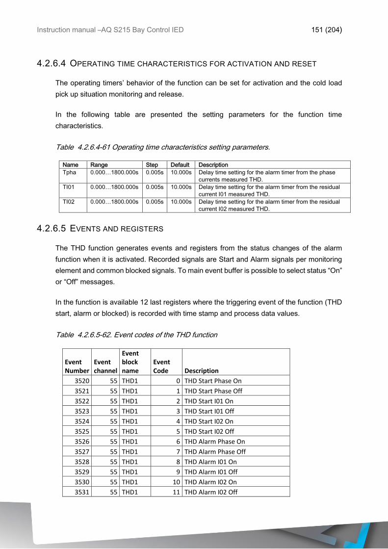
Instruction manual –AQ S215 Bay Control IED 151 (204)
4.2.6.4 OPERATING TIME CHARACTERISTICS FOR ACTIVATION AND RESET
The operating timers’ behavior of the function can be set for activation and the cold load
pick up situation monitoring and release.
In the following table are presented the setting parameters for the function time
characteristics.
Table 4.2.6.4-61 Operating time characteristics setting parameters.
Name Range Step Default Description
Tpha 0.000…1800.000s 0.005s 10.000s Delay time setting for the alarm timer from the phase
currents measured THD.
TI01 0.000…1800.000s 0.005s 10.000s Delay time setting for the alarm timer from the residual
current I01 measured THD.
TI02 0.000…1800.000s 0.005s 10.000s Delay time setting for the alarm timer from the residual
current I02 measured THD.
4.2.6.5 EVENTS AND REGISTERS
The THD function generates events and registers from the status changes of the alarm
function when it is activated. Recorded signals are Start and Alarm signals per monitoring
element and common blocked signals. To main event buffer is possible to select status “On”
or “Off” messages.
In the function is available 12 last registers where the triggering event of the function (THD
start, alarm or blocked) is recorded with time stamp and process data values.
Table 4.2.6.5-62. Event codes of the THD function
Event Number
Event channel
Event block name
Event Code Description
3520 55 THD1 0 THD Start Phase On
3521 55 THD1 1 THD Start Phase Off
3522 55 THD1 2 THD Start I01 On
3523 55 THD1 3 THD Start I01 Off
3524 55 THD1 4 THD Start I02 On
3525 55 THD1 5 THD Start I02 Off
3526 55 THD1 6 THD Alarm Phase On
3527 55 THD1 7 THD Alarm Phase Off
3528 55 THD1 8 THD Alarm I01 On
3529 55 THD1 9 THD Alarm I01 Off
3530 55 THD1 10 THD Alarm I02 On
3531 55 THD1 11 THD Alarm I02 Off
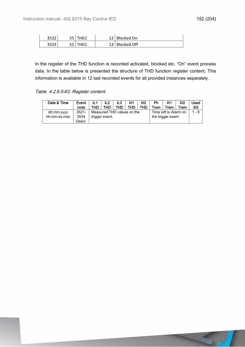
Instruction manual –AQ S215 Bay Control IED 152 (204)
3532 55 THD1 12 Blocked On
3533 55 THD1 13 Blocked Off
In the register of the THD function is recorded activated, blocked etc. “On” event process
data. In the table below is presented the structure of THD function register content. This
information is available in 12 last recorded events for all provided instances separately.
Table 4.2.6.5-63. Register content.
Date & Time Event
code
IL1
THD
IL2
THD
IL3
THD
I01
THD
I02
THD
Ph
Trem
I01
Trem
I02
Trem
Used
SG
dd.mm.yyyy
hh:mm:ss.mss
3521-
3534
Descr.
Measured THD values on the
trigger event.
Time left to Alarm on
the trigger event
1 - 8
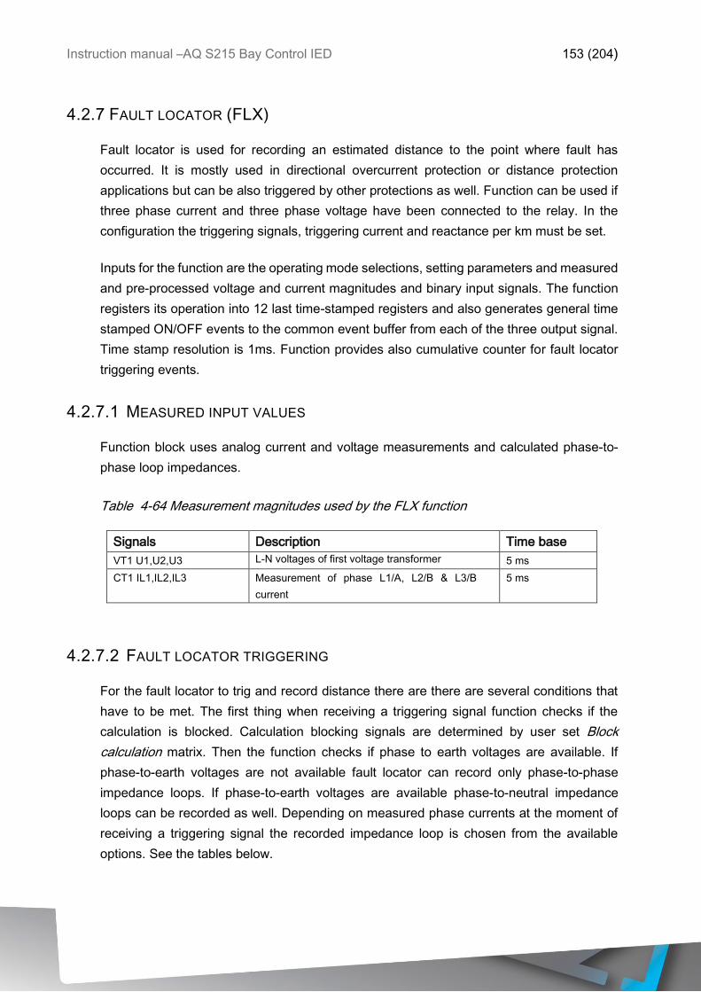
Instruction manual –AQ S215 Bay Control IED 153 (204)
4.2.7 FAULT LOCATOR (FLX)
Fault locator is used for recording an estimated distance to the point where fault has
occurred. It is mostly used in directional overcurrent protection or distance protection
applications but can be also triggered by other protections as well. Function can be used if
three phase current and three phase voltage have been connected to the relay. In the
configuration the triggering signals, triggering current and reactance per km must be set.
Inputs for the function are the operating mode selections, setting parameters and measured
and pre-processed voltage and current magnitudes and binary input signals. The function
registers its operation into 12 last time-stamped registers and also generates general time
stamped ON/OFF events to the common event buffer from each of the three output signal.
Time stamp resolution is 1ms. Function provides also cumulative counter for fault locator
triggering events.
4.2.7.1 MEASURED INPUT VALUES
Function block uses analog current and voltage measurements and calculated phase-to-
phase loop impedances.
Table 4-64 Measurement magnitudes used by the FLX function
Signals Description Time base
VT1 U1,U2,U3 L-N voltages of first voltage transformer 5 ms
CT1 IL1,IL2,IL3 Measurement of phase L1/A, L2/B & L3/B
current
5 ms
4.2.7.2 FAULT LOCATOR TRIGGERING
For the fault locator to trig and record distance there are there are several conditions that
have to be met. The first thing when receiving a triggering signal function checks if the
calculation is blocked. Calculation blocking signals are determined by user set Block
calculation matrix. Then the function checks if phase to earth voltages are available. If
phase-to-earth voltages are not available fault locator can record only phase-to-phase
impedance loops. If phase-to-earth voltages are available phase-to-neutral impedance
loops can be recorded as well. Depending on measured phase currents at the moment of
receiving a triggering signal the recorded impedance loop is chosen from the available
options. See the tables below.
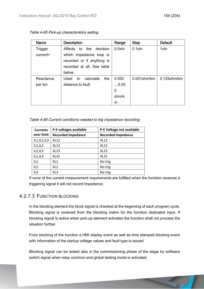
Instruction manual –AQ S215 Bay Control IED 154 (204)
Table 4-65 Pick-up characteristics setting
Name Description Range Step Default
Trigger
current>
Affects to the decision
which impedance loop is
recorded or if anything is
recorded at all. See table
below.
0.0xIn 0.1xIn 1xIn
Reactance
per km
Used to calculate the
distance to fault
0.000
…5.00
0
ohm/k
m
0.001ohm/km 0.125ohm/km
Table 4-66 Current conditions needed to trig impedance recording.
Currents over limit
P-E voltages available P-E Voltage not available
Recorded impedance Recorded impedance
IL1,IL2,IL3 XL12 XL12
IL1,IL2 XL12 XL12
IL2,IL3 XL23 XL23
IL1,IL3 XL31 XL31
IL1 XL1 No trig
IL2 XL2 No trig
IL3 XL3 No trig
If none of the current measurement requirements are fulfilled when the function receives a
triggering signal it will not record impedance.
4.2.7.3 FUNCTION BLOCKING
In the blocking element the block signal is checked at the beginning of each program cycle.
Blocking signal is received from the blocking matrix for the function dedicated input. If
blocking signal is active when pick-up element activates the function shall not process the
situation further.
From blocking of the function a HMI display event as well as time stamped blocking event
with information of the startup voltage values and fault type is issued.
Blocking signal can be tested also in the commissioning phase of the stage by software
switch signal when relay common and global testing mode is activated.
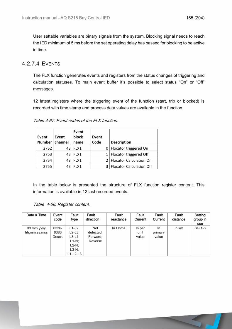
Instruction manual –AQ S215 Bay Control IED 155 (204)
User settable variables are binary signals from the system. Blocking signal needs to reach
the IED minimum of 5 ms before the set operating delay has passed for blocking to be active
in time.
4.2.7.4 EVENTS
The FLX function generates events and registers from the status changes of triggering and
calculation statuses. To main event buffer it’s possible to select status “On” or “Off”
messages.
12 latest registers where the triggering event of the function (start, trip or blocked) is
recorded with time stamp and process data values are available in the function.
Table 4-67. Event codes of the FLX function.
Event Number
Event channel
Event block name
Event Code Description
2752 43 FLX1 0 Flocator triggered On
2753 43 FLX1 1 Flocator triggered Off
2754 43 FLX1 2 Flocator Calculation On
2755 43 FLX1 3 Flocator Calculation Off
In the table below is presented the structure of FLX function register content. This
information is available in 12 last recorded events.
Table 4-68. Register content.
Date & Time Event
code
Fault
type
Fault
direction
Fault
reactance
Fault
Current
Fault
Current
Fault
distance
Setting
group in
use
dd.mm.yyyy
hh:mm:ss.mss
6336-
6383
Descr.
L1-L2;
L2-L3;
L3-L1;
L1-N;
L2-N;
L3-N;
L1-L2-L3
Not
detected;
Forward;
Reverse
In Ohms In per
unit
value
In
primary
value
In km SG 1-8

Instruction manual –AQ S215 Bay Control IED 156 (204)
4.2.8 MEASUREMENT VALUE RECORDER
Measurement value recorder function records the value of selected magnitudes at the time
of given trigger signal. An example application for this function is to record fault currents or
voltages at the time of tripping the breaker but it can be used also to record the values from
any user set trigger signal. Value recorder is capable of recording either per unit value or
primary value which is user settable. Optionally it is possible to set the function to record
the overcurrent or voltage fault type. The function operates instantly from trigger signal.
Additionally, the measurement value recorder function has integrated fault display which
displays the current fault values in case of I>, Idir>, I0>, I0dir>, f<, f>, U< or U> trips. When
any of these functions trip fault values and fault type are displayed over the mimic view. The
view can be enabled by activating VREC Trigger On in menu Tools Events and logs
Set alarm events. Resetting of the fault values is done by input selected in General menu.
Outputs of the function are selected measured values. Setting parameters are static inputs
for the function which are changed only by user input in the setup phase of the function.
4.2.8.1 MEASURED INPUT VALUES
Function block uses analog current and voltage measurement values. From these values
relay calculates the secondary and primary values of currents, voltages, powers,
impedances and other values.
Up to 8 magnitudes can be set to be recorded when function is triggered. Overcurrent fault
type, voltage fault type and tripped stage can be recorded and reported forward to SCADA.
NOTE: Available measurement values depend on the IED type. If only current analog
measurements are available, it is possible to use only signals which use just current. The
same applies if only voltage is available.
Table 4.2.8.1-69 Available measured values to be recorded in the measurement value
recorder function.
Currents
Signals Description
IL1ff, IL2ff,
IL3ff, I01ff,
I02ff
Fundamental frequency current measurement values of phase currents and residual
currents
IL1TRMS,
IL2TRMS,
IL3TRMS,
I01TRMS,
I02TRMS
TRMS current measurement values of phase currents and residual currents
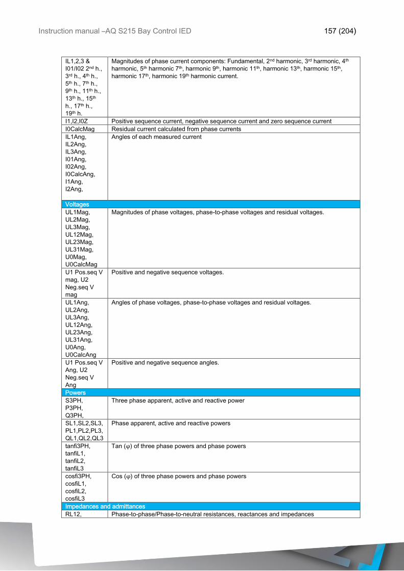
Instruction manual –AQ S215 Bay Control IED 157 (204)
IL1,2,3 &
I01/I02 2nd h.,
3rd h., 4th h.,
5th h., 7th h.,
9th h., 11th h.,
13th h., 15th
h., 17th h.,
19th h.
Magnitudes of phase current components: Fundamental, 2nd harmonic, 3rd harmonic, 4th
harmonic, 5th harmonic 7th, harmonic 9th, harmonic 11th, harmonic 13th, harmonic 15th,
harmonic 17th, harmonic 19th harmonic current.
I1,I2,I0Z Positive sequence current, negative sequence current and zero sequence current
I0CalcMag Residual current calculated from phase currents
IL1Ang,
IL2Ang,
IL3Ang,
I01Ang,
I02Ang,
I0CalcAng,
I1Ang,
I2Ang,
Angles of each measured current
Voltages
UL1Mag,
UL2Mag,
UL3Mag,
UL12Mag,
UL23Mag,
UL31Mag,
U0Mag,
U0CalcMag
Magnitudes of phase voltages, phase-to-phase voltages and residual voltages.
U1 Pos.seq V
mag, U2
Neg.seq V
mag
Positive and negative sequence voltages.
UL1Ang,
UL2Ang,
UL3Ang,
UL12Ang,
UL23Ang,
UL31Ang,
U0Ang,
U0CalcAng
Angles of phase voltages, phase-to-phase voltages and residual voltages.
U1 Pos.seq V
Ang, U2
Neg.seq V
Ang
Positive and negative sequence angles.
Powers
S3PH,
P3PH,
Q3PH,
Three phase apparent, active and reactive power
SL1,SL2,SL3,
PL1,PL2,PL3,
QL1,QL2,QL3
Phase apparent, active and reactive powers
tanfi3PH,
tanfiL1,
tanfiL2,
tanfiL3
Tan (φ) of three phase powers and phase powers
cosfi3PH,
cosfiL1,
cosfiL2,
cosfiL3
Cos (φ) of three phase powers and phase powers
Impedances and admittances
RL12, Phase-to-phase/Phase-to-neutral resistances, reactances and impedances
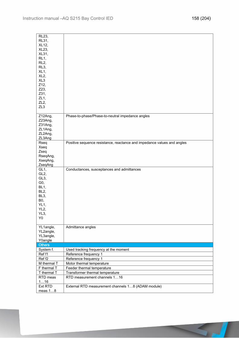
Instruction manual –AQ S215 Bay Control IED 158 (204)
RL23,
RL31,
XL12,
XL23,
XL31,
RL1,
RL2,
RL3,
XL1,
XL2,
XL3
Z12,
Z23,
Z31,
ZL1,
ZL2,
ZL3
Z12Ang,
Z23Ang,
Z31Ang,
ZL1Ang,
ZL2Ang,
ZL3Ang
Phase-to-phase/Phase-to-neutral impedance angles
Rseq
Xseq
Zseq
RseqAng,
XseqAng,
ZseqAng
Positive sequence resistance, reactance and impedance values and angles
GL1,
GL2,
GL3,
G0,
BL1,
BL2,
BL3,
B0,
YL1,
YL2,
YL3,
Y0
Conductances, susceptances and admittances
YL1angle,
YL2angle,
YL3angle,
Y0angle
Admittance angles
Others
System f. Used tracking frequency at the moment
Ref f1 Reference frequency 1
Ref f2 Reference frequency 1
M thermal T Motor thermal temperature
F thermal T Feeder thermal temperature
T thermal T Transformer thermal temperature
RTD meas
1…16
RTD measurement channels 1…16
Ext RTD
meas 1…8
External RTD measurement channels 1…8 (ADAM module)
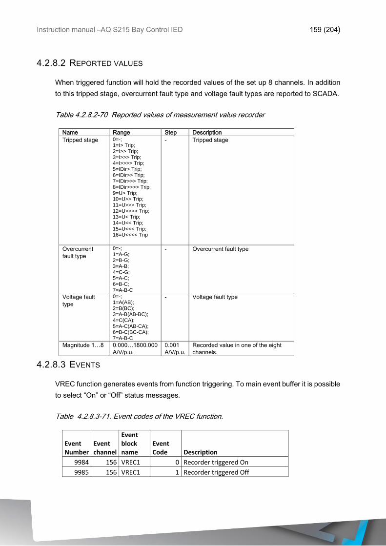
Instruction manual –AQ S215 Bay Control IED 159 (204)
4.2.8.2 REPORTED VALUES
When triggered function will hold the recorded values of the set up 8 channels. In addition
to this tripped stage, overcurrent fault type and voltage fault types are reported to SCADA.
Table 4.2.8.2-70 Reported values of measurement value recorder
Name Range Step Description
Tripped stage 0=-; 1=I> Trip; 2=I>> Trip; 3=I>>> Trip; 4=I>>>> Trip; 5=IDir> Trip; 6=IDir>> Trip; 7=IDir>>> Trip; 8=IDir>>>> Trip; 9=U> Trip; 10=U>> Trip; 11=U>>> Trip; 12=U>>>> Trip; 13=U< Trip; 14=U<< Trip; 15=U<<< Trip; 16=U<<<< Trip
- Tripped stage
Overcurrent
fault type
0=-; 1=A-G; 2=B-G; 3=A-B; 4=C-G; 5=A-C; 6=B-C; 7=A-B-C
- Overcurrent fault type
Voltage fault
type
0=-; 1=A(AB); 2=B(BC); 3=A-B(AB-BC); 4=C(CA); 5=A-C(AB-CA); 6=B-C(BC-CA); 7=A-B-C
- Voltage fault type
Magnitude 1…8 0.000…1800.000
A/V/p.u.
0.001
A/V/p.u.
Recorded value in one of the eight
channels.
4.2.8.3 EVENTS
VREC function generates events from function triggering. To main event buffer it is possible
to select “On” or “Off” status messages.
Table 4.2.8.3-71. Event codes of the VREC function.
Event Number
Event channel
Event block name
Event Code Description
9984 156 VREC1 0 Recorder triggered On
9985 156 VREC1 1 Recorder triggered Off
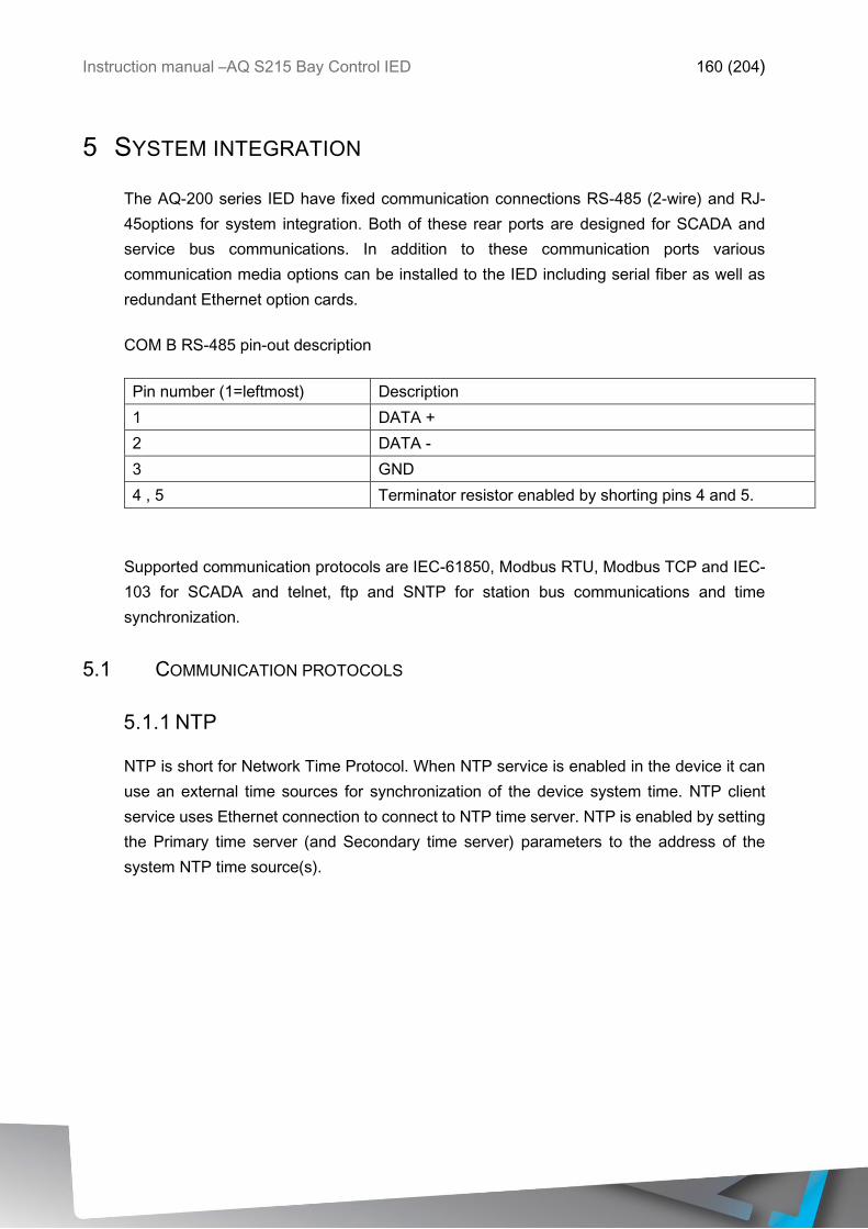
Instruction manual –AQ S215 Bay Control IED 160 (204)
5 SYSTEM INTEGRATION
The AQ-200 series IED have fixed communication connections RS-485 (2-wire) and RJ-
45options for system integration. Both of these rear ports are designed for SCADA and
service bus communications. In addition to these communication ports various
communication media options can be installed to the IED including serial fiber as well as
redundant Ethernet option cards.
COM B RS-485 pin-out description
Pin number (1=leftmost) Description
1 DATA +
2 DATA -
3 GND
4 , 5 Terminator resistor enabled by shorting pins 4 and 5.
Supported communication protocols are IEC-61850, Modbus RTU, Modbus TCP and IEC-
103 for SCADA and telnet, ftp and SNTP for station bus communications and time
synchronization.
5.1 COMMUNICATION PROTOCOLS
5.1.1 NTP
NTP is short for Network Time Protocol. When NTP service is enabled in the device it can
use an external time sources for synchronization of the device system time. NTP client
service uses Ethernet connection to connect to NTP time server. NTP is enabled by setting
the Primary time server (and Secondary time server) parameters to the address of the
system NTP time source(s).
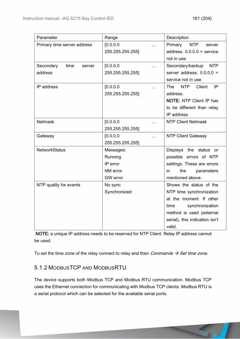
Instruction manual –AQ S215 Bay Control IED 161 (204)
Parameter Range Description
Primary time server address [0.0.0.0 …
255.255.255.255]
Primary NTP server
address. 0.0.0.0 = service
not in use.
Secondary time server
address
[0.0.0.0 …
255.255.255.255]
Secondary/backup NTP
server address. 0.0.0.0 =
service not in use.
IP address [0.0.0.0 …
255.255.255.255]
The NTP Client IP
address.
NOTE: NTP Client IP has
to be different than relay
IP address.
Netmask [0.0.0.0 …
255.255.255.255]
NTP Client Netmask
Gateway [0.0.0.0 …
255.255.255.255]
NTP Client Gateway
NetworkStatus Messages:
Running
IP error
NM error
GW error
Displays the status or
possible errors of NTP
settings. These are errors
in the parameters
mentioned above.
NTP quality for events No sync
Synchronized
Shows the status of the
NTP time synchronization
at the moment. If other
time synchronization
method is used (external
serial), this indication isn’t
valid.
NOTE: a unique IP address needs to be reserved for NTP Client. Relay IP address cannot
be used.
To set the time zone of the relay connect to relay and then Commands Set time zone.
5.1.2 MODBUSTCP AND MODBUSRTU
The device supports both Modbus TCP and Modbus RTU communication. Modbus TCP
uses the Ethernet connection for communicating with Modbus TCP clients. Modbus RTU is
a serial protocol which can be selected for the available serial ports.
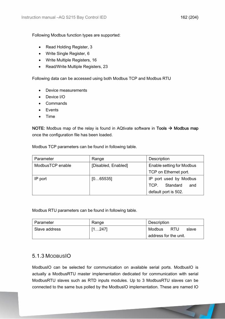
Instruction manual –AQ S215 Bay Control IED 162 (204)
Following Modbus function types are supported:
• Read Holding Register, 3
• Write Single Register, 6
• Write Multiple Registers, 16
• Read/Write Multiple Registers, 23
Following data can be accessed using both Modbus TCP and Modbus RTU
• Device measurements
• Device I/O
• Commands
• Events
• Time
NOTE: Modbus map of the relay is found in AQtivate software in Tools Modbus map
once the configuration file has been loaded.
Modbus TCP parameters can be found in following table.
Parameter Range Description
ModbusTCP enable [Disabled, Enabled] Enable setting for Modbus
TCP on Ethernet port.
IP port [0…65535] IP port used by Modbus
TCP. Standard and
default port is 502.
Modbus RTU parameters can be found in following table.
Parameter Range Description
Slave address [1…247] Modbus RTU slave
address for the unit.
5.1.3 MODBUSIO
ModbusIO can be selected for communication on available serial ports. ModbusIO is
actually a ModbusRTU master implementation dedicated for communication with serial
ModbusRTU slaves such as RTD inputs modules. Up to 3 ModbusRTU slaves can be
connected to the same bus polled by the ModbusIO implementation. These are named IO
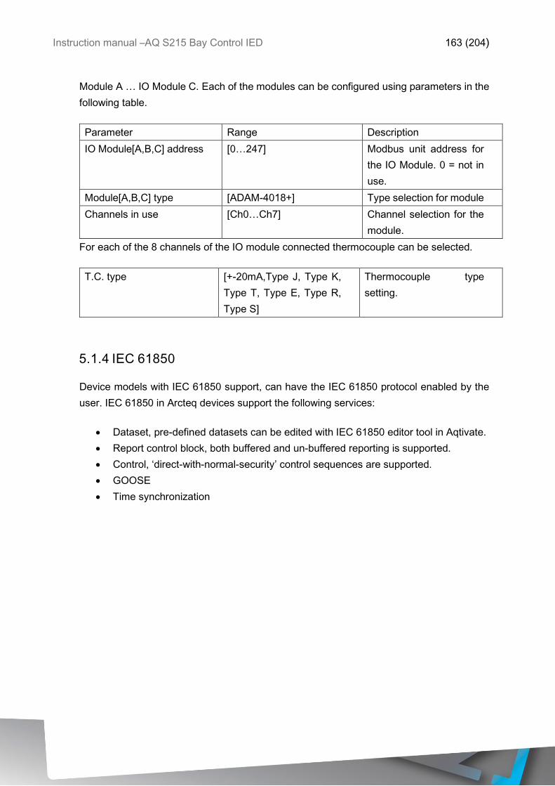
Instruction manual –AQ S215 Bay Control IED 163 (204)
Module A … IO Module C. Each of the modules can be configured using parameters in the
following table.
Parameter Range Description
IO Module[A,B,C] address [0…247] Modbus unit address for
the IO Module. 0 = not in
use.
Module[A,B,C] type [ADAM-4018+] Type selection for module
Channels in use [Ch0…Ch7] Channel selection for the
module.
For each of the 8 channels of the IO module connected thermocouple can be selected.
T.C. type [+-20mA,Type J, Type K,
Type T, Type E, Type R,
Type S]
Thermocouple type
setting.
5.1.4 IEC 61850
Device models with IEC 61850 support, can have the IEC 61850 protocol enabled by the
user. IEC 61850 in Arcteq devices support the following services:
• Dataset, pre-defined datasets can be edited with IEC 61850 editor tool in Aqtivate.
• Report control block, both buffered and un-buffered reporting is supported.
• Control, ‘direct-with-normal-security’ control sequences are supported.
• GOOSE
• Time synchronization
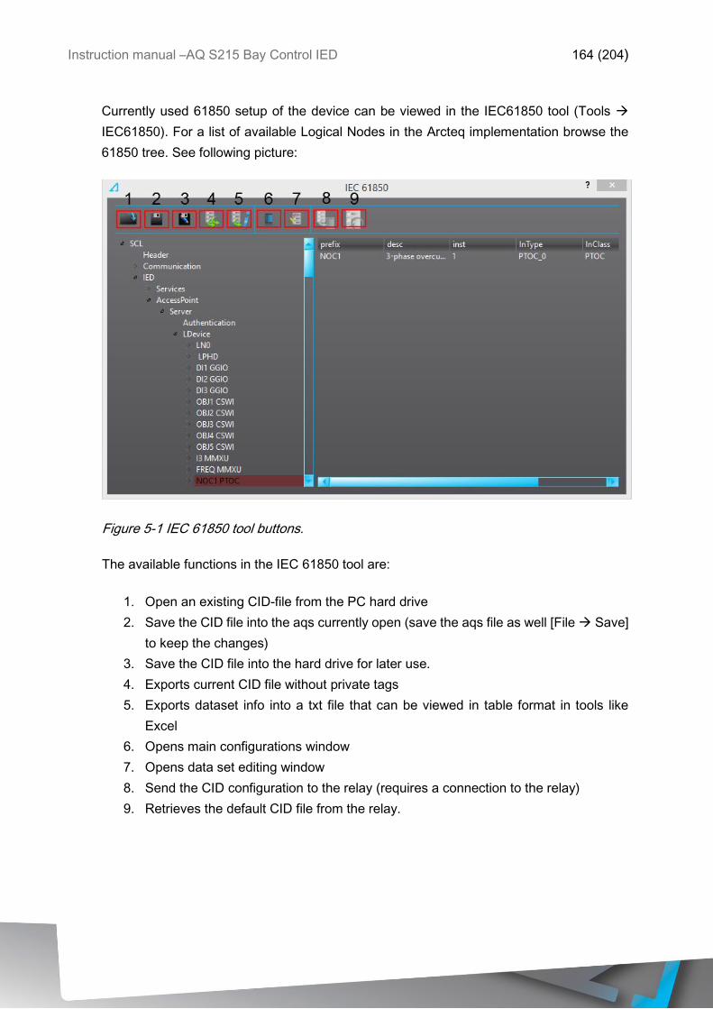
Instruction manual –AQ S215 Bay Control IED 164 (204)
Currently used 61850 setup of the device can be viewed in the IEC61850 tool (Tools
IEC61850). For a list of available Logical Nodes in the Arcteq implementation browse the
61850 tree. See following picture:
Figure 5-1 IEC 61850 tool buttons.
The available functions in the IEC 61850 tool are:
1. Open an existing CID-file from the PC hard drive
2. Save the CID file into the aqs currently open (save the aqs file as well [File Save]
to keep the changes)
3. Save the CID file into the hard drive for later use.
4. Exports current CID file without private tags
5. Exports dataset info into a txt file that can be viewed in table format in tools like
Excel
6. Opens main configurations window
7. Opens data set editing window
8. Send the CID configuration to the relay (requires a connection to the relay)
9. Retrieves the default CID file from the relay.
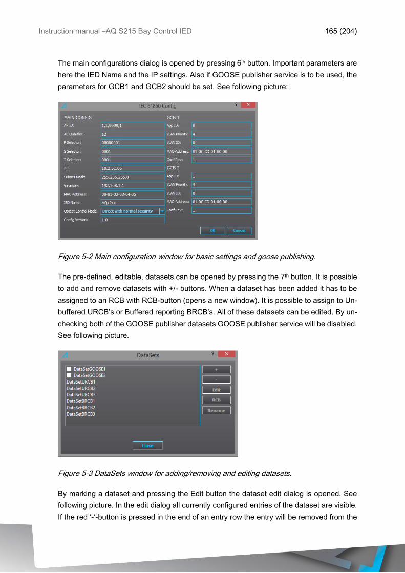
Instruction manual –AQ S215 Bay Control IED 165 (204)
The main configurations dialog is opened by pressing 6th button. Important parameters are
here the IED Name and the IP settings. Also if GOOSE publisher service is to be used, the
parameters for GCB1 and GCB2 should be set. See following picture:
Figure 5-2 Main configuration window for basic settings and goose publishing.
The pre-defined, editable, datasets can be opened by pressing the 7th button. It is possible
to add and remove datasets with +/- buttons. When a dataset has been added it has to be
assigned to an RCB with RCB-button (opens a new window). It is possible to assign to Un-
buffered URCB’s or Buffered reporting BRCB’s. All of these datasets can be edited. By un-
checking both of the GOOSE publisher datasets GOOSE publisher service will be disabled.
See following picture.
Figure 5-3 DataSets window for adding/removing and editing datasets.
By marking a dataset and pressing the Edit button the dataset edit dialog is opened. See
following picture. In the edit dialog all currently configured entries of the dataset are visible.
If the red ‘-‘-button is pressed in the end of an entry row the entry will be removed from the
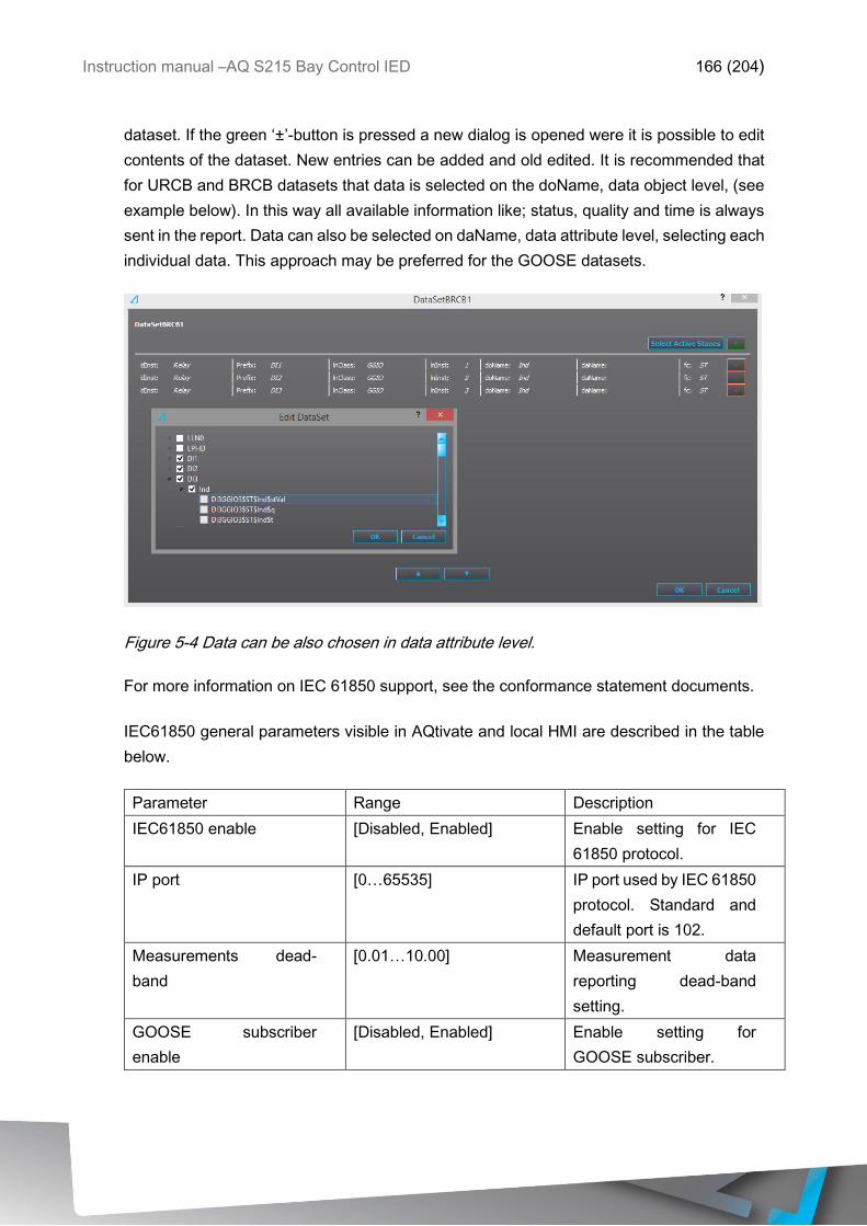
Instruction manual –AQ S215 Bay Control IED 166 (204)
dataset. If the green ‘±’-button is pressed a new dialog is opened were it is possible to edit
contents of the dataset. New entries can be added and old edited. It is recommended that
for URCB and BRCB datasets that data is selected on the doName, data object level, (see
example below). In this way all available information like; status, quality and time is always
sent in the report. Data can also be selected on daName, data attribute level, selecting each
individual data. This approach may be preferred for the GOOSE datasets.
Figure 5-4 Data can be also chosen in data attribute level.
For more information on IEC 61850 support, see the conformance statement documents.
IEC61850 general parameters visible in AQtivate and local HMI are described in the table
below.
Parameter Range Description
IEC61850 enable [Disabled, Enabled] Enable setting for IEC
61850 protocol.
IP port [0…65535] IP port used by IEC 61850
protocol. Standard and
default port is 102.
Measurements dead-
band
[0.01…10.00] Measurement data
reporting dead-band
setting.
GOOSE subscriber
enable
[Disabled, Enabled] Enable setting for
GOOSE subscriber.
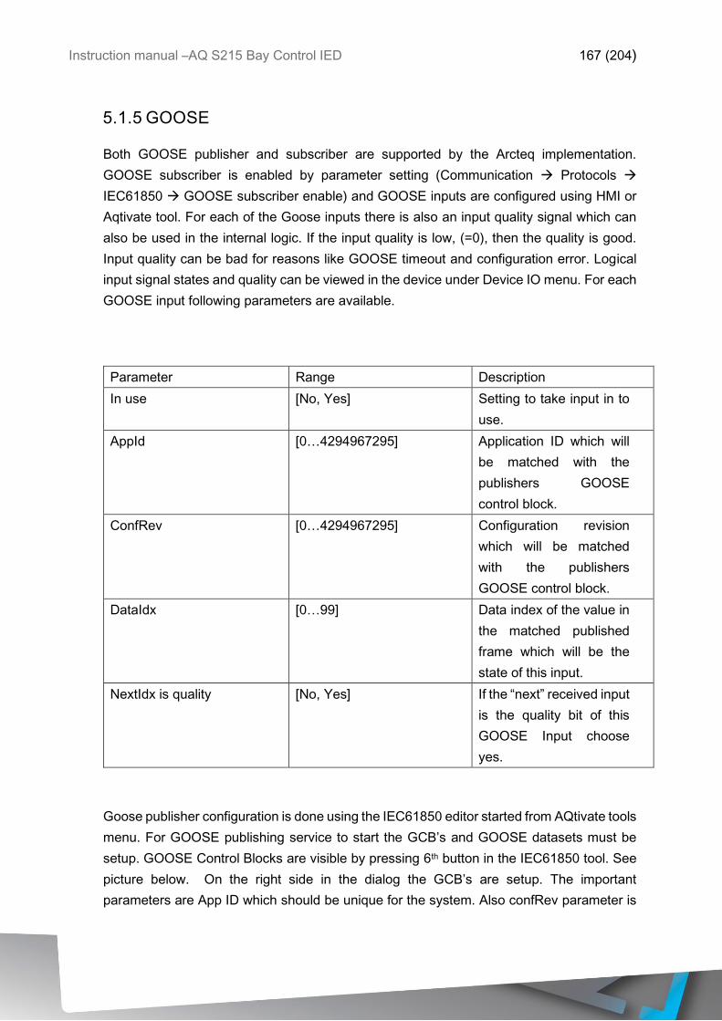
Instruction manual –AQ S215 Bay Control IED 167 (204)
5.1.5 GOOSE
Both GOOSE publisher and subscriber are supported by the Arcteq implementation.
GOOSE subscriber is enabled by parameter setting (Communication Protocols
IEC61850 GOOSE subscriber enable) and GOOSE inputs are configured using HMI or
Aqtivate tool. For each of the Goose inputs there is also an input quality signal which can
also be used in the internal logic. If the input quality is low, (=0), then the quality is good.
Input quality can be bad for reasons like GOOSE timeout and configuration error. Logical
input signal states and quality can be viewed in the device under Device IO menu. For each
GOOSE input following parameters are available.
Parameter Range Description
In use [No, Yes] Setting to take input in to
use.
AppId [0…4294967295] Application ID which will
be matched with the
publishers GOOSE
control block.
ConfRev [0…4294967295] Configuration revision
which will be matched
with the publishers
GOOSE control block.
DataIdx [0…99] Data index of the value in
the matched published
frame which will be the
state of this input.
NextIdx is quality [No, Yes] If the “next” received input
is the quality bit of this
GOOSE Input choose
yes.
Goose publisher configuration is done using the IEC61850 editor started from AQtivate tools
menu. For GOOSE publishing service to start the GCB’s and GOOSE datasets must be
setup. GOOSE Control Blocks are visible by pressing 6th button in the IEC61850 tool. See
picture below. On the right side in the dialog the GCB’s are setup. The important
parameters are App ID which should be unique for the system. Also confRev parameter is
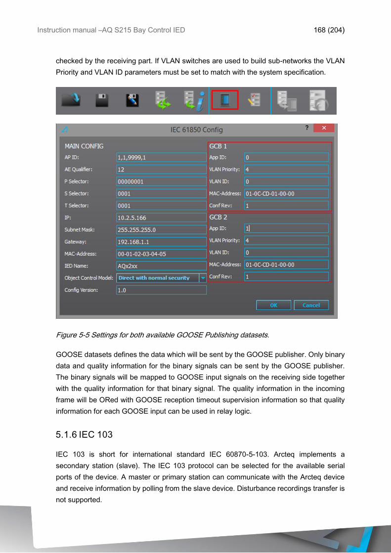
Instruction manual –AQ S215 Bay Control IED 168 (204)
checked by the receiving part. If VLAN switches are used to build sub-networks the VLAN
Priority and VLAN ID parameters must be set to match with the system specification.
Figure 5-5 Settings for both available GOOSE Publishing datasets.
GOOSE datasets defines the data which will be sent by the GOOSE publisher. Only binary
data and quality information for the binary signals can be sent by the GOOSE publisher.
The binary signals will be mapped to GOOSE input signals on the receiving side together
with the quality information for that binary signal. The quality information in the incoming
frame will be ORed with GOOSE reception timeout supervision information so that quality
information for each GOOSE input can be used in relay logic.
5.1.6 IEC 103
IEC 103 is short for international standard IEC 60870-5-103. Arcteq implements a
secondary station (slave). The IEC 103 protocol can be selected for the available serial
ports of the device. A master or primary station can communicate with the Arcteq device
and receive information by polling from the slave device. Disturbance recordings transfer is
not supported.
Instruction manual –AQ S215 Bay Control IED 169 (204)
NOTE: IEC103 map of the relay is found in AQtivate software in Tools IEC103 map once
the configuration file has been loaded.
IEC 103 parameters can be found in the following table.
Parameter Range Description
Slave address [1…254] IEC 103 slave address for
the unit.
Measurement interval [0…60000]ms Interval setting for the
measurements update.
5.1.7 DNP3
DNP3 is a protocol standard which is controlled by the DNP Users Group at www.dnp.org.
The implementation in the AQ2xx series of a DNP3 slave is compliant with DNP3 Subset
Definition Level 2, but contains also functionality of higher levels. For detailed information
see the DNP3 Device Profile document.
DNP3 parameters can be found in following table.
Parameter Range Description
Slave address [1…65519] DNP3 slave address for
the unit.
Master address [1…65519] DNP3 address setting for
allowed master.
Link layer timeout [0…60000]ms Timeout of link layer
Link layer retries [1…20] Number of link layer
retries
Application layer timeout [0…60000]ms Application layer timeout
Application layer
confirmation
[0=No,1=Yes] Application layer
confirmation enable.
Time sync request
interval
[0…60000]ms Request interval for
synchronization.
5.1.8 IEC 101 / 104
Standards IEC 60870-5-101 & IEC 60870-5-104 are closely related. Both are derived from
IEC 60870-5 standard. On the physical layer IEC 101 uses serial communication but IEC
104 uses Ethernet communication.
Instruction manual –AQ S215 Bay Control IED 170 (204)
The IEC 101/104 implementation in AQ2xx series works as a slave in unbalanced mode.
For more detailed information see the IEC101 Profile Checklist document.
IEC101/104 parameters can be found in following table.
Parameter Range Description
Link layer address [1…65535] Link layer address
Link layer address size [1…2] Link layer address size
ASDU address [1…65535] ASDU address
ASDU address size [1…2] ASDU address size
IO address size [1…2] IO address size
IEC104 server enable [0=No,1=Yes] IEC104 enable
IEC104 client IP Client IP address
5.1.9 SPA PROTOCOL
AQ-2xx relay can act as a SPA-slave. SPA can be selected as the communication protocol
into COM B port (in CPU module). If serial RS232 & serial fiber module is available in the
device SPA protocol can be activated for these channels (COM E or F). See the chapter for
construction and installation to see the connections for these modules.
SPAs data transfer rate is 9600bps but it can be also set to 19200bps or 38400bps. As a
slave the relay will send data on demand or by sequenced polling. Available data can be
measurements, circuit breaker states, function starts/trips etc. Full SPA signal map can be
found in AQtivate from ToolsSPA map. Please note that aqs file should be downloaded
from relay first.
The SPA EVENT addresses can be found in Tools Events and logs Event list. This
also requires to open an aqs configuration file of the relay first.
NOTE: SPA map of the relay is found in AQtivate software in Tools SPA map once the
configuration file has been loaded.
5.2 GENERAL IO ANALOG FAULT REGISTERS
In the menu in Communication General IO Analog fault register it is possible to set up
to 12 channels to record the measured value at the time of protection function start or trip.
These values can be read through possibly used communication protocol or locally from
this same menu.
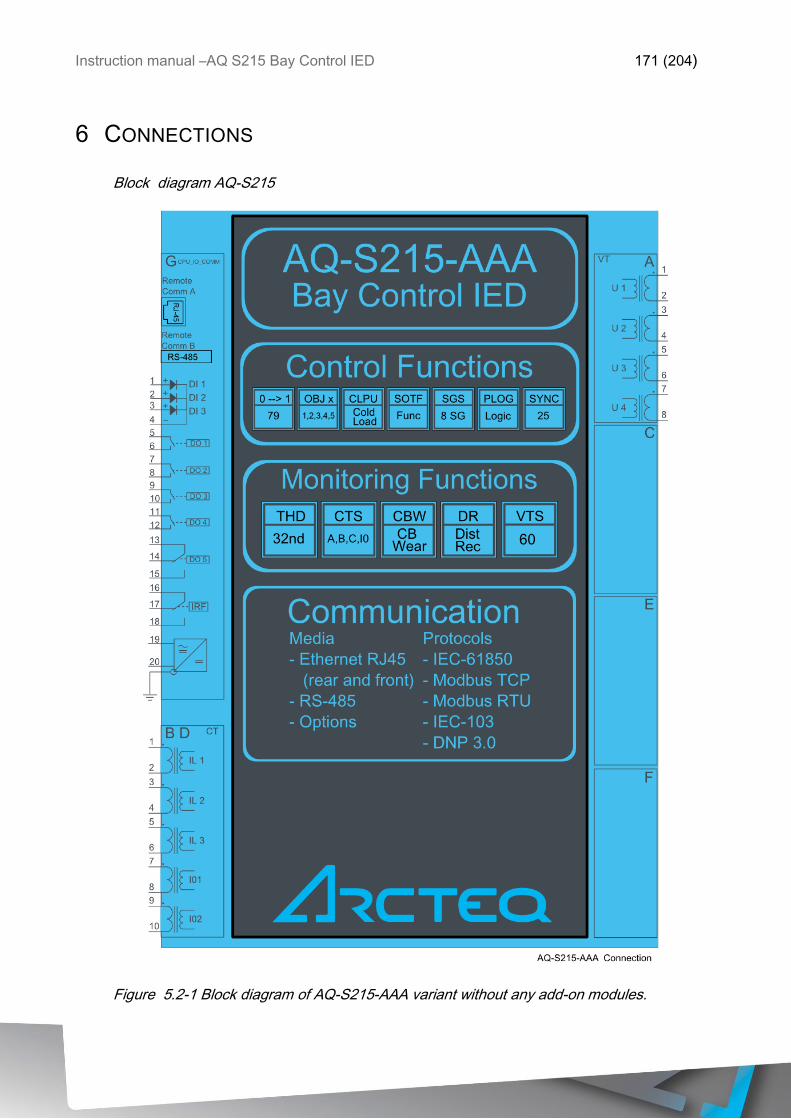
Instruction manual –AQ S215 Bay Control IED 171 (204)
6 CONNECTIONS
Block diagram AQ-S215
Figure 5.2-1 Block diagram of AQ-S215-AAA variant without any add-on modules.
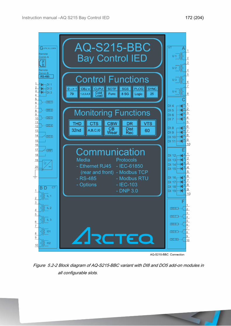
Instruction manual –AQ S215 Bay Control IED 172 (204)
Figure 5.2-2 Block diagram of AQ-S215-BBC variant with DI8 and DO5 add-on modules in
all configurable slots.
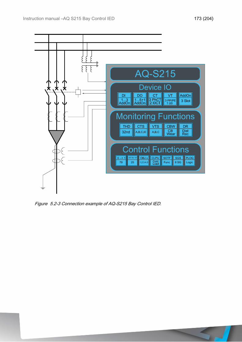
Instruction manual –AQ S215 Bay Control IED 173 (204)
Figure 5.2-3 Connection example of AQ-S215 Bay Control IED.
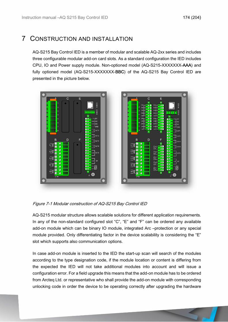
Instruction manual –AQ S215 Bay Control IED 174 (204)
7 CONSTRUCTION AND INSTALLATION
AQ-S215 Bay Control IED is a member of modular and scalable AQ-2xx series and includes
three configurable modular add-on card slots. As a standard configuration the IED includes
CPU, IO and Power supply module. Non-optioned model (AQ-S215-XXXXXXX-AAA) and
fully optioned model (AQ-S215-XXXXXXX-BBC) of the AQ-S215 Bay Control IED are
presented in the picture below.
Figure 7-1 Modular construction of AQ-S215 Bay Control IED
AQ-S215 modular structure allows scalable solutions for different application requirements.
In any of the non-standard configured slot “C”, “E” and “F” can be ordered any available
add-on module which can be binary IO module, integrated Arc –protection or any special
module provided. Only differentiating factor in the device scalability is considering the “E”
slot which supports also communication options.
In case add-on module is inserted to the IED the start-up scan will search of the modules
according to the type designation code, if the module location or content is differing from
the expected the IED will not take additional modules into account and will issue a
configuration error. For a field upgrade this means that the add-on module has to be ordered
from Arcteq Ltd. or representative who shall provide the add-on module with corresponding
unlocking code in order the device to be operating correctly after upgrading the hardware
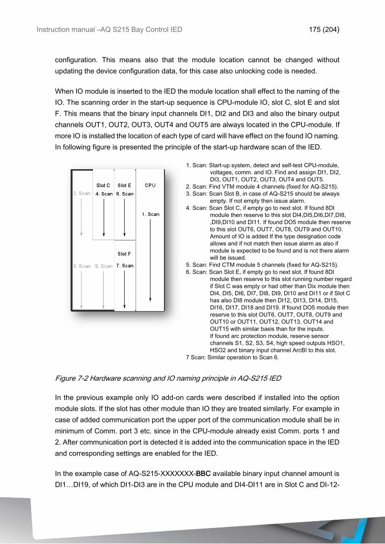
Instruction manual –AQ S215 Bay Control IED 175 (204)
configuration. This means also that the module location cannot be changed without
updating the device configuration data, for this case also unlocking code is needed.
When IO module is inserted to the IED the module location shall effect to the naming of the
IO. The scanning order in the start-up sequence is CPU-module IO, slot C, slot E and slot
F. This means that the binary input channels DI1, DI2 and DI3 and also the binary output
channels OUT1, OUT2, OUT3, OUT4 and OUT5 are always located in the CPU-module. If
more IO is installed the location of each type of card will have effect on the found IO naming.
In following figure is presented the principle of the start-up hardware scan of the IED.
1. Scan: Start-up system, detect and self-test CPU-module,
voltages, comm. and IO. Find and assign DI1, DI2,
DI3, OUT1, OUT2, OUT3, OUT4 and OUT5.
2. Scan: Find VTM module 4 channels (fixed for AQ-S215).
3. Scan: Scan Slot B, in case of AQ-S215 should be always
empty. If not empty then issue alarm.
4. Scan: Scan Slot C, if empty go to next slot. If found 8DI
module then reserve to this slot DI4,DI5,DI6,DI7,DI8,
,DI9,DI10 and DI11. If found DO5 module then reserve
to this slot OUT6, OUT7, OUT8, OUT9 and OUT10.
Amount of IO is added If the type designation code
allows and if not match then issue alarm as also if
module is expected to be found and is not there alarm
will be issued.
5. Scan: Find CTM module 5 channels (fixed for AQ-S215).
6. Scan: Scan Slot E, if empty go to next slot. If found 8DI
module then reserve to this slot running number regard
if Slot C was empty or had other than Dix module then
DI4, DI5, DI6, DI7, DI8, DI9, DI10 and DI11 or if Slot C
has also DI8 module then DI12, DI13, DI14, DI15,
DI16, DI17, DI18 and DI19. If found DO5 module then
reserve to this slot OUT6, OUT7, OUT8, OUT9 and
OUT10 or OUT11, OUT12, OUT13, OUT14 and
OUT15 with similar basis than for the inputs.
If found arc protection module, reserve sensor
channels S1, S2, S3, S4, high speed outputs HSO1,
HSO2 and binary input channel ArcBI to this slot.
7 Scan: Similar operation to Scan 6.
Figure 7-2 Hardware scanning and IO naming principle in AQ-S215 IED
In the previous example only IO add-on cards were described if installed into the option
module slots. If the slot has other module than IO they are treated similarly. For example in
case of added communication port the upper port of the communication module shall be in
minimum of Comm. port 3 etc. since in the CPU-module already exist Comm. ports 1 and
2. After communication port is detected it is added into the communication space in the IED
and corresponding settings are enabled for the IED.
In the example case of AQ-S215-XXXXXXX-BBC available binary input channel amount is
DI1…DI19, of which DI1-DI3 are in the CPU module and DI4-DI11 are in Slot C and DI-12-

Instruction manual –AQ S215 Bay Control IED 176 (204)
19 are in slot E. Available binary output channels are DO1…DO10, from which DO1-DO5
are in the CPU module and DO6-DO10 are in slot F. If the configuration should differ from
this example the same principle is always applied into the IED.
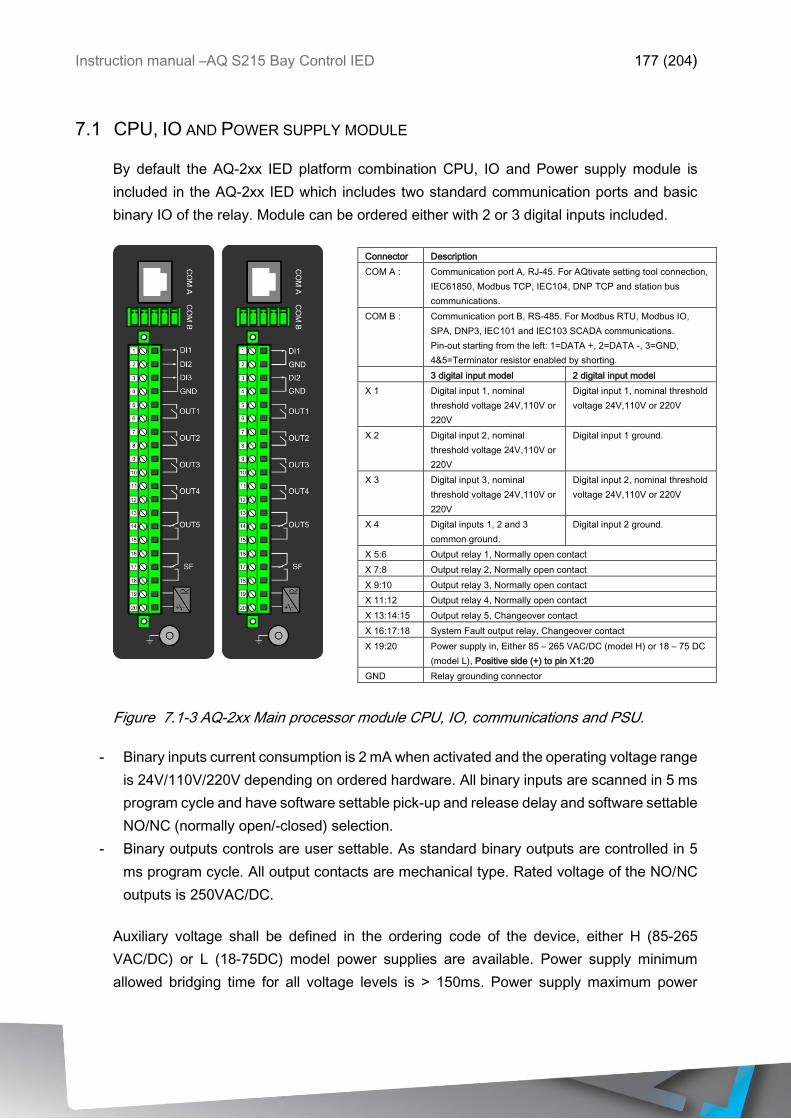
Instruction manual –AQ S215 Bay Control IED 177 (204)
7.1 CPU, IO AND POWER SUPPLY MODULE
By default the AQ-2xx IED platform combination CPU, IO and Power supply module is
included in the AQ-2xx IED which includes two standard communication ports and basic
binary IO of the relay. Module can be ordered either with 2 or 3 digital inputs included.
Figure 7.1-3 AQ-2xx Main processor module CPU, IO, communications and PSU.
- Binary inputs current consumption is 2 mA when activated and the operating voltage range
is 24V/110V/220V depending on ordered hardware. All binary inputs are scanned in 5 ms
program cycle and have software settable pick-up and release delay and software settable
NO/NC (normally open/-closed) selection.
- Binary outputs controls are user settable. As standard binary outputs are controlled in 5
ms program cycle. All output contacts are mechanical type. Rated voltage of the NO/NC
outputs is 250VAC/DC.
Auxiliary voltage shall be defined in the ordering code of the device, either H (85-265
VAC/DC) or L (18-75DC) model power supplies are available. Power supply minimum
allowed bridging time for all voltage levels is > 150ms. Power supply maximum power
Connector Description
COM A : Communication port A, RJ-45. For AQtivate setting tool connection,
IEC61850, Modbus TCP, IEC104, DNP TCP and station bus
communications.
COM B : Communication port B, RS-485. For Modbus RTU, Modbus IO,
SPA, DNP3, IEC101 and IEC103 SCADA communications.
Pin-out starting from the left: 1=DATA +, 2=DATA -, 3=GND,
4&5=Terminator resistor enabled by shorting.
3 digital input model 2 digital input model
X 1 Digital input 1, nominal
threshold voltage 24V,110V or
220V
Digital input 1, nominal threshold
voltage 24V,110V or 220V
X 2 Digital input 2, nominal
threshold voltage 24V,110V or
220V
Digital input 1 ground.
X 3 Digital input 3, nominal
threshold voltage 24V,110V or
220V
Digital input 2, nominal threshold
voltage 24V,110V or 220V
X 4 Digital inputs 1, 2 and 3
common ground.
Digital input 2 ground.
X 5:6 Output relay 1, Normally open contact
X 7:8 Output relay 2, Normally open contact
X 9:10 Output relay 3, Normally open contact
X 11:12 Output relay 4, Normally open contact
X 13:14:15 Output relay 5, Changeover contact
X 16:17:18 System Fault output relay, Changeover contact
X 19:20 Power supply in, Either 85 – 265 VAC/DC (model H) or 18 – 75 DC
(model L), Positive side (+) to pin X1:20
GND Relay grounding connector

Instruction manual –AQ S215 Bay Control IED 178 (204)
consumption is 15W max. Power supply allows DC ripple of <15 % and start-up time of
power supply is < 5ms. Further details refer to the “Technical data” section of this document.
7.1.1 SCANNING CYCLE OF THE DIGITAL INPUT
Binary inputs are scanned in 5 millisecond cycle. This makes the state of input to be updated
between 0…5 milliseconds. When input is used internally in IED (group change or logic) it
takes additional 0…5 milliseconds to operate. So in theory when binary input is used for
group control or similar it takes 0…10 milliseconds to change the group. In practice the
delay is between 2…8 milliseconds about 95% of the time. In case the binary input is
connected directly to binary output (T1…Tx) it takes additional third 5 millisecond round.
When binary input is controlling internally binary output it takes 0…15 milliseconds in theory
and 2…13 milliseconds in practice. This delay excludes the mechanical delay of the relay.
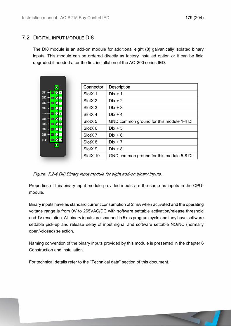
Instruction manual –AQ S215 Bay Control IED 179 (204)
7.2 DIGITAL INPUT MODULE DI8
The DI8 module is an add-on module for additional eight (8) galvanically isolated binary
inputs. This module can be ordered directly as factory installed option or it can be field
upgraded if needed after the first installation of the AQ-200 series IED.
Connector Description
SlotX 1 DIx + 1
SlotX 2 DIx + 2
SlotX 3 DIx + 3
SlotX 4 DIx + 4
SlotX 5 GND common ground for this module 1-4 DI
SlotX 6 DIx + 5
SlotX 7 DIx + 6
SlotX 8 DIx + 7
SlotX 9 DIx + 8
SlotX 10 GND common ground for this module 5-8 DI
Figure 7.2-4 DI8 Binary input module for eight add-on binary inputs.
Properties of this binary input module provided inputs are the same as inputs in the CPU-
module.
Binary inputs have as standard current consumption of 2 mA when activated and the operating
voltage range is from 0V to 265VAC/DC with software settable activation/release threshold
and 1V resolution. All binary inputs are scanned in 5 ms program cycle and they have software
settable pick-up and release delay of input signal and software settable NO/NC (normally
open/-closed) selection.
Naming convention of the binary inputs provided by this module is presented in the chapter 6
Construction and installation.
For technical details refer to the “Technical data” section of this document.
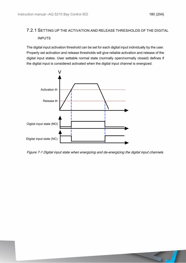
Instruction manual –AQ S215 Bay Control IED 180 (204)
7.2.1 SETTING UP THE ACTIVATION AND RELEASE THRESHOLDS OF THE DIGITAL
INPUTS
The digital input activation threshold can be set for each digital input individually by the user.
Properly set activation and release thresholds will give reliable activation and release of the
digital input states. User settable normal state (normally open/normally closed) defines if
the digital input is considered activated when the digital input channel is energized.
Figure 7-1 Digital input state when energizing and de-energizing the digital input channels.
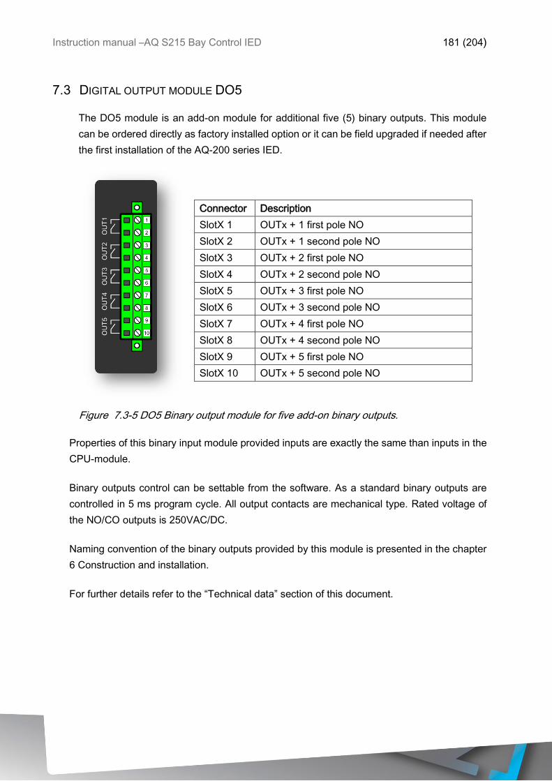
Instruction manual –AQ S215 Bay Control IED 181 (204)
7.3 DIGITAL OUTPUT MODULE DO5
The DO5 module is an add-on module for additional five (5) binary outputs. This module
can be ordered directly as factory installed option or it can be field upgraded if needed after
the first installation of the AQ-200 series IED.
Connector Description
SlotX 1 OUTx + 1 first pole NO
SlotX 2 OUTx + 1 second pole NO
SlotX 3 OUTx + 2 first pole NO
SlotX 4 OUTx + 2 second pole NO
SlotX 5 OUTx + 3 first pole NO
SlotX 6 OUTx + 3 second pole NO
SlotX 7 OUTx + 4 first pole NO
SlotX 8 OUTx + 4 second pole NO
SlotX 9 OUTx + 5 first pole NO
SlotX 10 OUTx + 5 second pole NO
Figure 7.3-5 DO5 Binary output module for five add-on binary outputs.
Properties of this binary input module provided inputs are exactly the same than inputs in the
CPU-module.
Binary outputs control can be settable from the software. As a standard binary outputs are
controlled in 5 ms program cycle. All output contacts are mechanical type. Rated voltage of
the NO/CO outputs is 250VAC/DC.
Naming convention of the binary outputs provided by this module is presented in the chapter
6 Construction and installation.
For further details refer to the “Technical data” section of this document.
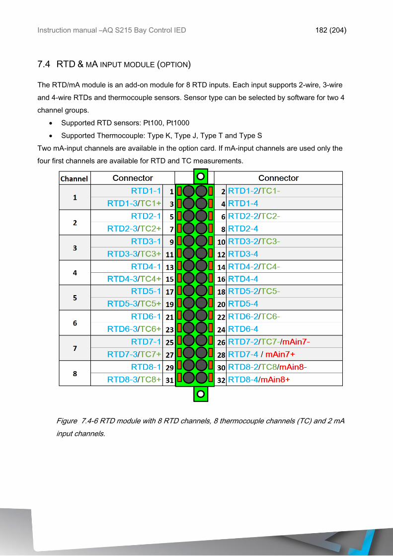
Instruction manual –AQ S215 Bay Control IED 182 (204)
7.4 RTD & MA INPUT MODULE (OPTION)
The RTD/mA module is an add-on module for 8 RTD inputs. Each input supports 2-wire, 3-wire
and 4-wire RTDs and thermocouple sensors. Sensor type can be selected by software for two 4
channel groups.
• Supported RTD sensors: Pt100, Pt1000
• Supported Thermocouple: Type K, Type J, Type T and Type S
Two mA-input channels are available in the option card. If mA-input channels are used only the
four first channels are available for RTD and TC measurements.
Figure 7.4-6 RTD module with 8 RTD channels, 8 thermocouple channels (TC) and 2 mA
input channels.
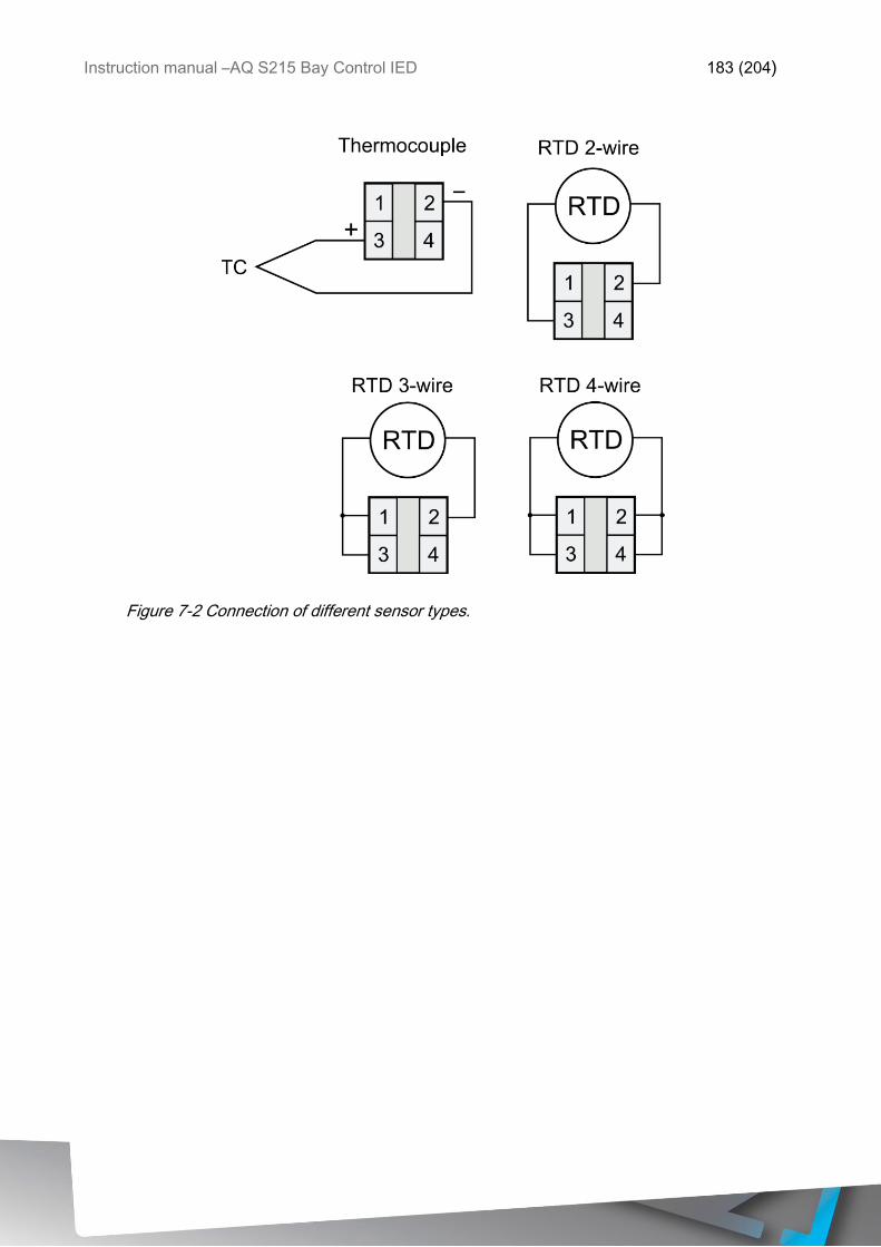
Instruction manual –AQ S215 Bay Control IED 183 (204)
Figure 7-2 Connection of different sensor types.
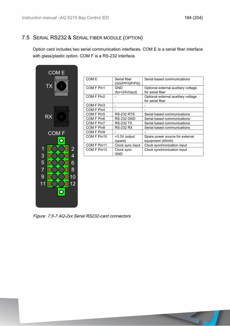
Instruction manual –AQ S215 Bay Control IED 184 (204)
7.5 SERIAL RS232 & SERIAL FIBER MODULE (OPTION)
Option card includes two serial communication interfaces. COM E is a serial fiber interface
with glass/plastic option. COM F is a RS-232 interface.
COM E Serial fiber
(GG/PP/GP/PG)
Serial based communications
COM F Pin1 GND
(for+24Vinput)
Optional external auxiliary voltage
for serial fiber
COM F Pin2 - Optional external auxiliary voltage
for serial fiber
COM F Pin3 - -
COM F Pin4 - -
COM F Pin5 RS-232 RTS Serial based communications
COM F Pin6 RS-232 GND Serial based communications
COM F Pin7 RS-232 TX Serial based communications
COM F Pin8 RS-232 RX Serial based communications
COM F Pin9 - -
COM F Pin10 +3.3V output
(spare)
Spare power source for external
equipment (45mA)
COM F Pin11 Clock sync input Clock synchronization input
COM F Pin12 Clock sync
GND
Clock synchronization input
Figure 7.5-7 AQ-2xx Serial RS232-card connectors
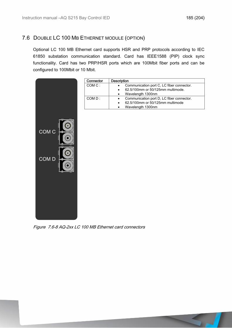
Instruction manual –AQ S215 Bay Control IED 185 (204)
7.6 DOUBLE LC 100 MB ETHERNET MODULE (OPTION)
Optional LC 100 MB Ethernet card supports HSR and PRP protocols according to IEC
61850 substation communication standard. Card has IEEE1588 (PIP) clock sync
functionality. Card has two PRP/HSR ports which are 100Mbit fiber ports and can be
configured to 100Mbit or 10 Mbit.
Connector Description
COM C : • Communication port C, LC fiber connector.
• 62.5/100mm or 50/125mm multimode.
• Wavelength 1300nm
COM D : • Communication port D, LC fiber connector.
• 62.5/100mm or 50/125mm multimode
• Wavelength 1300nm
Figure 7.6-8 AQ-2xx LC 100 MB Ethernet card connectors
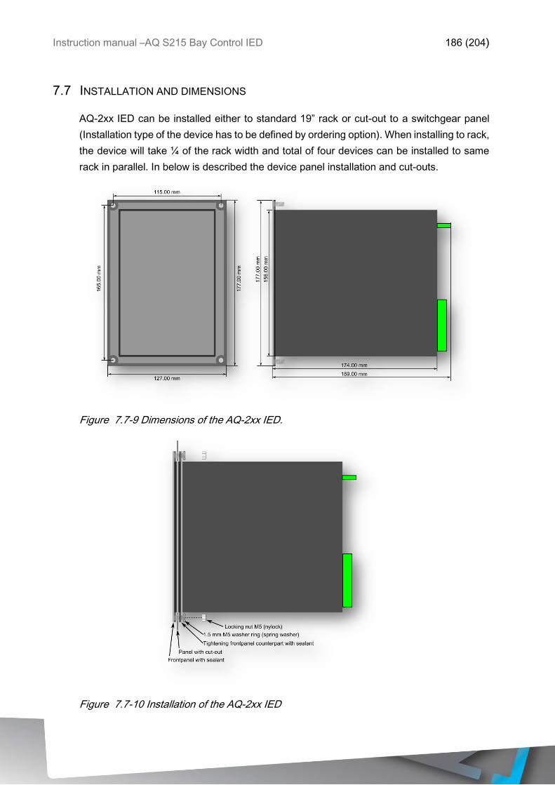
Instruction manual –AQ S215 Bay Control IED 186 (204)
7.7 INSTALLATION AND DIMENSIONS
AQ-2xx IED can be installed either to standard 19” rack or cut-out to a switchgear panel
(Installation type of the device has to be defined by ordering option). When installing to rack,
the device will take ¼ of the rack width and total of four devices can be installed to same
rack in parallel. In below is described the device panel installation and cut-outs.
Figure 7.7-9 Dimensions of the AQ-2xx IED.
Figure 7.7-10 Installation of the AQ-2xx IED
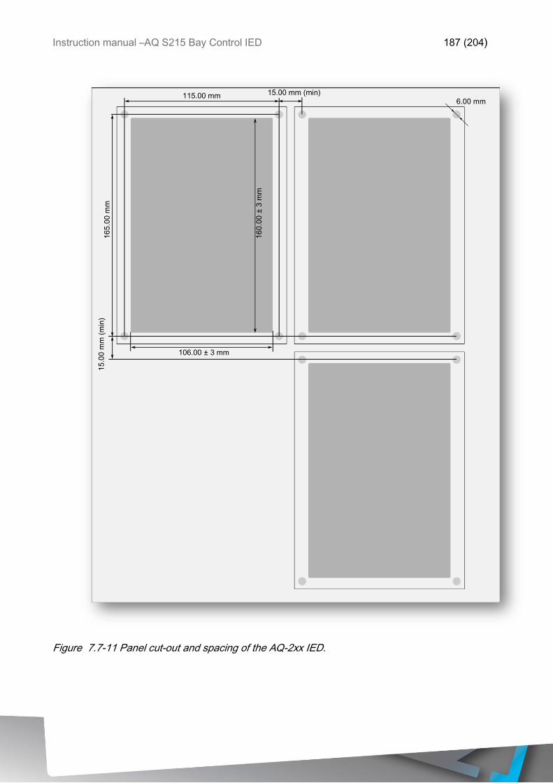
Instruction manual –AQ S215 Bay Control IED 187 (204)
Figure 7.7-11 Panel cut-out and spacing of the AQ-2xx IED.
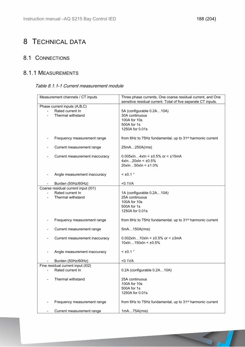
Instruction manual –AQ S215 Bay Control IED 188 (204)
8 TECHNICAL DATA
8.1 CONNECTIONS
8.1.1 MEASUREMENTS
Table 8.1.1-1 Current measurement module
Measurement channels / CT inputs Three phase currents, One coarse residual current, and One
sensitive residual current. Total of five separate CT inputs.
Phase current inputs (A,B,C)
- Rated current In
- Thermal withstand
- Frequency measurement range
- Current measurement range
- Current measurement inaccuracy
- Angle measurement inaccuracy
- Burden (50Hz/60Hz)
5A (configurable 0.2A…10A)
30A continuous
100A for 10s
500A for 1s
1250A for 0.01s
from 6Hz to 75Hz fundamental, up to 31st harmonic current
25mA…250A(rms)
0.005xIn…4xIn < ±0.5% or < ±15mA
4xIn…20xIn < ±0.5%
20xIn…50xIn < ±1.0%
< ±0.1 °
<0.1VA
Coarse residual current input (I01)
- Rated current In
- Thermal withstand
- Frequency measurement range
- Current measurement range
- Current measurement inaccuracy
- Angle measurement inaccuracy
- Burden (50Hz/60Hz)
1A (configurable 0.2A…10A)
25A continuous
100A for 10s
500A for 1s
1250A for 0.01s
from 6Hz to 75Hz fundamental, up to 31st harmonic current
5mA…150A(rms)
0.002xIn…10xIn < ±0.5% or < ±3mA
10xIn…150xIn < ±0.5%
< ±0.1 °
<0.1VA
Fine residual current input (I02)
- Rated current In
- Thermal withstand
- Frequency measurement range
- Current measurement range
0.2A (configurable 0.2A…10A)
25A continuous
100A for 10s
500A for 1s
1250A for 0.01s
from 6Hz to 75Hz fundamental, up to 31st harmonic current
1mA…75A(rms)
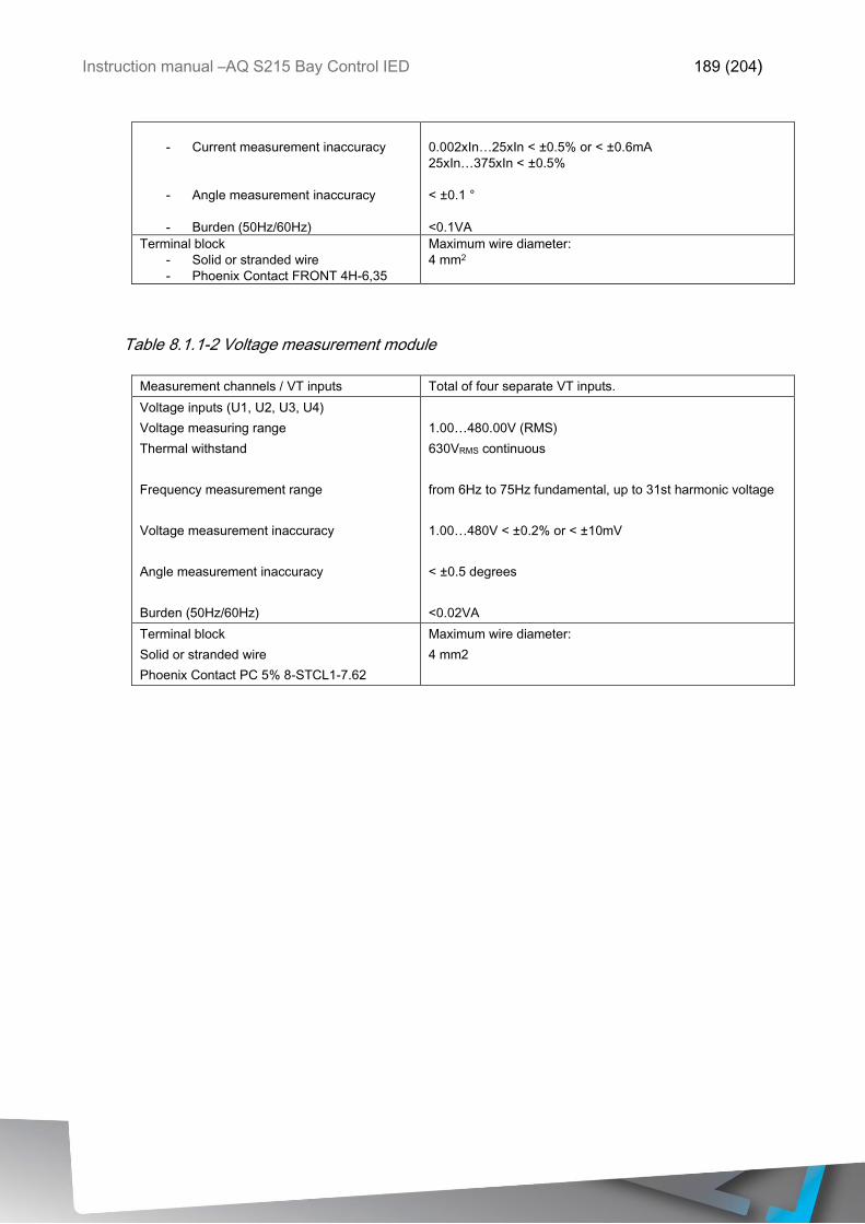
Instruction manual –AQ S215 Bay Control IED 189 (204)
- Current measurement inaccuracy
- Angle measurement inaccuracy
- Burden (50Hz/60Hz)
0.002xIn…25xIn < ±0.5% or < ±0.6mA
25xIn…375xIn < ±0.5%
< ±0.1 °
<0.1VA
Terminal block
- Solid or stranded wire
- Phoenix Contact FRONT 4H-6,35
Maximum wire diameter:
4 mm2
Table 8.1.1-2 Voltage measurement module
Measurement channels / VT inputs Total of four separate VT inputs.
Voltage inputs (U1, U2, U3, U4)
Voltage measuring range
Thermal withstand
Frequency measurement range
Voltage measurement inaccuracy
Angle measurement inaccuracy
Burden (50Hz/60Hz)
1.00…480.00V (RMS)
630VRMS continuous
from 6Hz to 75Hz fundamental, up to 31st harmonic voltage
1.00…480V < ±0.2% or < ±10mV
< ±0.5 degrees
<0.02VA
Terminal block
Solid or stranded wire
Phoenix Contact PC 5% 8-STCL1-7.62
Maximum wire diameter:
4 mm2
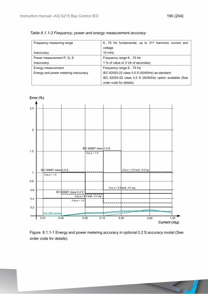
Instruction manual –AQ S215 Bay Control IED 190 (204)
Table 8.1.1-3 Frequency, power and energy measurement accuracy
Frequency measuring range
Inaccuracy
6…75 Hz fundamental, up to 31st harmonic current and
voltage
10 mHz
Power measurement P, Q, S
Inaccuracy
Frequency range 6…75 Hz
1 % of value or 3 VA of secondary
Energy measurement
Energy and power metering inaccuracy
Frequency range 6…75 Hz
IEC 62053-22 class 0.5 S (50/60Hz) as standard
IEC 62053-22 class 0.2 S (50/60Hz) option available (See
order code for details)
Figure 8.1.1-1 Energy and power metering accuracy in optional 0.2 S accuracy model (See
order code for details).
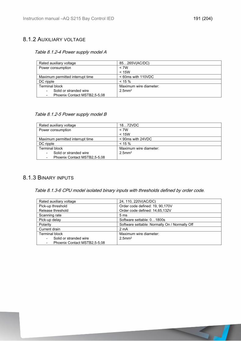
Instruction manual –AQ S215 Bay Control IED 191 (204)
8.1.2 AUXILIARY VOLTAGE
Table 8.1.2-4 Power supply model A
Rated auxiliary voltage 85…265V(AC/DC)
Power consumption < 7W
< 15W
Maximum permitted interrupt time < 60ms with 110VDC
DC ripple < 15 %
Terminal block
- Solid or stranded wire
- Phoenix Contact MSTB2,5-5,08
Maximum wire diameter:
2.5mm2
Table 8.1.2-5 Power supply model B
Rated auxiliary voltage 18…72VDC
Power consumption < 7W
< 15W
Maximum permitted interrupt time < 90ms with 24VDC
DC ripple < 15 %
Terminal block
- Solid or stranded wire
- Phoenix Contact MSTB2,5-5,08
Maximum wire diameter:
2.5mm2
8.1.3 BINARY INPUTS
Table 8.1.3-6 CPU model isolated binary inputs with thresholds defined by order code.
Rated auxiliary voltage 24, 110, 220V(AC/DC)
Pick-up threshold
Release threshold
Order code defined: 19, 90,170V
Order code defined: 14,65,132V
Scanning rate 5 ms
Pick-up delay Software settable: 0…1800s
Polarity Software settable: Normally On / Normally Off
Current drain 2 mA
Terminal block
- Solid or stranded wire
- Phoenix Contact MSTB2,5-5,08
Maximum wire diameter:
2.5mm2
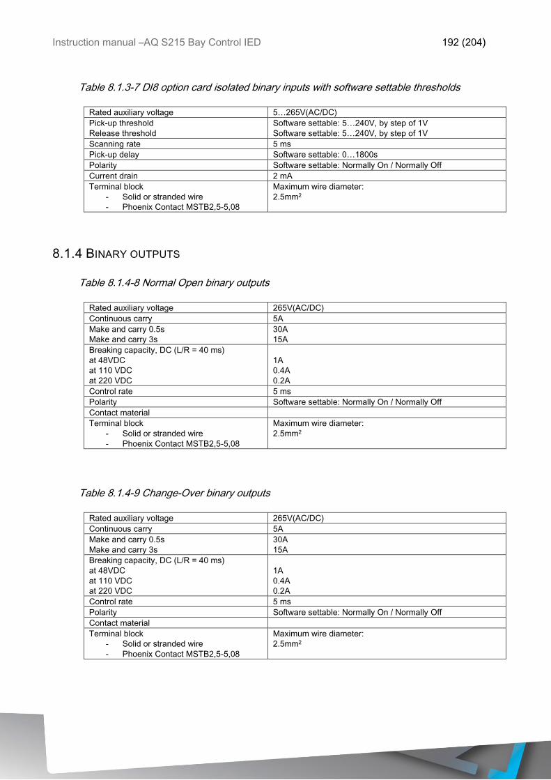
Instruction manual –AQ S215 Bay Control IED 192 (204)
Table 8.1.3-7 DI8 option card isolated binary inputs with software settable thresholds
Rated auxiliary voltage 5…265V(AC/DC)
Pick-up threshold
Release threshold
Software settable: 5…240V, by step of 1V
Software settable: 5…240V, by step of 1V
Scanning rate 5 ms
Pick-up delay Software settable: 0…1800s
Polarity Software settable: Normally On / Normally Off
Current drain 2 mA
Terminal block
- Solid or stranded wire
- Phoenix Contact MSTB2,5-5,08
Maximum wire diameter:
2.5mm2
8.1.4 BINARY OUTPUTS
Table 8.1.4-8 Normal Open binary outputs
Rated auxiliary voltage 265V(AC/DC)
Continuous carry 5A
Make and carry 0.5s
Make and carry 3s
30A
15A
Breaking capacity, DC (L/R = 40 ms)
at 48VDC
at 110 VDC
at 220 VDC
1A
0.4A
0.2A
Control rate 5 ms
Polarity Software settable: Normally On / Normally Off
Contact material
Terminal block
- Solid or stranded wire
- Phoenix Contact MSTB2,5-5,08
Maximum wire diameter:
2.5mm2
Table 8.1.4-9 Change-Over binary outputs
Rated auxiliary voltage 265V(AC/DC)
Continuous carry 5A
Make and carry 0.5s
Make and carry 3s
30A
15A
Breaking capacity, DC (L/R = 40 ms)
at 48VDC
at 110 VDC
at 220 VDC
1A
0.4A
0.2A
Control rate 5 ms
Polarity Software settable: Normally On / Normally Off
Contact material
Terminal block
- Solid or stranded wire
- Phoenix Contact MSTB2,5-5,08
Maximum wire diameter:
2.5mm2
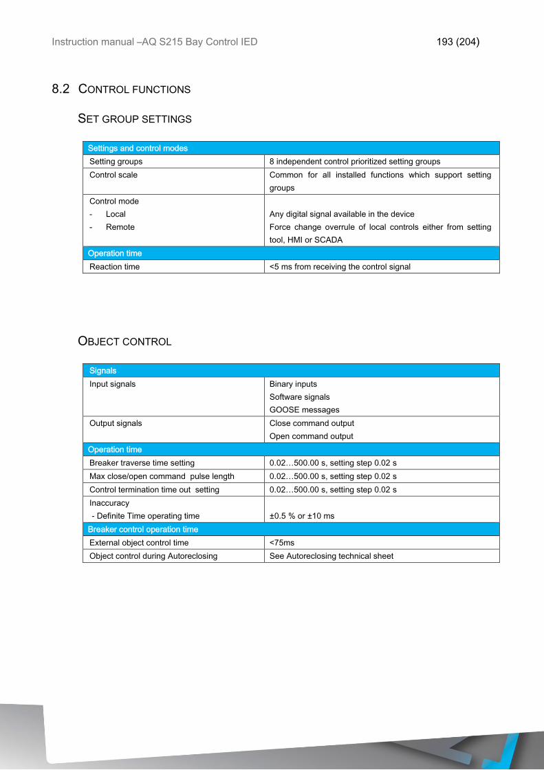
Instruction manual –AQ S215 Bay Control IED 193 (204)
8.2 CONTROL FUNCTIONS
SET GROUP SETTINGS
Settings and control modes
Setting groups 8 independent control prioritized setting groups
Control scale Common for all installed functions which support setting
groups
Control mode
- Local
- Remote
Any digital signal available in the device
Force change overrule of local controls either from setting
tool, HMI or SCADA
Operation time
Reaction time <5 ms from receiving the control signal
OBJECT CONTROL
Signals
Input signals Binary inputs
Software signals
GOOSE messages
Output signals Close command output
Open command output
Operation time
Breaker traverse time setting 0.02…500.00 s, setting step 0.02 s
Max close/open command pulse length 0.02…500.00 s, setting step 0.02 s
Control termination time out setting 0.02…500.00 s, setting step 0.02 s
Inaccuracy
- Definite Time operating time
±0.5 % or ±10 ms
Breaker control operation time
External object control time <75ms
Object control during Autoreclosing See Autoreclosing technical sheet
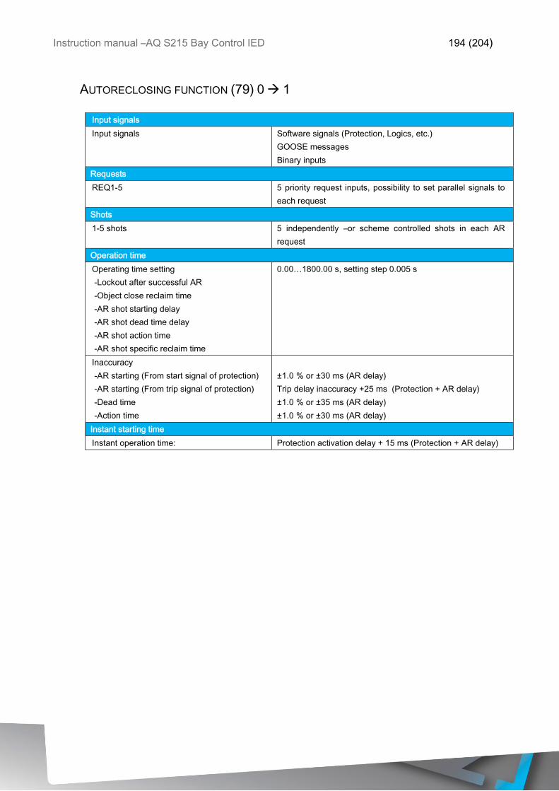
Instruction manual –AQ S215 Bay Control IED 194 (204)
AUTORECLOSING FUNCTION (79) 0 1
Input signals
Input signals Software signals (Protection, Logics, etc.)
GOOSE messages
Binary inputs
Requests
REQ1-5 5 priority request inputs, possibility to set parallel signals to
each request
Shots
1-5 shots 5 independently –or scheme controlled shots in each AR
request
Operation time
Operating time setting
-Lockout after successful AR
-Object close reclaim time
-AR shot starting delay
-AR shot dead time delay
-AR shot action time
-AR shot specific reclaim time
0.00…1800.00 s, setting step 0.005 s
Inaccuracy
-AR starting (From start signal of protection)
-AR starting (From trip signal of protection)
-Dead time
-Action time
±1.0 % or ±30 ms (AR delay)
Trip delay inaccuracy +25 ms (Protection + AR delay)
±1.0 % or ±35 ms (AR delay)
±1.0 % or ±30 ms (AR delay)
Instant starting time
Instant operation time: Protection activation delay + 15 ms (Protection + AR delay)
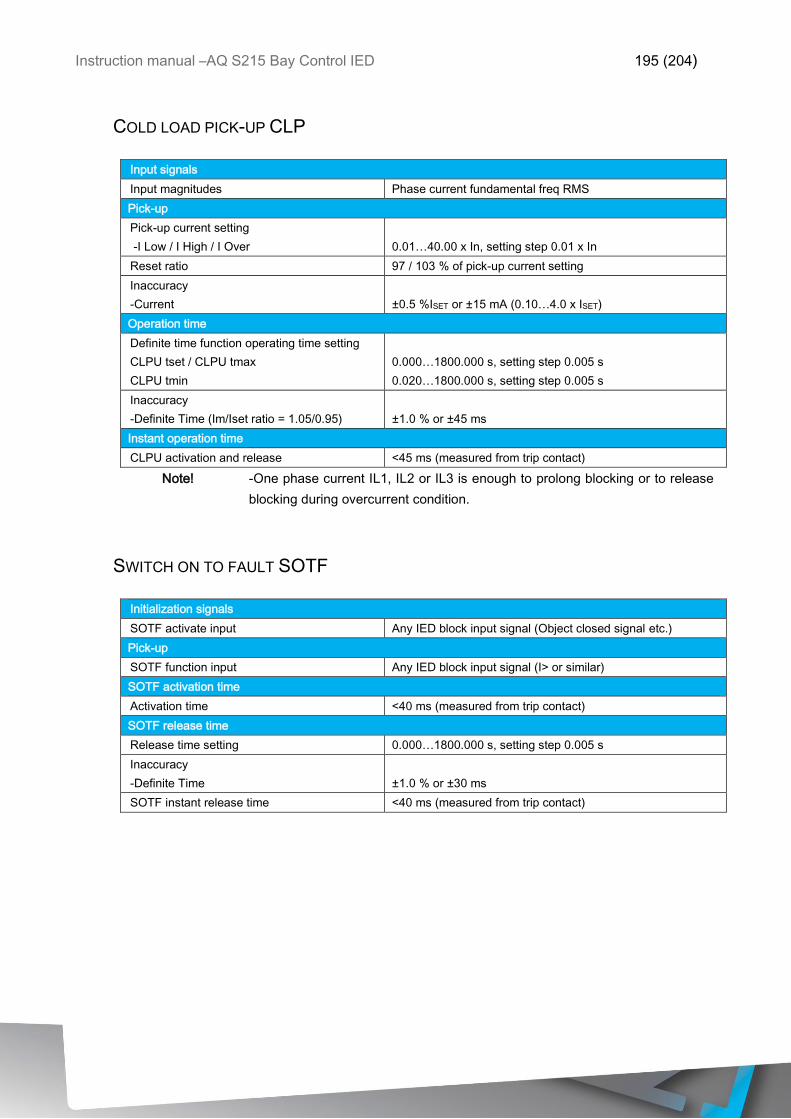
Instruction manual –AQ S215 Bay Control IED 195 (204)
COLD LOAD PICK-UP CLP
Input signals
Input magnitudes Phase current fundamental freq RMS
Pick-up
Pick-up current setting
-I Low / I High / I Over
0.01…40.00 x In, setting step 0.01 x In
Reset ratio 97 / 103 % of pick-up current setting
Inaccuracy
-Current
±0.5 %ISET or ±15 mA (0.10…4.0 x ISET)
Operation time
Definite time function operating time setting
CLPU tset / CLPU tmax
CLPU tmin
0.000…1800.000 s, setting step 0.005 s
0.020…1800.000 s, setting step 0.005 s
Inaccuracy
-Definite Time (Im/Iset ratio = 1.05/0.95)
±1.0 % or ±45 ms
Instant operation time
CLPU activation and release <45 ms (measured from trip contact)
Note! -One phase current IL1, IL2 or IL3 is enough to prolong blocking or to release
blocking during overcurrent condition.
SWITCH ON TO FAULT SOTF
Initialization signals
SOTF activate input Any IED block input signal (Object closed signal etc.)
Pick-up
SOTF function input Any IED block input signal (I> or similar)
SOTF activation time
Activation time <40 ms (measured from trip contact)
SOTF release time
Release time setting 0.000…1800.000 s, setting step 0.005 s
Inaccuracy
-Definite Time
±1.0 % or ±30 ms
SOTF instant release time <40 ms (measured from trip contact)
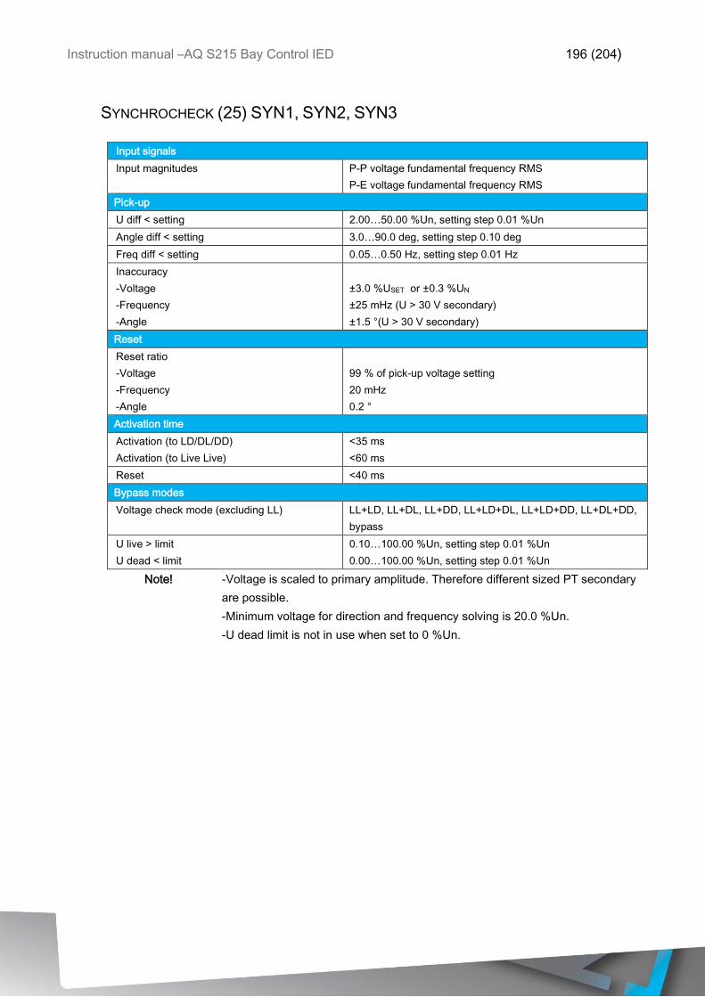
Instruction manual –AQ S215 Bay Control IED 196 (204)
SYNCHROCHECK (25) SYN1, SYN2, SYN3
Input signals
Input magnitudes P-P voltage fundamental frequency RMS
P-E voltage fundamental frequency RMS
Pick-up
U diff < setting 2.00…50.00 %Un, setting step 0.01 %Un
Angle diff < setting 3.0…90.0 deg, setting step 0.10 deg
Freq diff < setting 0.05…0.50 Hz, setting step 0.01 Hz
Inaccuracy
-Voltage
-Frequency
-Angle
±3.0 %USET or ±0.3 %UN
±25 mHz (U > 30 V secondary)
±1.5 °(U > 30 V secondary)
Reset
Reset ratio
-Voltage
-Frequency
-Angle
99 % of pick-up voltage setting
20 mHz
0.2 °
Activation time
Activation (to LD/DL/DD)
Activation (to Live Live)
<35 ms
<60 ms
Reset <40 ms
Bypass modes
Voltage check mode (excluding LL) LL+LD, LL+DL, LL+DD, LL+LD+DL, LL+LD+DD, LL+DL+DD,
bypass
U live > limit
U dead < limit
0.10…100.00 %Un, setting step 0.01 %Un
0.00…100.00 %Un, setting step 0.01 %Un
Note! -Voltage is scaled to primary amplitude. Therefore different sized PT secondary
are possible.
-Minimum voltage for direction and frequency solving is 20.0 %Un.
-U dead limit is not in use when set to 0 %Un.
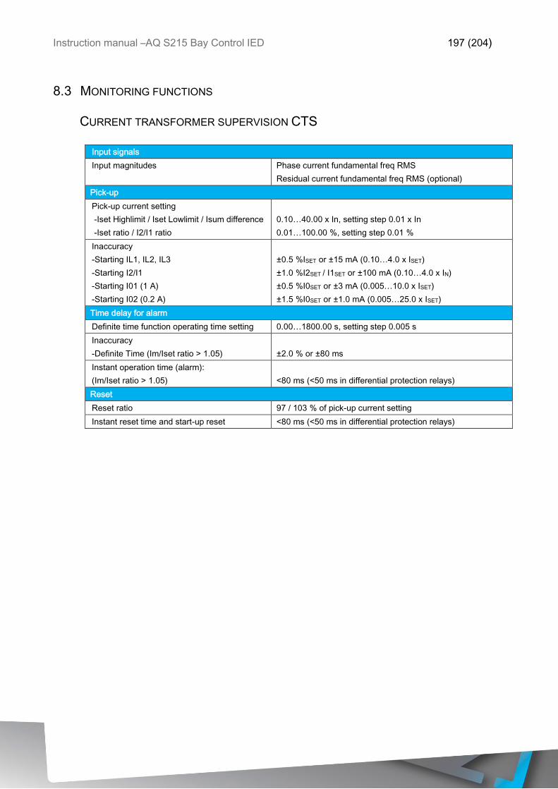
Instruction manual –AQ S215 Bay Control IED 197 (204)
8.3 MONITORING FUNCTIONS
CURRENT TRANSFORMER SUPERVISION CTS
Input signals
Input magnitudes Phase current fundamental freq RMS
Residual current fundamental freq RMS (optional)
Pick-up
Pick-up current setting
-Iset Highlimit / Iset Lowlimit / Isum difference
-Iset ratio / I2/I1 ratio
0.10…40.00 x In, setting step 0.01 x In
0.01…100.00 %, setting step 0.01 %
Inaccuracy
-Starting IL1, IL2, IL3
-Starting I2/I1
-Starting I01 (1 A)
-Starting I02 (0.2 A)
±0.5 %ISET or ±15 mA (0.10…4.0 x ISET)
±1.0 %I2SET / I1SET or ±100 mA (0.10…4.0 x IN)
±0.5 %I0SET or ±3 mA (0.005…10.0 x ISET)
±1.5 %I0SET or ±1.0 mA (0.005…25.0 x ISET)
Time delay for alarm
Definite time function operating time setting 0.00…1800.00 s, setting step 0.005 s
Inaccuracy
-Definite Time (Im/Iset ratio > 1.05)
±2.0 % or ±80 ms
Instant operation time (alarm):
(Im/Iset ratio > 1.05)
<80 ms (<50 ms in differential protection relays)
Reset
Reset ratio 97 / 103 % of pick-up current setting
Instant reset time and start-up reset <80 ms (<50 ms in differential protection relays)
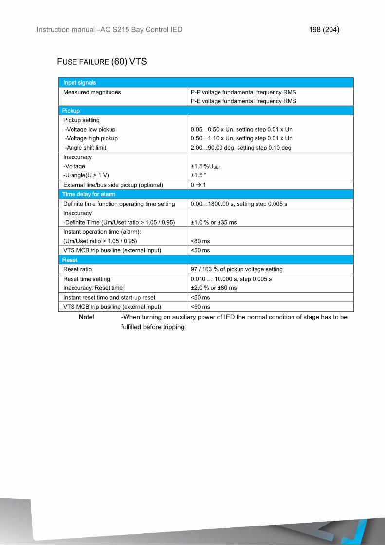
Instruction manual –AQ S215 Bay Control IED 198 (204)
FUSE FAILURE (60) VTS
Input signals
Measured magnitudes P-P voltage fundamental frequency RMS
P-E voltage fundamental frequency RMS
Pickup
Pickup setting
-Voltage low pickup
-Voltage high pickup
-Angle shift limit
0.05…0.50 x Un, setting step 0.01 x Un
0.50…1.10 x Un, setting step 0.01 x Un
2.00…90.00 deg, setting step 0.10 deg
Inaccuracy
-Voltage
-U angle(U > 1 V)
±1.5 %USET
±1.5 °
External line/bus side pickup (optional) 0 1
Time delay for alarm
Definite time function operating time setting 0.00…1800.00 s, setting step 0.005 s
Inaccuracy
-Definite Time (Um/Uset ratio > 1.05 / 0.95)
±1.0 % or ±35 ms
Instant operation time (alarm):
(Um/Uset ratio > 1.05 / 0.95)
<80 ms
VTS MCB trip bus/line (external input) <50 ms
Reset
Reset ratio 97 / 103 % of pickup voltage setting
Reset time setting
Inaccuracy: Reset time
0.010 … 10.000 s, step 0.005 s
±2.0 % or ±80 ms
Instant reset time and start-up reset <50 ms
VTS MCB trip bus/line (external input) <50 ms
Note! -When turning on auxiliary power of IED the normal condition of stage has to be
fulfilled before tripping.
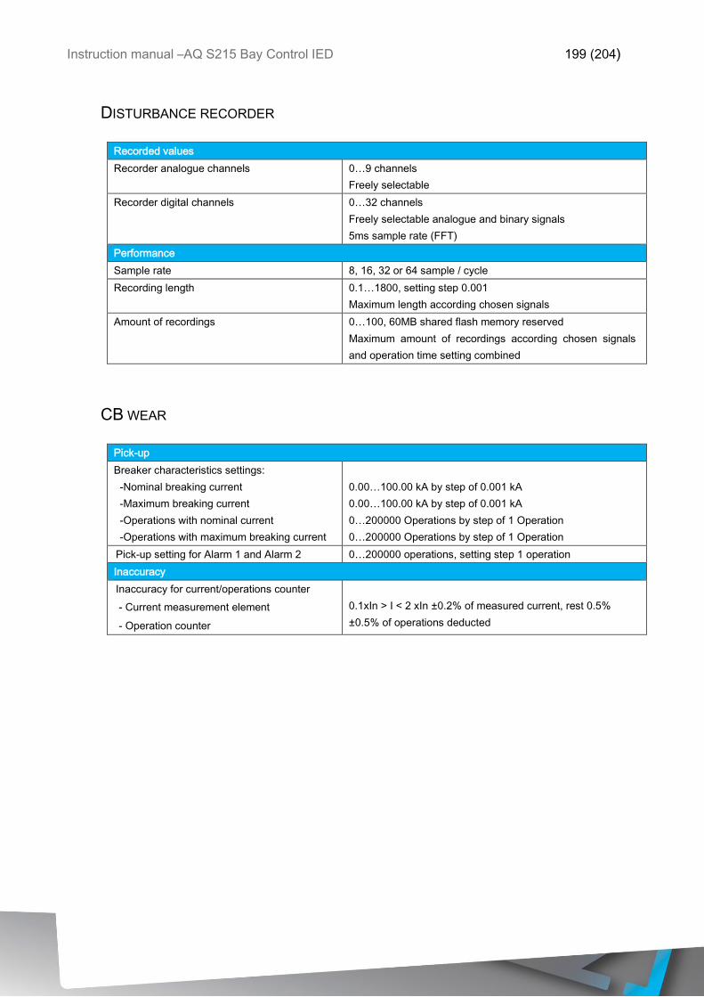
Instruction manual –AQ S215 Bay Control IED 199 (204)
DISTURBANCE RECORDER
Recorded values
Recorder analogue channels 0…9 channels
Freely selectable
Recorder digital channels 0…32 channels
Freely selectable analogue and binary signals
5ms sample rate (FFT)
Performance
Sample rate 8, 16, 32 or 64 sample / cycle
Recording length 0.1…1800, setting step 0.001
Maximum length according chosen signals
Amount of recordings 0…100, 60MB shared flash memory reserved
Maximum amount of recordings according chosen signals
and operation time setting combined
CB WEAR
Pick-up
Breaker characteristics settings:
-Nominal breaking current
-Maximum breaking current
-Operations with nominal current
-Operations with maximum breaking current
0.00…100.00 kA by step of 0.001 kA
0.00…100.00 kA by step of 0.001 kA
0…200000 Operations by step of 1 Operation
0…200000 Operations by step of 1 Operation
Pick-up setting for Alarm 1 and Alarm 2 0…200000 operations, setting step 1 operation
Inaccuracy
Inaccuracy for current/operations counter
- - Current measurement element
- - Operation counter
0.1xIn > I < 2 xIn ±0.2% of measured current, rest 0.5%
±0.5% of operations deducted
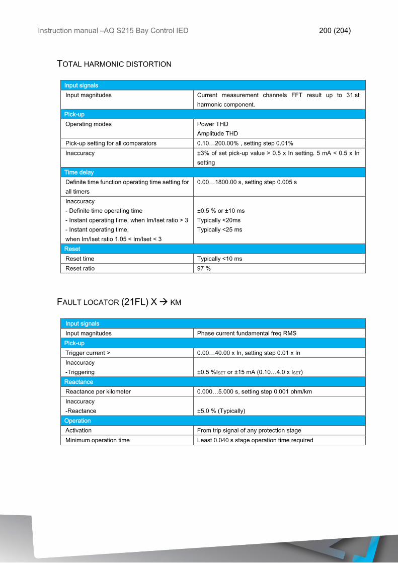
Instruction manual –AQ S215 Bay Control IED 200 (204)
TOTAL HARMONIC DISTORTION
Input signals
Input magnitudes Current measurement channels FFT result up to 31.st
harmonic component.
Pick-up
Operating modes Power THD
Amplitude THD
Pick-up setting for all comparators 0.10…200.00% , setting step 0.01%
Inaccuracy ±3% of set pick-up value > 0.5 x In setting. 5 mA < 0.5 x In
setting
Time delay
Definite time function operating time setting for
all timers
0.00…1800.00 s, setting step 0.005 s
Inaccuracy
- Definite time operating time
- Instant operating time, when Im/Iset ratio > 3
- Instant operating time,
when Im/Iset ratio 1.05 < Im/Iset < 3
±0.5 % or ±10 ms
Typically <20ms
Typically <25 ms
Reset
Reset time Typically <10 ms
Reset ratio 97 %
FAULT LOCATOR (21FL) X KM
Input signals
Input magnitudes Phase current fundamental freq RMS
Pick-up
Trigger current > 0.00…40.00 x In, setting step 0.01 x In
Inaccuracy
-Triggering
±0.5 %ISET or ±15 mA (0.10…4.0 x ISET)
Reactance
Reactance per kilometer 0.000…5.000 s, setting step 0.001 ohm/km
Inaccuracy
-Reactance
±5.0 % (Typically)
Operation
Activation From trip signal of any protection stage
Minimum operation time Least 0.040 s stage operation time required

Instruction manual –AQ S215 Bay Control IED 201 (204)
8.4 TESTS AND ENVIRONMENTAL
8.4.1 ELECTRICAL ENVIRONMENT COMPATIBILITY
Table 8.4.1-10 Disturbance tests
All tests CE approved and tested according to EN 60255-26
Emissions
Conducted emissions
EN 60255-26 Ch. 5.2, CISPR 22
Radiated emissions
EN 60255-26 Ch. 5.1, CISPR 11
150kHz - 30 MHz
30 - 1 000 MHz
Immunity
Electrostatic discharge (ESD)
EN 60255-26, IEC 61000-4-2
Fast transients (EFT)
EN 60255-26, IEC 61000-4-4
Surge
EN 60255-26, IEC 61000-4-5
Radiated RF electromagnetic field
EN 60255-26, IEC 61000-4-3
Conducted RF field
EN 60255-26, IEC 61000-4-6
Air discharge 15 kV
Contact discharge 8 kV
Power supply input 4kV, 5/50ns, 5kHz
Other inputs and outputs 4kV, 5/50ns, 5kHz
Between wires 2 kV / 1.2/50µs
Between wire and earth 4 kV / 1.2/50µs
f = 80….1000 MHz 10V /m
f = 150 kHz….80 MHz 10V
Table 8.4.1-11 Voltage tests
Dielectric voltage test
EN 60255-27, IEC 60255-5, EN 60255-1
2 kV, 50Hz, 1min
Impulse voltage test
EN 60255-27, IEC 60255-5
5 kV, 1.2/50us, 0.5J
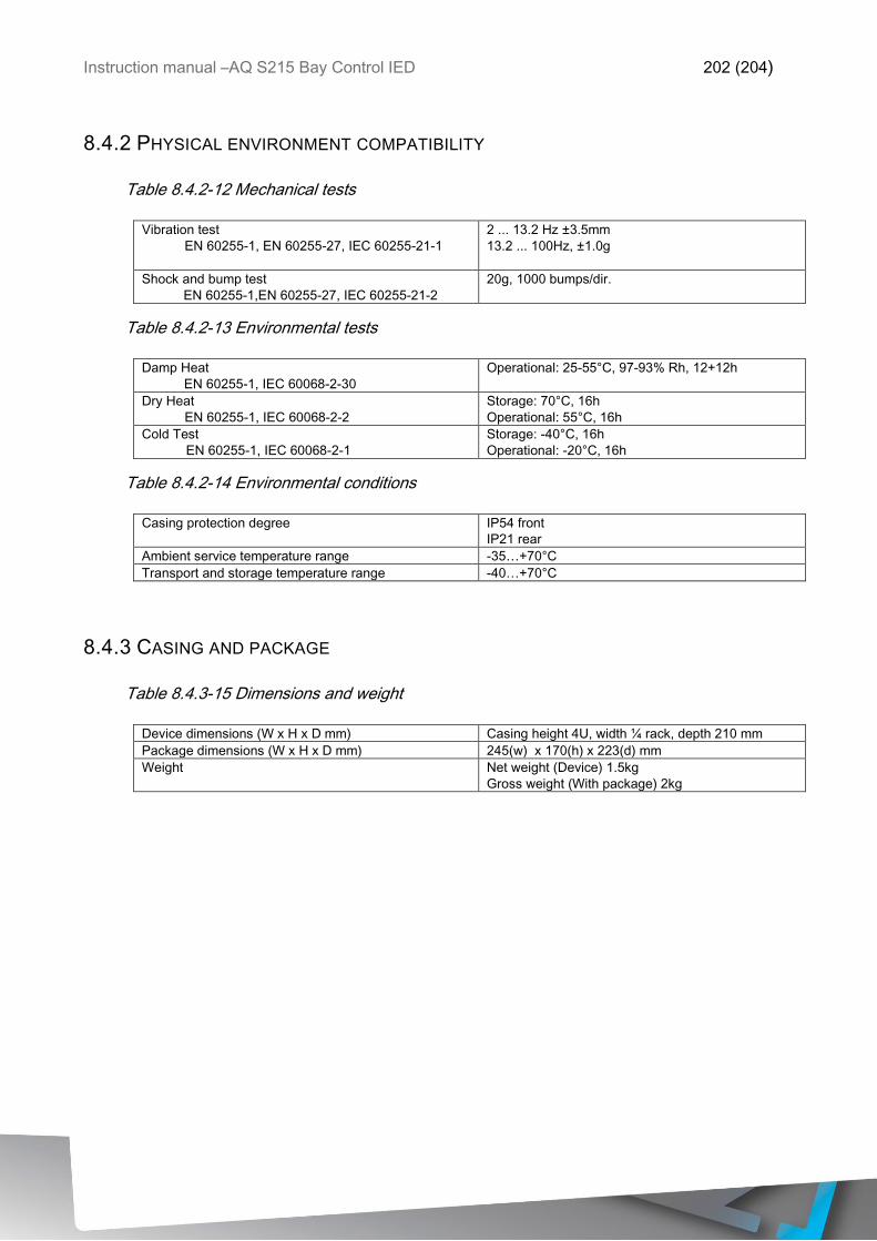
Instruction manual –AQ S215 Bay Control IED 202 (204)
8.4.2 PHYSICAL ENVIRONMENT COMPATIBILITY
Table 8.4.2-12 Mechanical tests
Vibration test
EN 60255-1, EN 60255-27, IEC 60255-21-1
2 ... 13.2 Hz ±3.5mm
13.2 ... 100Hz, ±1.0g
Shock and bump test
EN 60255-1,EN 60255-27, IEC 60255-21-2
20g, 1000 bumps/dir.
Table 8.4.2-13 Environmental tests
Damp Heat
EN 60255-1, IEC 60068-2-30
Operational: 25-55°C, 97-93% Rh, 12+12h
Dry Heat
EN 60255-1, IEC 60068-2-2
Storage: 70°C, 16h
Operational: 55°C, 16h
Cold Test
EN 60255-1, IEC 60068-2-1
Storage: -40°C, 16h
Operational: -20°C, 16h
Table 8.4.2-14 Environmental conditions
Casing protection degree IP54 front
IP21 rear
Ambient service temperature range -35…+70°C
Transport and storage temperature range -40…+70°C
8.4.3 CASING AND PACKAGE
Table 8.4.3-15 Dimensions and weight
Device dimensions (W x H x D mm) Casing height 4U, width ¼ rack, depth 210 mm
Package dimensions (W x H x D mm) 245(w) x 170(h) x 223(d) mm
Weight Net weight (Device) 1.5kg
Gross weight (With package) 2kg
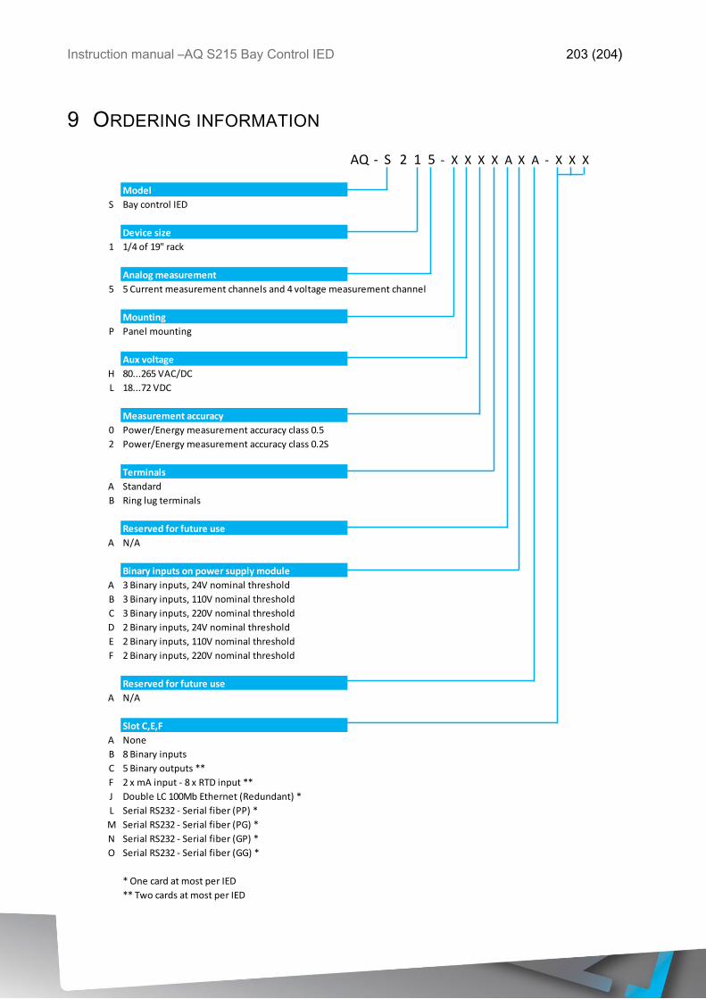
Instruction manual –AQ S215 Bay Control IED 203 (204)
9 ORDERING INFORMATION
AQ - S 2 1 5 - X X X X A X A - X X X
Model
S Bay control IED
Device size
1 1/4 of 19" rack
Analog measurement
5 5 Current measurement channels and 4 voltage measurement channel
Mounting
P Panel mounting
Aux voltage
H 80...265 VAC/DC
L 18...72 VDC
Measurement accuracy
0 Power/Energy measurement accuracy class 0.5
2 Power/Energy measurement accuracy class 0.2S
Terminals
A Standard
B Ring lug terminals
Reserved for future use
A N/A
Binary inputs on power supply module
A 3 Binary inputs, 24V nominal threshold
B 3 Binary inputs, 110V nominal threshold
C 3 Binary inputs, 220V nominal threshold
D 2 Binary inputs, 24V nominal threshold
E 2 Binary inputs, 110V nominal threshold
F 2 Binary inputs, 220V nominal threshold
Reserved for future use
A N/A
Slot C,E,F
A None
B 8 Binary inputs
C 5 Binary outputs **
F 2 x mA input - 8 x RTD input **
J Double LC 100Mb Ethernet (Redundant) *
L Serial RS232 - Serial fiber (PP) *
M Serial RS232 - Serial fiber (PG) *
N Serial RS232 - Serial fiber (GP) *
O Serial RS232 - Serial fiber (GG) *
* One card at most per IED
** Two cards at most per IED

Instruction manual –AQ S215 Bay Control IED 204 (204)
10 REFERENCE INFORMATION
Manufacturer information:
Arcteq Relays Ltd. Finland
Visiting and postal address:
Wolffintie 36 F 12
65200 Vaasa, Finland
Contacts:
Phone, general and commercial issues (office hours GMT +2): +358 10 3221 370
Fax: +358 10 3221 389
url: www.arcteq.fi
email sales: [email protected]
email technical support: [email protected]
Arcteq support line +358 10 3221 388 EET 8:00 – 16:00.