Embed Size (px)
Citation preview
SD Logo is a trademark of SD-3C, LLC
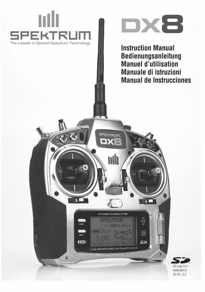
Instruction ManualBedienungsanleitungManuel d’utilisationManuale di istruzioniManual de Instrucciones
The Leader in Spread Spectrum Technology

SD Logo is a trademark of SD-3C, LLC
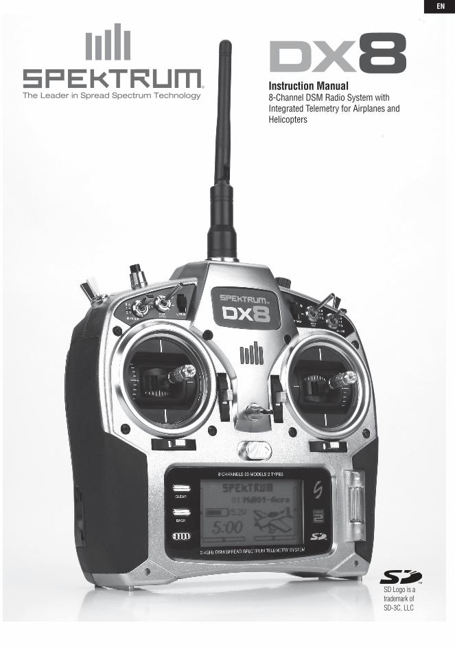
Instruction Manual8-Channel DSM Radio System with Integrated Telemetry for Airplanes and Helicopters
The Leader in Spread Spectrum Technology
EN
4 SPEKTRUM DX8 • RADIO INSTRUCTION MANUAL
NOTICEAll instructions, warranties and other collateral documents are subject to change at the sole discretion of Horizon Hobby, Inc.
For up to date product literature, visit http://www.horizonhobby.com/ProdInfo/Files/SPM8800-manual.pdf.
Meaning of Special Language:The following terms are used throughout the product literature to indicate various levels of potential harm when operating this product:
NOTICE: Procedures, which if not properly followed, create a possibility of physical property damage AND a little or no possibility of injury
CAUTION: Procedures, which if not properly followed, create the probability of physical property damage AND a possibility of serious injury.
WARNING: Procedures, which if not properly followed, create the probability of property damage, collateral damage, and serious injury OR create a high probability of superficial injury.
WARNING: Read the ENTIRE instruction manual to become familiar with the features of the product before operating. Failure to operate the product correctly can result in damage to the product, personal
property and cause serious injury.
This is a sophisticated hobby product and NOT a toy. It must be operated with caution and common sense and requires some basic mechanical ability. Failure to operate this Product in a safe and responsible manner could result in injury or damage to the product or other property. This product is not intended for use by children without direct adult supervision. Do not attempt disassembly, use with incompatible components or augment product in any way without the approval of Horizon Hobby, Inc. This manual contains instructions for safety, operation and maintenance. It is essential to read and follow all the instructions and warnings in the manual, prior to assembly, setup or use, in order to operate correctly and avoid damage or serious injury.
WARNING AGAINST COUNTERFEIT PRODUCTS Thank You for purchasing a genuine Spektrum Product. Always purchase products from a Horizon Hobby, Inc. authorized
dealer to ensure authentic high-quality Spektrum product. Horizon Hobby, Inc. disclaims all support and warranty with regards, but not limited to, compatibility and performance of counterfeit products or products claiming compatibility with DSM2 or Spektrum.
WARRANTY REGISTRATIONVisit www.spektrumrc.com/registration today to register your product.
EN
5SPEKTRUM DX8 • RADIO INSTRUCTION MANUAL
Spektrum’s DX8 with Integrated Telemetry ......................................................6Included Items ..................................................................................................6System Features ...............................................................................................6Charging Your Transmitter ................................................................................7NiMH/LiPo Battery Support ..............................................................................7Battery and Charging Precautions and Warnings .............................................7Transmitter Identification Mode 2 .....................................................................8Transmitter Identification Mode 1 .....................................................................9Key Input and Display Functions ....................................................................10Digital Trims ...................................................................................................10Inactivity Warnings .........................................................................................10No RF Output Warning ...................................................................................10Battery Alarm and Display ..............................................................................10Programmable Alarms ....................................................................................10AR8000 Receiver ............................................................................................10Receiver Installation........................................................................................11Binding ...........................................................................................................11Failsafe ...........................................................................................................12SmartSafe .......................................................................................................12Hold Last Command Failsafe .........................................................................12Preset Failsafe ................................................................................................12Range Testing .................................................................................................13System Setup ...........................................................................................13Model Select ...................................................................................................14Model Type .....................................................................................................14Model Name ...................................................................................................15Wing Type .......................................................................................................15Switch Select (Air) ..........................................................................................15Swash Type .....................................................................................................15Switch Select (Heli) ........................................................................................16F-Mode Setup.................................................................................................16Trim Step ........................................................................................................16Model Reset ....................................................................................................17Model Copy ....................................................................................................17Warnings ........................................................................................................18Telemetry ........................................................................................................18Frame Rate ......................................................................................................20Trainer .............................................................................................................20System Settings ..............................................................................................20Transfer SD Card ............................................................................................21Function Mode ........................................................................................22Servo Setup ....................................................................................................22D/R and Exponential .......................................................................................23Differential ......................................................................................................24Throttle Cut .....................................................................................................25Throttle Curve (Air) .........................................................................................25Throttle Curve (Heli) .......................................................................................26Flap System ....................................................................................................26Swashplate .....................................................................................................27Governor .........................................................................................................28Pitch Curve .....................................................................................................28Mixing (Air) ....................................................................................................29Aileron to Rudder Mix ....................................................................................29Programmable Mixes (Air) .............................................................................29Tail Curve for Non-Heading Hold Gyro Use Only ...........................................30Mixing (Heli) ..................................................................................................31Gyro ................................................................................................................33Timer ..............................................................................................................33Monitor ...........................................................................................................35
Troubleshooting Guide ...................................................................................35General Information ........................................................................................36 Servo Precautions General Notes Safety Do’s and Don’ts for Pilots Federal Aviation Administration.................................................................36 Purpose Background Operating Standards Information Provided by Daily Flight ChecksWarranty and Repair Policy ............................................................................37 Warranty Period 1-Year Limited Warranty Damage Limits Safety Precautions Warranty Services Questions, Assistance, and Repairs Inspection or Repairs Warranty Inspection and Repairs ...............................................................38 Non-Warranty RepairsFCC Information .............................................................................................38Antenna Separation Distance ..........................................................................38Compliance Information for the European Union ...........................................39Declaration of Conformity...............................................................................39Instructions for the Disposal of WEEE ............................................................39 Appendix ......................................................................................................39 Mode Changes ..........................................................................................39 Mechanical Conversion .............................................................................39 Programming Conversion .........................................................................40 Adjustable Stick Tension ...........................................................................41 Advanced Range Testing ............................................................................41 Using a Flight Log—Optional ...................................................................42
TAbLE OF CONTENTS
EN
6 SPEKTRUM DX8 • RADIO INSTRUCTION MANUAL
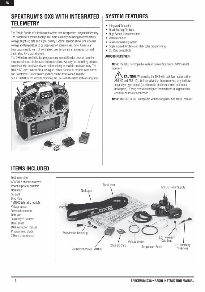
SPEKTRUM’S DX8 WITh INTEGRATED TELEMETRY The DX8 is Spektrum’s first aircraft system that incorporates integrated telemetry. The transmitter’s screen displays real-time telemetry including receiver battery voltage, flight log data and signal quality. External sensors allow rpm, external voltage and temperature to be displayed on screen in real time. Alarms can be programmed to warn of low battery, over temperature, exceeded rpm and diminished RF signal strength.The DX8 offers sophisticated programming to meet the demands of even the most experienced airplane and helicopter pilots. An easy-to-use rolling selector combined with intuitive software makes setting up models quick and easy. The DX8 is SD-card compatible allowing an infinite number of models to be stored and transferred. Plus firmware updates can be downloaded from the SPEKTRUMRC.com website providing the user with the latest software upgrades.
SYSTEM FEATURES
Integrated Telemetry•Quad Bearing Gimbals•High Speed 11ms frame rate•2048 resolution•Telemetry warning system•Sophisticated Airplane and Helicopter programming•SD Card compatible•
AR8000 RECEIvER
Note: The DX8 is compatible with all current Spektrum DSM2 aircraft receivers.
CAUTION: When using the DX8 with parkflyer receivers (the AR6100 and AR6110), it’s imperative that these receivers only be flown in parkflyer-type aircraft (small electric airplanes or mini and micro helicopters). Flying receivers designed for parkflyers in larger aircraft could cause loss of connection.
Note: The DX8 is NOT compatible with the original DSM AR600 receiver.
ITEMS INCLUDED
DX8 transmitterAR8000 8-channel receiverPower supply w/ adaptorsNeckstrapSD cardBind PlugTM1000 telemetry moduleVoltage sensorTemperature sensorData leadTelemetry Y-HarnessDecal sheetDX8 instruction manualProgramming Guide2.0mm L hex wrench
Telemetry module (TM1000)
Voltage Sensor
Temperature Sensor
2.5” TelemetryData Lead
2.5” Telemetry Y-harness
16MB SD Card
Male/female bind plug
12V DC Power SupplyNeckstrap
Decal sheet
EN
7SPEKTRUM DX8 • RADIO INSTRUCTION MANUAL
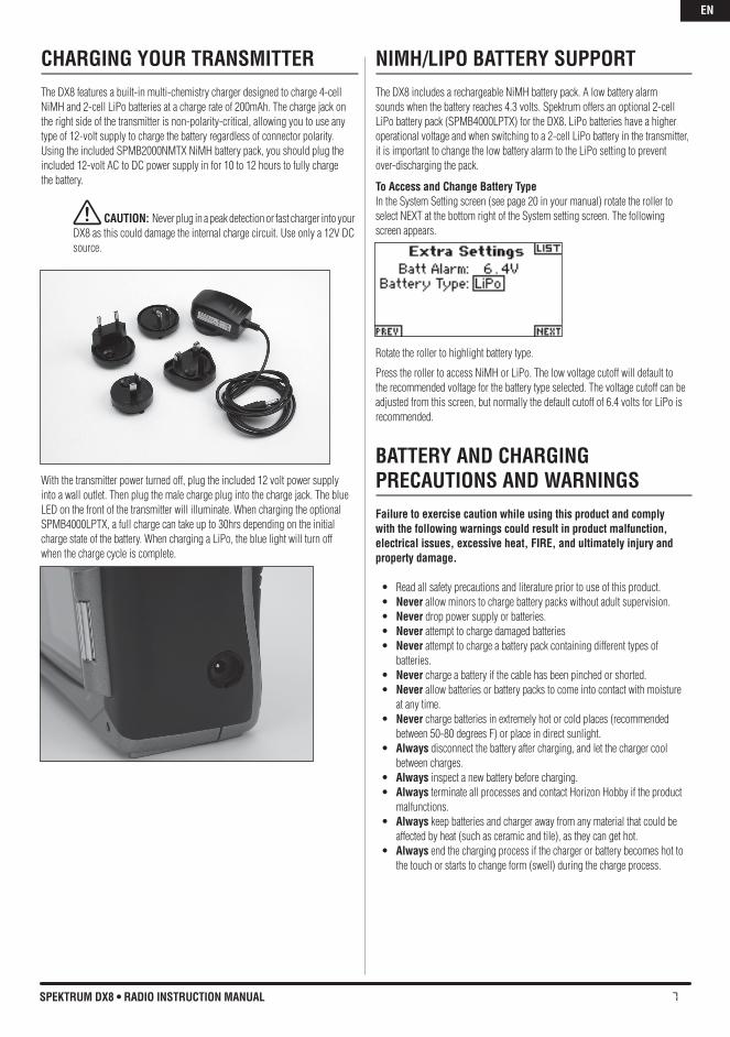
ChARGING YOUR TRANSMITTERThe DX8 features a built-in multi-chemistry charger designed to charge 4-cell NiMH and 2-cell LiPo batteries at a charge rate of 200mAh. The charge jack on the right side of the transmitter is non-polarity-critical, allowing you to use any type of 12-volt supply to charge the battery regardless of connector polarity. Using the included SPMB2000NMTX NiMH battery pack, you should plug the included 12-volt AC to DC power supply in for 10 to 12 hours to fully charge the battery.
CAUTION: Never plug in a peak detection or fast charger into your DX8 as this could damage the internal charge circuit. Use only a 12V DC source.
With the transmitter power turned off, plug the included 12 volt power supply into a wall outlet. Then plug the male charge plug into the charge jack. The blue LED on the front of the transmitter will illuminate. When charging the optional SPMB4000LPTX, a full charge can take up to 30hrs depending on the initial charge state of the battery. When charging a LiPo, the blue light will turn off when the charge cycle is complete.
NIMh/LIPO bATTERY SUPPORTThe DX8 includes a rechargeable NiMH battery pack. A low battery alarm sounds when the battery reaches 4.3 volts. Spektrum offers an optional 2-cell LiPo battery pack (SPMB4000LPTX) for the DX8. LiPo batteries have a higher operational voltage and when switching to a 2-cell LiPo battery in the transmitter, it is important to change the low battery alarm to the LiPo setting to prevent over-discharging the pack.
To Access and Change battery TypeIn the System Setting screen (see page 20 in your manual) rotate the roller to select NEXT at the bottom right of the System setting screen. The following screen appears.
Rotate the roller to highlight battery type.
Press the roller to access NiMH or LiPo. The low voltage cutoff will default to the recommended voltage for the battery type selected. The voltage cutoff can be adjusted from this screen, but normally the default cutoff of 6.4 volts for LiPo is recommended.
bATTERY AND ChARGING PRECAUTIONS AND WARNINGSFailure to exercise caution while using this product and comply with the following warnings could result in product malfunction, electrical issues, excessive heat, FIRE, and ultimately injury and property damage.
• Readallsafetyprecautionsandliteraturepriortouseofthisproduct.• Never allow minors to charge battery packs without adult supervision. • Never drop power supply or batteries.• Never attempt to charge damaged batteries• Never attempt to charge a battery pack containing different types of
batteries.• Never charge a battery if the cable has been pinched or shorted. • Never allow batteries or battery packs to come into contact with moisture
at any time.• Never charge batteries in extremely hot or cold places (recommended
between 50-80 degrees F) or place in direct sunlight. • Always disconnect the battery after charging, and let the charger cool
between charges.• Always inspect a new battery before charging.• Always terminate all processes and contact Horizon Hobby if the product
malfunctions.• Always keep batteries and charger away from any material that could be
affected by heat (such as ceramic and tile), as they can get hot. • Always end the charging process if the charger or battery becomes hot to
the touch or starts to change form (swell) during the charge process.
EN
8 SPEKTRUM DX8 • RADIO INSTRUCTION MANUAL
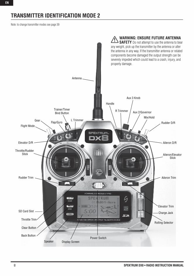
TRANSMITTER IDENTIFICATION MODE 2Note: to change transmitter modes see page 39
Antenna
Rolling Selector
Aileron/ElevatorStick
Elevator Trim
Aileron Trim
Power Switch
SD Card Slot
Throttle Trim
Throttle/Rudder
Stick
Handle
Rudder Trim
Elevator D/R
Clear Button
Back Button
Display ScreenSpeaker
Mix/Hold
Aileron D/R
Rudder D/R
Aux 2/Governor
Charge Jack
R Trimmer
Aux 3 Knob
Trainer/TimerBind Button
Flap/GyroGear
Flight Mode
L Trimmer
WARNING: ENSURE FUTURE ANTENNA SAFETY Do not attempt to use the antenna to bear
any weight, pick up the transmitter by the antenna or alter the antenna in any way. If the transmitter antenna or related components become damaged the output strength can be severely impeded which could lead to a crash, injury, and property damage.
EN
9SPEKTRUM DX8 • RADIO INSTRUCTION MANUAL
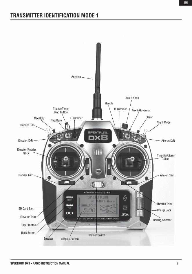
TRANSMITTER IDENTIFICATION MODE 1
Antenna
Rolling Selector
Throttle/AileronStick
Throttle Trim
Aileron Trim
Power Switch
SD Card Slot
Elevator Trim
Elevator/RudderStick
Handle
Rudder Trim
Elevator D/R
Clear Button
Back Button
Display ScreenSpeaker
Mix/Hold
Aileron D/R
Flight Mode
Aux 2/Governor
Charge Jack
R Trimmer
Aux 3 Knob
Trainer/TimerBind Button
Flap/GyroGear
Rudder D/R
L Trimmer
EN
10 SPEKTRUM DX8 • RADIO INSTRUCTION MANUAL
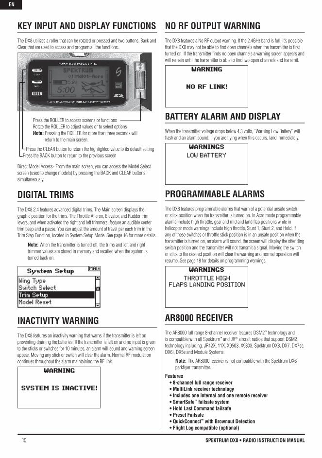
KEY INPUT AND DISPLAY FUNCTIONSThe DX8 utilizes a roller that can be rotated or pressed and two buttons, Back and Clear that are used to access and program all the functions.
Direct Model Access- From the main screen, you can access the Model Select screen (used to change models) by pressing the BACK and CLEAR buttons simultaneously.
DIGITAL TRIMSThe DX8 2.4 features advanced digital trims. The Main screen displays the graphic position for the trims. The Throttle Aileron, Elevator, and Rudder trim levers, and when activated the right and left trimmers, feature an audible center trim beep and a pause. You can adjust the amount of travel per each trim in the Trim Step Function, located in System Setup Mode. See page 16 for more details.
Note: When the transmitter is turned off, the trims and left and right trimmer values are stored in memory and recalled when the system is turned back on.
INACTIvITY WARNINGThe DX8 features an inactivity warning that warns if the transmitter is left on preventing draining the batteries. If the transmitter is left on and no input is given to the sticks or switches for 10 minutes, an alarm will sound and warning screen appear. Moving any stick or switch will clear the alarm. Normal RF modulation continues throughout the alarm maintaining the RF link.
NO RF OUTPUT WARNINGThe DX8 features a No RF output warning. If the 2.4GHz band is full, it’s possible that the DX8 may not be able to find open channels when the transmitter is first turned on. If the transmitter finds no open channels a warning screen appears and will remain until the transmitter is able to find two open channels and transmit.
bATTERY ALARM AND DISPLAYWhen the transmitter voltage drops below 4.3 volts, “Warning Low Battery” will flash and an alarm sound. If you are flying when this occurs, land immediately.
PROGRAMMAbLE ALARMSThe DX8 features programmable alarms that warn of a potential unsafe switch or stick position when the transmitter is turned on. In Acro mode programmable alarms include high throttle, gear and mid and land flap positions while in helicopter mode warnings include high throttle, Stunt 1, Stunt 2, and Hold. If any of these switches or throttle stick position is in an unsafe position when the transmitter is turned on, an alarm will sound, the screen will display the offending switch position and the transmitter will not transmit a signal. Moving the switch or stick to the desired position will clear the warning and normal operation will resume. See page 18 for details on programming warnings.
AR8000 RECEIvERThe AR8000 full range 8-channel receiver features DSM2™ technology and is compatible with all Spektrum™ and JR® aircraft radios that support DSM2 technology including: JR12X, 11X, X9503, X9303, Spektrum DX8, DX7, DX7se, DX6i, DX5e and Module Systems.
Note: The AR8000 receiver is not compatible with the Spektrum DX6 parkflyer transmitter.
Features • 8-channel full range receiver • MultiLink receiver technology • Includes one internal and one remote receiver • SmartSafe™ failsafe system • hold Last Command failsafe • Preset Failsafe • QuickConnect™ with brownout Detection • Flight Log compatible (optional)
Press the ROLLER to access screens or functions Rotate the ROLLER to adjust values or to select options Note: Pressing the ROLLER for more than three seconds will return to the main screen.
Press the CLEAR button to return the highlighted value to its default setting Press the BACK button to return to the previous screen
EN
11SPEKTRUM DX8 • RADIO INSTRUCTION MANUAL
• 2048 Resolution • high-speed 11ms operation when used with capable transmitters • hold indicator (Red LED indicates number of holds incurred
during flight).
ApplicationsFull range up to 8-channel aircraft including: •Alltypesandsizesofglow,gasandelectricpoweredairplanes •Alltypesandsizesofno-poweredgliders •Alltypesandsizesofglow,gasandelectricpoweredhelicopters
Note: Not for use in airplanes that have full carbon fuselages. Not for use in airplanes that have significant carbon or conductive structures. It is recommended to use one of the carbon fuselage receivers. (SPMAR9300, SPMAR6255).
Specifications: Type: DSM2 full range receiver Channels: 8 Modulation: DSM2 Main Receiver Dimensions: 1.27 x 1.35 x 0.45 in (32.3 x 34.3 x 11.4mm) Remote Receiver Dimensions: 0.80 x 1.10 x 0.27 in (20.3 x 28.0 x 6.9mm) Main Receiver Weight: .33 oz (9.4 g) Remote Receiver Weight: .2 oz (3 g) Weight with Remote Receiver: .49 oz (13.9 g) voltage Range: 3.5 to 9.6v Resolution: 2048 Frame Rate: 11ms when paired with the DX7se or DX8 Compatibility: All DSM2 aircraft transmitters and module systems
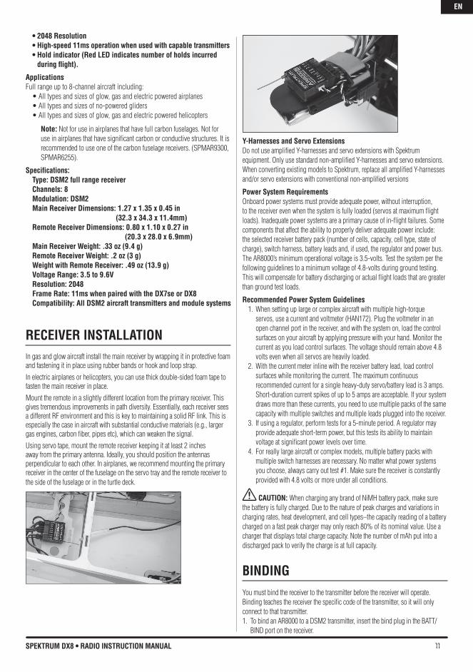
RECEIvER INSTALLATIONIn gas and glow aircraft install the main receiver by wrapping it in protective foam and fastening it in place using rubber bands or hook and loop strap. In electric airplanes or helicopters, you can use thick double-sided foam tape to fasten the main receiver in place.Mount the remote in a slightly different location from the primary receiver. This gives tremendous improvements in path diversity. Essentially, each receiver sees a different RF environment and this is key to maintaining a solid RF link. This is especially the case in aircraft with substantial conductive materials (e.g., larger gas engines, carbon fiber, pipes etc), which can weaken the signal.Using servo tape, mount the remote receiver keeping it at least 2 inches away from the primary antenna. Ideally, you should position the antennas perpendicular to each other. In airplanes, we recommend mounting the primary receiver in the center of the fuselage on the servo tray and the remote receiver to the side of the fuselage or in the turtle deck.
Y-harnesses and Servo ExtensionsDo not use amplified Y-harnesses and servo extensions with Spektrum equipment. Only use standard non-amplified Y-harnesses and servo extensions. When converting existing models to Spektrum, replace all amplified Y-harnesses and/or servo extensions with conventional non-amplified versions
Power System RequirementsOnboard power systems must provide adequate power, without interruption, to the receiver even when the system is fully loaded (servos at maximum flight loads). Inadequate power systems are a primary cause of in-flight failures. Some components that affect the ability to properly deliver adequate power include: the selected receiver battery pack (number of cells, capacity, cell type, state of charge), switch harness, battery leads and, if used, the regulator and power bus. The AR8000’s minimum operational voltage is 3.5-volts. Test the system per the following guidelines to a minimum voltage of 4.8-volts during ground testing. This will compensate for battery discharging or actual flight loads that are greater than ground test loads.
Recommended Power System Guidelines1. When setting up large or complex aircraft with multiple high-torque
servos, use a current and voltmeter (HAN172). Plug the voltmeter in an open channel port in the receiver, and with the system on, load the control surfaces on your aircraft by applying pressure with your hand. Monitor the current as you load control surfaces. The voltage should remain above 4.8 volts even when all servos are heavily loaded.
2. With the current meter inline with the receiver battery lead, load control surfaces while monitoring the current. The maximum continuous recommended current for a single heavy-duty servo/battery lead is 3 amps. Short-duration current spikes of up to 5 amps are acceptable. If your system draws more than these currents, you need to use multiple packs of the same capacity with multiple switches and multiple leads plugged into the receiver.
3. If using a regulator, perform tests for a 5-minute period. A regulator may provide adequate short-term power, but this tests its ability to maintain voltage at significant power levels over time.
4. For really large aircraft or complex models, multiple battery packs with multiple switch harnesses are necessary. No matter what power systems you choose, always carry out test #1. Make sure the receiver is constantly provided with 4.8 volts or more under all conditions.
CAUTION: When charging any brand of NiMH battery pack, make sure the battery is fully charged. Due to the nature of peak charges and variations in charging rates, heat development, and cell types–the capacity reading of a battery charged on a fast peak charger may only reach 80% of its nominal value. Use a charger that displays total charge capacity. Note the number of mAh put into a discharged pack to verify the charge is at full capacity.
bINDINGYou must bind the receiver to the transmitter before the receiver will operate. Binding teaches the receiver the specific code of the transmitter, so it will only connect to that transmitter. 1. To bind an AR8000 to a DSM2 transmitter, insert the bind plug in the BATT/
BIND port on the receiver.
EN
12 SPEKTRUM DX8 • RADIO INSTRUCTION MANUAL
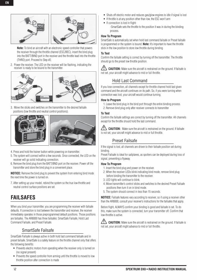
Note: To bind an aircraft with an electronic speed controller that powers the receiver through the throttle channel (ESC/BEC), insert the bind plug into the BATT/BIND port in the receiver and the throttle lead into the throttle (THRO) port. Proceed to Step #2.
2. Power the receiver. The LED on the receiver will be flashing, indicating the receiver is ready to be bound to the transmitter.
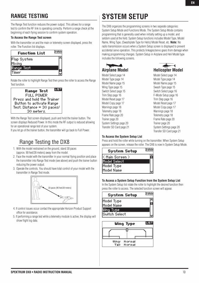
3. Move the sticks and switches on the transmitter to the desired failsafe positions (low throttle and neutral control positions).
4. Press and hold the trainer button while powering on transmitter.5. The system will connect within a few seconds. Once connected, the LED on the
receiver will go solid indicating connection.6. Remove the bind plug from the BATT/BND port on the receiver. Power off the
transmitter and store the bind plug in a convenient place.
NOTICE: Remove the bind plug to prevent the system from entering bind mode the next time the power is turned on.
7. After setting up your model, rebind the system so the true low throttle and neutral control surface positions are set.
FAILSAFESWhen you bind your transmitter, you are programming the receiver with failsafe defaults. If connection is lost between the transmitter and receiver, the receiver immediately operates in those preprogrammed default positions. Those positions are failsafes. The AR8000 has three failsafes: SmartSafe Failsafe, Hold Last Command Failsafe, and Preset Failsafe.
SmartSafe FailsafeSmartSafe Failsafe is always active in both hold last command failsafe and in preset failsafe. SmartSafe is a safety feature on the throttle channel only that offers the following benefits:• Preventselectricmotorsfromoperatingwhenthereceiveronlyisturnedon
(no signal present)• Preventsthespeedcontrollerfromarminguntilthethrottleismovedtolow
throttle position after connection is made
• Shutsoffelectricmotorandreducesgas/glowenginestoidleifsignalislost• Ifthrottleisatanypositionotherthanlow,theESCwon’tarm• Ifconnectionislostinflight:
-SmartSafe sets the throttle to the position it was in during the binding process.
how To ProgramSmartSafe is automatically set when hold last command failsafe or Preset failsafe is programmed or the system is bound. Note: It’s important to have the throttle stick in the low position to store low throttle during binding
To TestConfirm the failsafe setting is correct by turning off the transmitter. The throttle should go to the preset low throttle position.
CAUTION: Make sure the aircraft is restrained on the ground. If failsafe is not set, your aircraft might advance to mid or full throttle.
Hold Last CommandIf you lose connection, all channels except for throttle channel hold last given command and the aircraft continues on its path. So, if you were turning when connection was lost, your aircraft would continue turning.
how to Program1. Leave the bind plug in the bind port through the entire binding process.2. Remove bind plug only after receiver connects to transmitter
To TestConfirm the failsafe settings are correct by turning off the transmitter. All channels except for the throttle should hold the last command.
CAUTION: Make sure the aircraft is restrained on the ground. If failsafe is not set, your aircraft might advance to mid or full throttle.
Preset FailsafeIf the signal is lost, all channels are driven to their failsafe position set during binding.Preset Failsafe is ideal for sailplanes, as spoliers can be deployed during loss of signal, preventing a flyaway.
how To Program1. Insert the bind plug and power on the receiver.2. When the receiver LEDs blink indicating bind mode, remove bind plug
before binding the transmitter to the receiver.3. LED lights will continue to blink.4. Move transmitter’s control sticks and switches to the desired Preset Failsafe
positions then turn it on in bind mode.5. The system should connect in less than 15 seconds.
NOTICE: Failsafe features vary according to receiver, so if using a receiver other than the AR8000, consult your receiver’s instructions for the failsafes that apply.
Before flight, ALWAYS confirm your binding is good and failsafe is set. To do this, make sure the system is connected, turn your transmitter off. Confirm that low-throttle is active.
CAUTION: Make sure the aircraft is restrained on the ground. If failsafe is not set, your aircraft might advance to mid or full throttle.
EN
13SPEKTRUM DX8 • RADIO INSTRUCTION MANUAL
RANGE TESTINGThe Range Test function reduces the power output. This allows for a range test to confirm the RF link is operating correctly. Perform a range check at the beginning of each flying session to confirm system operation.
To Access the Range Test screen
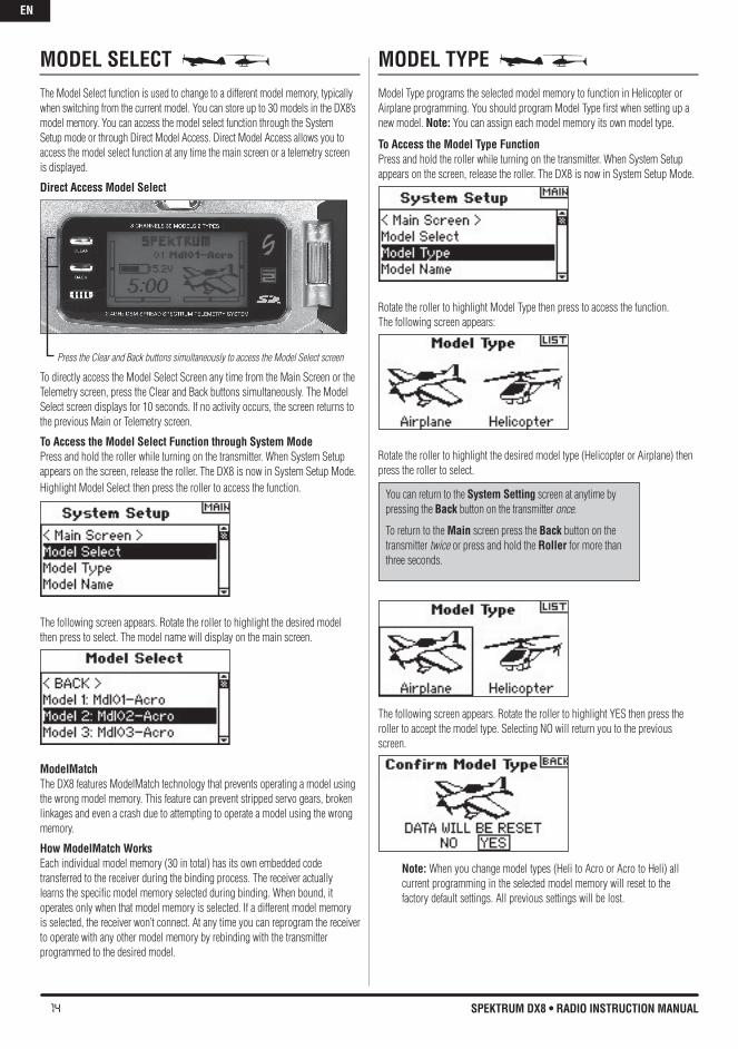
With the transmitter on and the main or telemetry screen displayed, press the roller. The Function list displays.
Rotate the roller to highlight Range Test then press the roller to access the Range Test function.
With the Range Test screen displayed, push and hold the trainer button. The screen displays Reduced Power. In this mode the RF output is reduced allowing for an operational range test of your system.If you let go of the trainer button, the transmitter will go back to Full Power.
Range Testing the DX81. With the model restrained on the ground, stand 30 paces
(approx. 90 feet/28 meters) away from the model. 2. Face the model with the transmitter in your normal flying position and place
the transmitter into Range Test mode (see above) and push the trainer button reducing the power output.
3. Operate the controls. You should have total control of your model with the transmitter in Range Test mode.
4. If control issues occur contact the appropriate Horizon Product Support office for assistance.
5. If performing a range test while a telemetry module is active, the display will show flight log data.
SYSTEM SETUPThe DX8 organizes the programming screens in two separate categories: System Setup Mode and Functions Mode. The System Setup Mode contains programming that is generally used when initially setting up a model, and seldom used at the field. System Setup functions includes Model Type, Model Name, Wing Type, (Swashplate Type for Helis) Model Reset, etc. Note: No radio transmission occurs when a System Setup screen is displayed to prevent accidental servo operation. This protects linkages/servo gears from damage when making programming changes. System Setup in Airplane and Heli Model type includes the following screens.
Airplane Model helicopter Model Model Select page 14 Model Select page 14 Model Type page 14 Model Type page 14 Model Name page 15 Model Name page 15 Wing Type page 15 Swash Type page 15 Switch Select page 15 Switch Select page 16 Trim Step page 16 F-Mode Setup page 16 Model Reset page 17 Trim Step page 16 Model Copy page 17 Model Reset page 17 Warnings page 18 Model Copy page 17 Telemetry page 18 Warnings page 18 Frame Rate page 20 Telemetry page 18 Trainer page 20 Frame Rate page 20 System Settings page 20 Trainer page 20 Transfer SD Card page 21 System Settings page 20 Transfer SD Card page 21
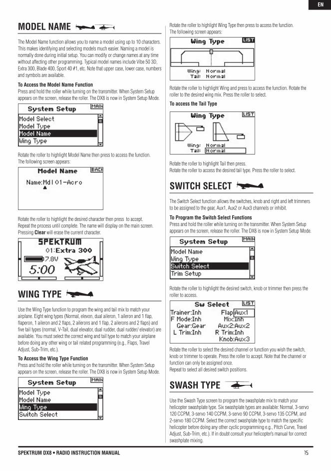
To Access the System Setup ListPress and hold the roller while turning on the transmitter. When System Setup appears on the screen, release the roller. The DX8 is now in System Setup Mode.
To Access a System Setup Function from the System Setup ListIn the System Setup list rotate the roller to highlight the desired function then press the roller to access. The selected function screen will appear.30 paces (90 feet/28 meters)
EN
14 SPEKTRUM DX8 • RADIO INSTRUCTION MANUAL
MODEL SELECT The Model Select function is used to change to a different model memory, typically when switching from the current model. You can store up to 30 models in the DX8’s model memory. You can access the model select function through the System Setup mode or through Direct Model Access. Direct Model Access allows you to access the model select function at any time the main screen or a telemetry screen is displayed.
Direct Access Model Select
Press the Clear and Back buttons simultaneously to access the Model Select screen
To directly access the Model Select Screen any time from the Main Screen or the Telemetry screen, press the Clear and Back buttons simultaneously. The Model Select screen displays for 10 seconds. If no activity occurs, the screen returns to the previous Main or Telemetry screen.
To Access the Model Select Function through System ModePress and hold the roller while turning on the transmitter. When System Setup appears on the screen, release the roller. The DX8 is now in System Setup Mode.Highlight Model Select then press the roller to access the function.
The following screen appears. Rotate the roller to highlight the desired model then press to select. The model name will display on the main screen.
ModelMatchThe DX8 features ModelMatch technology that prevents operating a model using the wrong model memory. This feature can prevent stripped servo gears, broken linkages and even a crash due to attempting to operate a model using the wrong memory.
how ModelMatch WorksEach individual model memory (30 in total) has its own embedded code transferred to the receiver during the binding process. The receiver actually learns the specific model memory selected during binding. When bound, it operates only when that model memory is selected. If a different model memory is selected, the receiver won’t connect. At any time you can reprogram the receiver to operate with any other model memory by rebinding with the transmitter programmed to the desired model.
MODEL TYPE Model Type programs the selected model memory to function in Helicopter or Airplane programming. You should program Model Type first when setting up a new model. Note: You can assign each model memory its own model type.
To Access the Model Type FunctionPress and hold the roller while turning on the transmitter. When System Setup appears on the screen, release the roller. The DX8 is now in System Setup Mode.
Rotate the roller to highlight Model Type then press to access the function. The following screen appears:
Rotate the roller to highlight the desired model type (Helicopter or Airplane) then press the roller to select.
The following screen appears. Rotate the roller to highlight YES then press the roller to accept the model type. Selecting NO will return you to the previous screen.
Note: When you change model types (Heli to Acro or Acro to Heli) all current programming in the selected model memory will reset to the factory default settings. All previous settings will be lost.
You can return to the System Setting screen at anytime by pressing the back button on the transmitter once.
To return to the Main screen press the back button on the transmitter twice or press and hold the Roller for more than three seconds.
EN
15SPEKTRUM DX8 • RADIO INSTRUCTION MANUAL
MODEL NAME The Model Name function allows you to name a model using up to 10 characters. This makes identifying and selecting models much easier. Naming a model is normally done during initial setup. You can modify or change names at any time without affecting other programming. Typical model names include Vibe 50 3D, Extra 300, Blade 400, Sport 40 #1, etc. Note that upper case, lower case, numbers and symbols are available.
To Access the Model Name FunctionPress and hold the roller while turning on the transmitter. When System Setup appears on the screen, release the roller. The DX8 is now in System Setup Mode.
Rotate the roller to highlight Model Name then press to access the function. The following screen appears:
Rotate the roller to highlight the desired character then press to accept. Repeat the process until complete. The name will display on the main screen. Pressing Clear will erase the current character.
WING TYPE Use the Wing Type function to program the wing and tail mix to match your airplane. Eight wing types (Normal, elevon, dual aileron, 1 aileron and 1 flap, flaperon, 1 aileron and 2 flaps, 2 ailerons and 1 flap, 2 ailerons and 2 flaps) and five tail types (normal, V-Tail, dual elevator, dual rudder, dual rudder/ elevator) are available. You must select the correct wing and tail type to match your airplane before doing any other wing or tail related programming (e.g., Flaps, Travel Adjust, Sub-Trim, etc.).
To Access the Wing Type FunctionPress and hold the roller while turning on the transmitter. When System Setup appears on the screen, release the roller. The DX8 is now in System Setup Mode.
Rotate the roller to highlight Wing Type then press to access the function. The following screen appears:
Rotate the roller to highlight Wing and press to access the function. Rotate the roller to the desired wing mix. Press the roller to select.
To access the Tail Type
Rotate the roller to highlight Tail then press. Rotate the roller to access the desired tail type. Press the roller to select.
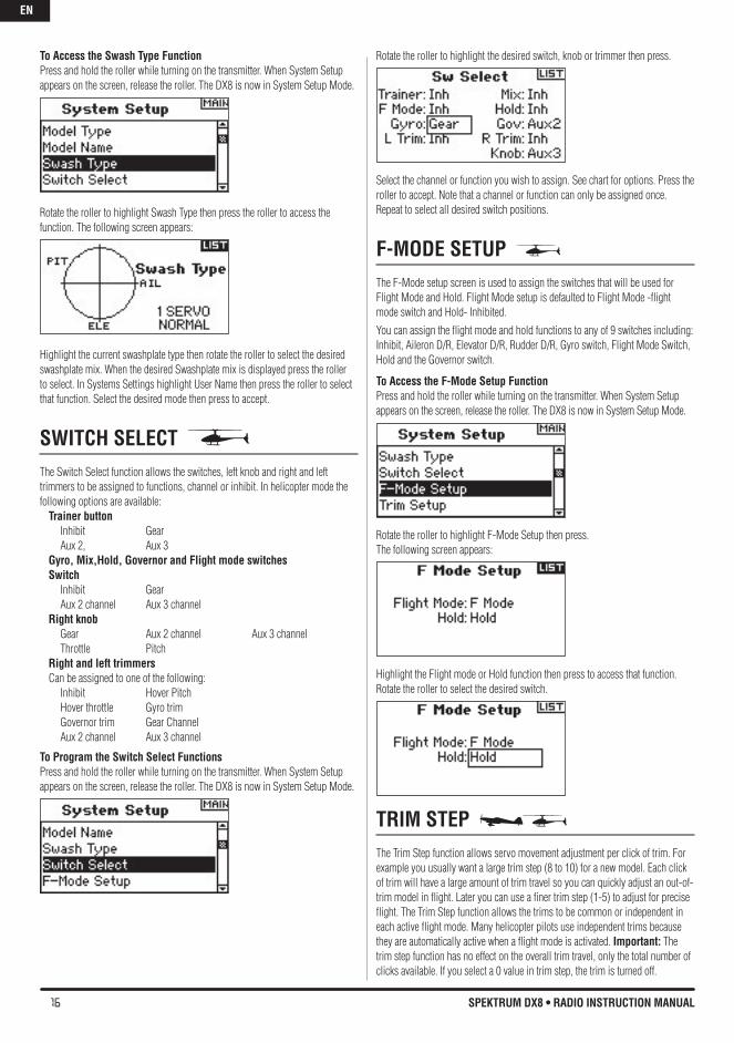
SWITCh SELECT The Switch Select function allows the switches, knob and right and left trimmers to be assigned to the gear, Aux1, Aux2 or Aux3 channels or inhibit.
To Program the Switch Select FunctionsPress and hold the roller while turning on the transmitter. When System Setup appears on the screen, release the roller. The DX8 is now in System Setup Mode.
Rotate the roller to highlight the desired switch, knob or trimmer then press the roller to access.
Rotate the roller to select the desired channel or function you wish the switch, knob or trimmer to operate. Press the roller to accept. Note that the channel or function can only be assigned once. Repeat to select all desired switch positions.
SWASh TYPE Use the Swash Type screen to program the swashplate mix to match your helicopter swashplate type. Six swashplate types are available: Normal, 3-servo 120 CCPM, 3-servo 140 CCPM, 3-servo 90 CCPM, 3-servo 135 CCPM, and 2-servo 180 CCPM. Select the correct swashplate type to match the specific helicopter before doing any other cyclic programming e.g., Pitch Curve, Travel Adjust, Sub-Trim, etc.). If in doubt consult your helicopter’s manual for correct swashplate mixing.
EN
16 SPEKTRUM DX8 • RADIO INSTRUCTION MANUAL
To Access the Swash Type FunctionPress and hold the roller while turning on the transmitter. When System Setup appears on the screen, release the roller. The DX8 is now in System Setup Mode.
Rotate the roller to highlight Swash Type then press the roller to access the function. The following screen appears:
Highlight the current swashplate type then rotate the roller to select the desired swashplate mix. When the desired Swashplate mix is displayed press the roller to select. In Systems Settings highlight User Name then press the roller to select that function. Select the desired mode then press to accept.
SWITCh SELECT The Switch Select function allows the switches, left knob and right and left trimmers to be assigned to functions, channel or inhibit. In helicopter mode the following options are available:
Trainer button Inhibit Gear
Aux 2, Aux 3Gyro, Mix,hold, Governor and Flight mode switchesSwitch Inhibit Gear Aux 2 channel Aux 3 channelRight knob Gear Aux 2 channel Aux 3 channel Throttle PitchRight and left trimmers Can be assigned to one of the following: Inhibit Hover Pitch Hover throttle Gyro trim Governor trim Gear Channel Aux 2 channel Aux 3 channel
To Program the Switch Select FunctionsPress and hold the roller while turning on the transmitter. When System Setup appears on the screen, release the roller. The DX8 is now in System Setup Mode.
Rotate the roller to highlight the desired switch, knob or trimmer then press.
Select the channel or function you wish to assign. See chart for options. Press the roller to accept. Note that a channel or function can only be assigned once. Repeat to select all desired switch positions.
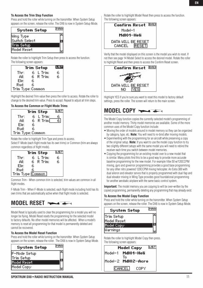
F-MODE SETUP The F-Mode setup screen is used to assign the switches that will be used for Flight Mode and Hold. Flight Mode setup is defaulted to Flight Mode -flight mode switch and Hold- Inhibited.You can assign the flight mode and hold functions to any of 9 switches including: Inhibit, Aileron D/R, Elevator D/R, Rudder D/R, Gyro switch, Flight Mode Switch, Hold and the Governor switch.
To Access the F-Mode Setup FunctionPress and hold the roller while turning on the transmitter. When System Setup appears on the screen, release the roller. The DX8 is now in System Setup Mode.
Rotate the roller to highlight F-Mode Setup then press. The following screen appears:
Highlight the Flight mode or Hold function then press to access that function. Rotate the roller to select the desired switch.
TRIM STEp The Trim Step function allows servo movement adjustment per click of trim. For example you usually want a large trim step (8 to 10) for a new model. Each click of trim will have a large amount of trim travel so you can quickly adjust an out-of-trim model in flight. Later you can use a finer trim step (1-5) to adjust for precise flight. The Trim Step function allows the trims to be common or independent in each active flight mode. Many helicopter pilots use independent trims because they are automatically active when a flight mode is activated. Important: The trim step function has no effect on the overall trim travel, only the total number of clicks available. If you select a 0 value in trim step, the trim is turned off.
EN
17SPEKTRUM DX8 • RADIO INSTRUCTION MANUAL
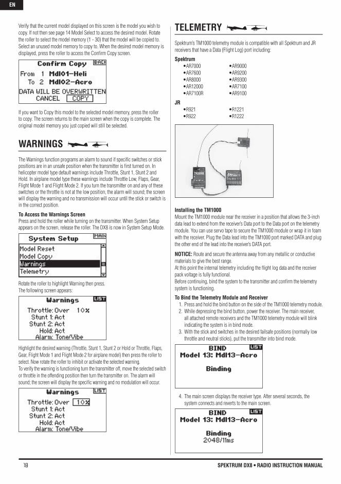
To Access the Trim Step FunctionPress and hold the roller while turning on the transmitter. When System Setup appears on the screen, release the roller. The DX8 is now in System Setup Mode.
Rotate the roller to highlight Trim Setup then press to access the function. The following screen appears:
Highlight the desired Trim value then press the roller to access. Rotate the roller to change to the desired trim value. Press to accept. Repeat to adjust all trim steps.
To Access the Common or Flight Mode Trims
Rotate the roller to highlight Trim Type and press to access.Select F-Mode (each flight mode has its own trims) or Common (trim are always common regardless of flight mode).
Common Trim - When common trim is selected, trim values are common in all flight modes.
F-Mode Trim - When F-Mode is selected, each flight mode including hold has its own trims that are automatically active when that flight mode is selected.
MODEL RESET Model Reset is typically used to clear the programming for a model you will no longer be flying. Model Reset resets the programming for the selected model to factory defaults. No other model memories will be affected. When a model’s memory is reset all programming for that model is permanently deleted and cannot be recovered.
To Access the Model Reset FunctionPress and hold the roller while turning on the transmitter. When System Setup appears on the screen, release the roller. The DX8 is now in System Setup Mode.
Rotate the roller to highlight Model Reset then press to access the function. The following screen appears:
Verify that the model displayed on this screen is the model you wish to reset. If not then see page 14 Model Select to access the desired model. Rotate the roller to highlight Reset and then press to access the Confirm Reset screen.
Highlight YES If you’re sure you want to reset this model to factory default settings, press the roller. The screen will return to the main screen.
MODEL COPY The Model Copy function copies the currently selected model’s programming of another model memory. Thirty model memories are available. Some of the more common uses of the Model Copy function include:•Movingtheorderofmodelsaroundinmodelmemorysotheycanbeorganized
by category, type, etc. Note: You will need to re-bind after moving models.•Experimentingwiththeprogrammingforanaircraftwhilepreservingacopy
of the original setup. Note: If you want to use the model copy function to try two slightly different setups with the same model you will need to rebind the receiver each time you switch between model memories.
•Copyingtheprogrammingforanexistingmodelovertoanewmodelthatis similar. Many pilots find this to be a good way to provide more accurate baseline programming for the new model. For example Vibe 50 w/120CCPM mixing, gyro and governor programming provides a good base programming for any other nitro powered 120CCPM mixing helicopter. An Extra 300 with dual aileron and elevator servos that is properly programmed with dual flap and dual elevator mixing in Wing Type provides good foundational programming for another aerobatic airplane with the same basic control system.
Important: The model memory you are copying to will be over-written by the copied programming, permanently deleting any programming that may already exist.
To Access the Model Copy FunctionPress and hold the roller while turning on the transmitter. When System Setup appears on the screen, release the roller. The DX8 is now in System Setup Mode.
Rotate the roller to highlight Model Copy then press. The following screen appears:
EN
18 SPEKTRUM DX8 • RADIO INSTRUCTION MANUAL
Verify that the current model displayed on this screen is the model you wish to copy. If not then see page 14 Model Select to access the desired model. Rotate the roller to select the model memory (1 - 30) that the model will be copied to. Select an unused model memory to copy to. When the desired model memory is displayed, press the roller to access the Confirm Copy screen.
If you want to Copy this model to the selected model memory, press the roller to copy. The screen returns to the main screen when the copy is complete. The original model memory you just copied will still be selected.
WARNINGS The Warnings function programs an alarm to sound if specific switches or stick positions are in an unsafe position when the transmitter is first turned on. In helicopter model type default warnings include Throttle, Stunt 1, Stunt 2 and Hold. In airplane model type these warnings include Throttle Low, Flaps, Gear, Flight Mode 1 and Flight Mode 2. If you turn the transmitter on and any of these switches or the throttle is not at the low position, the alarm will sound; the screen will display the warning and no transmission will occur until the stick or switch is in the correct position.
To Access the Warnings ScreenPress and hold the roller while turning on the transmitter. When System Setup appears on the screen, release the roller. The DX8 is now in System Setup Mode.
Rotate the roller to highlight Warning then press. The following screen appears:
Highlight the desired warning (Throttle, Stunt 1, Stunt 2 or Hold or Throttle, Flaps, Gear, Flight Mode 1 and Flight Mode 2 for airplane model) then press the roller to select. Now rotate the roller to inhibit or activate the selected warning.To verify the warning is functioning turn the transmitter off, move the selected switch or throttle in the offending position then turn the transmitter on. The alarm will sound; the screen will display the specific warning and no modulation will occur.
TELEMETRY Spektrum’s TM1000 telemetry module is compatible with all Spektrum and JR receivers that have a Data (Flight Log) port including:
Spektrum •AR7000 •AR9000 •AR7600 •AR9200 •AR8000 •AR9300 •AR12000 •AR7100 •AR7100R •AR9100
JR •R921 •R1221 •R922 •R1222
Installing the TM1000Mount the TM1000 module near the receiver in a position that allows the 3-inch data lead to extend from the receiver’s Data port to the Data port on the telemetry module. You can use servo tape to secure the TM1000 module or wrap it in foam with the receiver. Plug the Data lead into the TM1000 port marked DATA and plug the other end of the lead into the receiver’s DATA port.
NOTICE: Route and secure the antenna away from any metallic or conductive materials to give the best range.At this point the internal telemetry including the flight log data and the receiver pack voltage is fully functional.Before continuing, bind the system to the transmitter and confirm the telemetry system is functioning.
To bind the Telemetry Module and Receiver1. Press and hold the bind button on the side of the TM1000 telemetry module. 2. While depressing the bind button, power the receiver. The main receiver,
all attached remote receivers and the TM1000 telemetry module will blink indicating the system is in bind mode.
3. With the stick and switches in the desired failsafe positions (normally low throttle and neutral sticks), put the transmitter into bind mode.
4. The main screen displays the receiver type. After several seconds, the system connects and reverts to the main screen.
EN
19SPEKTRUM DX8 • RADIO INSTRUCTION MANUAL
5. From the main screen rotate the roller to access the telemetry screen and verify the flight log data and receiver voltage displays.
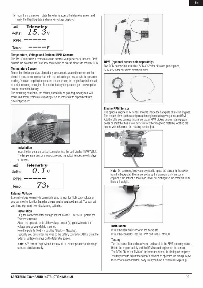
Temperature, voltage and Optional RPM SensorsThe TM1000 includes a temperature and external voltage sensors. Optional RPM sensors are available for Gas/Glow and electric brushless models to monitor RPM.
Temperature SensorTo monitor the temperature of most any component, secure the sensor on the object. It must come into contact with the surface to get an accurate temperature reading. You can loop the temperature sensor around the engine’s cylinder head to assist in tuning an engine. To monitor battery temperature, you can wrap the sensor around the battery. The mounting position of the sensor, especially on gas or glow engines, will result in different temperature readings. So it’s important to experiment with different positions.
InstallationInsert the temperature sensor connector into the port labeled TEMP/VOLT. The temperature sensor is now active and the actual temperature displays on screen.
External voltageExternal voltage telemetry is commonly used to monitor flight pack voltage or you can monitor ignition batteries on gas engine equipped aircraft. You can set warnings to prevent over-discharging batteries.
InstallationPlug the connector of the voltage sensor into the TEMP/VOLT port in the Telemetry module. Attach the opposite ends of the voltage sensor (stripped wires) to the voltage source you wish to monitor. Note the polarity (Red = + positive /Black = - Negative). Typically, you can solder the wires to the battery connector. At this point the External voltage displays on the telemetry screen.
Note: A Y-harness is provided if you want to use temperature and voltage sensors simultaneously.
RPM (optional sensor sold separately)Two RPM sensors are available: SPMA9569 for nitro and gas engines, SPMA9558 for brushless electric motors.
Engine RpM Sensor The optional engine RPM sensor mounts inside the backplate of aircraft engines. The sensor picks up the crankpin as the engine rotates giving accurate RPM. Additionally, you can use this sensor as an RPM pickup on any rotating gear/collar or shaft that has a steel setscrew or other magnetic metal by locating the sensor within 5 mm of the rotating steel object.
Note: On some engines you may need to space the sensor further away from the backplate. The sensor picks up the crankpin only; on some engines if the sensor is too close, it will not distinguish the crankpin from the crank weight.
InstallationInstall the backplate sensor in the backplate. Install the connector into the RPM port in the TM1000.
TestingTurn the transmitter and receiver on and scroll to the RPM telemetry screen. Rotate the engine rapidly and the RPM should register on the screen. The RED LED on the TM1000 indicates the sensor is picking up properly. You may need to adjust the sensor’s position to optimize the pickup. Move the sensor closer or farther away until you have a reliable RPM pickup.
EN
20 SPEKTRUM DX8 • RADIO INSTRUCTION MANUAL
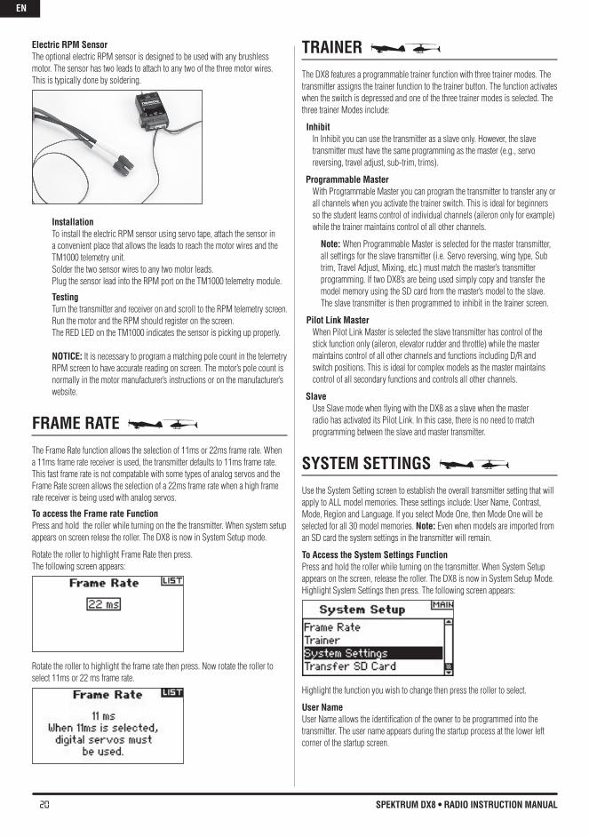
Electric RpM Sensor The optional electric RPM sensor is designed to be used with any brushless motor. The sensor has two leads to attach to any two of the three motor wires. This is typically done by soldering.
InstallationTo install the electric RPM sensor using servo tape, attach the sensor in a convenient place that allows the leads to reach the motor wires and the TM1000 telemetry unit. Solder the two sensor wires to any two motor leads. Plug the sensor lead into the RPM port on the TM1000 telemetry module.
TestingTurn the transmitter and receiver on and scroll to the RPM telemetry screen. Run the motor and the RPM should register on the screen. The RED LED on the TM1000 indicates the sensor is picking up properly.
NOTICE: It is necessary to program a matching pole count in the telemetry RPM screen to have accurate reading on screen. The motor’s pole count is normally in the motor manufacturer’s instructions or on the manufacturer’s website.
FRAME RATE The Frame Rate function allows the selection of 11ms or 22ms frame rate. When a 11ms frame rate receiver is used, the transmitter defaults to 11ms frame rate. This fast frame rate is not compatable with some types of analog servos and the Frame Rate screen allows the selection of a 22ms frame rate when a high frame rate receiver is being used with analog servos.
To access the Frame rate FunctionPress and hold the roller while turning on the the transmitter. When system setup appears on screen relese the roller. The DX8 is now in System Setup mode.
Rotate the roller to highlight Frame Rate then press. The following screen appears:
Rotate the roller to highlight the frame rate then press. Now rotate the roller to select 11ms or 22 ms frame rate.
TRAINER The DX8 features a programmable trainer function with three trainer modes. The transmitter assigns the trainer function to the trainer button. The function activates when the switch is depressed and one of the three trainer modes is selected. The three trainer Modes include:
Inhibit In Inhibit you can use the transmitter as a slave only. However, the slave transmitter must have the same programming as the master (e.g., servo reversing, travel adjust, sub-trim, trims).
Programmable MasterWith Programmable Master you can program the transmitter to transfer any or all channels when you activate the trainer switch. This is ideal for beginners so the student learns control of individual channels (aileron only for example) while the trainer maintains control of all other channels.
Note: When Programmable Master is selected for the master transmitter, all settings for the slave transmitter (i.e. Servo reversing, wing type, Sub trim, Travel Adjust, Mixing, etc.) must match the master’s transmitter programming. If two DX8’s are being used simply copy and transfer the model memory using the SD card from the master’s model to the slave. The slave transmitter is then programmed to inhibit in the trainer screen.
Pilot Link MasterWhen Pilot Link Master is selected the slave transmitter has control of the stick function only (aileron, elevator rudder and throttle) while the master maintains control of all other channels and functions including D/R and switch positions. This is ideal for complex models as the master maintains control of all secondary functions and controls all other channels.
Slave Use Slave mode when flying with the DX8 as a slave when the master radio has activated its Pilot Link. In this case, there is no need to match programming between the slave and master transmitter.
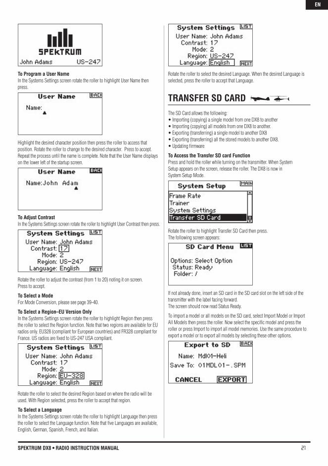
SYSTEM SETTINGS Use the System Setting screen to establish the overall transmitter setting that will apply to ALL model memories. These settings include: User Name, Contrast, Mode, Region and Language. If you select Mode One, then Mode One will be selected for all 30 model memories. Note: Even when models are imported from an SD card the system settings in the transmitter will remain.
To Access the System Settings FunctionPress and hold the roller while turning on the transmitter. When System Setup appears on the screen, release the roller. The DX8 is now in System Setup Mode.Highlight System Settings then press. The following screen appears:
Highlight the function you wish to change then press the roller to select.
User NameUser Name allows the identification of the owner to be programmed into the transmitter. The user name appears during the startup process at the lower left corner of the startup screen.
EN
21SPEKTRUM DX8 • RADIO INSTRUCTION MANUAL
To program a User NameIn the Systems Settings screen rotate the roller to highlight User Name then press.
Highlight the desired character position then press the roller to access that position. Rotate the roller to change to the desired character. Press to accept.Repeat the process until the name is complete. Note that the User Name displays on the lower left of the startup screen.
To Adjust ContrastIn the Systems Settings screen rotate the roller to highlight User Contrast then press.
Rotate the roller to adjust the contrast (from 1 to 20) noting it on screen. Press to accept.
To Select a Mode For Mode Conversion, please see page 39-40.
To Select a Region–EU version OnlyIn the Systems Settings screen rotate the roller to highlight Region then press the roller to select the Region function. Note that two regions are available for EU radios only. EU328 (compliant for European countries) and FR328 compliant for France. US radios are fixed to US-247 USA compliant.
Rotate the roller to select the desired Region based on where the radio will be used. With Region selected, press the roller to accept that region.
To Select a LanguageIn the Systems Settings screen rotate the roller to highlight Language then press the roller to select the Language function. Note that five Languages are available, English, German, Spanish, French, and Italian.
Rotate the roller to select the desired Language. When the desired Language is selected, press the roller to accept that Language.
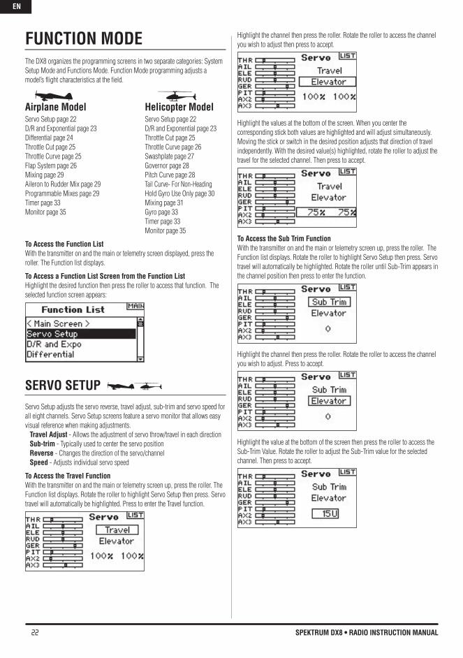
TRANSFER SD CARD The SD Card allows the following:•Importing(copying)asinglemodelfromoneDX8toanother•Importing(copying)allmodelsfromoneDX8toanother.•Exporting(transferring)asinglemodeltoanotherDX8•Exporting(transferring)allthestoredmodelstoanotherDX8.•Updatingfirmware
To Access the Transfer SD card FunctionPress and hold the roller while turning on the transmitter. When SystemSetup appears on the screen, release the roller. The DX8 is now inSystem Setup Mode.
Rotate the roller to highlight Transfer SD Card then press. The following screen appears:
If not already done, insert an SD card in the SD card slot on the left side of the transmitter with the label facing forward.The screen should now read Status Ready.
To import a model or all models on the SD card, select Import Model or Import All Models then press the roller. Now select the specific model and press the roller or press Import to import all model memories. Use the same procedure to export a model or to export all models by selecting these other options.
EN
22 SPEKTRUM DX8 • RADIO INSTRUCTION MANUAL
FUNCTION MODEThe DX8 organizes the programming screens in two separate categories: System Setup Mode and Functions Mode. Function Mode programming adjusts a model’s flight characteristics at the field.
Airplane Model helicopter ModelServo Setup page 22 Servo Setup page 22D/R and Exponential page 23 D/R and Exponential page 23Differential page 24 Throttle Cut page 25Throttle Cut page 25 Throttle Curve page 26Throttle Curve page 25 Swashplate page 27Flap System page 26 Governor page 28Mixing page 29 Pitch Curve page 28Aileron to Rudder Mix page 29 Tail Curve- For Non-Heading Programmable Mixes page 29 Hold Gyro Use Only page 30 Timer page 33 Mixing page 31Monitor page 35 Gyro page 33 Timer page 33 Monitor page 35
To Access the Function ListWith the transmitter on and the main or telemetry screen displayed, press the roller. The Function list displays.
To Access a Function List Screen from the Function ListHighlight the desired function then press the roller to access that function. The selected function screen appears:
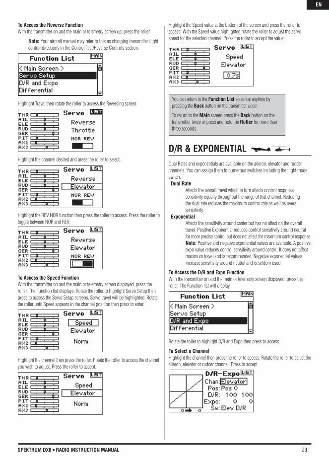
SERvO SETUP Servo Setup adjusts the servo reverse, travel adjust, sub-trim and servo speed for all eight channels. Servo Setup screens feature a servo monitor that allows easy visual reference when making adjustments. Travel Adjust - Allows the adjustment of servo throw/travel in each direction Sub-trim - Typically used to center the servo position Reverse - Changes the direction of the servo/channel Speed - Adjusts individual servo speed
To Access the Travel Function With the transmitter on and the main or telemetry screen up, press the roller. The Function list displays. Rotate the roller to highlight Servo Setup then press. Servo travel will automatically be highlighted. Press to enter the Travel function.
Highlight the channel then press the roller. Rotate the roller to access the channel you wish to adjust then press to accept.
Highlight the values at the bottom of the screen. When you center the corresponding stick both values are highlighted and will adjust simultaneously. Moving the stick or switch in the desired position adjusts that direction of travel independently. With the desired value(s) highlighted, rotate the roller to adjust the travel for the selected channel. Then press to accept.
To Access the Sub Trim Function With the transmitter on and the main or telemetry screen up, press the roller. The Function list displays. Rotate the roller to highlight Servo Setup then press. Servo travel will automatically be highlighted. Rotate the roller until Sub-Trim appears in the channel position then press to enter the function.
Highlight the channel then press the roller. Rotate the roller to access the channel you wish to adjust. Press to accept.
Highlight the value at the bottom of the screen then press the roller to access the Sub-Trim Value. Rotate the roller to adjust the Sub-Trim value for the selected channel. Then press to accept.
EN
23SPEKTRUM DX8 • RADIO INSTRUCTION MANUAL
To Access the Reverse Function With the transmitter on and the main or telemetry screen up, press the roller.
Note: Your aircraft manual may refer to this as changing transmitter flight control directions in the Control Test/Reverse Controls section.
Highlight Travel then rotate the roller to access the Reversing screen.
Highlight the channel desired and press the roller to select.
Highlight the REV NOR function then press the roller to access. Press the roller to toggle between NOR and REV.
To Access the Speed Function With the transmitter on and the main or telemetry screen displayed, press the roller. The Function list displays. Rotate the roller to highlight Servo Setup then press to access the Servo Setup screens. Servo travel will be highlighted. Rotate the roller until Speed appears in the channel position then press to enter.
Highlight the channel then press the roller. Rotate the roller to access the channel you wish to adjust. Press the roller to accept.
Highlight the Speed value at the bottom of the screen and press the roller to access. With the Speed value highlighted rotate the roller to adjust the servo speed for the selected channel. Press the roller to accept the value.
D/R & EXPONENTIAL Dual Rates and exponentials are available on the aileron, elevator and rudder channels. You can assign them to numerous switches including the flight mode switch. Dual Rate Affects the overall travel which in turn affects control response
sensitivity equally throughout the range of that channel. Reducing the dual rate reduces the maximum control rate as well as overall sensitivity.
Exponential Affects the sensitivity around center but has no affect on the overall
travel. Positive Exponential reduces control sensitivity around neutral for more precise control but does not affect the maximum control response. Note: Positive and negative exponential values are available. A positive expo value reduces control sensitivity around center. It does not affect maximum travel and is recommended. Negative exponential values increase sensitivity around neutral and is seldom used.
To Access the D/R and Expo Function With the transmitter on and the main or telemetry screen displayed, press the roller. The Function list will display.
Rotate the roller to highlight D/R and Expo then press to access.
To Select a Channel Highlight the channel then press the roller to access. Rotate the roller to select the aileron, elevator or rudder channel. Press to accept.
You can return to the Function List screen at anytime by pressing the back button on the transmitter once.
To return to the Main screen press the back button on the transmitter twice or press and hold the Roller for more than three seconds.
EN
24 SPEKTRUM DX8 • RADIO INSTRUCTION MANUAL
To Select SwitchRotate the roller to highlight Sw (switch) then press to access the switch options. Select the desired switch to change the dual rate for that channel or inhibit then press the roller to make it active.
Note: You can assign multiple channels to a single switch to affect the dual and exponential rates of all.
To Select Switch Position to AdjustNote Pos: Pos 0 in the center of the screen. Move the switch displayed at the bottom of the screen to one of three positions from 0,1,2. When you make D/R or Expo adjustments, values are assigned and automatically active when the switch is in that position (Pos 0, 1or 2).
To Select D/R and Expo valuesConfirm that the desired channel and switch position are selected. Rotate the roller to highlight the D/R or Expo value then press to access. When the corresponding channel’s control stick is centered both values are highlighted. If you move the control stick to its endpoint, only one value will be highlighted.
This allows the D/R or Expo value in that direction only to change. With the desired value selected, rotate the roller to select.
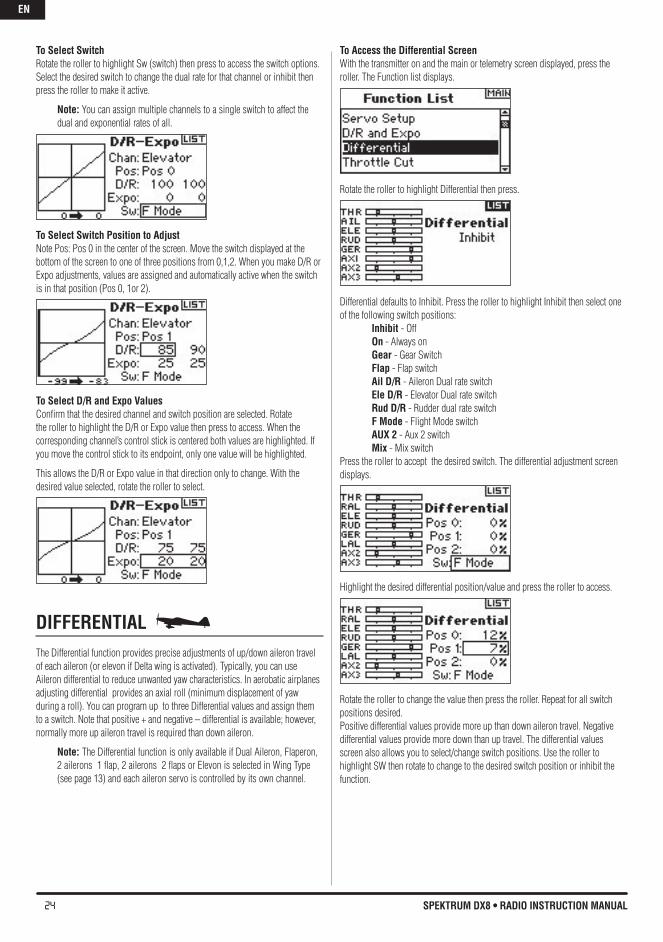
DIFFERENTIAL The Differential function provides precise adjustments of up/down aileron travel of each aileron (or elevon if Delta wing is activated). Typically, you can use Aileron differential to reduce unwanted yaw characteristics. In aerobatic airplanes adjusting differential provides an axial roll (minimum displacement of yaw during a roll). You can program up to three Differential values and assign them to a switch. Note that positive + and negative – differential is available; however, normally more up aileron travel is required than down aileron.
Note: The Differential function is only available if Dual Aileron, Flaperon, 2 ailerons 1 flap, 2 ailerons 2 flaps or Elevon is selected in Wing Type (see page 13) and each aileron servo is controlled by its own channel.
To Access the Differential ScreenWith the transmitter on and the main or telemetry screen displayed, press the roller. The Function list displays.
Rotate the roller to highlight Differential then press.
Differential defaults to Inhibit. Press the roller to highlight Inhibit then select one of the following switch positions: Inhibit - Off On - Always on Gear - Gear Switch Flap - Flap switch Ail D/R - Aileron Dual rate switch Ele D/R - Elevator Dual rate switch Rud D/R - Rudder dual rate switch F Mode - Flight Mode switch AUX 2 - Aux 2 switch Mix - Mix switchPress the roller to accept the desired switch. The differential adjustment screen displays.
Highlight the desired differential position/value and press the roller to access.
Rotate the roller to change the value then press the roller. Repeat for all switch positions desired.Positive differential values provide more up than down aileron travel. Negative differential values provide more down than up travel. The differential values screen also allows you to select/change switch positions. Use the roller to highlight SW then rotate to change to the desired switch position or inhibit the function.
EN
25SPEKTRUM DX8 • RADIO INSTRUCTION MANUAL
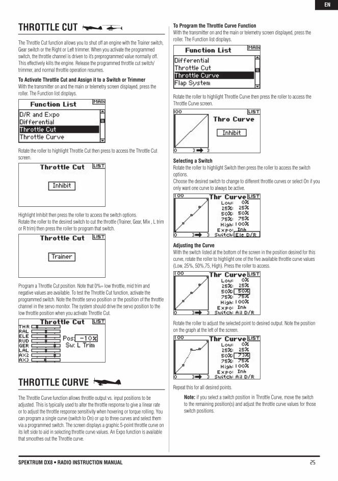
ThROTTLE CUT The Throttle Cut function allows you to shut off an engine with the Trainer switch, Gear switch or the Right or Left trimmer. When you activate the programmed switch, the throttle channel is driven to it’s preprogrammed value normally off. This effectively kills the engine. Release the programmed throttle cut switch/trimmer, and normal throttle operation resumes.
To Activate Throttle Cut and Assign it to a Switch or TrimmerWith the transmitter on and the main or telemetry screen displayed, press the roller. The Function list displays.
Rotate the roller to highlight Throttle Cut then press to access the Throttle Cut screen.
Highlight Inhibit then press the roller to access the switch options.Rotate the roller to the desired switch to cut the throttle (Trainer, Gear, Mix , L trim or R trim) then press the roller to program that switch.
Program a Throttle Cut position. Note that 0%= low throttle, mid trim and negative values are available. To test the Throttle Cut function, activate the programmed switch. Note the throttle servo position or the position of the throttle channel in the servo monitor. The system should drive the servo position to the low throttle position when you activate Throttle Cut.
ThROTTLE CURvE The Throttle Curve function allows throttle output vs. input positions to be adjusted. This is typically used to alter the throttle response to give a linear rate or to adjust the throttle response sensitivity when hovering or torque rolling. You can program a single curve (switch to On) or up to three curves and select them via a programmed switch. The screen displays a graphic 5-point throttle curve on its left side to aid in selecting throttle curve values. An Expo function is available that smoothes out the Throttle curve.
To Program the Throttle Curve FunctionWith the transmitter on and the main or telemetry screen displayed, press the roller. The Function list displays.
Rotate the roller to highlight Throttle Curve then press the roller to access the Throttle Curve screen.
Selecting a SwitchRotate the roller to highlight Switch then press the roller to access the switch options.Choose the desired switch to change to different throttle curves or select On if you only want one curve to always be active.
Adjusting the CurveWith the switch listed at the bottom of the screen in the position desired for this curve, rotate the roller to highlight one of the five available throttle curve values (Low, 25%, 50%,75, High). Press the roller to access.
Rotate the roller to adjust the selected point to desired output. Note the position on the graph at the left of the screen.
Repeat this for all desired points.
Note: if you select a switch position in Throttle Curve, move the switch to the remaining position(s) and adjust the throttle curve values for those switch positions.
EN
26 SPEKTRUM DX8 • RADIO INSTRUCTION MANUAL
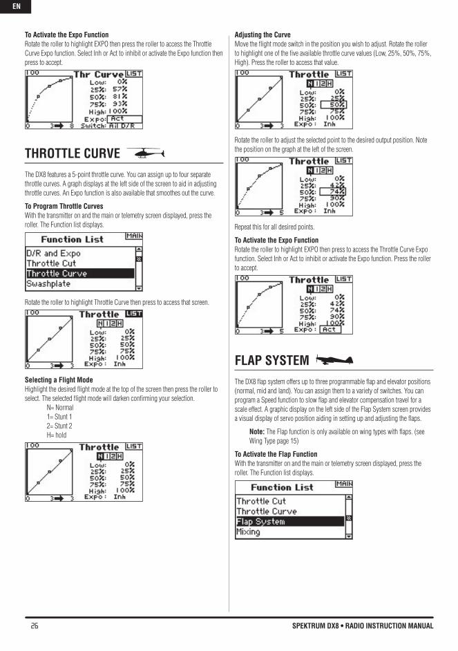
To Activate the Expo Function Rotate the roller to highlight EXPO then press the roller to access the Throttle Curve Expo function. Select Inh or Act to inhibit or activate the Expo function then press to accept.
ThROTTLE CURvE The DX8 features a 5-point throttle curve. You can assign up to four separate throttle curves. A graph displays at the left side of the screen to aid in adjusting throttle curves. An Expo function is also available that smoothes out the curve.
To Program Throttle CurvesWith the transmitter on and the main or telemetry screen displayed, press the roller. The Function list displays.
Rotate the roller to highlight Throttle Curve then press to access that screen.
Selecting a Flight ModeHighlight the desired flight mode at the top of the screen then press the roller to select. The selected flight mode will darken confirming your selection. N= Normal 1= Stunt 1 2= Stunt 2 H= hold
Adjusting the CurveMove the flight mode switch in the position you wish to adjust. Rotate the roller to highlight one of the five available throttle curve values (Low, 25%, 50%, 75%, High). Press the roller to access that value.
Rotate the roller to adjust the selected point to the desired output position. Note the position on the graph at the left of the screen.
Repeat this for all desired points.
To Activate the Expo Function Rotate the roller to highlight EXPO then press to access the Throttle Curve Expo function. Select Inh or Act to inhibit or activate the Expo function. Press the roller to accept.
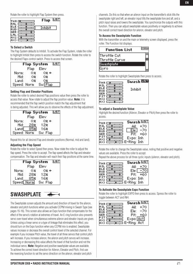
FLAP SYSTEM The DX8 flap system offers up to three programmable flap and elevator positions (normal, mid and land). You can assign them to a variety of switches. You can program a Speed function to slow flap and elevator compensation travel for a scale effect. A graphic display on the left side of the Flap System screen provides a visual display of servo position aiding in setting up and adjusting the flaps.
Note: The Flap function is only available on wing types with flaps. (see Wing Type page 15)
To Activate the Flap FunctionWith the transmitter on and the main or telemetry screen displayed, press the roller. The Function list displays.
EN
27SPEKTRUM DX8 • RADIO INSTRUCTION MANUAL
Rotate the roller to highlight Flap System then press.
To Select a Switch The Flap System defaults to Inhibit. To activate the Flap System, rotate the roller to highlight Inhibit then press to access the switch function. Rotate the roller to the desired Flaps control switch. Press to access that screen.
Setting Flap and Elevator PositionsRotate the roller to select desired Flap positions value then press the roller toaccess that value. Now rotate to adjust the flap position value. Note: it is recommended that the flap switch position match the flap adjustment that is being adjusted. This will allow you to observe the effects of the flap adjustment.
Repeat this for all desired Flap and elevator positions (Normal, mid and land).
Adjusting the Flap SpeedRotate the roller to select Speed then press. Now rotate the roller to adjust the flap speed. Press the roller to accept. The flap speed affects the flap and elevator compensation. The flap and elevator will reach their flap positions at the same time.
SWAShPLATE The Swashplate screen adjusts the amount and direction of travel for the aileron, elevator and pitch functions when you activate CCPM mixing in Swash Type (see pages 15-16). This screen also allows an Expo function that compensates for the effect of the servo’s rotation at extremes of travel. An E-ring function also prevents servo over-travel when simultaneous extreme aileron and elevator inputs are given. Unless using a linear servo or a type of linkage that eliminates this effect, you should turn on the Expo function when any CCPM mix is enabled. Swashplate values increase or decrease the overall control travel of the selected channel. For example if you increase Pitch value, the travel of all three servos that control pitch will increase. If you increase aileron, the aileron and pitch servos will increase. Increasing or decreasing this value affects the travel of that function and not the individual servo. Note: Negative and positive swashplate values are available. To achieve the correct travel direction for Aileron, Elevator and Pitch, first use the reversing function to set the servo direction on the aileron, elevator and pitch
channels. Do this so that when an aileron input on the transmitter’s stick tilts the swashplate right and left, an elevator input tilts the swashplate fore and aft, and a pitch input raises and lowers the swashplate. You synchronize the outputs with this function. Then you can adjust swashplate values positively or negatively to achieve the overall correct travel direction for aileron, elevator and pitch.
To Access the Swashplate Function With the transmitter on and the main or telemetry screen displayed, press the roller. The Function list displays.
Rotate the roller to highlight Swashplate then press to access.
To adjust a Swashplate valueHighlight the desired function (Aileron, Elevator or Pitch) then press the roller to access.
Rotate the roller to change the Swashplate value, noting that positive and negative values are available. Press the roller to accept. Repeat the above process for all three cyclic inputs (aileron, elevator and pitch).
To Activate the Swashplate Expo Function Rotate the roller to highlight EXPO then press to access. Spress the roller to toggle between ACT and INH.
EN
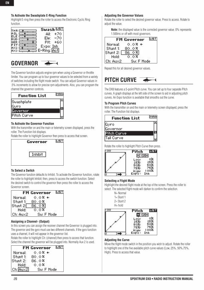
28 SPEKTRUM DX8 • RADIO INSTRUCTION MANUAL
To Activate the Swashplate E-Ring Function Highlight E-ring then press the roller to access the Electronic Cyclic Ring function.
GOvERNOR The Governor function adjusts engine rpm when using a Governor or throttle limiter. You can program up to four governor values to be selected from a variety of switches including the flight mode switch. You can adjust Governor values in .5% increments to allow for precise rpm adjustments. Also, you can program the channel the governor controls.
To Activate the Governor FunctionWith the transmitter on and the main or telemetry screen displayed, press the roller. The Function list displays.Rotate the roller to highlight Governor then press to access that screen.
To Select a Switch The Governor function defaults to Inhibit. To activate the Governor function, rotate the roller to highlight Inhibit; then, press to access the switch function. Select the desired switch to control the governor then press the roller to access the Governor screen.
Assigning a Channel- (Output)In this screen you can assign the receiver channel the Governor is plugged into. The governor and the gyro must use two different channels. If the gyro function uses a channel, it will not appear in the governor list. Rotate the roller to highlight Ch: (channel) then press to access that function. Select the channel the governor will be plugged into. Normally Aux 2 is used.
Adjusting the Governor valuesRotate the roller to select the desired governor value. Press to access. Rotate to adjust the value.
Note: the displayed value is the corrected governor value. 0% represents 1.500ms or off with most governors.
Repeat this for all desired governor values.
PITCh CURvE The DX8 features a 5-point Pitch curve. You can set up to four separate Pitch curves. A graph displays at the left side of the screen to aid in adjusting pitch curves. An Expo function is available that smooths out the curve.
To Program Pitch CurvesWith the transmitter on and the main or telemetry screen displayed, press the roller. The Function list displays.
Rotate the roller to highlight Pitch Curve then press.
Selecting a Flight ModeHighlight the desired flight mode at the top of the screen. Press the roller to select. The selected flight mode will darken to confirm the selection. N= Normal 1= Stunt 1 2= Stunt 2 H= hold
Adjusting the CurveMove the flight mode switch in the position you wish to adjust. Rotate the roller to highlight one of the five available pitch curve values (Low, 25%, 50%,75%, High). Press to access that value.
EN
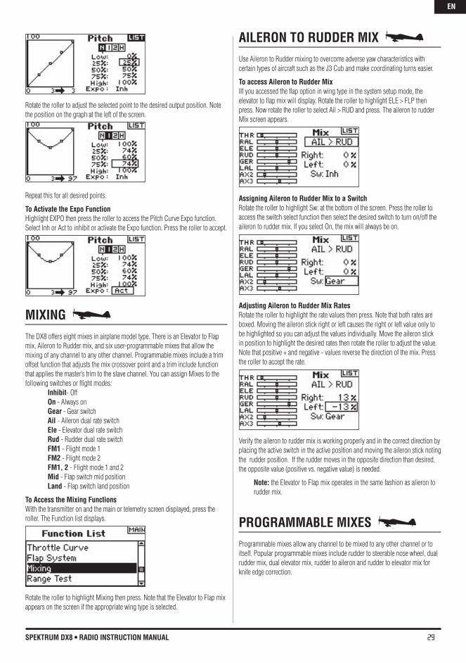
29SPEKTRUM DX8 • RADIO INSTRUCTION MANUAL
Rotate the roller to adjust the selected point to the desired output position. Note the position on the graph at the left of the screen.
Repeat this for all desired points.
To Activate the Expo Function Highlight EXPO then press the roller to access the Pitch Curve Expo function. Select Inh or Act to inhibit or activate the Expo function. Press the roller to accept.
MIXING The DX8 offers eight mixes in airplane model type. There is an Elevator to Flap mix, Aileron to Rudder mix, and six user-programmable mixes that allow the mixing of any channel to any other channel. Programmable mixes include a trim offset function that adjusts the mix crossover point and a trim include function that applies the master’s trim to the slave channel. You can assign Mixes to the following switches or flight modes: Inhibit- Off On - Always on Gear - Gear switch Ail - Aileron dual rate switch Ele - Elevator dual rate switch Rud - Rudder dual rate switch FM1 - Flight mode 1 FM2 - Flight mode 2 FM1, 2 - Flight mode 1 and 2 Mid - Flap switch mid position Land - Flap switch land position
To Access the Mixing FunctionsWith the transmitter on and the main or telemetry screen displayed, press the roller. The Function list displays.
Rotate the roller to highlight Mixing then press. Note that the Elevator to Flap mix appears on the screen if the appropriate wing type is selected.
AILERON TO RUDDER MIX Use Aileron to Rudder mixing to overcome adverse yaw characteristics with certain types of aircraft such as the J3 Cub and make coordinating turns easier.
To access Aileron to Rudder Mix IIf you accessed the flap option in wing type in the system setup mode, the elevator to flap mix will display. Rotate the roller to highlight ELE > FLP then press. Now rotate the roller to select Ail > RUD and press. The aileron to rudder Mix screen appears.
Assigning Aileron to Rudder Mix to a Switch Rotate the roller to highlight Sw: at the bottom of the screen. Press the roller to access the switch select function then select the desired switch to turn on/off the aileron to rudder mix. If you select On, the mix will always be on.
Adjusting Aileron to Rudder Mix RatesRotate the roller to highlight the rate values then press. Note that both rates are boxed. Moving the aileron stick right or left causes the right or left value only to be highlighted so you can adjust the values individually. Move the aileron stick in position to highlight the desired rates then rotate the roller to adjust the value. Note that positive + and negative - values reverse the direction of the mix. Press the roller to accept the rate.
Verify the aileron to rudder mix is working properly and in the correct direction by placing the active switch in the active position and moving the aileron stick noting the rudder position. If the rudder moves in the opposite direction than desired, the opposite value (positive vs. negative value) is needed.
Note: the Elevator to Flap mix operates in the same fashion as alieron to rudder mix.
PROGRAMMAbLE MIXES Programmable mixes allow any channel to be mixed to any other channel or to itself. Popular programmable mixes include rudder to steerable nose wheel, dual rudder mix, dual elevator mix, rudder to aileron and rudder to elevator mix for knife edge correction.
EN
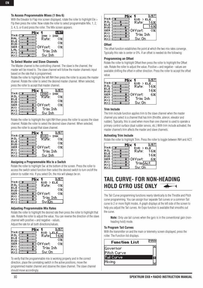
30 SPEKTRUM DX8 • RADIO INSTRUCTION MANUAL
To Access Programmable Mixes (1 thru 6) With the Elevator to Flap mix screen displayed, rotate the roller to highlight Ele > Flp then press the roller. Now rotate the roller to select programmable Mix, 1, 2, 3, 4, 5, or 6 and press the roller. The Mix screen appears.
To Select Master and Slave ChannelsThe Master channel is the controlling channel. The slave is the channel, the master will be mixed to. The slave channel will follow the master channels input based on the rate that is programmed.Rotate the roller to highlight the left INH then press the roller to access the master channel. Rotate the roller to select the desired master channel. When selected, press the roller to accept that master channel.
Rotate the roller to highlight the right INH then press the roller to access the slave channel. Rotate the roller to select the desired slave channel. When selected, press the roller to accept that slave channel.
Assigning a Programmable Mix to a Switch Rotate the roller to highlight Sw: at the bottom of the screen. Press the roller to access the switch select function then select the desired switch to turn on/off the aileron to rudder mix. If you select On, the mix will always be on.
Adjusting Programmable Mix RatesRotate the roller to highlight the desired rate then press the roller to highlight that rate. Rotate the roller to adjust the value. You can reverse the direction of the slave channel with positive + and negative - values.Adjust the rate for all both directions/values.
To verify that the programmable mix is working properly and in the correct direction, place the correlating switch in the active positions, move the programmed master channel and observe the slave channel. The slave channel should move accordingly.
OffsetThe offset function establishes the point at which the two mix rates converge. Typically this rate is center or 0%. If an offset is needed do the following:
Programming an OffsetRotate the roller to highlight Offset then press the roller to highlight the Offset rate. Rotate the roller to adjust the value. Positive + and negative - values are available shifting the offset in either direction. Press the roller to accept the offset value.
Trim IncludeThe trim include function applies trim to the slave channel when the master channel you select is a channel that has trim (throttle, aileron, elevator and rudder). Typically, this is used when more than one channel is used to operate a primary control surface (dual rudder servos, etc.) With trim include activated, the master channel’s trim affects the master and slave channels.
Activating Trim IncludeRotate the roller to highlight Trim. Press the roller to toggle between INH and ACT.
TAIL CURvE- FOR NON-hEADING hOLD GYRO USE ONLY The Tail Curve programming functions nearly identically to the Throttle and Pitch curve programming. You can assign four separate Tail curves or a common Tail curve to 2 or more flight modes. A graph displays at the left side of the screen to help you adjust the Tail curves. An Expo function is available that smooths out the curve.
Note: Only use tail curves when the gyro is in the conventional gain (non-heading hold) mode.
To Program Tail CurvesWith the transmitter on and the main or telemetry screen displayed, press the roller. The Function list displays.
EN
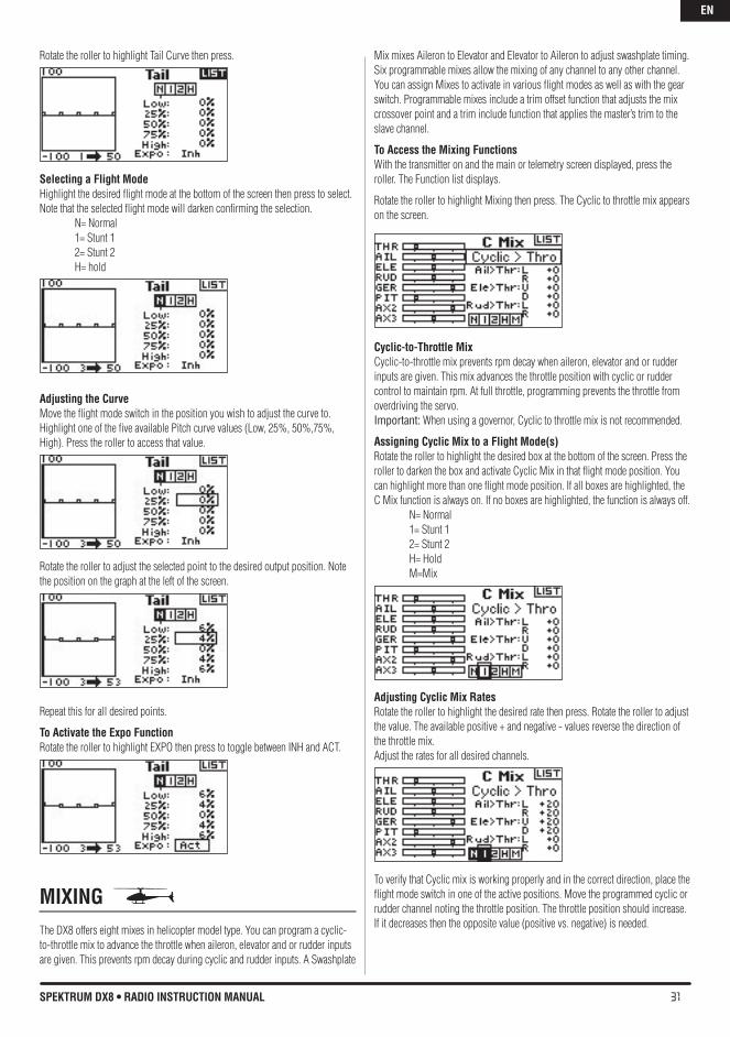
31SPEKTRUM DX8 • RADIO INSTRUCTION MANUAL
Rotate the roller to highlight Tail Curve then press.
Selecting a Flight ModeHighlight the desired flight mode at the bottom of the screen then press to select. Note that the selected flight mode will darken confirming the selection. N= Normal 1= Stunt 1 2= Stunt 2 H= hold
Adjusting the CurveMove the flight mode switch in the position you wish to adjust the curve to. Highlight one of the five available Pitch curve values (Low, 25%, 50%,75%, High). Press the roller to access that value.
Rotate the roller to adjust the selected point to the desired output position. Note the position on the graph at the left of the screen.
Repeat this for all desired points.
To Activate the Expo Function Rotate the roller to highlight EXPO then press to toggle between INH and ACT.
MIXING The DX8 offers eight mixes in helicopter model type. You can program a cyclic-to-throttle mix to advance the throttle when aileron, elevator and or rudder inputs are given. This prevents rpm decay during cyclic and rudder inputs. A Swashplate
Mix mixes Aileron to Elevator and Elevator to Aileron to adjust swashplate timing. Six programmable mixes allow the mixing of any channel to any other channel. You can assign Mixes to activate in various flight modes as well as with the gear switch. Programmable mixes include a trim offset function that adjusts the mix crossover point and a trim include function that applies the master’s trim to the slave channel.
To Access the Mixing FunctionsWith the transmitter on and the main or telemetry screen displayed, press the roller. The Function list displays.
Rotate the roller to highlight Mixing then press. The Cyclic to throttle mix appears on the screen.
Cyclic-to-Throttle MixCyclic-to-throttle mix prevents rpm decay when aileron, elevator and or rudder inputs are given. This mix advances the throttle position with cyclic or rudder control to maintain rpm. At full throttle, programming prevents the throttle from overdriving the servo. Important: When using a governor, Cyclic to throttle mix is not recommended.
Assigning Cyclic Mix to a Flight Mode(s) Rotate the roller to highlight the desired box at the bottom of the screen. Press the roller to darken the box and activate Cyclic Mix in that flight mode position. You can highlight more than one flight mode position. If all boxes are highlighted, the C Mix function is always on. If no boxes are highlighted, the function is always off. N= Normal 1= Stunt 1 2= Stunt 2 H= Hold M=Mix
Adjusting Cyclic Mix RatesRotate the roller to highlight the desired rate then press. Rotate the roller to adjust the value. The available positive + and negative - values reverse the direction of the throttle mix.Adjust the rates for all desired channels.
To verify that Cyclic mix is working properly and in the correct direction, place the flight mode switch in one of the active positions. Move the programmed cyclic or rudder channel noting the throttle position. The throttle position should increase. If it decreases then the opposite value (positive vs. negative) is needed.
EN
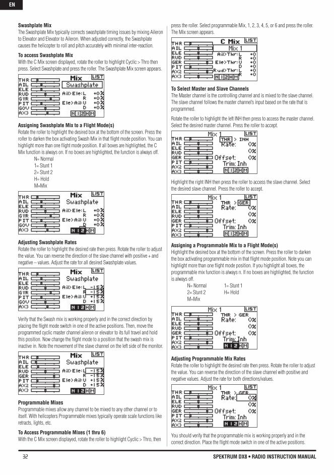
32 SPEKTRUM DX8 • RADIO INSTRUCTION MANUAL
Swashplate MixThe Swashplate Mix typically corrects swashplate timing issues by mixing Aileron to Elevator and Elevator to Aileron. When adjusted correctly, the Swashplate causes the helicopter to roll and pitch accurately with minimal inter-reaction.
To access Swashplate Mix With the C Mix screen displayed, rotate the roller to highlight Cyclic > Thro then press. Select Swashplate and press the roller. The Swashplate Mix screen appears.
Assigning Swashplate Mix to a Flight Mode(s) Rotate the roller to highlight the desired box at the bottom of the screen. Press the roller to darken the box activating Swash Mix in that flight mode position. You can highlight more than one flight mode position. If all boxes are highlighted, the C Mix function is always on. If no boxes are highlighted, the function is always off. N= Normal 1= Stunt 1 2= Stunt 2 H= Hold M=Mix
Adjusting Swashplate RatesRotate the roller to highlight the desired rate then press. Rotate the roller to adjust the value. You can reverse the direction of the slave channel with positive + and negative – values. Adjust the rate for all desired Swashplate values.
Verify that the Swash mix is working properly and in the correct direction by placing the flight mode switch in one of the active positions. Then, move the programmed cyclic master channel aileron or elevator to its full travel and hold this position. Now change the flight mode to a position that the swash mix is inactive in. Note the movement of the slave channel on the left side of the monitor.
Programmable MixesProgrammable mixes allow any channel to be mixed to any other channel or to itself. With helicopters Programmable mixes typically operate scale functions like retracts, lights, etc.
To Access Programmable Mixes (1 thru 6) With the C Mix screen displayed, rotate the roller to highlight Cyclic > Thro, then
press the roller. Select programmable Mix, 1, 2, 3, 4, 5, or 6 and press the roller. The Mix screen appears.
To Select Master and Slave ChannelsThe Master channel is the controlling channel and is mixed to the slave channel. The slave channel follows the master channel’s input based on the rate that is programmed.
Rotate the roller to highlight the left INH then press to access the master channel. Select the desired master channel. Press the roller to accept.
Highlight the right INH then press the roller to access the slave channel. Select the desired slave channel. Press the roller to accept.
Assigning a Programmable Mix to a Flight Mode(s) Highlight the desired box at the bottom of the screen. Press the roller to darken the box activating programmable mix in that flight mode position. Note you can highlight more than one flight mode position. If you highlight all boxes, the programmable mix function is always n. If no boxes are highlighted, the function is always off. N= Normal 1= Stunt 1 2= Stunt 2 H= Hold M=Mix
Adjusting Programmable Mix RatesRotate the roller to highlight the desired rate then press. Rotate the roller to adjust the value. You can reverse the direction of the slave channel with positive and negative values. Adjust the rate for both directions/values.
You should verify that the programmable mix is working properly and in the correct direction. Place the flight mode switch in one of the active positions.
EN
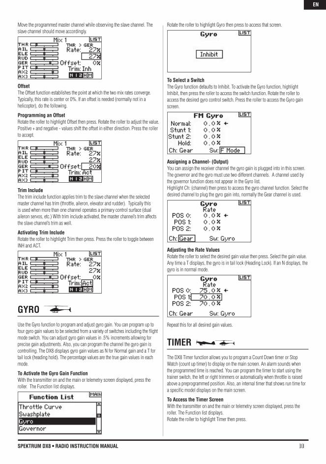
33SPEKTRUM DX8 • RADIO INSTRUCTION MANUAL
Move the programmed master channel while observing the slave channel. The slave channel should move accordingly.
OffsetThe Offset function establishes the point at which the two mix rates converge. Typically, this rate is center or 0%. If an offset is needed (normally not in a helicopter), do the following.
Programming an OffsetRotate the roller to highlight Offset then press. Rotate the roller to adjust the value. Positive + and negative - values shift the offset in either direction. Press the roller to accept.
Trim IncludeThe trim include function applies trim to the slave channel when the selected master channel has trim (throttle, aileron, elevator and rudder). Typically this is used when more than one channel operates a primary control surface (dual aileron servos, etc.) With trim include activated, the master channel’s trim affects the slave channel’s trim as well.
Activating Trim IncludeRotate the roller to highlight Trim then press. Press the roller to toggle between INH and ACT.
GYRO Use the Gyro function to program and adjust gyro gain. You can program up to four gyro gain values to be selected from a variety of switches including the flight mode switch. You can adjust gyro gain values in .5% increments allowing for precise gain adjustments. Also, you can program the channel the gyro gain is controlling. The DX8 displays gyro gain values as N for Normal gain and a T for tail lock (heading hold). The percentage values are the true gain values in each mode.
To Activate the Gyro Gain FunctionWith the transmitter on and the main or telemetry screen displayed, press the roller. The Function list displays.
Rotate the roller to highlight Gyro then press to access that screen.
To Select a Switch The Gyro function defaults to Inhibit. To activate the Gyro function, highlight Inhibit, then press the roller to access the switch function. Rotate the roller to access the desired gyro control switch. Press the roller to access the Gyro gain screen.
Assigning a Channel- (Output)You can assign the receiver channel the gyro gain is plugged into in this screen. The governor and the gyro must use two different channels. A channel used by the governor function does not appear in the Gyro list. Highlight Ch: (channel) then press to access the gyro channel function. Select the desired channel to plug the gyro gain into, normally the Gear channel is used.
Adjusting the Rate valuesRotate the roller to select the desired gain value then press. Select the gain value. Any time a T displays, the gyro is in tail lock (Heading Lock). If an N displays, the gyro is in normal mode.
Repeat this for all desired gain values.
TIMER The DX8 Timer function allows you to program a Count Down timer or Stop Watch (count up timer) to display on the main screen. An alarm sounds when the programmed time is reached. You can program the timer to start using the trainer switch, the left or right trimmers or automatically when throttle is raised above a preprogrammed position. Also, an internal timer that shows run time for a specific model displays on the main screen.
To Access the Timer ScreenWith the transmitter on and the main or telemetry screen displayed, press the roller. The Function list displays.Rotate the roller to highlight Timer then press.
EN
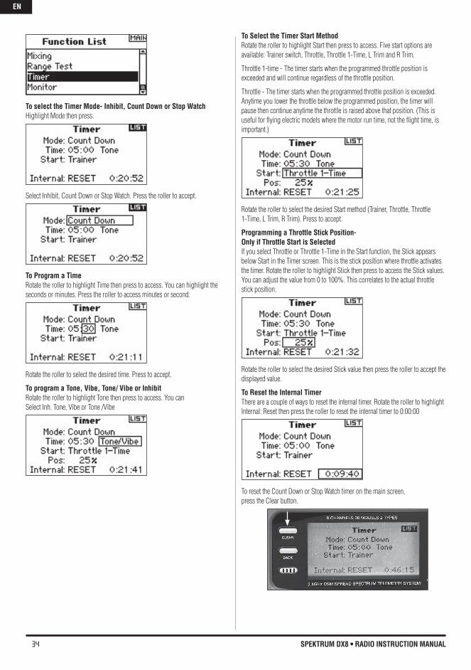
34 SPEKTRUM DX8 • RADIO INSTRUCTION MANUAL
To select the Timer Mode- Inhibit, Count Down or Stop WatchHighlight Mode then press.
Select Inhibit, Count Down or Stop Watch. Press the roller to accept.
To program a TimeRotate the roller to highlight Time then press to access. You can highlight the seconds or minutes. Press the roller to access minutes or second.
Rotate the roller to select the desired time. Press to accept.
To program a Tone, vibe, Tone/ vibe or InhibitRotate the roller to highlight Tone then press to access. You canSelect Inh. Tone, Vibe or Tone /Vibe
To Select the Timer Start MethodRotate the roller to highlight Start then press to access. Five start options are available: Trainer switch, Throttle, Throttle 1-Time, L Trim and R Trim.
Throttle 1-time - The timer starts when the programmed throttle position is exceeded and will continue regardless of the throttle position.
Throttle - The timer starts when the programmed throttle position is exceeded. Anytime you lower the throttle below the programmed position, the timer will pause then continue anytime the throttle is raised above that position. (This is useful for flying electric models where the motor run time, not the flight time, is important.)
Rotate the roller to select the desired Start method (Trainer, Throttle, Throttle 1-Time, L Trim, R Trim). Press to accept.
Programming a Throttle Stick Position- Only if Throttle Start is SelectedIf you select Throttle or Throttle 1-Time in the Start function, the Stick appears below Start in the Timer screen. This is the stick position where throttle activates the timer. Rotate the roller to highlight Stick then press to access the Stick values. You can adjust the value from 0 to 100%. This correlates to the actual throttle stick position.
Rotate the roller to select the desired Stick value then press the roller to accept the displayed value.
To Reset the Internal TimerThere are a couple of ways to reset the internal timer. Rotate the roller to highlight Internal: Reset then press the roller to reset the internal timer to 0:00:00
To reset the Count Down or Stop Watch timer on the main screen, press the Clear button.
EN
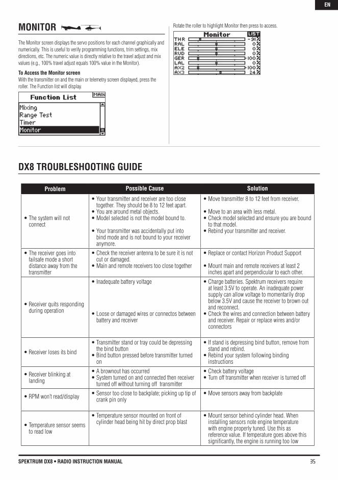
35SPEKTRUM DX8 • RADIO INSTRUCTION MANUAL
MONITOR The Monitor screen displays the servo positions for each channel graphically and numerically. This is useful to verify programming functions, trim settings, mix directions, etc. The numeric value is directly relative to the travel adjust and mix values (e.g., 100% travel adjust equals 100% value in the Monitor).
To Access the Monitor screenWith the transmitter on and the main or telemetry screen displayed, press the roller. The Function list will display.
Rotate the roller to highlight Monitor then press to access.
Problem Possible Cause Solution
•Thesystemwillnotconnect
•Yourtransmitterandreceiveraretooclosetogether. They should be 8 to 12 feet apart.
•Youarearoundmetalobjects.•Modelselectedisnotthemodelboundto.
•Yourtransmitterwasaccidentallyputintobind mode and is not bound to your receiver anymore.
•Movetransmitter8to12feetfromreceiver.
•Movetoanareawithlessmetal.•Checkmodelselectedandensureyouarebound
to that model.•Rebindyourtransmitterandreceiver.
•Thereceivergoesintofailsafe mode a short distance away from the transmitter
•Checkthereceiverantennatobesureitisnotcut or damaged.
•Mainandremotereceiverstooclosetogether
•ReplaceorcontactHorizonProductSupport
•Mountmainandremotereceiversatleast2inches apart and perpendicular to each other.
•Receiverquitsrespondingduring operation
•Inadequatebatteryvoltage
•Looseordamagedwiresorconnectosbetweenbattery and receiver
•Chargebatteries.Spektrumreceiversrequireat least 3.5V to operate. An inadequate power supply can allow voltage to momentarily drop below 3.5V and cause the receiver to brown out and reconnect.
•Checkthewiresandconnectionbetweenbatteryand receiver. Repair or replace wires and/or connectors
•Receiverlosesitsbind
•Transmitterstandortraycouldbedepressingthe bind button
•Bindbuttonpressedbeforetransmitterturnedon
•Ifstandisdepressingbindbutton,removefromstand and rebind.
•Rebindyoursystemfollowingbindinginstructions
•Receiverblinkingatlanding
•Abrownouthasoccurred•Systemturnedonandconnectedthenreceiver
turned off without turning off transmitter
•Checkbatteryvoltage•Turnofftransmitterwhenreceiveristurnedoff
•RPMwon’tread/display •Sensortooclosetobackplate;pickinguptipofcrank pin only
•Movesensorsawayfrombackplate
•Temperaturesensorseemsto read low
•Temperaturesensormountedonfrontofcylinder head being hit by direct prop blast
•Mountsensorbehindcylinderhead.Wheninstalling sensors note engine temperature with engine properly tuned. Use this as reference value. If temperature goes above this significantly, the engine is running too low
DX8 TROUbLEShOOTING GUIDE
EN
36 SPEKTRUM DX8 • RADIO INSTRUCTION MANUAL
GENERAL INFORMATION
Servo Precautions•Donotlubricateservogearsormotors.•Donotoverloadretractservosduringretractedorextendedconditions.Makesure they are able to travel their full deflection. Overloading or stalling a servo can cause excessive current drain.•Makesureallservosmovefreelythroughtheirrotationsandnolinkageshang up or bind. A binding control linkage can cause a servo to draw excessive current. A stalled servo can drain a battery pack in a matter of minutes.•Correctanycontrolsurface“buzz”or“flutter”assoonasitisnoticedinflight,as this conditioncan destroy the feedback potentiometer in the servo. It may be extremely dangerous to ignore such “buzz” or “flutter.”•Usethesuppliedrubbergrommetsandbrassservoeyeletswhenmountingyour servos. Do not over-tighten the servo mounting screws, as this negates the dampening effect of the rubber grommets.•Ensuretheservohornissecurelyfastenedtotheservo.Useonlytheservoarmscrews provided; the size is different from other manufacturers.•Discontinuetouseservoarmswhentheybecome“yellowed”ordiscolored.Such servo arms may be brittle and can snap at any time, possibly causing the aircraft to crash.•Checkallrelatedmountingscrewsandlinkagesfrequently.Aircraftoftenvibrate, causing linkages and screws to loosen.
General NotesRadio controlled models are a great source of pleasure. Unfortunately, they can also pose a potential hazard if not operated and maintained properly.It is imperative to install your radio control system correctly. Additionally, your level of piloting competency must be high enough to ensure that you are able to control your aircraft under all conditions. If you are a newcomer to radio controlled flying, please seek help from an experienced pilot or your local hobby store.
Safety, Precautions, and WarningsAs the user of this product, you are solely responsible for operating it in a manner that does not endanger yourself and others or result in damage to the product or the property of others.Carefully follow the directions and warnings for this and any optional support equipment (chargers, rechargeable battery packs, etc.) that you use.This model is controlled by a radio signal that is subject to interference from many sources outside your control. This interference can cause momentary loss of control so it is necessary to always keep a safe distance in all directions around your model, as this margin will help to avoid collisions or injury.•Alwaysoperateyourmodelinanopenareaawayfromcars,traffic,orpeople.•Avoidoperatingyourmodelinthestreetwhereinjuryordamagecanoccur.•Neveroperatethemodeloutintothestreetorpopulatedareasforanyreason.•Neveroperateyourmodelwithlowtransmitterbatteries.•Carefullyfollowthedirectionsandwarningsforthisandanyoptionalsupportequipment (chargers, rechargeable battery packs, etc.) that you use.•Keepallchemicals,smallpartsandanythingelectricaloutofthereachofchildren.•Moisturecausesdamagetoelectronics.Avoidwaterexposuretoallequipmentnot specifically designed and protected for this purpose.
Do not operate more than 40 DSM transmitters simultaneously.
Safety Do’s and Don’ts for Pilots•Ensurethatyourbatterieshavebeenproperlychargedpriortoyourinitialflight.•Keeptrackofthetimethesystemisturnedonsoyouwillknowhowlongyoucan safely operateyour system.
•Performagroundrangecheckpriortotheinitialflightoftheday.Seethe“DailyFlight Checks Section” for information.•Checkallcontrolsurfacespriortoeachtakeoff.•Donotflyyourmodelnearspectators,parkingareasoranyotherareathatcould result in injury to people or damage of property.•Donotflyduringadverseweatherconditions.Poorvisibilitycancausedisorientation and loss of control of your aircraft. Strong winds can cause similar problems.•Donotpointthetransmitterantennadirectlytowardthemodel.Theradiationpattern from the tip of the antenna is inherently low.•Donottakechances.Ifatanytimeduringflightyouobserveanyerraticorabnormal operation, land immediately and do not resume flight until the cause of the problem has been ascertained and corrected. Safety can never be taken lightly.
Federal Aviation AdministrationpurposeThis advisory outlines safety standards for operations of model aircraft. We encourage voluntary compliance with these standards.
backgroundAttention has been drawn to the increase in model aircraft operation. There is a need for added caution when operating free flight and radio controlled craft in order to avoid creating a noise nuisance or a potential hazard to full-scale aircraft and persons and/or property on the surface.
Operating StandardsModelers generally are concerned with safety and exercise good judgment when flying model aircraft. However, in the interest of safer skies, we encourage operators of radio controlled and free flight models to comply with the following standards:a. Exercise vigilance in locating full-scale aircraft (get help if possible) so as not to create a collision hazard.b. Select an operating site at sufficient distance from populated areas so you do not create a noise problem or a potential hazard.c. Do not fly higher than 400 feet above the surface.d. Always operate more than three miles from the boundary of an airport unless you are given permission to be closer by the appropriate air traffic control facility in the case of an airport for which a control zone has been designated or by the airport manager in the case of other airports.e. Do not hesitate to ask for assistance in complying with these guidelines at the airport traffic control tower or air route traffic control center nearest the site of your proposed operation.
Information Provided byDirector, Air Traffic Service Federal Aviation Administration, Washington, D.C.Daily Flight Checks1. Check the battery voltage on both the transmitter and the receiver battery packs. Do not fly below 4.3V on the transmitter or below 9V on the receiver. To do so can crash your aircraft.Note: When you check these batteries, ensure that you have the polarities correct on your expanded scale voltmeter.2. Check all hardware (linkages, screws, nuts, and bolts) prior to each day’s flight. Be sure that binding does not occur and that all parts are properly secured.3. Ensure that all surfaces are moving in the proper manner.4. Perform a ground range check before each day’s flying session.5. Prior to starting your aircraft, turn off your transmitter, then turn it back on. Do this each time you start your aircraft. If any critical switches are on without your knowledge, the transmitter alarm will warn you at this time.6. Check that all trim levers are in the proper location.7. All servo pigtails and switch harness plugs should be secured in the receiver. Make sure that the switch harness moves freely in both directions.
EN
37SPEKTRUM DX8 • RADIO INSTRUCTION MANUAL
WARRANTy AND RePAIR PoLICyWarranty period
Exclusive Warranty- Horizon Hobby, Inc., (Horizon) warranties that the Products purchased (the “Product”) will be free from defects in materials and workmanship for 1 year from the date of purchase by the Purchaser.
1-Year Limited Warranty
horizon reserves the right to change or modify this warranty without notice and disclaims all other warranties, express or implied.
(a) This warranty is limited to the original Purchaser (“Purchaser”) and is not transferable. REPAIR OR REPLACEMENT AS PROVIDED UNDER THIS WARRANTY IS THE EXCLUSIVE REMEDY OF THE PURCHASER. This warranty covers only those Products purchased from an authorized Horizon dealer. Third party transactions are not covered by this warranty. Proof of purchase is required for all warranty claims.
(b) Limitations- HORIZON MAKES NO WARRANTY OR REPRESENTATION, EXPRESS OR IMPLIED, ABOUT NON-INFRINGEMENT, MERCHANTABILITY OR FITNESS FOR A PARTICULAR PURPOSE OF THE PRODUCT. THE PURCHASER ACKNOWLEDGES THAT THEY ALONE HAVE DETERMINED THAT THE PRODUCT WILL SUITABLY MEET THE REQUIREMENTS OF THE PURCHASER’S INTENDED USE.
(c) Purchaser Remedy- Horizon’s sole obligation hereunder shall be that Horizon will, at its option, (i) repair or (ii) replace, any Product determined by Horizon to be defective. In the event of a defect, these are the Purchaser’s exclusive remedies. Horizon reserves the right to inspect any and all equipment involved in a warranty claim. Repair or replacement decisions are at the sole discretion of Horizon. This warranty does not cover cosmetic damage or damage due to acts of God, accident, misuse, abuse, negligence, commercial use, or modification of or to any part of the Product. This warranty does not cover damage due to improper installation, operation, maintenance, or attempted repair by anyone other than Horizon. Return of any Product by Purchaser must be approved in writing by Horizon before shipment.
Damage Limits
HORIZON SHALL NOT BE LIABLE FOR SPECIAL, INDIRECT OR CONSEQUENTIAL DAMAGES, LOSS OF PROFITS OR PRODUCTION OR COMMERCIAL LOSS IN ANY WAY CONNECTED WITH THE PRODUCT, WHETHER SUCH CLAIM IS BASED IN CONTRACT, WARRANTY, NEGLIGENCE, OR STRICT LIABILITY. Further, in no event shall the liability of Horizon exceed the individual price of the Product on which liability is asserted. As Horizon has no control over use, setup, final assembly, modification or misuse, no liability shall be assumed nor accepted for any resulting damage or injury. By the act of use, setup or assembly, the user accepts all resulting liability.
If you as the Purchaser or user are not prepared to accept the liability associated with the use of this Product, you are advised to return this Product immediately in new and unused condition to the place of purchase.
Law: These Terms are governed by Illinois law (without regard to conflict of law principals).
WARRANTy SeRVICeSQuestions, Assistance, and Repairs
Your local hobby store and/or place of purchase cannot provide warranty support or repair. Once assembly, setup or use of the Product has been started, you must contact Horizon directly. This will enable Horizon to better answer your questions and service you in the event that you may need any assistance. For questions or assistance, please direct your email to [email protected], or call 877.504.0233 toll free to speak to a Product Support representative. You may also find information on our website at www.horizonhobby.com.
Inspection or Repairs
If this Product needs to be inspected or repaired, please use the Horizon Online Repair Request submission process found on our website or call Horizon to obtain a Return Merchandise Authorization (RMA) number. Pack the Product securely using a shipping carton. Please note that original boxes may be included, but are not designed to withstand the rigors of shipping without additional protection. Ship via a carrier that provides tracking and insurance for lost or damaged parcels, as Horizon is not responsible for merchandise until it arrives and is accepted at
EN
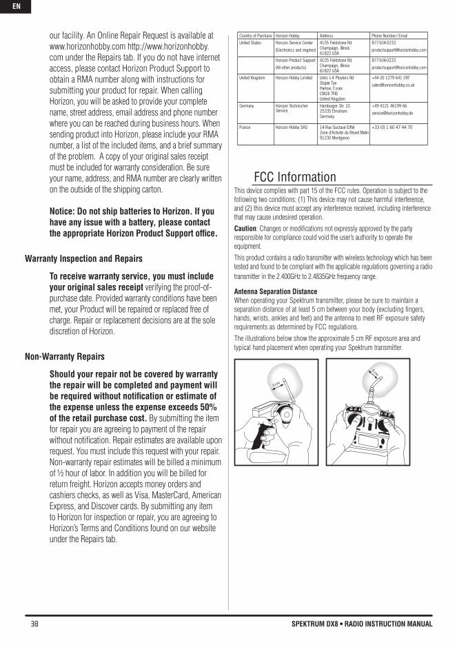
38 SPEKTRUM DX8 • RADIO INSTRUCTION MANUAL
our facility. An Online Repair Request is available at www.horizonhobby.com http://www.horizonhobby.com under the Repairs tab. If you do not have internet access, please contact Horizon Product Support to obtain a RMA number along with instructions for submitting your product for repair. When calling Horizon, you will be asked to provide your complete name, street address, email address and phone number where you can be reached during business hours. When sending product into Horizon, please include your RMA number, a list of the included items, and a brief summary of the problem. A copy of your original sales receipt must be included for warranty consideration. Be sure your name, address, and RMA number are clearly written on the outside of the shipping carton.
Notice: Do not ship batteries to horizon. If you have any issue with a battery, please contact the appropriate horizon Product Support office.
Warranty Inspection and Repairs
To receive warranty service, you must include your original sales receipt verifying the proof-of-purchase date. Provided warranty conditions have been met, your Product will be repaired or replaced free of charge. Repair or replacement decisions are at the sole discretion of Horizon.
Non-Warranty Repairs
Should your repair not be covered by warranty the repair will be completed and payment will be required without notification or estimate of the expense unless the expense exceeds 50% of the retail purchase cost. By submitting the item for repair you are agreeing to payment of the repair without notification. Repair estimates are available upon request. You must include this request with your repair. Non-warranty repair estimates will be billed a minimum of ½ hour of labor. In addition you will be billed for return freight. Horizon accepts money orders and cashiers checks, as well as Visa, MasterCard, American Express, and Discover cards. By submitting any item to Horizon for inspection or repair, you are agreeing to Horizon’s Terms and Conditions found on our website under the Repairs tab.
FCC InformationThis device complies with part 15 of the FCC rules. Operation is subject to the following two conditions: (1) This device may not cause harmful interference, and (2) this device must accept any interference received, including interference that may cause undesired operation.
Caution: Changes or modifications not expressly approved by the party responsible for compliance could void the user’s authority to operate the equipment.
This product contains a radio transmitter with wireless technology which has been tested and found to be compliant with the applicable regulations governing a radio transmitter in the 2.400GHz to 2.4835GHz frequency range.
Antenna Separation DistanceWhen operating your Spektrum transmitter, please be sure to maintain a separation distance of at least 5 cm between your body (excluding fingers, hands, wrists, ankles and feet) and the antenna to meet RF exposure safety requirements as determined by FCC regulations.
The illustrations below show the approximate 5 cm RF exposure area and typical hand placement when operating your Spektrum transmitter.
Country of Purchase Horizon Hobby Address Phone Number/ EmailUnited States Horizon Service Center
(Electronics and engines)
4105 Fieldstone RdChampaign, Illinois61822 USA
877-504-0233
Horizon Product Support
(All other products)
4105 Fieldstone RdChampaign, Illinois61822 USA
877-504-0233
United Kingdom Horizon Hobby Limited Units 1-4 Ployters RdStaple TyeHarlow, EssexCM18 7NSUnited Kingdom
+44 (0) 1279 641 097
Germany Horizon Technischer Service
Hamburger Str. 1025335 ElmshornGermany
+49 4121 46199 66
France Horizon Hobby SAS 14 Rue Gustave EiffelZone d’Activité du Réveil Matin91230 Montgeron
+33 (0) 1 60 47 44 70
EN
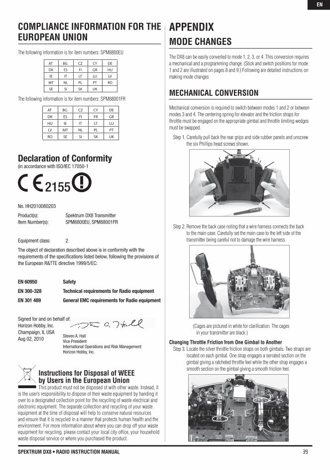
39SPEKTRUM DX8 • RADIO INSTRUCTION MANUAL
COMPLIANCE INFORMATION FOR ThE EUROPEAN UNIONThe following information is for item numbers: SPM8800EU
The following information is for item numbers: SPM88001FR
Declaration of Conformity(in accordance with ISO/IEC 17050-1
No. HH2010080203
Product(s): Spektrum DX8 TransmitterItem Number(s): SPM8800EU, SPM88001FR
Equipment class: 2
The object of declaration described above is in conformity with the requirements of the specifications listed below, following the provisions of the European R&TTE directive 1999/5/EC:
EN 60950 Safety
EN 300-328 Technical requirements for Radio equipment
EN 301 489 General EMC requirements for Radio equipment
Signed for and on behalf of:Horizon Hobby, Inc.Champaign, IL USAAug 02, 2010
Instructions for Disposal of WEEE by Users in the European UnionThis product must not be disposed of with other waste. Instead, it
is the user’s responsibility to dispose of their waste equipment by handing it over to a designated collection point for the recycling of waste electrical and electronic equipment. The separate collection and recycling of your waste equipment at the time of disposal will help to conserve natural resources and ensure that it is recycled in a manner that protects human health and the environment. For more information about where you can drop off your waste equipment for recycling, please contact your local city office, your household waste disposal service or where you purchased the product.
APPENDIXMODE ChANGESThe DX8 can be easily converted to mode 1, 2, 3, or 4. This conversion requires a mechanical and a programming change. (Stick and switch positions for mode 1 and 2 are illustrated on pages 8 and 9.) Following are detailed instructions on making mode changes
MEChANICAL CONvERSION
Mechanical conversion is required to switch between modes 1 and 2 or between modes 3 and 4. The centering spring for elevator and the friction straps for throttle must be engaged on the appropriate gimbal and throttle limiting wedges must be swapped.
Step 1. Carefully pull back the rear grips and side rubber panels and unscrew the six Phillips head screws shown.
Step 2. Remove the back case noting that a wire harness connects the back to the main case. Carefully set the main case to the left side of the transmitter being careful not to damage the wire harness.
(Cages are pictured in white for clarification. The cages in your transmitter are black.)
Changing Throttle Friction from One Gimbal to AnotherStep 3. Locate the silver throttle friction straps on both gimbals. Two straps are
located on each gimbal. One strap engages a serrated section on the gimbal giving a ratcheted throttle feel while the other strap engages a smooth section on the gimbal giving a smooth friction feel.
AT BG CZ CY DE
DK ES FI GR HU
IE IT LT LU LV
MT NL PL PT RO
SE SI SK UK
AT BG CZ CY DE
DK ES FI FR GR
HU IE IT LT LU
LV MT NL PL PT
RO SE SI SK UK
Steven A. Hall Vice PresidentInternational Operations and Risk ManagementHorizon Hobby, Inc.
2155
EN
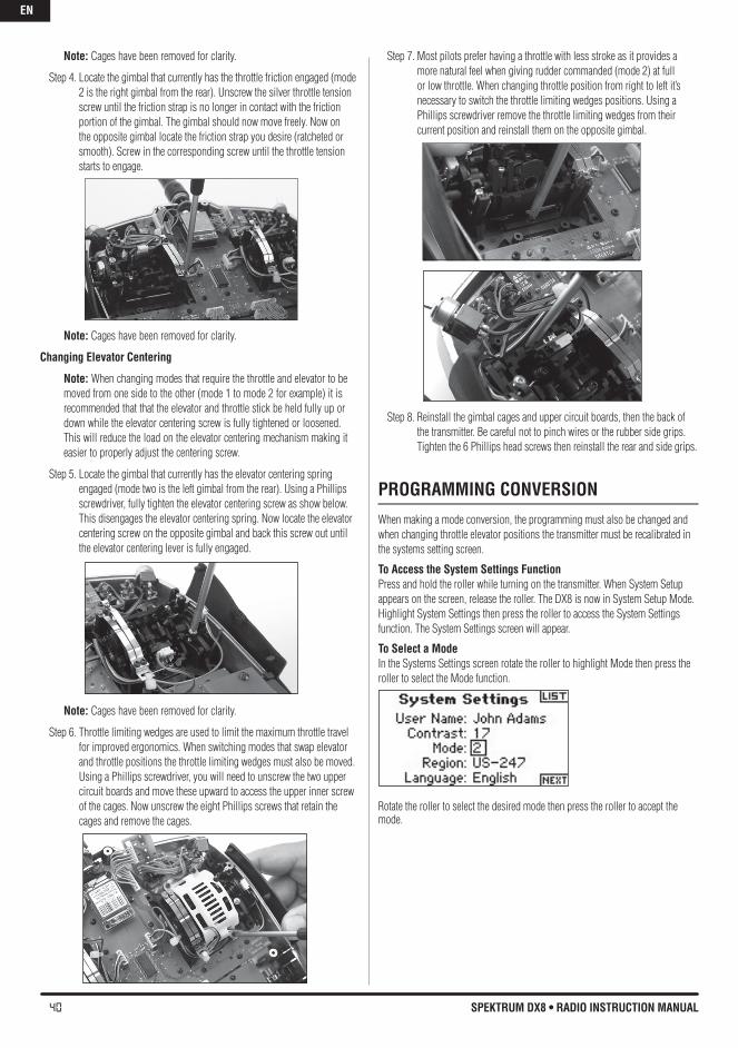
40 SPEKTRUM DX8 • RADIO INSTRUCTION MANUAL
Note: Cages have been removed for clarity.
Step 4. Locate the gimbal that currently has the throttle friction engaged (mode 2 is the right gimbal from the rear). Unscrew the silver throttle tension screw until the friction strap is no longer in contact with the friction portion of the gimbal. The gimbal should now move freely. Now on the opposite gimbal locate the friction strap you desire (ratcheted or smooth). Screw in the corresponding screw until the throttle tension starts to engage.
Note: Cages have been removed for clarity.
Changing Elevator Centering
Note: When changing modes that require the throttle and elevator to be moved from one side to the other (mode 1 to mode 2 for example) it is recommended that that the elevator and throttle stick be held fully up or down while the elevator centering screw is fully tightened or loosened. This will reduce the load on the elevator centering mechanism making it easier to properly adjust the centering screw.
Step 5. Locate the gimbal that currently has the elevator centering spring engaged (mode two is the left gimbal from the rear). Using a Phillips screwdriver, fully tighten the elevator centering screw as show below. This disengages the elevator centering spring. Now locate the elevator centering screw on the opposite gimbal and back this screw out until the elevator centering lever is fully engaged.
Note: Cages have been removed for clarity.
Step 6. Throttle limiting wedges are used to limit the maximum throttle travel for improved ergonomics. When switching modes that swap elevator and throttle positions the throttle limiting wedges must also be moved. Using a Phillips screwdriver, you will need to unscrew the two upper circuit boards and move these upward to access the upper inner screw of the cages. Now unscrew the eight Phillips screws that retain the cages and remove the cages.
Step 7. Most pilots prefer having a throttle with less stroke as it provides a more natural feel when giving rudder commanded (mode 2) at full or low throttle. When changing throttle position from right to left it’s necessary to switch the throttle limiting wedges positions. Using a Phillips screwdriver remove the throttle limiting wedges from their current position and reinstall them on the opposite gimbal.
Step 8. Reinstall the gimbal cages and upper circuit boards, then the back of the transmitter. Be careful not to pinch wires or the rubber side grips. Tighten the 6 Phillips head screws then reinstall the rear and side grips.
PROGRAMMING CONvERSION
When making a mode conversion, the programming must also be changed and when changing throttle elevator positions the transmitter must be recalibrated in the systems setting screen.
To Access the System Settings FunctionPress and hold the roller while turning on the transmitter. When System Setup appears on the screen, release the roller. The DX8 is now in System Setup Mode.Highlight System Settings then press the roller to access the System Settings function. The System Settings screen will appear.
To Select a ModeIn the Systems Settings screen rotate the roller to highlight Mode then press the roller to select the Mode function.
Rotate the roller to select the desired mode then press the roller to accept the mode.
EN
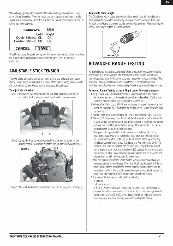
41SPEKTRUM DX8 • RADIO INSTRUCTION MANUAL
When changing modes that swap throttle and elevator positions it’s necessary to recalibrate the sticks. When the mode change is programmed, the calibration screen will automatically appear the next time the transmitter is turned on and the following screen appears.
To calibrate, move the sticks throughout their range then back to center including the throttle. Once all sticks have been centered, press SAVE to complete calibration.
ADjUSTAbLE STICK TENSION
The DX8 offers adjustable tension on the throttle, aileron, elevator and rudder sticks. Rubber plugs are installed in the back of the case allowing easy access to the stick tension screws without having to remove the back case.
To adjust stick tension: Step 1. Remove the two rubber plugs and pull back the grips as shown to
access the throttle, aileron, elevator and rudder tension screws.
Step 2. Using a Phillips screwdriver, adjust the stick tension screw for the desired control. Clockwise to tighten and counterclockwise to loosen.
Step 3. When satisfied with the stick tension, reinstall the grips and rubber plugs.
Adjustable Stick LengthThe DX8 allows you to adjust the control stick’s length. Use the included 2mm Allen wrench to loosen the setscrew by turning it counterclockwise. Then, turn the stick clockwise to shorten or counterclockwise to lengthen. After adjusting the control stick length tighten the 2mm setscrew.
ADvANCED RANGE TESTINGFor sophisticated aircraft that contain significant amounts of conductive/reflective materials (e.g., turbine-powered jets, some types of scale aircraft, aircraft with carbon fuselages, etc.), the following advanced range check is recommended. This Advanced Range Check allows you to evaluate the RF performance of eachindividual internal and remote receiver and optimize the locations of these receivers.
Advanced Range Testing Using a Flight Log or Telemetry Module1. Plug a flight log or the telemetry module (optional) into the data port in
the receiver and turn on the system (transmitter and receiver). If using the Telemetry module, make sure it’s bound to the receiver.
2. Advance the Flight Log until F- frame losses are displayed, by pressing the button on the flight log. Or advance the screen on the DX8 to show the flight log telemetry.
3. Have a helper hold your aircraft while he/she observes the Flight Log data.4. Standing 30 paces away from the model, face the model with the transmitter
in your normal flying Position. Place the transmitter in the range test screen and push and hold the trainer button on top of the transmitter. This causes reduced power output from the transmitter.
5. Have your helper position the model in various orientations (nose up, nose down, nose toward the transmitter, nose away from the transmitter, etc.) while watching the Flight Log, or the on screen telemetry noting any correlation between the aircraft’s orientation and Frame Losses. Do this for 1 minute. The timer on the DX8 can be used here. For giant-scale aircraft, tip the airplane up on its nose and rotate it 360 degrees for one minute, then record the data. Next, place the airplane on its wheels and do a second test, rotating the aircraft in all directions for one minute.
6. After one minute, release the trainer switch. A successful range check will have recorded zero frame losses. Scroll the Flight Log through the Antenna fades to evaluate the performance of each receiver. Antenna fades should be relatively uniform. If a specific antenna is experiencing a high degree of fades, then that antenna should be moved to a different location.
7. A successful Advanced test will yield the following: H- 0 holds F- 0 frame losses A, B, R, L- Antenna fades will typically be less than 100. It’s important to compare the relative antenna fades. If a particular receiver has significantly higher antenna fades (2 to 3X), then the test should be redone. If the same results occur, move the offending receiver to a different location.
Aileron
Elevator
Mode 2
Rudder
Throttle
EN
42 SPEKTRUM DX8 • RADIO INSTRUCTION MANUAL
USING A FLIGhT LOG—OPTIONALThe Flight Log (optional) is compatible with the AR8000 receiver. The Flight Log displays overall RF link performance as well as the individual internal and external receiver link data. It also displays receiver voltage.
Using the Flight LogAfter a flight and before turning off the receiver or transmitter, plug the Flight Log into the Data port on the AR8000 receiver. The screen will automatically display voltage i.e. 6v2= 6.2 volts. Note: When the voltage reaches 4.8 volts or less, the screen will flash indicating low voltage.Press the button to display the following information:
A - Antenna fades on internal antenna AB - Antenna fades on internal antenna B (not used on the AR8000)L - Antenna fades on the left external antennaR - Antenna fades on the right external antenna (not used on the AR8000)F - Frame lossH - Holds
Antenna fades—represents the loss of a bit of information on that specific antenna. It’s normal to have as many as 50 to 100 antenna fades during a flight. If any single antenna experiences over 500 fades in a single flight, the antenna should be repositioned in the aircraft to optimize the RF link.
Frame loss—represents simultaneous antenna fades on all attached receivers. If the RF link is performing optimally, frame losses per flight should be less than 20.
A hold- occurs when 45 continuous frame losses occur. This takes about one second. If a hold occurs during a flight, it’s important to re-evaluate the system, moving the antennas to different locations and/or checking to be sure the transmitter and receivers are all working correctly.
Note: Use a servo extension to allow the Flight Log to be plugged in without having to remove the aircraft’s hatch or canopy. On some models, the Flight Log can be plugged in, attached and left on the model using double-sided tape. It is common with helicopters to mount the Flight Log to the side frame.
EN