Embed Size (px)
Citation preview
PLEASE READ THIS MANUAL CAREFULLY BEFORE OPERATION
3, Hagavish st. Israel 58817 Tel: 972 3 5595252, Fax: 972 3 5594529 [email protected]
MRC.VER.02-11.10
INSTRUCTION MANUAL FOR
SPECTRO- UV61/UV63 UV/VIS SPECTROPHOTOMETERS

I
Contents
Preface…………………………………………………………………………………………………………………………………………………………………………………………………………………………………………………………………………………………………………………………………………………………………………1
1. Safety……………………………………………………………………………………1
2. About the Instrument………………………………………………………………….1
3. Symbols… ………………………………………………………………………………1
Chapter I Preface.............................................................................................2
1. Working principle and structure......................................................................2
2. Main Specifications………………………………………………………………………2
3. Main Functions.............................................................................................3
Chapter II Install Instrument……………………………………………………………………………………………………………………………………………………………………………………………………………………………………………………4
1. Environment Required…………………………………………………………………4
2. Voltage Confirmation…………………………………………………………………4
3. Installation………………………………………………………………………………4
Chapter III Introduction of the Instrument……………………………………………………………………………………………………………………………………………………………………………………6
1. Introduction of the instrument……………………………………………………… 6
2. Operation Panel………………………………………………………………………… 7
3. Keypad Description…………………………………………………………………… 7
Chapter IV Operation Introduction………………………………………………………………………………………………………………………………………………………………………………………………………………………………9
1. Software Structure……………………………………………………………………… 9
2. Basic Operation…………………………………………………………………………10
1) Choose Photometric Mode………………………………………………………10
2) Set Wavelength………………………………………………………………10
3) Set Parameters…………………………………………………………………10
4) Set the position of auto-cell holder……………………………………………10
5) Delete the Input Value…………………………………………………………10
6) Delete the test result and stored data………………………………………10
7) Calibrate 100%T/0Abs…………………………………………………………10
8) Measure Samples………………………………………………………………11
9) Print the test result……………………………………………………………11
10) Save Test Result…………………………………………………………………………………11
11) Load Saved Data…………………………………………………………………11
3. Preparation before test………………………………………………………………11
1) Switch on the instrument and begin the system self-test……………………11
2) Pre-warm………………………………………………………………………11
3) Check the cuvettes……………………………………………………………11
4. Measurement……………………………………………………………………………12
1) Basic Mode………………………………………………………………………12
II
2) Quantitative Mode………………………………………………………………13
3) Wavelength Scan………………………………………………………………18
4) Kinetics Mode……………………………………………………………………………………20
5) DNA/Protein Mode…………………………………………………………………………….22
6) Multi-wavelength Mode………………………………………………………………………24
5. System Utility……………………………………………………………………………………………..25
1) Wavelength Reset……………………………………………………………………………..26
2) Printer Setup…………………………………………………………………………………….26
3) Lamp Service.......................................................................................27
4) Clock Setup………………………………………………………………………………………29
5) Refresh Dark Current…………………………………………………………………………30
6) Connect to PC…………………………………………………………………………………..30
7) Beeper On/Off…………………………………………………………………………………..31
8) Language Selection……………………………………………………………………………31
9) Refresh System Baseline…………………………………………………………………….31
10) Delete Entire Saved Files……………………………………………………………………31
11) Restore Default Settings…………………………………………………………………….31
12) Slot Setup………………………………………………………………………………………….32
Chapter V Instrument Maintenance……………………………………………………………………………………………………………………………………………………………………………………………………………………33
1. Daily Maintain……………………………………………………………………………33
1) Check the compartment…………………………………………………………33
2) Surface Clean……………………………………………………………………33
3) Clean the Cuvettes………………………………………………………………33
2. Trouble Shooting………………………………………………………………………33
1) Self-test Error……………………………………………………………………33
2) No Response when power on…………………………………………………33
3) Printer not work, printer error…………………………………………………33
4) No stable readings………………………………………………………………33
5) Worse Repeatability……………………………………………………………34
6) Incorrect readings………………………………………………………………34
3. Spare parts replacement………………………………………………………………34
1) Replace Fuse……………………………………………………………………34
2) Replace Lamps…………………………………………………………………35
3) Replace Battery…………………………………………………………………38
- 1 -
PREFACE
1. SAFETY
This instruments are designed according to the following safety documents:《IEC
61010 — 1:2001》(Which is:《Measurement, Control and Laboratory Electric Equipments
Safety Requirement》Part 1) and 《IEC 60601 — 1:1988》(Which is:《Electric Apparatus
of Medical Treatment》 Part 1).
2. About the Instruments
Series UV61/63 Spectrophotometer is an electrical test instruments which is widely used in the laboratories.
� Use Frequency: Intermittence
� Excessive Voltage (Current): No
� Pollution Class: Class 1
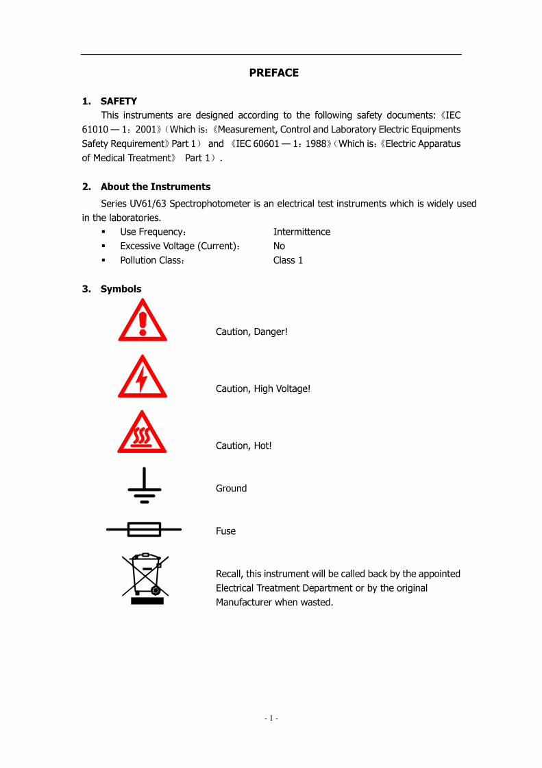
3. Symbols
Caution, Danger!
Caution, High Voltage!
Caution, Hot!
Ground
Fuse
Recall, this instrument will be called back by the appointed
Electrical Treatment Department or by the original
Manufacturer when wasted.

- 2 -
Chapter I Summary
Series UV61/63 Spectrophotometers have the characters of wide range of wavelength, high sensitivity, powerful function, easy to use, simple structure and pretty figure.
Besides these, the large LCD, High Precise A/D and easy to store RAM makes the
instrument much more superior than other originals. It is widely used in Chemistry,
Pharmaceuticals, Biochemical, metallurgy, Light Industry, Textile, Material,
Environments, Medical, Education and some other fields. It is one of the most
important instruments in Quality Control and an essential in normal laboratories.
1. Working Principle and Structure
Different matter has different but special absorbance wavelength point. Also, when at
the fixed wavelength point, the absorbance has some relation to the substance’s
(Always transparent Solution) concentration and its thickness. The relation can be
concluded as the following Formula which is called Lambert-Beer Law.
T= I/Io
A=KCL= -log I/Io
A Absorbance
C Concentration of the Solution
K Absorbance Coefficient of the Solution
L The length of the Solution in the light path
I The intensity of the light focused on the A\D after it permeate the solution to
be measured.
Io The intensity of the light focused on the A/D after it permeate the Solution.
Note: When test, the solvent is usually taken as the Reference Solution
and its Transmittance is considered as 100%T. While the
Transmittance of the sample to be tested is a relative value which
is got comparing to that of the Reference.
2. Main Specifications
� Optical System: Double Beam
� Wavelength Range: 190-1100nm
� Stray Light: ≤0.05%T @ 220nm & 360nm
� Band Width: 1nm(UV63),1.8nm(UV61),
0.5, 1.0, 2.0, 4.0nm(UV61PC) � Photometric Range: 0-200%T,-0.3-3.0A
� Wavelength Accuracy: ±0.3nm
� WL. Repeatability: ≤0.2nm
� Photometric Accuracy: ±0.2nm
� Stability: 0.001A/h @ 500nm

- 3 -
� Display: 320×240 Dots Matrix LCD
� Data Output: USB,Parallel Port
� Dimension: 590×420×260
� Weight: 26kg
3. Main Functions
Series UV61/63 have 7 functions. � Photometry
This is the basic mode, the photometric mode can be switched between
Absorbance and Transmittance. You can use 2-points method to measure the
concentration.
� Quantitative
Two methods are included in the menu: Coefficient Method and Standard
Curve Method. The Regression Equation and the test result can be stored in the
RAM and printed out.
� Wavelength Scan
Scan Range and scan intervals can be set(0.1nm, 0.2nm, 0.5nm, 1.0nm,
2.0nm, 5.0nm),the data and Curve and be stored and printed out.
� Kinetics
The minimum sampling interval is 0.5 second, the data and curve can be
stored and printed out.
� DNA/Protein Test
Provide two methods. Customers can also set the parameters. The data can
be printed out.
� Multi-wavelength Test
Users can set several wavelengths before test, then the system will test all
the T or A values of the setting wavelength one by one. The result can be printed
out.
� Utility
Users can set the favorable items to keep the instrument work in best
conditions.

- 4 -
Chapter II Install Instrument
1. Environment Required
To ensure the best performance, the following conditions are required:
� The best working temperature range is 16-35℃ and the humidity is 45-80%.
� Keep it as far as possible away from the strong magnetic or electrical fields or any
electrical device that may generate high-frequency fields.
� Set the unit up in an area that is free of dust, corrosive gases and strong
vibrations.
� Remove any obstructions or materials that could hinder the flow of air under and
around the instrument.
� The power requirement is 220±22V@50±1Hz or 110±11V@60±1 Hz.
� Use the appropriate power cord and plug into a grounded outlet.
� If the local voltage is not stable enough, a manostat is required.
� Be away from direct sunlight
2. Voltage Confirmation
Be sure to set the instrument’s voltage switch at your local power
supply, or severe damage may occur!
3. Installation
Step 1: Check the packing list
Unpack the contents, check the materials with the Packing List. Any damage or
Lost found, please contact us or the local dealer.
Step 2: Position
Place the instrument on the stable table carefully.
Step 3: Install printer (Optional)
Make sure the printer is power off; link the printer’s data cable to the Instrument’s
parallel port.
Step 4: Link the power cord
Make sure the instrument’s power switch is in the Off condition, link the power
cord to the instrument and insert another end in the socket provided with a
protective earth contact.
Step 5: Switch on the power
Check again; make sure that all the links are right. Switch on the power. Then the
instrument begins to self-test. After self-test and 15 minutes’ pre-warm, it can
work. The self-test includes the following steps:
D2 Lamp Pre-warm → Com-port Initialization → Initialize Printer → Start kernel
→ Initialize AD → Filter position → pre-warm (Fig.2-2)
After pre-warm, the instrument will ask the user to re-calibrate the system. (Fig.

- 5 -
2-3) Users can decide if they need to re-calibrate the system or not. After this
step, the instrument can work normally. (Fig.2-4)
After transportation or a period of use, the working condition
of the instrument may changed because of the changing of
the environment or other cause(The attenuation of the lights’
energy, Vibration),,,, then users need to re-calibrate the
system to keep it in the best working condition.
Fig. 2-1
Fig. 2-2
Fig. 2-3
Fig. 2-4

- 6 -
Chapter III Introduction of the Instrument
1. Introduction
Appearance of the instrument (Fig. 3-1):
Fig. 3-1
1 — Lid of the compartment
2 — Cell Holder
3 — Operation Panel
4 — Fan Cover
5 — Power Switch
6 — Power Socket
7 — Parallel Port
8 — USB Port
- 7 -
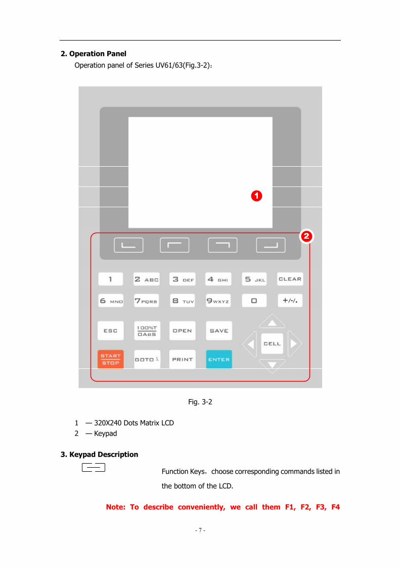
2. Operation Panel
Operation panel of Series UV61/63(Fig.3-2):
Fig. 3-2
1 — 320X240 Dots Matrix LCD
2 — Keypad
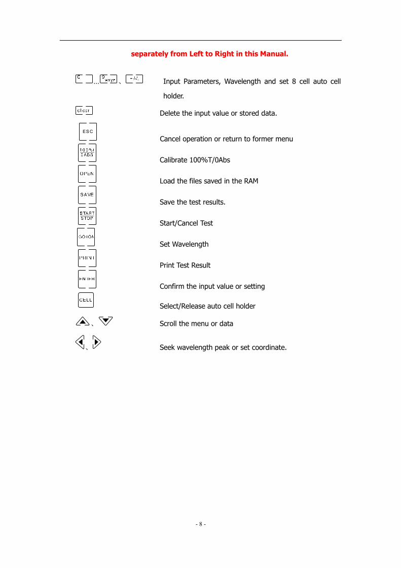
3. Keypad Description
Function Keys,choose corresponding commands listed in
the bottom of the LCD.
Note: To describe conveniently, we call them F1, F2, F3, F4
- 8 -
separately from Left to Right in this Manual.
… 、 Input Parameters, Wavelength and set 8 cell auto cell
holder.
Delete the input value or stored data.
ES C
Cancel operation or return to former menu
Calibrate 100%T/0Abs
Load the files saved in the RAM
Save the test results.
Start/Cancel Test
Set Wavelength
Print Test Result
Confirm the input value or setting
Select/Release auto cell holder
、 Scroll the menu or data
、 Seek wavelength peak or set coordinate.

- 9 -
Chapter IV Instrument Operation
1. Software Structure
Software structure of Series UV61/63(Fig. 4-1)
Main Menu Basic Mode
Quantitative
Wavelength
Scan
Set Unit
Photometric
Mode
Factor
Coefficient
Fitting Method
2-Points Method
Measure
Measure
Set Unit
Fitting Curve
Standard
Curve
Scan
Mode
Setting
Search
Smooth
Kinetics Measure
Mode
Setting
Curve Disposal
Search
DNA/Protein Measure
Choose method
Factor
Unit
Load default
Multi-
wavelengthMeasure
Set wavelength
Mode
Search 656.1nm
Light source
manage
Set printer
Clock manage
Calibrate dark
current
Baseline
Connect PC
Choose language
Beeper switch
Load Default
Initialize
Utility
Slit choose
Fig. 4-1
- 10 -
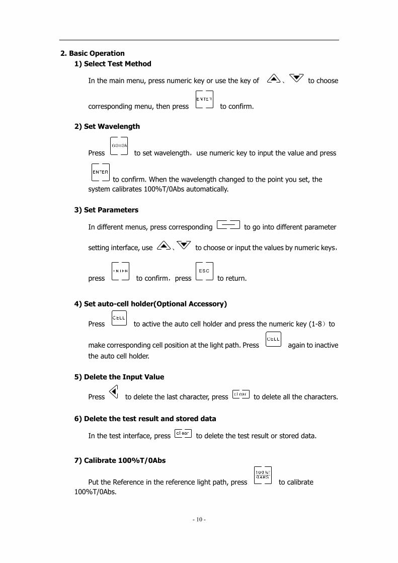
2. Basic Operation
1) Select Test Method
In the main menu, press numeric key or use the key of 、 to choose
corresponding menu, then press to confirm.
2) Set Wavelength
Press to set wavelength,use numeric key to input the value and press
to confirm. When the wavelength changed to the point you set, the
system calibrates 100%T/0Abs automatically.
3) Set Parameters
In different menus, press corresponding to go into different parameter
setting interface, use 、 to choose or input the values by numeric keys,
press to confirm,press ES C
to return.
4) Set auto-cell holder(Optional Accessory)
Press to active the auto cell holder and press the numeric key (1-8)to
make corresponding cell position at the light path. Press again to inactive
the auto cell holder.
5) Delete the Input Value
Press to delete the last character, press to delete all the characters.
6) Delete the test result and stored data
In the test interface, press to delete the test result or stored data.
7) Calibrate 100%T/0Abs
Put the Reference in the reference light path, press to calibrate
100%T/0Abs.

- 11 -
8) Measure Samples
In the test interface, put the samples to be tested in the light path, press
to measure.
9) Print the test result
In the test interface, press to print the test result.
10) Store the test result
In the test interface, press to store the test result, input the file name
by numeric keys and press to confirm.
11) Load the stored file
In the test interface, press to go into file selecting interface, press 、
to choose the file you want, press to open.
In different menu, users can only load the files with the
corresponding postfix. List is the corresponding postfixes:
� Quantitative:::: *.qua
� Standard Curve:::: *.fit
� Wavelength Scan:::: *.wav
� Kinetics:::: *.kin
� DNA/Protein test:::: *.dna
� Multi-wavelength:::: *.mul
3. Before Measurement
1) Self-test
Remove all the blocks in the light path and close the lid of the compartment;
Switch on the power supply to begin the self-test.
2) Pre-warm up
After self-test, the instrument goes into pre-warm state. For accurate test, at least
30 minutes of warm up is required.
3) Check the cuvettes
The cuvettes must be clear and there’s no remains of the samples on the surface
of it. Only Silicon (Quartz) cuvettes are permitted to be used in the range of UV area.

- 12 -
4. Measurement
1) Basic Mode
Step 1, Go into test interface of basic mode
In the main menu,press the key of or press 、 to choose
“Basic Mode” followed with pressed to go into the test interface
(Fig. 4-2);
Fig. 4-2
Step 2, Set Photometric Mode
Press F2 to set photometric mode. Press 、 to choose
“Abs.”、“T%” or “Conc/Factor” and press to confirm. If users choose
“Abs.” or “T%”, please go to step 5 directly.
Step 3 Set Concentration Unit
Press F1 to set concentration unit. Press 、 to choose
unit followed with pressed to confirm. You can also choose “other” to
input the self defined unit.
Step 4 Set “Factor” or “Standard”
Two methods are under your choice:
Method 1::::Input Factor F
Press F3 to set F. Input the value of F by numeric keypad,press
to confirm. Then the F value would display on the LCD.
Method 2::::Standards Mark
Put the Reference Sample in the light path and calibrate 100%T/0Abs; Put
the standard sample in the light path,press F4 to start the mark.

- 13 -
Input the concentration value of the standard and press to confirm,
then it displays on the screen.
Step 5 Set Wavelength
Press to set wavelength, input the value by the numeric keypad
followed with pressed to confirm
Step 6 Calibrate 100%T/0Abs
Put the Reference in the reference light path and press to calibrate
100%T/0Abs;
Step 7 Sample Measurement
Put the sample to be measured in the light path, then the result displays on
the screen automatically.
Step 8: Print Data
Press to print the result.
2) Quantitative
Step 1: Go into Quantitative Test Interface
In the main menu, press or press 、 to choose
“Quantitative Mode” followed with pressed to confirm(Fig.4-3);
Fig. 4-3
Step 2 Set Unit

- 14 -
Press F1 to set concentration unit, press 、 to choose
and press to confirm.
Step 3 Set up Standard Curve or load the stored curves
Press F2 to go into set up interface(Fig. 4-4),2 methods are under
your choice.
Fig. 4-4
Set up Standard Curve::::
Method 1::::Input Regression Equation
1) Set Fit Curve Method。。。。Press F1 to set Fit method,use
、 to choose the method and press to confirm.
2) Set Wavelength。。。。 Press to set wavelength. Use 、
to choose measure method, then press to confirm.
Input the wavelength value you need and press to
confirm.
3) Input the Factor of the Regression Equation。。。。 Press F2
and input the factors,press to confirm.
Method 2::::Use Standard Samples
- 15 -
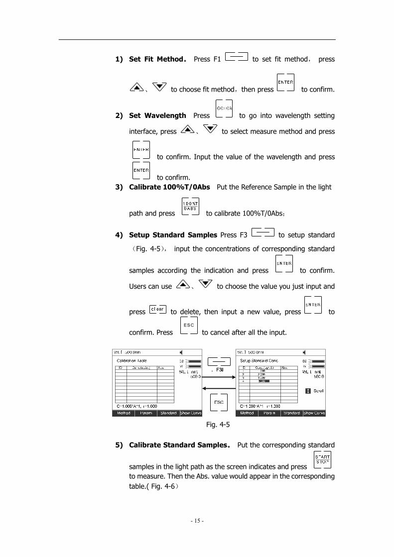
1) Set Fit Method。。。。 Press F1 to set fit method, press
、 to choose fit method,then press to confirm.
2) Set Wavelength Press to go into wavelength setting
interface, press 、 to select measure method and press
to confirm. Input the value of the wavelength and press
to confirm.
3) Calibrate 100%T/0Abs Put the Reference Sample in the light
path and press to calibrate 100%T/0Abs;
4) Setup Standard Samples Press F3 to setup standard
(Fig. 4-5), input the concentrations of corresponding standard
samples according the indication and press to confirm.
Users can use 、 to choose the value you just input and
press to delete, then input a new value, press to
confirm. Press ES C
to cancel after all the input.
Fig. 4-5
5) Calibrate Standard Samples。。。。 Put the corresponding standard
samples in the light path as the screen indicates and press
to measure. Then the Abs. value would appear in the corresponding
table.( Fig. 4-6)

- 16 -
Fig. 4-6
Load the Stored Curves::::
In the “Calibration Table” interface,press to go into files select
interface. Use 、 to select the curve you need and press
to load.
Users can press F4 to see the curve.(Fig. 4-7),press ES C
to cancel.
Fig. 4-7
Step 4: Return the sample measurement interface
In the “Calibration Table” interface,press ES C
to return the Quantitative
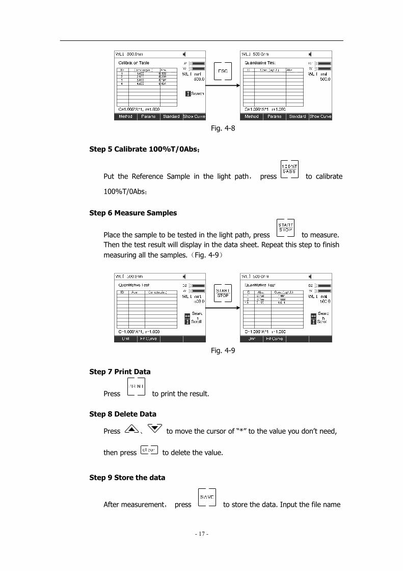
Test interface(Fig. 4-8);
- 17 -
Fig. 4-8
Step 5 Calibrate 100%T/0Abs;;;;
Put the Reference Sample in the light path, press to calibrate
100%T/0Abs;
Step 6 Measure Samples
Place the sample to be tested in the light path, press to measure.
Then the test result will display in the data sheet. Repeat this step to finish
measuring all the samples.(Fig. 4-9)
Fig. 4-9
Step 7 Print Data
Press to print the result.
Step 8 Delete Data
Press 、 to move the cursor of “*” to the value you don’t need,
then press to delete the value.
Step 9 Store the data
After measurement, press to store the data. Input the file name
- 18 -
by the numeric keypad and press to store.
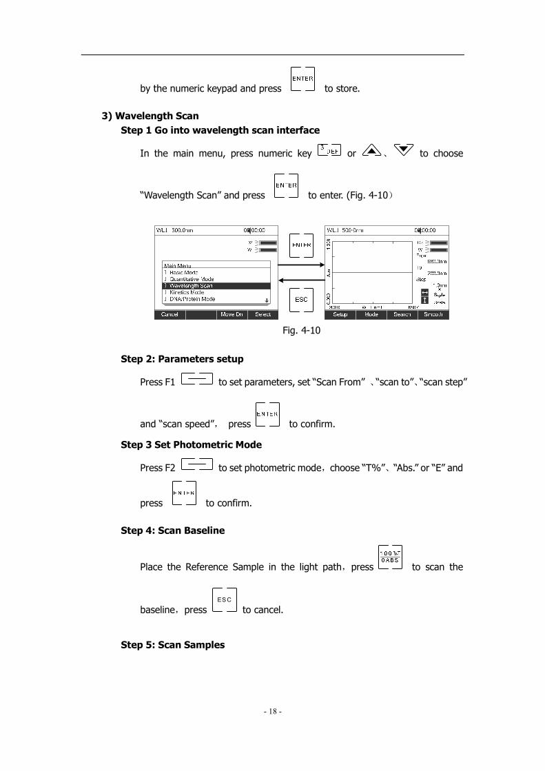
3) Wavelength Scan
Step 1 Go into wavelength scan interface
In the main menu, press numeric key or 、 to choose
“Wavelength Scan” and press to enter. (Fig. 4-10)
Fig. 4-10
Step 2: Parameters setup
Press F1 to set parameters, set “Scan From” 、“scan to”、“scan step”
and “scan speed”, press to confirm.
Step 3 Set Photometric Mode
Press F2 to set photometric mode,choose “T%”、“Abs.” or “E” and
press to confirm.
Step 4: Scan Baseline
Place the Reference Sample in the light path,press to scan the
baseline,press ES C
to cancel.
Step 5: Scan Samples
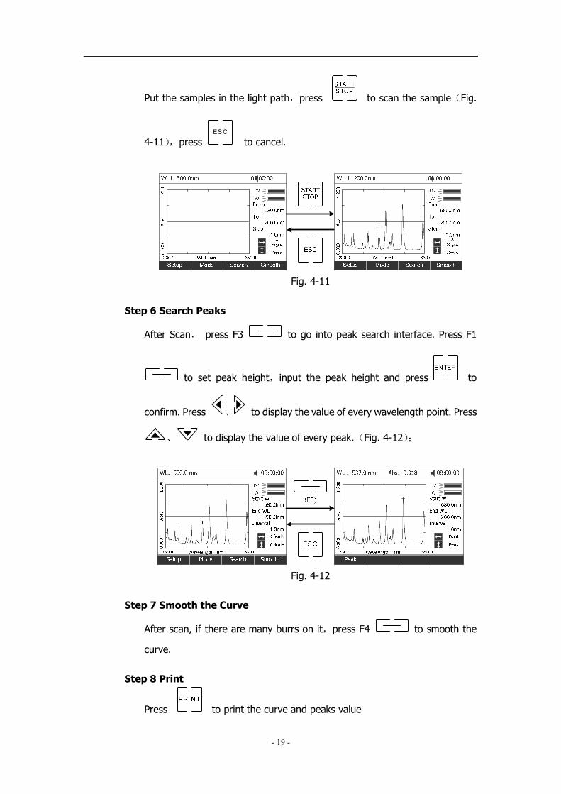
- 19 -
Put the samples in the light path,press to scan the sample(Fig.
4-11),press ES C
to cancel.
Fig. 4-11
Step 6 Search Peaks
After Scan, press F3 to go into peak search interface. Press F1
to set peak height,input the peak height and press to
confirm. Press 、 to display the value of every wavelength point. Press
、 to display the value of every peak.(Fig. 4-12);
Fig. 4-12
Step 7 Smooth the Curve
After scan, if there are many burrs on it,press F4 to smooth the
curve.
Step 8 Print
Press to print the curve and peaks value

- 20 -
Step 9 Delete
Press to delete the local curve.
Step 10 Store the curve
After scan,press to go into the store interface. Input the file name
by numeric keypad and press to confirm.
4) Kinetics
Step 1 Go into Kinetics Test Interface
In the main menu, press or 、 to select “Kinetics Mode”
and press to confirm(Fig. 4-13);
Fig. 4-13
Step 2 Setup Parameters
Press F1 to set parameters,input the corresponding values of
“Total Time”, “Delay Time” and “Time Intervals” according the screen
indicates. Press to confirm.
Step 3 Set Photometric Mode
Press F2 to set photometric mode, choose “T%” or “Abs.” and press
to confirm.
Step 4 Set Wavelength

- 21 -
Press to set wavelength, input the value of the wavelength by
numeric keypad and press to confirm.
Step 5 Calibrate 100%T/0Abs
Put the Reference Sample in the light path, press to calibrate
100%T/0Abs;
Step 6 Measure the sample
Put the sample to be tested in the light path and press to begin the
test(Fig. 4-14),press ES C
to cancel.
Fig. 4-14
Step 7 Calculate Response Rate
After time scan, if users want to calculate the response rate of some period,
you can press F3 to go into “Process” interface. Input the values of
“Begin Time”, “End Time” and “Factor” separately and press to
confirm. Then the value of “I.U.” would display on the screen. (Fig.4-15)
Fig. 4-15
Step 8 Search

- 22 -
After scan finished, press F4 to go into search mode. Press 、
to search the value of every point.(Fig. 4-16);
Fig. 4-16
Step 9: Print
Press to print curve.
Step 10: Delete the Curve
Press to delete the local curve
Step 11 Save the Curve
After scan, press to save, input the file name by the numeric
keypad. Press to confirm.
5) DNA/Protein Mode
Step 1: Go into DNA/Protein Test
In the Main menu,press or 、 to choose “DNA/Protein
Mode” and press to confirm.(Fig. 4-17)
- 23 -
Fig. 4-17
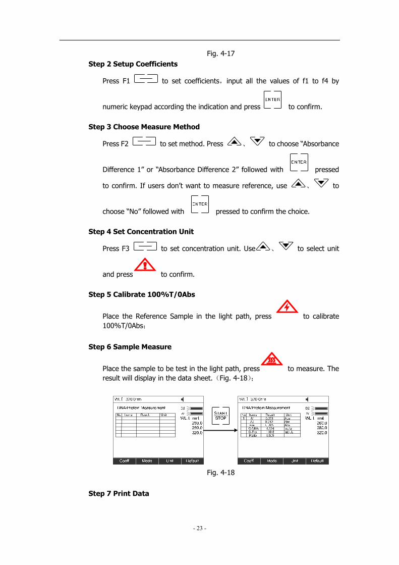
Step 2 Setup Coefficients
Press F1 to set coefficients,input all the values of f1 to f4 by
numeric keypad according the indication and press to confirm.
Step 3 Choose Measure Method
Press F2 to set method. Press 、 to choose “Absorbance
Difference 1” or “Absorbance Difference 2” followed with pressed
to confirm. If users don’t want to measure reference, use 、 to
choose “No” followed with pressed to confirm the choice.
Step 4 Set Concentration Unit
Press F3 to set concentration unit. Use 、 to select unit
and press to confirm.
Step 5 Calibrate 100%T/0Abs
Place the Reference Sample in the light path, press to calibrate
100%T/0Abs;
Step 6 Sample Measure
Place the sample to be test in the light path, press to measure. The
result will display in the data sheet.(Fig. 4-18);
Fig. 4-18
Step 7 Print Data

- 24 -
Press to print the result;
Step 8 Delete Data
Press to delete the data;
Step 9 Store the Data
After measurement, press to store the result. Input the file name
by the numeric keypad, press to confirm.
6) Multi Wavelength Mode
Step 1: Go into Multi Wavelength Measurement
In the Main Menu,Press or 、 to choose “Multi Wavelength
Measurement” and then press to go into multi wavelength
measurement interface.(Fig. 4-19)
Fig. 4-19
Step 2 Setup Wavelength
Press F1 to go into wavelength setting interface,input all the
wavelength value one by one by the numeric keypad. Press to
confirm, press ES C
to return.
Step 3 Set Photometric Mode

- 25 -
Press F2 to set the photometric mode, use 、 to select
“Abs. ” or “T%” mode, press to confirm.
Step 4 Calibrate 100%T/0Abs
Place the Reference Sample in the light path, press to calibrate
100%T/0Abs;
Step 5 Measure Sample
Place the sample to be test in the light path,press to measure,the
test result will display in the data sheet.(Fig. 4-20);
Fig. 4-20
Step 6 Print Data
Press to print the result
Step 7 Delete Data
Press to delete the data
Step 8 Store the Data
After measurement, press to store the result. Input the file name
by the numeric keypad and press to confirm.
5. System Utility

- 26 -
In the main menu,press or use 、 to select “System Utility” and
press to confirm.(Fig. 4-21)
Fig. 4-21
1) Wavelength Reset
After some time, the energy of lights would drop off and there
will be some but slight influence on the test result. In this case,
user’s can reset the wavelength to compensate. We suggest
the user’s to reset the wavelength every one or two months.
Press or use 、 to choose “Wavelength Reset” then press
to begin the calibration. During the course, opening the lid of the
compartment is prohibited.
2) Printer Setup
Press or 、 to select “Printer Setup” then press to
confirm.(Fig. 4-22)
Fig. 4-22
� Reset Printer
- 27 -
Press or use 、 to choose “Reset Printer” and press
to confirm. Then the printer will resume the initial condition.
� Select print port
Press or use 、 to choose “Select print port” and press
to confirm. Use 、 to choose “LPT” or “Comm” and
then press to confirm.
� Select Printer
Press or use 、 to choose “Select printer” and press
to confirm. Use 、 to select the printer’s model and
then press to confirm.
� Change Print Mode
Press or use 、 to choose “Change print mode” and
press to confirm. Two modes are under your choice, one is
“Print Data Sheet”, the other is “print the display interface”
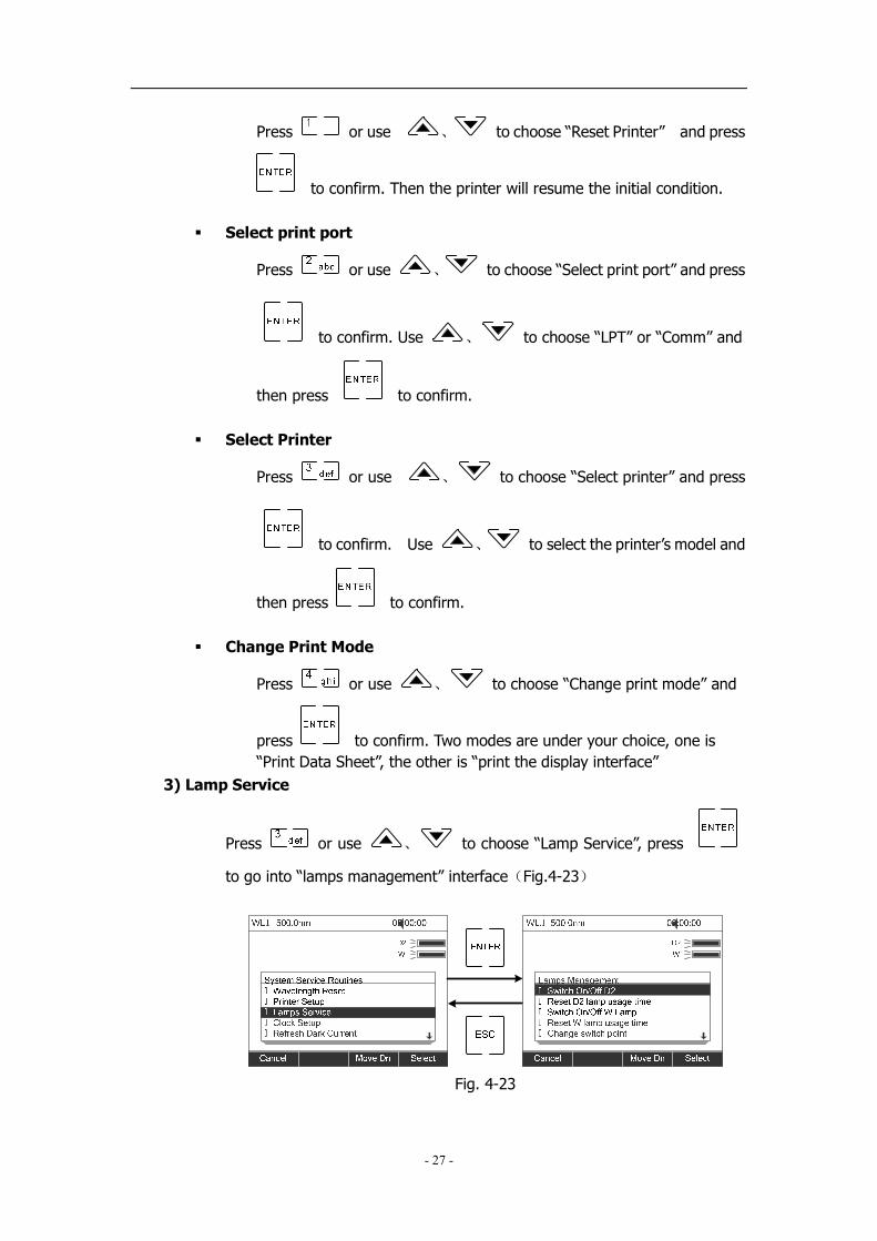
3) Lamp Service
Press or use 、 to choose “Lamp Service”, press
to go into “lamps management” interface(Fig.4-23)
Fig. 4-23

- 28 -
� Switch On/Off D2 lamp
Users can switch Off the D2 Lamp when test in the wavelength
range of 340-1100nm, so as to prolong the life time of D2 lamp.
Press or 、 to choose “Switch On/Off D2 lamp” then
press to switch on or switch off the D2 lamp
� Reset the usage time of D2 lamp
After some period of usage(About 1000h)))), the energy would
drop off to a low level,,,,and the test data in the UV range would
get instable and deviate a lot from the experiential value.
Then the D2 lamp should be replaced to a new one.After
replacement, users shoud calibrate the wavelength again.
Press or use 、 to choose “Reset D2 lamp usage time”
and press . Then users can find the D2 lamp’s usage time and the
system will ask if you are sure to reset the usage time. Press 、 to
choose “Yes” and then press to confirm. The system will record
the usage time from zero.
� Switch On/Off W lamp
Users can switch Off the D2 Lamp when test in the wavelength
range of 190-339nm, so as to prolong the life time of D2 lamp.
Press or use 、 to choose “Reset W lamp usage time”
and press . Then users can find the W lamp’s usage time and
the system will ask you if are sure to reset the usage time.
� Reset the W lamp usage time
After some period of usage(About 1500h)))), the energy would
drop off to a low level,,,,and the test data in the Visible range
would get instable and deviate a lot from the experiential
value. Then the W lamp should be replaced to a new one.After
replacement, users shoud calibrate the wavelength again.
- 29 -
Press or use 、 to choose “Reset W lamp usage time”
and press . Then users can find the W lamp’s usage time and
the system will ask if you are sure to reset the usage time. Press 、
to choose “Yes” and then press to confirm. The
system will record the usage time from zero.
� Change Switch point
The instrument permits the users to set the lamps changing
wavelength point. In the range of 325—375, users can choose
the lamp freely.
Press or use 、 to choose “Change Switch point”
and press to confirm. Input the wavelength point value
(325—375nm) and press to confirm.
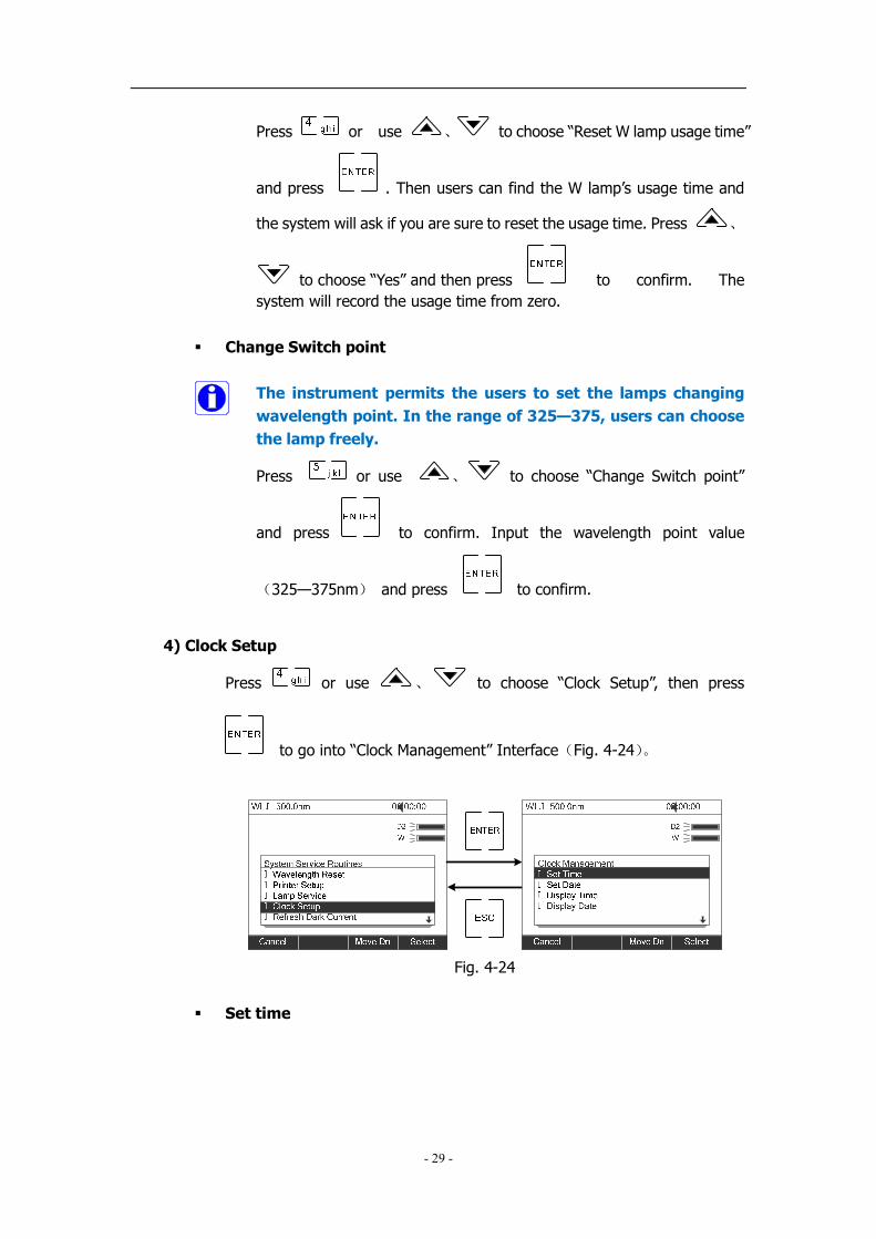
4) Clock Setup
Press or use 、 to choose “Clock Setup”, then press
to go into “Clock Management” Interface(Fig. 4-24)。
Fig. 4-24
� Set time
- 30 -
Press or 、 to choose “Set Time” and press to
confirm. Input the time (Hour, Minute, Second) by numeric keypad, press
to confirm and return automatically.
� Set Date
Press or use 、 to choose “Set Date” and press
to confirm. Input the Date(Year,Month,Day) by numeric
keypad, press to confirm and return automatically.
� Display Time
Press or use 、 to choose “Display Time” and press
to confirm. Then the time will display on the Right Top corner.
� Display Date
Press or use 、 to choose “Display Date” and press
to confirm. Then the Date will display on the Right Top corner.
5) Refresh Dark Current
When the working environment changed, users should refresh
Dark Current before test.
Press or use 、 to choose “Refresh Dark Current” and
press to confirm. Then the system begins to refresh Dark Current.
Note: During the course, open the lid of the compartment is prohibited.
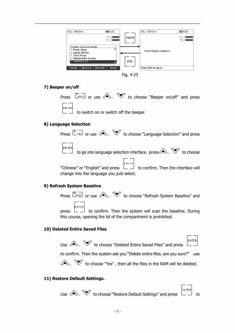
6) Connect to PC
Press or use 、 to choose “Connect to PC”, and press
to go into waiting interface.(Fig. 4-25) When the instrument was
connected to PC, it displays “Controlled by PC”
- 31 -
Fig. 4-25
7) Beeper on/off
Press or use 、 to choose “Beeper on/off” and press
to switch on or switch off the beeper.
8) Language Selection
Press or use 、 to choose “Language Selection” and press
to go into language selection interface,press 、 to choose
“Chinese” or “English” and press to confirm. Then the interface will
change into the language you just select.
9) Refresh System Baseline
Press or use 、 to choose “Refresh System Baseline” and
press to confirm. Then the system will scan the baseline. During
this course, opening the lid of the compartment is prohibited.
10) Deleted Entire Saved Files
Use 、 to choose “Deleted Entire Saved Files” and press
to confirm. Then the system ask you “Delete entire files, are you sure?” use
、 to choose “Yes” , then all the files in the RAM will be deleted.
11) Restore Default Settings.
Use 、 to choose “Restore Default Settings” and press to

- 32 -
Confirm, then the system will restore the initialization.
12) Setup Slot((((Only available for variable bandwidth models))))
In the main menu, press or use 、 to choose “Setup Slot”
and press to confirm(Fig. 4-26). Press 、 to choose
“0.5nm”、“1.0nm”、“2.0nm” or “4.0nm” then press to confirm.

- 33 -
Chapter V Instrument Maintenance
To keep the instrument work in good condition, constant maintain is needed.
1. Daily Maintain
1) Check the compartment
After measurement, the cuvettes with sample solutions should be taken out of the
compartment in time. Or the volatilization of the solution would make the mirror
go moldy. Users must pay more attention to the corrosive sample and liquid easy
to volatilize. Any solution remains in the compartment should be wipe off
immediately.
2) Surface Clean
The cover of the instrument is with paint. Please use wet towel to wipe off the
drips on the surface immediately. Organic solution is forbidden to be used to clean
the cover. Please wipe off the dirt on the cover timely.
3) Clean the cuvettes
After every test or after a solution change, the cuvettes should be cleaned carefully,
or the remains on the surface would cause measuring error.
2. Troubleshooting
1) Dark Current Error when self-test
Possible Cause Solution
� Open the lid of the compartment Close the lid of the compartment
during the course of self-test. and switch on the power again.
2) No response after power on
Possible Cause Solution
� Bad contact in power supply Improve the contact
� Fuse melt Replace a new fuse
3) Printer not work, printer error
Possible Cause Solution
� No power supply Switch on the power supply
� Bad contact in power supply Improve the contact
� Bad contact of the data cable Improve the contact
4) No Stable Reading
Possible Cause Solution
� No enough pre-warm Increase the pre-warm time
� Glass cuvettes used in UV Range Use Silicon Cuvettes.
� No stable Sample Improve the sample
� Much higher sample concentration Dilute the sample
- 34 -
� Low voltage or unstable power supply Improve the power condition
� Lights defect Replace a new lamp
� Light used up Replace a new lamp
5) Worse Repeatability
Possible Reason Solution
� Unstable sample Improve the sample
� Cuvettes polluted Clean the cuvettes
6) Incorrect reading
Possible Reason Solution
� Dark Current Error Re-get the dark current
� Worse matching of the cuvettes Improve the matching of the cuvettes
3. Spare parts replacement
1) Replace the fuse
Danger! Be sure to switch off the power and unplug the socket
before replacement!
Step 1: Tools preparation
Prepare a 3×75 Flat Blade screwdriver
Step2::::Switch Off the power supply
Switch off the power supply, and unplug the socket.
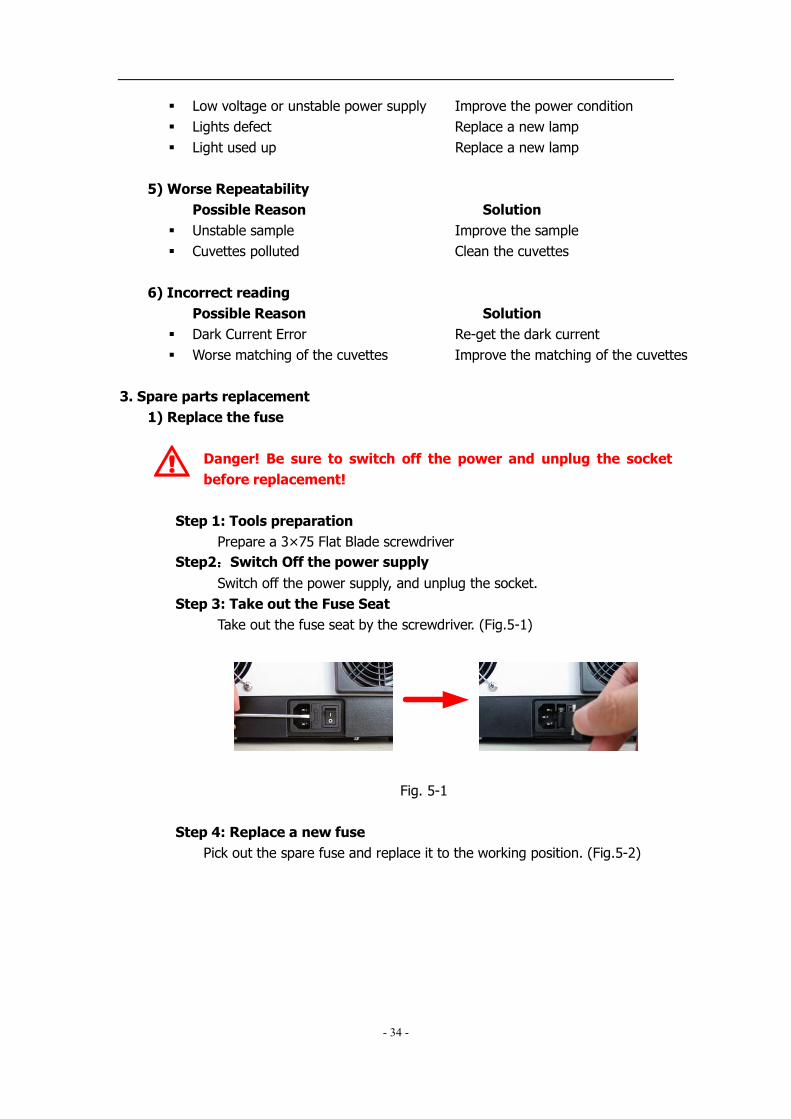
Step 3: Take out the Fuse Seat
Take out the fuse seat by the screwdriver. (Fig.5-1)
Fig. 5-1
Step 4: Replace a new fuse
Pick out the spare fuse and replace it to the working position. (Fig.5-2)

- 35 -
Fig. 5-2
Step 5: Reset the fuse seat
Replace the fuse seat in the power socket
Step 6: Switch on the power
Plug the socket and switch on the power
2) Replace lamps
High temperature!!!! Wait 20 minutes before open the lamp
chamber after power off to avoid scald!
Step 1 Tools preparation
Prepare a 6×150mm Cross Blade screwdriver and a pair of glove.
Step 2 Power Off
Switch off the power supply and unplug the socket.
Step 3: Open the cover
Unscrew the 4 screws indicated in Fig.5-3(Each side with 2 screws),then
unscrew the pole of the compartment and remove the cover.
Fig. 5-3

- 36 -
Step 4: Open the cover of the light chamber
Unscrew the 2 screws on the light chamber cover and remove it. (Fig.5-4)
Fig. 5-4
Step 5: Replace the D2 Lamp
Unscrew the 2 screws on the D2 Flange (No.1 in Fig. 5-5), unplug the
connector in the power board(No. 2)and remove the D2 lamp. Draw on the
cotton glove and replace a new lamp. Fix the 2 screws and plug the
connector again.
Fig. 5-5
Step 6: Replace W lamp
Remember the direction of the filament before pull out the W
lamp. Be sure that the new lamp’s filament is in the same
direction as before.
Pull out the defected W lamp and draw on the cotton glove. Insert the new W
lamp as deep as possible on the lamp seat. Be sure to keep the filament in

- 37 -
the same direction as the old one face.
Fig. 5-6
Step 7 Adjust the position of the W lamp
Switch on the power,(the Switch Mirror should be placed to the position as
Fig. 5-7 indicates). Observe the entrance facula,and it should in the center
of the entrance hole. (Fig.5-7)
If the facula deviate to Left or Right, then loosen the No.1 screws in Fig. 5-8
and move the lamp seat to Left or Right until it focus on the center of the slot.
Then fix the screws.
If the facula deviate to Up and Down, then loosen the No.2 screws in Fig. 5-8
and move the lamp seat Up and Down until the facula focus on the center of
the slot. Then fix the No. 2 screws again.
Fig. 5-7

- 38 -
Fig. 5-8
Step 8 Finish
Reset the cover of the light chamber and fix the screws. Reset the cover of
the instrument and fix the screws. Recover the Pole in the compartment,
then the course finished.
3) Replace the Battery
Be sure to switch off the power supply and unplug the socket
before open the Bottom Cover!!!!
Step 1: Prepare the tools
Prepare a 6×150mm Cross Blade Screwdriver
Step 2: Switch off the power supply
Switch off the power supply and unplug the socket
Step 3: Open the Bottom cover plate
Unscrew the 13 screws indicated in Fig.5-9 then remove the bottom plate.
Fig. 5-9
Step 4: Replace the Battery

- 39 -
Pick out the old battery and replace a new one. (Fig. 5-10)
Fig. 5-10
Step 5: Finish
Recover the bottom plate and fix the 13 screws, then the course finishes.