Embed Size (px)
Citation preview

1/2" MODEL 3 6 1 2 B R 1/2" MODEL 3612BRA
Equipped with electric brake
Collet chuck capacity
1 i 2 "
INSTRUCTION MANUAL
- Main body No load speed 0 vera I I Net
stroke (RPM) length weight
287 m m 5.7 kg 11 1-5/16") (12.7 lbs)
~ _ _ ~ ~ ~ - . _ _ _ _ _ . ~ ~ ~ ~ ~ _ _ _ ~ ~ ~~
23,000 0 65" (0 ~~ 2-9/16")
DOUBLE INSULATION

IMPORTANT SAFETY INSTRUCTIONS
(For All Tools)
WARNING: WHEN USING ELECTRIC TOOLS, BASIC SAFETY PRECAUTIONS SHOULD ALWAYS BE FOLLOWED TO REDUCE THE RISK OF FIRE, ELECTRIC SHOCK, AND PERSONAL INJURY, INCLUDING THE FOLLOWING:
READ ALL INSTRUCTIONS. 1. KEEP WORK AREA CLEAN. Cluttered areas and benches invite injuries. 2. CONSIDER WORK AREA ENVIRONMENT. Don't use power tools in damp
or wet locations. Keep work area well lit. Don't expose power tools t o rain. Don't use tool in presence of flammable liquids or gases.
3. KEEP CHILDREN AWAY. All visitors should be kept away from work area. Don't let visitors contact tool or extension cord.
4. STORE IDLE TOOLS. When not in use, tools should be stored in dry, and high or locked-up place - out of reach of children.
5. DON'T FORCE TOOL. It will do the job better and safer at the rate for which it was intended.
6. USE RIGHT TOOL. Don't force small tool or attachment t o do the job of a heavy-duty tool. Don't use tool for purpose not intended; for example, don't use circular saw for cutting tree limbs or logs.
7. DRESS PROPERLY. Don't wear loose clothing or jewelry. They can be caught in moving parts. Rubber gloves and non-skid footwear are recommended when working outdoors. Wear protective hair covering t o contain long hair.
8. USE SAFETY GLASSES. Also use face or dust mask if cutting operation is dusty.
9. DON'T ABUSE CORD. Never carry tool by cord or yank it t o disconnect from receptacle. Keep cord from heat, oil, and sharp edges.
IO. SECURE WORK. Use clamps or a vise to hold work. It's safer than using your hand and it frees both hands to operate tool.
11. DON'T OVERREACH. Keep proper footing and balance at all times. 12. MAINTAIN TOOLS WITH CARE. Keep tools sharp and clean for better and
safer performance. Follow instructions for lubricating and changing acces- sories. Inspect tool cords periodically and if damaged, have repaired by autho- rized service facility. Inspect extension cords periodically and replace if damaged. Keep handles dry, clean, and free from oil and grease.
13. DISCONNECT TOOLS. When not in use, before servicing, and when chang- ing accessories, such as blades, bits, cutters.

14. REMOVE ADJUSTING KEYS AND WRENCHES. Form habit of checking t o see that keys and adjusting wrenches are removed from tool before turning it on.
15. AVOID UNINTENTIONAL STARTING. Don't carry tool with finger on switch. Be sure switch is OFF when plugging in.
16. EXTENSION CORDS. Make sure your extension cord is in good condition. When using an extension cord, be sure t o use one heavy enough t o carry the current your product will draw. A n undersized cord will cause a drop in line voltage resulting in loss of power and overheating. Table 1 shows the correct size to use depending on cord length and nameplate ampere rating. If in doubt, use the next heavier gage. The smaller the gage number, the heavier the cord.
TABLE 1 MINIMUM GAGE FOR CORD SETS
Total Length of Cord in Feet
0 - 25
Ampere Rating More Not More Than Than
26 - 50 51 - 100 101 - 150
0 - 6 6 - 10
10 - 12 12 16
18 18 16 14
16 16 14 16 14 12 16 14 12 12 Not Recommended
17. OUTDOOR USE EXTENSION CORDS. When tool is used outdoors, use only extension cords intended for use outdoors and so marked.
18. STAY ALERT. Watch what you are doing, use common sense. Don't operate tool when you are tired.
19. CHECK DAMAGED PARTS. Before further use of the tool, a guard or other part that is damaged should be carefully checked t o determine that it will operate properly and perform i ts intended function. Check for alignment of moving parts, binding of moving parts, breakage of parts, mounting, and any other conditions that may affect its operation. A guard or other part that is damaged should be properly repaired or replaced by an authorized serv- ice center unless otherwise indicated elsewhere in this instruction manual. Have defective switches replaced by authorized service center. Don't use tool if switch does not turn it on and off.
20. GUARD AGAINST ELECTRIC SHOCK. Prevent body contact with grounded surfaces. For example; pipes, radiators, ranges, refrigerator enclosures.
21 . REPLACEMENT PARTS. When servicing. use only identical replacement parts.
22. POLARIZED PLUGS. To reduce the risk of electric shock, this equipment has a polarized plug (one blade is wider than the other). This plug will f i t in a polarized outlet only one way. If the plug does not f i t fully in the outlet, reverse the plug. If it still does not fit, contact a qualified electrician t o install the proper outlet. Do not change the plug in any way.
3
VOLTAGE WARNING: Before connecting the tool t o a power source (receptacle, outlet, etc.) be sure the voltage supplied is the same as that specified on the nameplate of the tool. A power source wi th voltage greater than that specified for the tool can result in SERIOUS INJURY to the user - as well as damage t o the tool. If in doubt, DO NOT PLUG IN THE TOOL. Using a power source w i th voltage less than the nameplate rating is harmful t o the motor.
ADDITIONAL SAFETY RULES 1. Handle the bits very carefully. 2. Check the bit carefully for cracks or damage before operation. Replace
3. Avoid cutting nails. Inspect for and remove all nails from the workpiece be-
4. Hold the tool firmly wi th both hands. 5. Keep hands away from rotating parts. 6. Make sure the bit is not contacting the workpiece before the switch is turned
7. Before using the tool on an actual workpiece, let it run for a while. Watch
8. Be careful of the bit rotating direction and the feed direction. 9. Do not leave the tool running. Operate the tool only when hand-held.
cracked or damaged bit immediately.
fore operation.
on.
for vibration or wobbling that could indicate improperly installed bit.
IO. Always switch off and wait for the bit t o come to a complete stop before
11. Do not touch the bit immediately after operation; it may be extremely hot
removing the tool from workpiece.
and could burn your skin.
SAVE THESE INSTRUCTIONS.
4
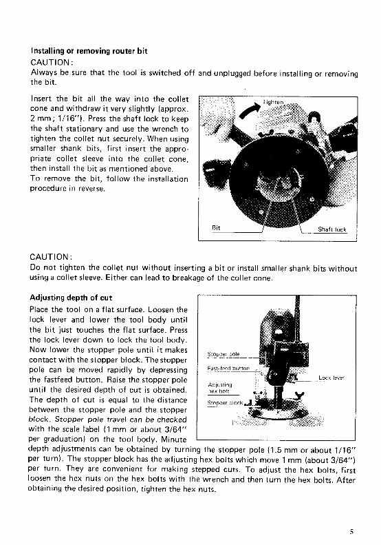
Installing or removing router bit
CAUTION : Always be sure that the tool i s switched off and unplugged before installing or removing the bit.
Insert the bit al l the way into the collet cone and withdraw it very slightly (approx. 2 mm; 1/16"). Press the shaft lock to keep the shaft stationary and use the wrench to tighten the collet nut securely. When using smaller shank bits, first insert the appro- priate collet sleeve into the collet cone, then install the bit as mentioned above. To remove the bit, follow the installation procedure in reverse.
CAUTION : Do not tighten the collet nut without inserting a bit or install smaller shank bits without using a collet sleeve. Either can lead to breakage of the collet cone.
Adjusting depth of cut
Place the tool on a flat surface. Loosen the lock lever and lower the tool body until the bit just touches the flat surface. Press the lock lever down to lock the tool body. Now lower the stopper pole until it makes contact with the stopper block. The stopper pole can be moved rapidly by depressing the fastfeed button. Raise the stopper pole until the desired depth of cut i s obtained. The depth of cut is equal to the distance between the stopper pole and the stopper block. Stopper pole travel can be checked with the scale label (1 mm or about 3/64" per graduation) on the tool body. Minute depth adjustments can be obtained by turning the stopper pole (1.5 mm or about 1/16" per turn). The stopper block has the adjusting hex bolts which move 1 mm (about 3/64") per turn. They are convenient for making stepped cuts. To adjust the hex bolts, first loosen the hex nuts on the hex bolts with the wrench and then turn the hex bolts. After obtaining the desired position, tighten the hex nuts.
5

By turning the nylon nut, the upper limit of the tool body can be adjusted. When the tip of the bit i s retracted more than re- quired in relation to the base plate surface, turn the nylon nut to lower the upper limit.
CAUTION : 0 Do not lower the nylon nut too low or the bit will protrude dangerously.
0 Before operating the tool, check to be sure that the router automatically rises to the upper limit.
0Since excessive cutting may cause overload of the motor or difficulty in controlling the tool, the depth of cut should not be more than 15 mm (5/8") a t a pass when cutting grooves. When you wish to cut grooves more than 15 mm (5/8") deep, make several passes with progressively deeper bit settings.
Switch action To start the tool, move the switch lever to the "ON" position. To stop, move the switch lever to the "OFF" position.
CAUTION : Make sure the shaft lock is released before the switch is turned on.
Operation 0Set the tool base on the workpiece to be cut without the bit making any contact. Then
turn the tool on and wait until the bit attains full speed. Lower the tool body and move the tool forward over the workpiece surface, keeping the tool base flush and advancing smoothly until the cutting is complete.
0 When doing edge cutting, the workpiece surface should be on the left side of the bit in the feed direction. (see the figure below).
Bit revolving direction
Feed direction
(View from the top of the tool)
Correct bit feed direction
6

NOTE : 0 Moving the tool forward too fast may cause a poor quality of cut, or damage to the bit
or motor. Moving the tool forward too slowly may burn and mar the cut. The proper feed rate will depend on the bit size, the kind of workpiece and depth of cut. Before beginning the cut on the actual workpiece, it i s advisable to make a sample cut on a piece of scrap lumber. This will show exactly how the cut will look as well as enable you to check dimensions.
When using the straight guide or the trimmer guide, be sure to install it on the right side in the feed direction. This will help to keep it flush with the side of the workpiece.
Straight guide (Optional accessory) The straight guide i s effectively used for straight cuts when chamfering or grooving.
Install the straight guide on the guide holder with the wing bolt (B) . Tighten the wing bolt (B) only tight enough to hold the straight guide temporarily. Then insert the guide holder into the holes in the tool base and tighten the wing bolts (A). Adjust the distance between the bit and the straight guide by turning the fine adjusting screw (1.5 mm or about 1/16” per turn.) At the desired distance, tighten the wing bolt (B) to secure the straight guide in place.
When cutting, move the tool with the straight guide flush with the side of the workpiece.
Wider straight guide of desired dimensions may be made by using the convenient holes in the guide to bolt on extra pieces of wood. When using a board-jointing bit, attach pieces of wood to the straight guide which have a thickness of more than 15 mm (5/8”) so that the bit does not strike the straight guide.
Wins bolt (6)
Wing bolt (A )
Straight guide
More than
115” (5’8”)
7
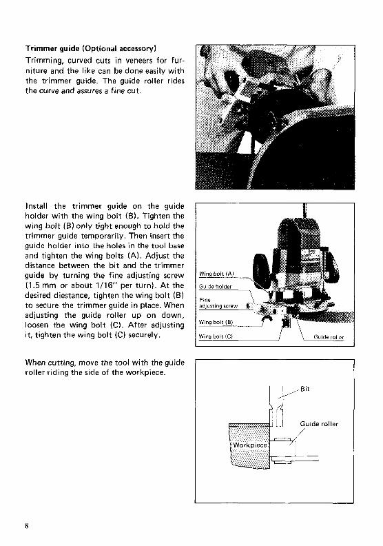
Trimmer guide (Optional accessory) Trimming, curved cuts in veneers for fur- niture and the like can be done easily with the trimmer guide. The guide roller rides the curve and assures a fine cut.
Install the trimmer guide on the guide holder with the wing bolt (6). Tighten the wing bolt (B) only tight enough to hold the trimmer guide temporarily. Then insert the guide holder into the holes in the tool base and tighten the wing bolts (A). Adjust the distance between the bit and the trimmer guide by turning the fine adjusting screw (1.5 mm or about 1/16" per turn). At the desired diestance, tighten the wing bolt (6) to secure the trimmer guide in place. When adjusting the guide roller up on down, loosen the wing bolt (C ) . After adjusting it, tighten the wing bolt ( C ) securely.
When cutting, move the tool with the guide roller riding the side of the workpiece.
Wing bolt (C) I \ Guide roller
4 Guide roller
8

Templet guide (Optional accessory) The templet guide provides a sleeve through which the bit passes, allowing use of the router with templet patterns.
To install the templet guide, loosen the screws on the tool base, insert the templet Base plate Templet guide
I
guide and then tighten the screws
Secure the templet to the workpiece. Place the tool on the templet and move the tool with the templet guide sliding along the side of the templet.
I Screw V
Bit ~ Tjmplet guide
9

MAINTENANCE CAUTION : Always be sure that the tool is switched off and unplugged before attempting to perform inspection or maintenance.
Replacing carbon brushes Remove and check the carbon brushes regularly. Replace when they wear down to the limit mark. Keep the carbon brushes clean and free to slip in the holders. Both carbon brushes should be replaced a t the same time. Use only identical carbon brushes. If ohter type of carbon brushes are em- ployed in tools equipped with an electric brake, the electric brake may not operate properly.
/ Limit mark
Use a screwdriver to remove the brush 1 holder caps. Take out the worn carbon brushes, insert the new ones and secure the brush holder caps.
Brush holder cap 7 1 I I Screwdriver
To maintain product SAFETY and RELIABILITY, repairs, any other maintenance or adjustment should be performed by Makita Authorized or Factory Service Centers, always using Makita replacement parts.

ACCESSORIES CAUTION : These accessories or attachments are recommended for use with your Makita tool specified in this manual. The use of any other accessories or attachments might present a risk of injury to persons. The accessories or attachments should be used only in the proper and intended manner.
0 Templet guide
1
0 Collet sleeve Use a sleeve which fits for the diameter of the bi t shank.
, " I *
0 Straight guide Part NO. 342428-9
0 Wrench 24 Part No. 781 210-5
0 Wrench 8 Part No. 781 21 3-9
0 Templet guide 25
lmml Part No I Tompler g u f d e I A I B I C
321812 1 I 25 122 6 157164") 1 2 5 4 ll"1 I 11 17116'1
0 Lock nut (for templet guide 25) Part No. 252627-4
0 Templet guide adapter (for templet guide 25)
0 Trimmer guide Par t No. 123022-4
0 Guide holder Par t No. 132306-9

Bits STRAIGHT - Single Flute
7330054A 318 1 1-114 112 2.112 733005-6A 112 1-114 1-7/16 112 2-718 733005-8A 112 1.112 1.114 112 3 733006-4A 314 1-114 1-114 112 2-112 733006-6A 718 1-114 1-3116 1 I2 2-112
, 733006-8A 1 1-114 1-3/16 112 2-112
CARBIDE TIPPED
PART NO. A 8 C D E
733002-0A 318 1 1-1 I 2 112 2.314 733002-4A 112 1-114 1-318 112 2-718
HIGH SPEED STEEL
PART NO. A E C D E
733232-6A 1 I 8 5/16 1-118 114 1-518
STRAIGHT - 2 Flute
- ID+ CARBIDE TIPPED
PART NO. A E C D E
733003-2A 3/16 7/16 1-318 114 2 733003-4A 114 314 1-3/16 1 I 4 2-118 733003-8A 5/16 1 1-118 114 2-3/16
HIGH SPEED STEEL (STRAIGHT - 2 Flute)
I PARTNO. A B C D E I 7332334A 5/16 718 1-3/16 114 2-1 I8 733234-2A 112 718 1-118 1 I 4 2-1 I8
STRAIGHT - 2 Flute, 1/2"Shank
I D i -
CARBIDE TIPPED
I PARTNO. A B C D E
HINGE MORTISING
CARBIDE TIPPED
PART NO. A B C D E
733006-9A 112 112 1-1116 114 1-13/16
HIGH SPEED STEEL
PART NO. A E C D E
733235-0A 112 112 314 114 1-15/16
12

VEINING -Single Flute
SOLID CARBIDE
A PART NO. E C
733007-SA 3116 7132 1-1 I 4 1-1 12
ROUND NOSE
CARBIDE TIPPED
I PARTNO. A E C D E 1 733008-2A 114 15/32 1-1 14 114 1-718 733008-4A 318 9116 1-114 114 2 733008-6A 112 11116 1-114 1 14 2-3/16 733008-8A 518 11/16 1-114 114 2-1 14 733009-0A 314 13116 1-1 14 114 2-318
CORE BOX
- 4 D C & -J HIGH SPEED STEEL
I PARTNO. A B C D E
I 733238.2~ 114 114 1-3116 114 1-112 1
VEE GROOVING
An/-
CARBIDE TIPPED
PART NO. A E3 C D E a
733009-2A 318 112 1-3/16 1 /4 2 90" 733009~4A 518 3/4 15116 114 2 90"
13

14' DOVETAIL
CARBIDE TIPPED
PART NO A 6 C D E
733009-6A 1 / 2 112 1-1/4 1 I 4 1 -7/8
HIGH SPEED STEEL
PART NO. A B C D E
733239-6A 1 / 2 1 / 2 1 -3/8 1 I 4 2
STAGGER TOOTH
I-Ad
CARBIDE TIPPED
I PARTNO. A B C D E 1 733007-0A 3 /8 1.112 1-1/4 112 3
PNAEL PILOT
CARBIDE TIPPED
PART NO. A B C D E
7330304A 318 1 1 3/8 2-1/2 733030-6A 112 1 118 1.112 1 I2 3-114
HIGH SPEED STEEL
PART NO. A B C D E
733236-0A 114 3/4 1 1 /4 2-7/16
CORNER ROUNDING
A D &
CARBIDE TIPPED - Ball Bearing Pilot
I PARTNO. AI Az 8 C D E R
733120-6A 1-1/4 1-1/4 2-1 18 733120-8A 1-112 314 1-114 2-1 /4
2-3/8 733121-2A 1-1/2 3/4 1-1/2 2-1/2
REPLACEMENT BEARING - N O 733132-4A
HIGH SPEED STEEL - Solid Pilot
3/16 1 14 5/16 3/8 1 / 2 3/8 1 / 2
I PARTNO. A i Az B C D E R
1 733240-2A 11/16 3/16 1/2 1/4 1-3/4 733240-6A 15/16 3/16 5/53 1 1/4 1-7/8 3/8 ll4 I
14

BEADING
CARBIDE TIPPED - Ball Bearing Pilot
7331 21 -4A 7/8 3/8 3/8 1-114 114 1-15/16 3/16 733121-6A 112 3/8 1 /2 1-114 114 114 733121-8A 1~118 112 3/8 112 1-114 114 2-1/16 5 /16 733122-0A 1-114 112 318 518 1-114 114 2-1/8 318 733122-2A 1 1 / 2 112 318 314 1114 114 2-114 112
REPLACEMENT BEARING ~ NO. 733132-2A
CARBIDE TIPPED - Ball Bearing Pilot COVE
733122-6A 718 318 318 1/4 1-5/8 114 733122-8A 1-1/8 318 114 1-314 318 733123-0A 1-3/8 3/8 5 /8 114 1-718 1/2
REPLACEMENT BEARING ~ NO. 733132-2A
HIGH SPEED STEEL solid Pilot
PARTNO. A i A2 B C D E R
733242.6A 11116 3/16 1/2 1 1 /4 1-314 1/4 733242-8A 15/16 3/16 3/4 1 114 2-1/32 318
45" CHAMFERING
CARBIDE TIPPED - Ball Bearing Pilot
PART NO AI A2 B C D E
733124-4A 1 3 / 1 6 112 1 /2 1-1/4 1/4 2-1/4
REPLACEMENT BEARING - NO 733132 4A
RABBETING
4 O l -
CARBIDE TIPPED - Ball Bearing Pilot
PART NO AI A2 B C D E
733124-2A 1-114 112 112 1-7/16 114 2-1/4
I REPLACEMENT BEARING - NO 733132-4A I
15

ROMAN OGEE
CARBIDE TIPPED - Ball Bearing Pilot
P A R T N O A, A2 B C D E R
733123-2A 1 3/8 15/32 1-1/4 114 2 5/32 733123 4A 1-318 3/8 21/32 1-1/4 1/4 2-1/8 114
REPLACEMENT BEARING - NO 733132-2A
FLUSH TRIMMER - Self Piloting
SOLID CARBIDE
PART NO. A B C D E
733128-0A 1 /4 1 /4 1-1/16 114 1-9/16
7' BEVEL TRIMMER - Self-Piloting
SOLID CARBIDE
PART NO. A B C D E
733128-2A 3/16 1 I4 1-1/16 114 1-9/16
~~ ~
2 FLUTE FLUSH TRIMMER
CARBIDE TIPPED
PART NO.
7331 28-8A 1-114 2-1/16 733128-9A 1-1/4 2-1/16 7331 29-OA 112 1.114 2-518
3/8" REPLACEMENT BEARING - NO. 733132-2A 1/2" REPLACEMENT BEARING - N O . 7331324A
16

COMBINATION FLUSH/22" BEVEL TRIMMER
4 D C
CARBIDE TIPPED
PART NO A B I 62 C D E
7331 28-6A 711 6 112 3/16 1-114 114 1-314
3 FLUTE FLUSH TRIMMER ASSEMBLY - Self Piloting
SOLID CARBIDE CUTTER
PART NO. A B C D E
733129-2A 518 318 1-114 114 2-318
REPLACEMENT BEARING - NO. 733132-6A
3 FLUTE 22" BEVEL TRIMMER ASSEMBLY -Self Piloting
-ID!-
SOLID CARBIDE CUTTER
P A R T N O . AI A2 B C D E
733129-4A 718 5/8 3/8 1-114 114 2-318
REPLACEMENT BEARING - NO. 733132~6A
3 F L U T E FLUSHREPLACEMENTCUTTER
SOLID CARBIDE
I P A R T N O A B D
7331 29-6A 518 3/8 114
FOR FLUSH TRIMMER ASSEMBLY NO. 733129-2A
17

3 FLUTE 22" BEVEL REPLACEMENT CUTTER
SOLID CARBIDE
I PARTNO. A B D 1 733129-8A 7 /8 3/8 1 /4
FOR BEVEL TRIMMER ASSEMBLY NO. 733129-4A
114" REPLACEMENT ARBOR
PART NO. A 8 C D E
733131-2A 5/8 3/8 1-1/4 114 2-3/8
L A 4 FOR FLUSH TRIMMER ASSEMBLY NO. 733129-2A AND NO. 733129-4A
BALL BEARING PILOT
I PARTNO. D l D2 I 7331 32-2A 3/8 0 D 7331 32-4A 1/2 O D 7331 32-6A 5/8 0 D
1/8 1.D 3/16 I D. 1/4 1.D
18
Feb-20--'92 US
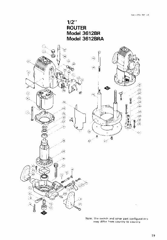
1/2" ROUTER Model 3612BR Model 3612BRA
Note: The s w i t c h and o ther par t con f igura t ions m a y di f fer f r o m c o u n t r y to country .
19

Feb-20- 92 US
ILLM ,";, DESCRIPTION ILLM ,"zD DESCRIPTION
MACHINE MACHINE
1 2 3 4 5 6 I 8 9
10 11 12 13 14 15 16 17 18 19 20 21 22 23 24 25 26 27 28 29 30
31 32
1 1 1 1 4 1 2 4 1 1 1 1 1 4 1 1 2 1 1 1 1 1 1 1 1 1 1 1 1 1
1 1 -
Nut M10 Nylon Nut M10 Motor Housing Name Plate Rivet 0-5 FIELD ASSEMBLY Hex Bolt M5xB5 (With Washer1 Countersunk Head Screw M4x14 IWith Washer] Ball Bearing 2012LLB Knob L Motor Bracket Compression Spring 10 Half Nut Pan Head Screw M5x40 IWith Washerl Collet Nut Collet cone Pan Head Screw M6x40 (With Washer) Knob R Compression Spring 15 Set Bolt M10 Lock Lever Spring Washer 5 Hex Bolt M5x12 Retaining Ring R - 12 Pin 6 Compression Spring 7 Screw M10x77 Bearing Retainer 50 Fan 92 ARMATURE ASSEMBLY IWith Item 29 - 321 Insulation Washer Ball Bearina 6200V
33 34 35 36 38 39 40 41 42 43 44 45 46 47 48 49 50 51 52 53 54 55 56 57 58 59 60 81 62 63 6 4 65
-
1 1 1 1 1 2 1 1 2 1 2 2 1 1 1 2 1 2 2 1 1 1 1 1 1 1 1 1 2 4 1 2
- Note The Switch and other part specifications may differ from country to country.
Wave Washer 20 Wing Bolt M5x10 Baffle Plate Chlp Deflector Switch Pan Head Screw M4x16 IWith Washer) Strain Relief Switch Cover Pan Head Screw M4x20 (With Washer) Hex Nut M12 Brush Holder Cap Carbon Brush Cord Guard Cord Pole Compression Spring 11 Base Wing Bolt M5x15 Compression Spring 7 Hex Bolt M5x16 Hex Nut M5 Hex Bolt M5x40 Hex Nut M 5 Flat Head Screw M6 Compression Spring 12 Hex Bolt M5x28 Hex Nut M5
Pan Head Screw M5x10 IWith Washer1 Countersunk Head Screw M4x8 Base Plate Spring Pin 5-18
stopper
MAKlTA LIMITED ONE YEAR WARRANTY 1 Warranty Policy
Cvery Makila tool IS thoroughly inspected and tested before leaving the factory. It IS warranted to be free of defects from workmanship and materials for the penod of ONE YEAR from the date of 1 nncinal ourchaw Should anv trouble develoa durini this one-"ear oeriod. return the COMPLETE Fiz: fre:ght prepaid, i i & of Makita's Factdry or A\thorized Selvtce Centers. If inspection shows the trouble is caused by defective workmanship or material, Makita will repair (or at our option, replace) without charge.
This Warranty does not apply where: repairs have been made or attempted by others: repairs are required because of normal wear and tear The tool has been abused, misused or improperly maintained, alterations have been made to the tool
IN NO EVENT SHALL MAKlTA BE LIABLE FOR ANY INDIRECT, INCIDENTAL OR CON- SEQUENTIAL DAMAGES FROM THE SALE OR USE O F THE PRODUCT. THIS DISCLAIMER APPLIES BOTH DURING AND AFTER THE TERM O F THIS WARRANTY MAKlTA DISCLAIMS LIABILITY FOR ANY IMPLIED WARRANTIES, INCLUDING IMPLIED WARRANTIES O F "MERCHANTABILITY" AND "FITNESS FOR A SPECIFIC PURPOSE,'' AFTER THE ONE-YEAR TERM O F THIS WARRANTY. Tlur Warranty gjves you spefifjc legal nghts. and you may also have other nghts which vary from State to state. Some States d o not allow the exclusion or Imitation of incidental or consequential damages, so the above limitation 01 exclusion may not apply to yo". Some states d o not allow limitation on how long an implied warranty lasts, so the above limitation may not apply to you. !
Ma ki ta Corporation 3-11 -8, Sumiyoshi-cho, Anjo, Aichi 446 Japan
883389J061 PRINTED IN JAPAN 1995 - 4 - N