Embed Size (px)
Citation preview

Mini Cooling Dry Bath Incubator
(Mini Cooler)
Instruction Manual
Catalog No. MC-0203
(programmable cooling and heating capability)
www.majorsci.com
Version 02B
Revised on : 2015.05.08
1
Packing list
MC-0203
-1x Mini Cooler Incubator, cooling and heating
-1x Transparent Lid
-1x Power Cord
-1x Power Adapter
-1x Instruction Manual
Signed by:
Date:
Major Science is liable for all missing or damaged parts / accessories
within 7 days after customer received this instrument package. Please
contact Major Science immediately regarding this issue. If no response
within such time period from consignee party, that will be consignee
party’s whole responsibility.

2
Tableofcontents
Packing list ..........................................................................................................1
Warning ...............................................................................................................4
Section 1 Introduction ........................................................................................9
Section 2 Product Specifications ....................................................................11
Section 3 Installation Instructions...................................................................13
Section 4 Device Operation Instructions ........................................................14
4.1 Controls and Features .......................................................................... 14
4.2 Turn On the Instrument......................................................................... 16
4.3 Setting Calendar ................................................................................... 17
4.4 Operation Mode: Quick Start Mode ...................................................... 18
4.5 Operation Mode: Constant Mode.......................................................... 20
4.6 Operation Mode: Programmable Mode................................................. 22
4.7 Operation Mode: Annealing Program ................................................... 26
4.8 Operation Mode: Setting Device Number ............................................. 29
Section 5 Installation Software Instructions...................................................30
5.1 Install Mini cooler multi-device control software.................................... 30
5.2 Install Mini cooler view chart software .................................................. 34
Section 6 Function Control Software Instructions.........................................38
6.1 Temperature Monitoring Chart.............................................................. 38
6.2 Operation Mode Setting Table.............................................................. 43
6.3 View History.......................................................................................... 45
Section 7 Troubleshooting Guide....................................................................47
7.1 Problem and Solution ........................................................................... 47
7.2 Maintenance ......................................................................................... 47

3
7.3 Temperature Calibration ....................................................................... 48
Section 8 Ordering information .......................................................................51
Section 9 Warranty ...........................................................................................52

Warning
4
Warning
Major Science Mini cooler Incubator has been tested and found to comply
with safety limits for the CE regulation. Also, Mini cooler Incubator is RoHS
compliant to deliver confident product which meets the environmental
directive. These limits are designed to provide reasonable protection against
harmful interference when the equipment is operated in a commercial
environment. This equipment generates, uses, and can radiate radio
frequency energy, and if not installed and used in accordance with the
instruction manual, may cause harmful interference to radio communications.
Operation of this equipment in a residential area is likely to cause harmful
interference in which case the user will be required to correct the interference
at their expense. Changes or modifications not expressly approved by the
party responsible for compliance could void the user’s authority to operate the
equipment. It is strongly recommended for the user to read the following
points carefully before operating this equipment.
1. Read and follow carefully the manual instructions.
2. Do not alter the equipment. Failure to follow these directions could result in
personal and/ or laboratory hazards, as well as invalidate equipment
warranty.
3. Use a properly grounded electrical outlet with correct voltage and current
handing capacity.
4. Disconnect from power supply before maintenance and servicing. Refer
servicing to qualified personnel.
5. Never use this instrument series without having the safety cover correctly in
position.
6. Do not use the unit if there is any sign of damage to the external tank or
cover. Replace damaged parts.
7. Do not use in the presence of flammable or combustible material; fire or
explosion may result. This device contains components which may ignite
such materials.
8. Refer maintenance and servicing to qualified personnel.
9. Ensure that the system is connected to electrical service according to local
and national electrical codes. Failure to properly connection may create fire
or shock hazard.

Warning
5
10. Use appropriate materials and operate correctly to avoid possible hazards
of explosion, implosion or release of toxic or flammable gases arising from
overheated materials.
11. Always use the block lifter to remove hot blocks, and wear appropriate
protection to avoid burning your hand.
12. The instrument is intended for scientific research use only, and must be
operated by qualified personnel who realize the potential risks of the use
of this instrument. Major Science makes no claim that its instruments are
designed or certified as medical device; no representation, promises,
express warranty, or implied warranty will be made concerning the
suitability of these instruments for any medical use. Major Science will not
provide customers any notice or certification concerning its products being
compliant as a medical device.
Safety Information
Use high level of precaution against any electrical device. Before connecting
the electrical supply, check to see if the supply voltage is within the range
stated at the rating label, and see to it that the device be seated firmly. Place
the unit in a safe and dry location; it must NOT touch the surrounding. Follow
the safety precautions for chemicals / dangerous materials. If needed, please
contact qualified service representative or [email protected]
Environmental Conditions
Ensure the instrument is installed and operated strictly in the following
conditions:
1. Indoor use only
2. ≤95% RH (non-condensing)
3. 75 kPa – 106 kPa
4. Altitude must not exceed 2000 meters
5. Ambient to 40°C operating temperature
6. Pollution degree: 2
7. Mains supply voltage fluctuations up to ±10% of the normal voltage
Avoiding Electrical Shock
Follow the guidelines below to ensure safe operation of the unit.
Mini cooler Incubator has been designed to use with shielded wires thus
minimizing any potential shock hazard to the user. Major Science
recommends against the use of unshielded wires.

Warning
6
To avoid electrical shock:
1. In the event of solution accidentally spilled into the instrument, it must be
dried out for a period of time, at least 2 hours, and restored to NORMAL
CONDITION before each operation.
2. NEVER connect or disconnect wire leads from the power jacks when the
power is on.
3. WAIT at least 5 seconds after stopping a run before handling output leads
or connected apparatus.
4. ALWAYS make sure that hands, work area, and instruments are clean and
dry before making any connections or operating the equipments.
5. ONLY connect the power cord to a properly grounded AC outlet.
Avoiding Damage to the Instrument
1. Do not attempt to operate the device if it is damaged.
2. Protect this unit from physical damage, corrosive agents and extreme
temperatures (direct sunlight, etc.).
3. For proper ventilation and safety concerns, keep at least 10 cm of space
behind the instrument, and at least 5 cm of space on each side.
4. Use high level of precautions against the damages on the unit.
5. Do not operate the unit out of environmental conditions addressed above.
6. Prior to apply any cleaning or decontamination method other than
manufacturer’s recommendation, users should check with the
manufacturer’s instruction to see if the proposed method will damage the
equipment.
Equipment Operation
Follow the guidelines below to ensure safe operation of the unit:
1. Check the displayed temperature figure and external temp. Probe to see if
it is overheating, and check if it will function in the case of a single fault at
least once per day.
2. NEVER access dangerous chemicals or other materials to prevent possible
hazard of explosion and damage.
3. Do not apply lids or covers on the tube heated inside Mini cooler Incubator
to prevent possible hazards of explosion and damages.
4. A temporary conductivity caused by condensation might occur even though
this series is rated Pollution Degree 2 in accordance with IEC 664.

Warning
7
Battery Replacement Notice
The product may contain an internal manganese dioxide.
There is risk of fire and burns if the battery pack is not handled properly.
To reduce the risk of personal injury:
1. Do not attempt to recharge the battery.
2. Do not expose to temperatures higher than 40℃(104℉).
3. Do not disassemble, crush, puncture, short external contacts, or dispose of
in fire or water.
4. Risk of explosion if battery is replaced by an incorrect type. Dispose of
used batteries according to the instructions.
5. Replace only with the spare designated for this product.
6. Please understand the positive and negative mark. Do not use the battery
positive and negative wrong.
Symbols
The symbols used on Mini cooler Incubator are explained below.
Indicates an area where a potential shock hazard may exist.
Consult the manual to avoid possible personal injury or instrument
damage.
ATTENTION: Hot surface!
Indicates disposal instruction.
DO NOT throw this unit into a municipal trash bin when this unit has
reached the end of its lifetime. To ensure utmost protection of the
global environment and minimize pollution, please recycle this unit.
Potential Risk and Preventive Measure
1. Risk assessment table
Potential
Risk
Frequency
Frequent Likely Possible Rare Unlikely
Bruise √
Burn √
Scald √
Warning
8
Aluminum block drop √
Power cord plug
wrong √
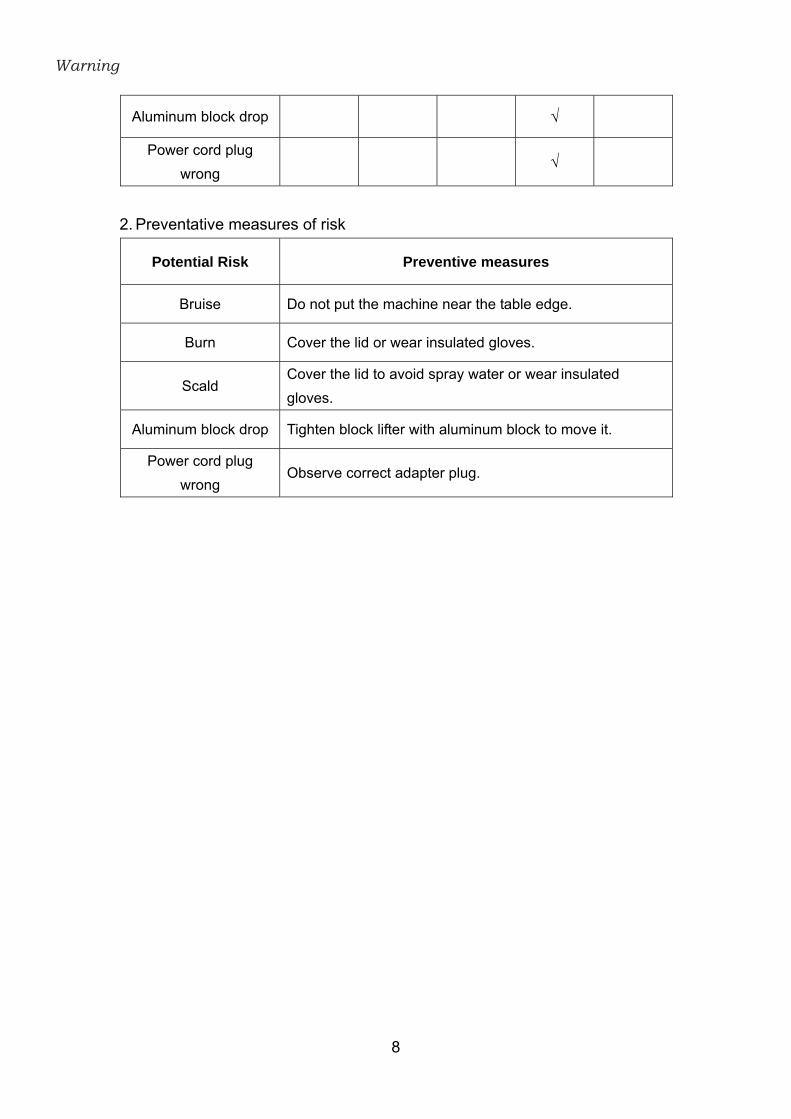
2. Preventative measures of risk
Potential Risk Preventive measures
Bruise Do not put the machine near the table edge.
Burn Cover the lid or wear insulated gloves.
Scald Cover the lid to avoid spray water or wear insulated
gloves.
Aluminum block drop Tighten block lifter with aluminum block to move it.
Power cord plug
wrong Observe correct adapter plug.

Section 1
9
Section 1 Introduction
The mini cooler 200 series is designed to meet the requirement of accurate
temperature control, ease of data transferring and programming, small foot
print and ease of use.
Mini cooler is capable of setting temperature between 100°C to -10°C
depending on your application and usage. The microprocessor controller
helps providing precise heating and cooling control, whether you need a PCR
incubation or enzyme/sample storage, mini-cooler does it all.
The aluminum alloy block for mini cooler provides flexibility and convenience
to share blocks in between mini cooler and mini dry bath.
Experiment-on-the-Go !
It gives you the flexibility to bring your experiments on the go. The 12V
car-adaptor allows you to take your samples wherever you need with peace
of mind on the transferring and transporting between 100°C to -10°C.
Small foot print
Personal lab incubation cooler, only a small lab bench space is needed
Quick start
Preset temperature allows one button operation start
Key features of Mini-cooler 200 series
‐ Small foot-print to fit spaced limited lab bench
‐ Alarm, timer and digital user temperature calibration
‐ Single molded chamber, no cracks or welds
‐ Preset temperature for Quick Start operation
‐ Temperatures programmable operation for sophisticated heating and
cooling protocols
‐ PTFE coated chamber resists to stains and water mark
‐ Can be used as a mini water bath or bead bath

Section 1
10
‐ Astounding heating and cooling rate for different application
‐ Small voltage consumption for low electricity consumption
‐ Variety sizes of aluminum alloy block for selection and customization
‐ USB and Bluetooth port for easy data logging, transfer and modification
‐ Optional car adaptor provides portability on the go
‐ Blocks interchangeable with mini- dry bath

Section 2
11
Section 2 Product Specifications
Display LCD
Maximum Heating / Cooling
Power 60W
Controller High performance Microprocessor
Dimension L152 x W135 x H185mm
Temperature Control Range 30°C below ambient temperature ( minimum -10°C) to
100°C.
Temperature Increment /
Decrement 0.1°C
Temperature Calibration Yes
Temperature Uniformity ±0.2°C @ 37°C
Temperature Accuracy ±0.25°C @ 37°C
Operating Temperature Ambient to 40°C
Heating Rate Max. 5°C / min
Cooling Rate Max. 4°C / min
Heating Parts PI (Polyimide) Film Heater
Cooling Parts TEC (Thermoelectric Cooling)
Programing
a. Constant Mode:
(1)Temperature: 30°C below ambient temperature
(minimum -10°C) to 100°C.
(2)Timer: 1- 9999 minutes.
b. Program Mode:
(1)Programmable: 1-4 steps and up to 9 cycles.
(2)Timer: 1-9999 minutes for each step.
c. Annealing program
d. Quick Start:
(1)Temperature: 4°C / 16°C / 37°C / 56°C / 95°C.
(2)Timer: ∞ for each Temperature.
Timer 1 min. – 9999 min.
Block Type Standard and customized upon request.
Heating / Cooling Chamber
Material Molded aluminum alloy chamber coated with PTFE.
Block Material Aluminum alloy

Section 2
12
Safety Device Leakage proof for heating chamber
Over Temperature protection
Rated Voltages AC input 100V - 240V~; 2A, 50/60 Hz
DC input: +12V / 5A, 60W max.
Weight Approx. 1.3 kg
Feature USB for data logger and control
Lid Transparent Lid
Computer/laptop recommended specification
Processor 1.8GHz Pentium® IV or equivalent AMD Athlon®
processor
Memory 1GB
Storage 1GB available HD space
Media CD-ROM drive
Connectivity 1 port USB 2.0
Display 1280x800 resolutions
Operating System Windows® 7 SP1/ Windows® Vista SP1 /
Windows® XP SP3/ Windows® 8
Microsoft .NET Framework .NET Framework 2.0 or above

Section 3
13
Section 3 Installation Instructions
The Mini cooler Incubator is actually a pre-installed instrument. As long as it is
placed on a sturdy and level surface in a safe, dry place, and is inserted with
one or two heating aluminum block(s) or simply water as a water bath, it is
ready for operation.

Section 4 4.1 Controls and Features
14
Section 4 Device Operation Instructions
4.1 Controls and Features
Please refer to below figures on the following page for the location of the
different keys.
Front panel
Back panel
1. Start / Stop: Active and stop operation of the device.
2. Enter: Enable the alteration of a selected value.
(1)
(2)
(4)
(3) (6)
(5)
(7)
(8)
(9)

Section 4 4.1 Controls and Features
15
3. Up: To increase temperature value or time value.
4. Down: To decrease temperature value or time value.
5. Left: Move cursor to the left. Return to previous step under the
operation mode.
6. Right: Move cursor to the right.
7. AC Power Switch: The main power switch. Press “ ⅼ ” to
switch on the device. Press “○” to switch off the device.
8. AC Power Cord: For AC inlet and fuse holder.
9. B Type USB Port: Connect computer to record data.

Section 4 4.2 Turn On the Instrument
16
4.2 Turn On the Instrument
1. Place Programmable Mini cooler Incubator on a sturdy, level surface in a
safe, dry place away from laboratory traffic.
2. Ensure that the AC power switch is OFF, and then plug the three-pronged
power cord into a grounded three-prong AC outlet of the appropriate voltage.
3. Select a suitable module block or pour appropriate water volume into the
Programmable Mini cooler Incubator.
4. Switch the main power ON.

Section 4 4.3 Setting Calendar
17
4.3 Setting Calendar
1. Please switch the main power ON and press key simultaneously
until the display 1600 (range is: 1500~2000) appeared which is located on
the up left area of display shown as below. And then release them
immediately.
2. The Calendar Setting Screen is displayed. The parameters on the screen
are flashing, and then use key and key to move cursor to
the parameter that you want to changed. Use key and key
to adjust the setting value, then press key to store the updated value.
( Date ) ( Time )

Section 4 4.4 Operation Mode: Quick Start Mode
18
4.4 Operation Mode: Quick Start Mode
1. Switch the main power ON.
2. Use key and key to select “Quick Start” icon, then press
key to enter next screen.
3. There are 5 modes of “Quick Start”. Use key and key to
select the mode that you want, and then press key to store the
upsated value. Those parameters of quick start’s mode are settled by
factory. Press key return to select operation mode page.
4. Press to start heating or cooling.
5. Press again to stop the device. A confirm page will pop out, select
“YES” to leave the mode .

Section 4 4.4 Operation Mode: Quick Start Mode
19
Note (1):
When running Quick Start Mode, the current temperature of block and the step
settings will show on the screen.
The running time works in only one situation - starts counting up once reaching
the set temperature.
Press key to display the set temperature and time. It will be kept on
screen for 5 seconds or just press key again to go back monitor screen immediately.

Section 4 4.5 Operation Mode: Constant Mode
20
4.5 Operation Mode: Constant Mode
1. Switch the main power ON.
2. Use key and key to select “Constant Mode” icon, then
press key to enter next screen.
3. Press key make the parameter become flashing, then use
key and key to move cursor to the parameter. Use key and
key to adjust the setting value, then press key to store the
updated value. Press key return to select operation mode page.
4. Press key make the parameter become flashing, then use
key and key to move cursor to the parameter. Use key and
key to adjust the setting value, then press key to store the
updated value. Press key return to select operation mode page.
Note (1): 0 minutes means infinity.
5. Press to start heating or cooling.
Section 4 4.5 Operation Mode: Constant Mode
21
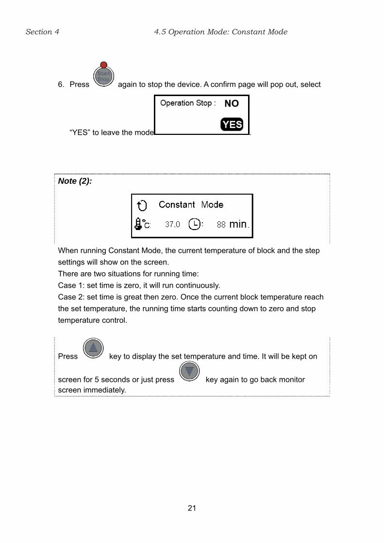
6. Press again to stop the device. A confirm page will pop out, select
“YES” to leave the mode .
Note (2):
When running Constant Mode, the current temperature of block and the step
settings will show on the screen.
There are two situations for running time:
Case 1: set time is zero, it will run continuously.
Case 2: set time is great then zero. Once the current block temperature reach
the set temperature, the running time starts counting down to zero and stop
temperature control.
Press key to display the set temperature and time. It will be kept on
screen for 5 seconds or just press key again to go back monitor screen immediately.

Section 4 4.6 Operation Mode: Programmable Mode
22
4.6 Operation Mode: Programmable Mode
1. Switch the main power ON.
2. Use key and key to select “Programmable Mode” icon,
then press key to enter next screen.
3. Press key and then use key and key to set
program number (It can maximum save 10 file from 0 ~ 9). Press
key again to store the program number. Press key return to select operation mode page.
4. Press key to next screen. There are 4 steps in a program: Step0 –
Step3. Press key to set the temperature and time parameters.
5. Use key and key to move cursor to the parameter. Use
key and key to change the parameter. Press key
again to store the program number. Press key return to select operation mode page.

Section 4 4.6 Operation Mode: Programmable Mode
23
6. Press key to next screen. Repeat operating step 4~6 to set Programmable Mode Step 1-3.
7. Press key and then use key and key to increase or
decrease value for cycle times (up to 9 cycles), then press key to store the updated value.
8. Press key to start the program.
9. Press key again to stop the unit. A confirm page will pop out, select
“YES” to leave the mode .
Note (1): All the step parameters of Programmable Mode will be saved in the device
until the next time you change them.

Section 4 4.6 Operation Mode: Programmable Mode
24
Note (2):
When running Programmable Mode, the current temperature of block and the
step settings will show on the screen.
You can set up all 4 steps, or, for example, if you only need 3 steps (Step0 –
Step2) in the program, set the running time in Step3 at 0 (zero). Then when the
program finishes Step2, it will return to the first step or stop the temperature
control (i.e., gradually return to the ambient temperature), depending on the
numbers of cycles you set. The following charts are examples:
ambient temp.
Programmable Mode (Cycle:1)
The temperature in Step3 can be set at any value. When the running time in one of steps is set at 0, the program will only run the previous steps. And in this example, the running time in Step3 is 0, as a result, the system will recognize only 3 steps in this program.

Section 4 4.6 Operation Mode: Programmable Mode
25
Press key to display the set temperature and time. It will be kept on
screen for 5 seconds or just press key again to go back monitor screen immediately.
Section 4 4.7 Operation Mode: Annealing Program
26
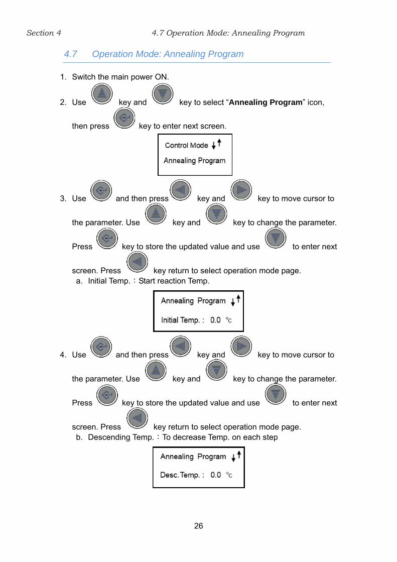
4.7 Operation Mode: Annealing Program
1. Switch the main power ON.
2. Use key and key to select “Annealing Program” icon,
then press key to enter next screen.
3. Use and then press key and key to move cursor to
the parameter. Use key and key to change the parameter.
Press key to store the updated value and use to enter next
screen. Press key return to select operation mode page. a. Initial Temp.:Start reaction Temp.
4. Use and then press key and key to move cursor to
the parameter. Use key and key to change the parameter.
Press key to store the updated value and use to enter next
screen. Press key return to select operation mode page. b. Descending Temp.:To decrease Temp. on each step

Section 4 4.7 Operation Mode: Annealing Program
27
5. Use and then press key and key to move cursor to
the parameter. Use key and key to change the parameter.
Press key to store the updated value and use to enter next
screen. Press key return to select operation mode page. c. Holding Time:Holding time for each step
6. Use and then press key and key to move cursor to
the parameter. Use key and key to change the parameter.
Press key to store the updated value and use to enter next
screen. Press key return to select operation mode page. d. Final Temp.:Temp. for end step
7. Press key to start the program.
8. Press key again to stop the unit. A confirm page will pop out, select
“YES” to leave the mode .

Section 4 4.7 Operation Mode: Annealing Program
28
Note (1):
When running Annealing Program Mode, the current temperature of block and
the step settings will show on the screen
There are two situations for running time:
Case 1: set time is zero. Once the current block temperature reach the
set temperature, it will go to the next step immediately.
Case 2: set time is great then zero. Once the current block temperature reach
the set temperature, the running time starts counting down to zero and stop
temperature control.
Press key to display the set temperature and time. It will be kept on
screen for 5 seconds or just press key again to go back monitor screen immediately.
Note (2): The final step in Annealing Mode step parameters will run
continuously until stop by user.

Section 4 4.8 Operation Mode: Setting Device Number
29
4.8 Operation Mode: Setting Device Number
1. Switch the main power ON.
2. Use key and key to select “Device Number” icon, then
press key make the parameter become flashing. .Use key
and key to change the step parameter then press key to
store the updated value (Device Number range is 1~99).
Section 5 5.1 Install Mini cooler multi-device control software
30
Section 5 Installation Software Instructions
*To start install the program, please log in as an administrator on the
computer.
Please refer to the Web link to change the account of computer:
5.1 Install Mini cooler multi-device control software
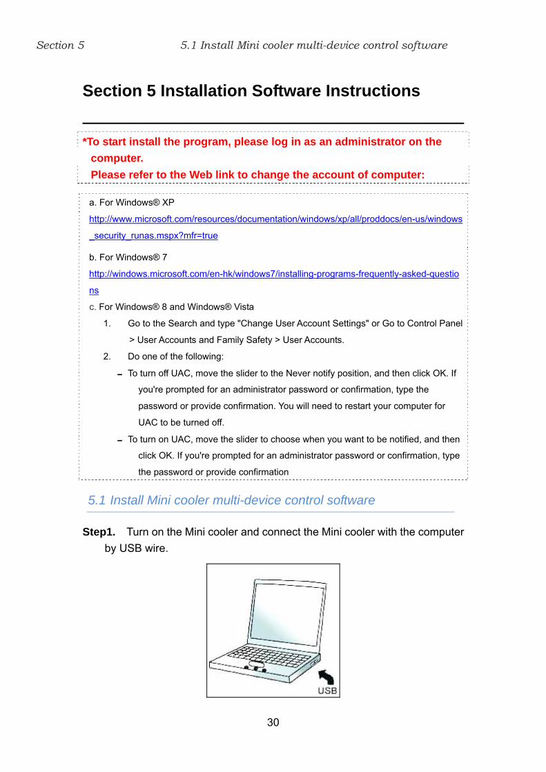
Step1. Turn on the Mini cooler and connect the Mini cooler with the computer
by USB wire.
a. For Windows® XP
http://www.microsoft.com/resources/documentation/windows/xp/all/proddocs/en-us/windows
_security_runas.mspx?mfr=true
b. For Windows® 7
http://windows.microsoft.com/en-hk/windows7/installing-programs-frequently-asked-questio
ns
c. For Windows® 8 and Windows® Vista
1. Go to the Search and type "Change User Account Settings" or Go to Control Panel
> User Accounts and Family Safety > User Accounts.
2. Do one of the following:
To turn off UAC, move the slider to the Never notify position, and then click OK. If
you're prompted for an administrator password or confirmation, type the
password or provide confirmation. You will need to restart your computer for
UAC to be turned off.
To turn on UAC, move the slider to choose when you want to be notified, and then
click OK. If you're prompted for an administrator password or confirmation, type
the password or provide confirmation
Section 5 5.1 Install Mini cooler multi-device control software
31
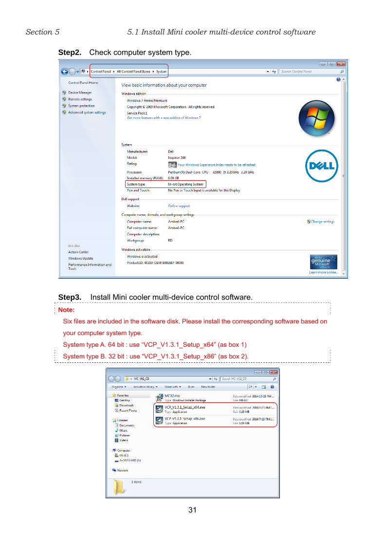
Step2. Check computer system type.
Step3. Install Mini cooler multi-device control software.
Note:
Six files are included in the software disk. Please install the corresponding software based on
your computer system type.
System type A. 64 bit : use “VCP_V1.3.1_Setup_x64” (as box 1)
System type B. 32 bit : use “VCP_V1.3.1_Setup_x86” (as box 2).

Section 5 5.1 Install Mini cooler multi-device control software
32
Step4. Click “next” to start installs the program.
Step5. Click “Next” to start installs the device in order to work program.
Section 5 5.1 Install Mini cooler multi-device control software
33
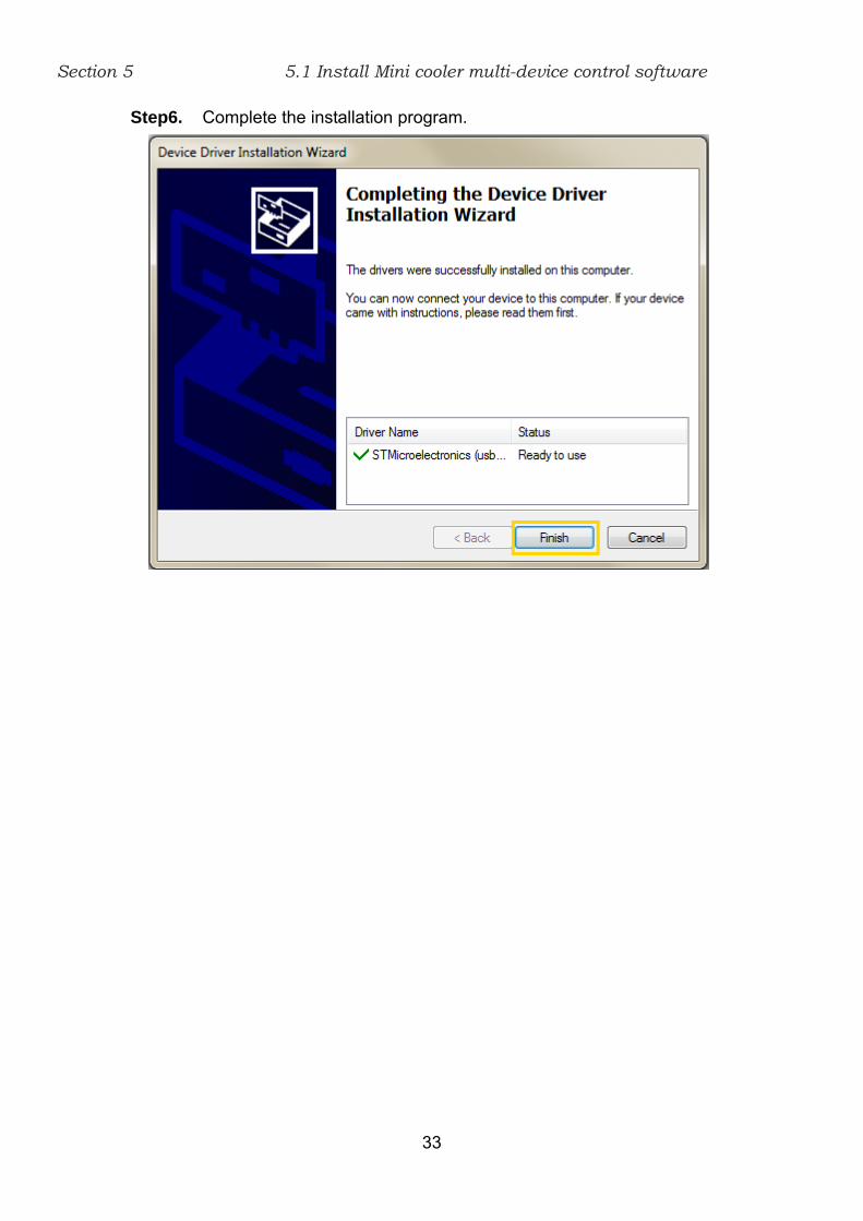
Step6. Complete the installation program.
Section 5 5.2 Install Mini cooler view chart software
34
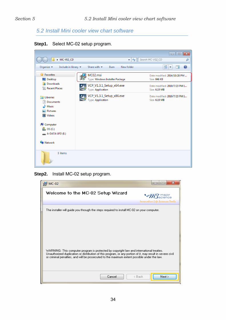
5.2 Install Mini cooler view chart software
Step1. Select MC-02 setup program.
Step2. Install MC-02 setup program.

Section 5 5.2 Install Mini cooler view chart software
35
Step3. Accept the license agreement and then press the “Next” to proceed.
Step4. Save this program in your specifying location then press “Next” to
proceed.

Section 5 5.2 Install Mini cooler view chart software
36
Step5. Click “Next” to begin the installation.
Step6. Press “Close” to complete the program installation.

Section 5 5.2 Install Mini cooler view chart software
37
Step7. The short paths will be shown on desktop. Double click on MC-02
icon to open the software.

Section 6 6.1 Temperature Monitoring Chart
38
Section 6 Function Control Software Instructions
6.1 Temperature Monitoring Chart
System Setup Function
1. Option Setting: Set up the file name format and record
period.
2. ReScan Device: Detect the connection of device.
3. About Information: MC-02 software version and patent
information.
(1)~(4)
(5)~(11) (12)~(26) (27)
Section 6 6.1 Temperature Monitoring Chart
39
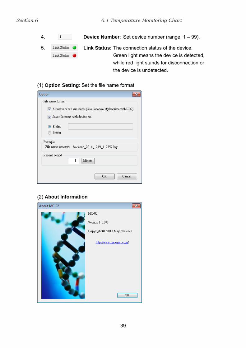
4. Device Number: Set device number (range: 1 – 99).
5.
Link Status: The connection status of the device.
Green light means the device is detected,
while red light stands for disconnection or
the device is undetected.
(1) Option Setting: Set the file name format
(2) About Information

Section 6 6.1 Temperature Monitoring Chart
40
Operation Mode:
6. Quick Start: There are 5 default modes, to select
the mode by scrollbar.
7. Constant Mode: There are setting parameters for
Temp. and Time.
8.
Programmable Mode: From Program 0 to
Program 9, 10 programs for
setting. To select the mode
by scrollbar.
9.
Annealing Program: There are setting parameters
for Initial Temp., Descending
Temp., Holding Time, and
Final Temp.

Section 6 6.1 Temperature Monitoring Chart
41
Run / Stop Function:
10. Run: To start the operation mode.
11. Exit: To exit this software.
Temperature Curve Display
12. Temp. SV curve: The color of temperature set
value curve is white.
13. Temp. PV curve: The color of temperature real
value curve is red.
Temperature / Time Function
14.
The set temperature value.
15.
The real temperature value being measured.
16.
The set time value.
REC. Period
17.
To set up how frequent the operation data is
recorded. Press or bottom, it can
be set either in minute or in second.
Chart Option Function
18.
To set the minimum temperature value on the
chart.

Section 6 6.1 Temperature Monitoring Chart
42
19.
To set the maximum temperature value on the
chart.
20.
To set the minimum time value on the chart.
21.
To set the maximum time value on the chart.
Time Function
22. To show a part of time on the chart.
23. To show the current trend of the temperature.
Data Function
24. To reset all chart option parameters.
25. To apply the changes change the temperature value
and time value by setting.
26. Print out the chart using the printer.
26. Display Screen: This area shows the real-time Temp. – Time curve.

Section 6 6.2 Operation Mode Setting Table
43
6.2 Operation Mode Setting Table
Program Mode
1.
There are 4 setting steps, from step 0 to step 3
for temperature (Temp.) and operation time
(Time) setting, and also setting for Cycle Times.
(1)
(2)~(5) (6)~(7) (8)~(10)

Section 6 6.2 Operation Mode Setting Table
44
Annealing Program
2. To set the initial temperature value.
3.
To set descending temperature value.
4. To set holding time value.
5. To set final temperature value.
Constant Mode
6.
To set the target temperature value of constant
mode.
7.
To set the target time value of constant mode.
Time unit / Upload or Download Data
8.
All set time parameters unit is minute.
9. To upload the parameter in the software to Mini
cooler.
10. To download the setting parameter from Mini cooler to
the software.

Section 6 6.3 View History
45
6.3 View History
Temperature Curve Display
1. Temp. SV curve: The color of temperature set
value curve is white.
2. Temp. PV curve: The color of temperature real
value curve is red.
History Data
3. To view historic record data.
4. To download the historical data from Mini cooler to
computer.
(1)~(14)
(15)

Section 6 6.3 View History
46
Chart Option Function
5.
To set the minimum temperature value on the
chart.
6.
To set the maximum temperature value on the
chart.
7.
To set the minimum time value on the chart.
8.
To set the maximum time value on the chart.
Time Function
9. To show a period of 20 minutes/seconds of the
curve on the chart.
10. To show the whole curve on the chart.
11.
To show a specific period of time of the curve on
the chart. Input the desired minimum time and
maximum time to the chart option.
Data Function
12. To reset all chart option parameters.
13. To change the temperature value and time value by
setting.
14. Print out the chart using the printer.
15. Display Screen: This area shows the historical Temp. – Time curve.
Section 7
47
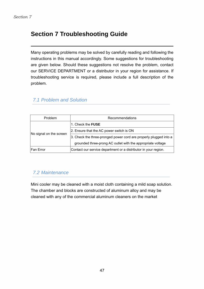
Section 7 Troubleshooting Guide
Many operating problems may be solved by carefully reading and following the
instructions in this manual accordingly. Some suggestions for troubleshooting
are given below. Should these suggestions not resolve the problem, contact
our SERVICE DEPARTMENT or a distributor in your region for assistance. If
troubleshooting service is required, please include a full description of the
problem.
7.1 Problem and Solution
Problem Recommendations
1. Check the FUSE
2. Ensure that the AC power switch is ON No signal on the screen
3. Check the three-pronged power cord are properly plugged into a
grounded three-prong AC outlet with the appropriate voltage
Fan Error Contact our service department or a distributor in your region.
7.2 Maintenance
Mini cooler may be cleaned with a moist cloth containing a mild soap solution.
The chamber and blocks are constructed of aluminum alloy and may be
cleaned with any of the commercial aluminum cleaners on the market

Section 7 7.3 Temperature Calibration
48
7.3 Temperature Calibration
Mini Cooler with the optional block has been calibrated as a set. But, the
different kinds of block, whose T are not the same result different influences.
For optimum accuracy temperature control or while changing with different
kinds of block, Mini Cooler should be calibrated in accordance with the
procedure outlined below.
Note: This has been done in factory.
1. Insert a 300mm calibrated laboratory Thermometer into the Thermometer
holding port on the block.
2. Please switch the main power OFF/ON and press key
simultaneously until the display 1100 (range is: 1000~1500) appeared which
is located on the up left area of display shown as below. And then release
them immediately.
3. The Inner Calibration Screen is displayed. T1 default target temperature is
0℃. The device will start cooling from ambient to 0℃, when temperature
arrival 0℃ and then to start countdown from 30 min to 0 min. The device will
alarm “beep” while T1 0℃ and 0 min. T1 value is flashing, and then
use key and key to enter the real temperature as
thermometer. Press key to store the updated value.

Section 7 7.3 Temperature Calibration
49
(Start calibration) (Arrival the target temperature)
(Key in the same value as thermometer)
4. Use key and key to adjust the T2 value (temperature range
is -5℃ ~ -10℃). The device will start cooling from 0℃ to -5℃, when
temperature arrival -5℃ and then to start countdown from 30 min to 0 min.
The device will alarm “beep” while T1 -5℃ and 0 min. T2 value is flashing,
and then use key and key to enter the real temperature as
thermometer. Press key to store the updated value.
(Set a calibration target temperature) (Start calibration)
(Key in the same value as thermometer) (Arrival the target temperature)
5. Use key and key to adjust the T3 value (temperature range

Section 7 7.3 Temperature Calibration
50
is 37℃ ~ 100℃). The device will start heating from -5℃ to 100℃, when
temperature arrival 100℃ and then to start countdown from 30 min to 0 min.
The device will alarm “beep” while T3 100℃ and 0 min. T3 value is flashing,
and then use key and key to enter the real temperature as
thermometer. Press key to store the updated value.
(Set a calibration target temperature) (Start calibration)
(Key in the same value as thermometer) (Arrival the target temperature)
6. Please wait for few more minutes that microprocessor will auto adjust
temperature until display value is the same as thermometer.

Section 8
51
Section 8 Ordering information
Cat. No. Description
MC-0203 Mini Cooling Dry Bath Incubator, 200 series,
programmable cooling and heating capability, without
block
ACCESSORIES
MD-MINI-B01 For 0.2ml tube(PCR Strip tube), ø 6.35mm, 32 wells,
L71xW47xH32, Depth 19mm
MD-MINI-B02 For 1.5ml tube, ø 10.8mm, 12 wells, L71xW47xH32mm,
Depth 28.5mm
MD-MINI-B03 For 15ml tube, ø 17.3mm, 6 wells, L71xW47xH75mm,
Depth 70mm
MD-MINI-B04 For 50ml tube, ø 29.2mm, 2 wells, L71xW47xH75mm,
Depth 72mm
MD-MINI-B05 For 0.5ml tube, ø 8.0mm, 12 wells, L71xW47xH32mm,
Depth 25mm
MD-MINI-B06 For 2.0ml or 1.5ml tube, ø 11.0mm, 12 wells,
L71xW47xH32mm, Depth 30mm
MD-MINI-B07 For 2.0ml or 1.5ml tube, ø 10.9mm, 12 wells,
L71xW47xH32mm, Depth 30mm
MS-BL95-E Block lifter 95mm, with E-Type Retaining Rings
MD-MINI-CAR-ADAPTER Car Adapter for Mini cooler, 1.5m
MD-MINI-LID MD-MINI Lid, 58.5x83x31.5mm
Note: Customized Aluminum block is also available.
For more detailed Block information, please contact us at [email protected] or
visit our web-site, www.majorsci.com.

Section 9
52
Section 9 Warranty
Major Science warrants apparatus of its manufacture against defects in
materials and workmanship, under normal service, for one year from the
shipping date to purchaser. This warranty excludes damages resulting from
shipping, misuse, carelessness, or neglect. Major Science’s liability under the
warranty is limited to the receipt of reasonable proof by the customer that the
defect is embraced within the terms of the warranty. All claims made under this
warranty must be presented to Major Science within one year following the
date of delivery of the product to the customer.
Manufacturer
Major Science Co., Ltd.
Address:
No. 37, Wuquan 5th Rd.,
Wugu Dist., New Taipei City 24888
Taiwan
T/ 886-2-2298-1055
F/ 886-2-2299-7871
Contact Information
Address
19959 Sea Gull Way
Saratoga, CA 95070
U.S.A
T/ 1-408-366-9866
F/ 1-408-446-1107

53
MEMO

54
MEMO

55
MEMO

56
MEMO