Embed Size (px)
Citation preview

Instruction Sheet Rev. BNo. 412763
ECO 12469
RADIO FREQUENCY SYSTEMSRadio Frequency Systems200 Pondview DriveMeriden, CT 06450Ph (203) 630-3311Fax (203) 634-2272www.rfsworld.com
Install. Instr. for Microwave Parabolic Antennas ∅ 1.8 m (6 ft)
These Installation Instructions are valid for antennas in the following version:
• reflector ∅ 1,8 m (6 ft)• waveguide feed single or dual polarized• pipe mount for installation on ∅115mm• antenna offset to the left or the right• safety collar for easy installation• 2 spindles for fine adjustment azimuth and elevation of ± 5 degrees• 1 sway bar• reflector (Standard)• reflector with shroud, aperture covered by a radome (High-Performance)
Taking into account a slight reduction of the operational windspeed, theantenna can be installed without sway bar if additional fixing points for a swaybar are not available (urban areas).
It is important to mount the antenna exactly as described in these installation instructions.The installed antenna shall be inspected once per year by qualified personnel .RFS disclaims all responsibility for antenna malfunction due to improper or unsafe installation.These installation instructions have been written for qualified, skilled personnel.
We reserve the right to alter details, especially with respect to technical improvement. Page 1 of 13

RADIO FREQUENCY SYSTEMSRadio Frequency Systems200 Pondview DriveMeriden, CT 06450Ph (203) 630-3311Fax (203) 634-2272www.rfsworld.com
∅322 washers 13
AZIMUTH spindle M122 brass nuts M122 spherical washers C132 conical seats D14.2
Azimuth clamp
4 lockwashers
(for left and rightbrackets)
2 washers 13 ∅242 washers 13 ∅372 nuts M122 lockwashers(for lower elevation bracket)Be careful of the postion ofthe 2 different washers. Page 2 of 13
4 screws M12x354 washers 13 ∅244 washers 13 ∅374 nuts M124 lockwashers 3 U bolts 1/2-13 galv.
6 washers 1/2 galv.12 nuts 1/2 galv.
left-bracket
2 screws M20x502 washer 212 spring lock washers A202 nuts M20(for left and right brackets)
4 screws M12x358 washers 13 ∅244 nuts M12
2 washers 13 ∅242 brass nuts M12
Elevationbracket
Right bracket
ELEVATION spindle M162 brass nuts M162 spherical washers C172 conical seats D19
Screw M16x50washer 17spring lock washers A16nut M16
1. Tools required for installation
2. Assembly of the mount
Tools are not included with antenna:• Hoisting device for 2500 N• Shackle• 2 ropes• Water balance and compass• Mallet• Wrenches for hexagon bolts:M5(8), M6(10), M10(17), M12(19), M14(21), M16(24), M20(30)(values in brackets=openings of spanners)• Torque wrench from 5 to 250 Nm• Nail set or punch for ∅6mm.
For easy operation of the bolted joints, « Anti Seize » Installation Paste should be applied toall threads of bolts and fine adjustment spindles except for galvanized u-bolt and hardware. See Page 12.After this, keep the lubricated threads free of dust and dirt!For fastener torque specification, see Page 13.
RADIO FREQUENCY SYSTEMSRadio Frequency Systems200 Pondview DriveMeriden, CT 06450Ph (203) 630-3311Fax (203) 634-2272www.rfsworld.com
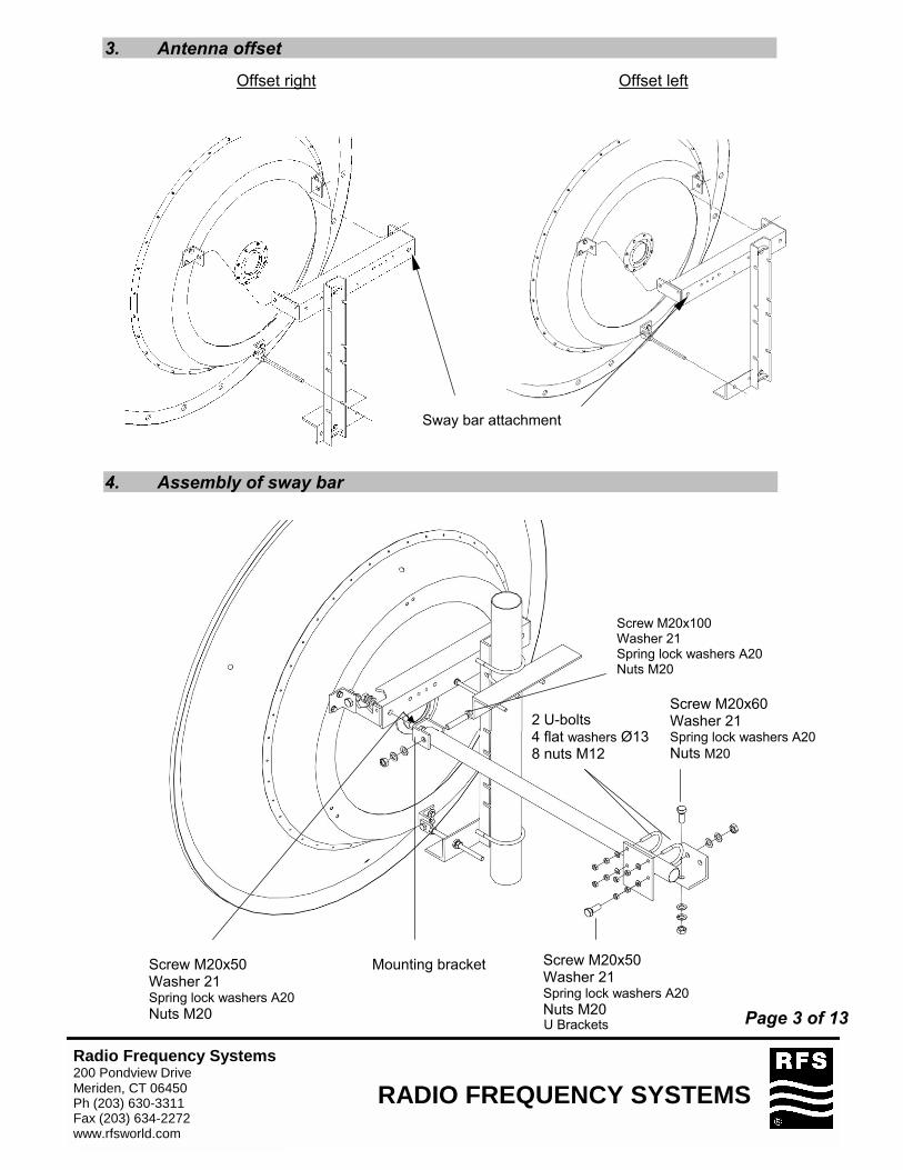
3. Antenna offset
Sway bar attachment
Offset leftOffset right
4. Assembly of sway bar
Screw M20x100Washer 21Spring lock washers A20Nuts M20
2 U-bolts4 flat washers Ø138 nuts M12
Screw M20x50Washer 21Spring lock washers A20Nuts M20
Mounting bracketScrew M20x50Washer 21Spring lock washers A20Nuts M20
Screw M20x60Washer 21Spring lock washers A20Nuts M20
U Brackets Page 3 of 13

RADIO FREQUENCY SYSTEMSRadio Frequency Systems200 Pondview DriveMeriden, CT 06450Ph (203) 630-3311Fax (203) 634-2272www.rfsworld.com
5. Sway bar positioning
2.1 Loosen nut of mounting bracket.2.2 Turn the mounting bracket in the right position.2.3 Angle the sway bar.2.4 After installation, tighten all nuts.
Important: Do not angle the sway bar more than 25 degrees in any direction for tower installation!
max. +25 degrees
2.3
2.2
2.1max. -25 degrees
Page 4 of 13
RADIO FREQUENCY SYSTEMSRadio Frequency Systems200 Pondview DriveMeriden, CT 06450Ph (203) 630-3311Fax (203) 634-2272www.rfsworld.com
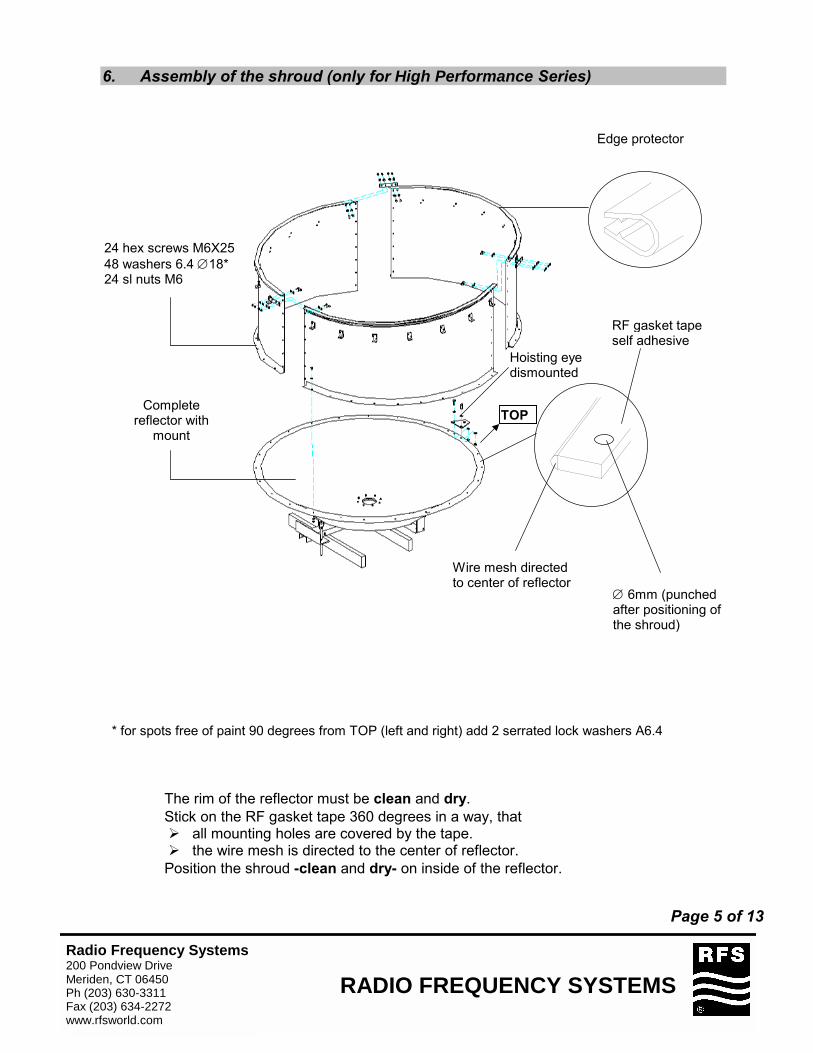
6. Assembly of the shroud (only for High Performance Series)
* for spots free of paint 90 degrees from TOP (left and right) add 2 serrated lock washers A6.4
• The rim of the reflector must be clean and dry.• Stick on the RF gasket tape 360 degrees in a way, that
� all mounting holes are covered by the tape. � the wire mesh is directed to the center of reflector.
• Position the shroud -clean and dry- on inside of the reflector.
Hoisting eye dismounted
Edge protector
24 hex screws M6X2548 washers 6.4 ∅18* 24 sl nuts M6
Complete reflector with
mount
Wire mesh directed to center of reflector
RF gasket tape self adhesive
TOP
∅ 6mm (punched after positioning of the shroud)
Page 5 of 13

RADIO FREQUENCY SYSTEMSRadio Frequency Systems200 Pondview DriveMeriden, CT 06450Ph (203) 630-3311Fax (203) 634-2272www.rfsworld.com
7. Shroud Sections Attachment
8. Feed installation
The feed is a precision component which should be handled with special careduring installation. For instance, always carry the feed, supporting both ends.Any damage may degrade the antenna’s performance. Repair of feeds is notpossible in the field.
4 screws M6X254 sl nuts M68 washers 6.4 ∅18
6* screws M6X166 sl nuts M6 short section12 washers 6.4 ∅18or7* screws M6X167 sl nuts M6 long section14 washers 6.4 ∅18
*7/8 long shroud
Page 6 of 13

RADIO FREQUENCY SYSTEMSRadio Frequency Systems200 Pondview DriveMeriden, CT 06450Ph (203) 630-3311Fax (203) 634-2272www.rfsworld.com
Page 7 of 13
rotatable feed guy ring
• Insert the 3 guy wires in the mounting holes by the rear of the reflector. • Move the feed assembly partway through the connecting ring. • Hook the guy wires into the rotatable guy ring. • Move the feed and fix it in the connecting ring using the 4 screws M5.
• The length "a" of all guy wires must be equal. The maximum spring contraction during thealignment is 5 mm.
8.1. Guy Wire Assemblies

RADIO FREQUENCY SYSTEMSRadio Frequency Systems200 Pondview DriveMeriden, CT 06450Ph (203) 630-3311Fax (203) 634-2272www.rfsworld.com
8.2. Single polarized antennas
Antenna TOP
Vertical Horizontal
8.3. Dual polarized antennas
Antenna TOP
4 screws M54 washers 5.3
clamp brackets with :screws M6spring washers A6.4.
clamp brackets with :screws M6spring washers A6.4.
4 screws M54 washers 5.3
Page 8 of 13

RADIO FREQUENCY SYSTEMSRadio Frequency Systems200 Pondview DriveMeriden, CT 06450Ph (203) 630-3311Fax (203) 634-2272www.rfsworld.com
9. Installation of the planar radome (only High Performance Series)
• Unpack the radome and carefully stretch it over the shroud aperture.• Position the drainhole grommet exactly to the bottom point of antenna, opposite TOP.• Attach J-bolts with springs and smooth radome down as the springs are attached, but do
not displace the edge protector.• Align the length of springs to approximately 135 mm at each J-bolts, this will provide proper
radome tension.10. Hoisting on tower
2 ropes fixed on the mountfor optimal balance Page 9 of 13

RADIO FREQUENCY SYSTEMSRadio Frequency Systems200 Pondview DriveMeriden, CT 06450Ph (203) 630-3311Fax (203) 634-2272www.rfsworld.com
11. Elevation adjustment
Loosen elevation pivots
Loosen nuts and adjust elevation
IMPORTANT : Before adjustments (ELEVATION and AZIMUTH)dismount the sway bar attachment from the tower.
12. Azimuth adjustment
Loosen nuts of the U-bolts
After adjustment fix the sway bar to the tower.
Loosen nuts and adjust azimuth
Important: After azimuth adjustment, lock the first nut on the U-bolts with a torque of95Nm, then the second lock nut is fixed against the first one. Don’t use two wrenches to fixthe second nut. Page 10 of 13

RADIO FREQUENCY SYSTEMSRadio Frequency Systems200 Pondview DriveMeriden, CT 06450Ph (203) 630-3311Fax (203) 634-2272www.rfsworld.com
13. Polarization adjustment
Loosen 4 screws M5 and adjust polarization
Loosen screws M6 and adjust polarization
14. Final Check
When the installation of the antenna has been completed, it is necessary to make sure thatthe installation instructions have been followed in all aspects.It is especially important to check that all bolted joints are tightly locked.
Page 11 of 13

RADIO FREQUENCY SYSTEMSRadio Frequency Systems200 Pondview DriveMeriden, CT 06450Ph (203) 630-3311Fax (203) 634-2272www.rfsworld.com
Installation Paste for Threads
Installation Paste « Anti-seize »
Corrosion preventing and lubricating liquid especially for all threads of stainless steel bolts, U-bolts,spindles.
The installation paste has to be applied to allthreads of bolts and fine adjustment spindles.After this, keep the lubricated threads free of dustand dirt !
Fastener torque specifications are valid for boltswith installation paste only.
Sample: Casting-mount Sample: Steel-mount
Page 12 of 13

RADIO FREQUENCY SYSTEMSRadio Frequency Systems200 Pondview DriveMeriden, CT 06450Ph (203) 630-3311Fax (203) 634-2272www.rfsworld.com
Table of torquesfor nut and bolt connectionsValid for Microwave Parabolic Antennas
Attention: The values in the following table are valid for screws and bolts whichhave been greased according to the installation instructions.
TorquesBolt M5 5 Nm
M6 8 NmM8 17 NmM10 35 NmM12 50 NmM16 140 NmM20/24 240 Nm
U-Bolt M10 20 Nm1/2-13 75 NmM16 124 NmM20 206 Nm
Hexagonal brass nut of fine adjustment M8 5 Nm (Azimuth, Elevation) M10 10 Nm
M12 17 NmM16 50 NmM20 80 NmM24 115 Nm
ExceptionsFixing screw of the fine adjustment (Azimuth) M8x30 8 Nm
M12x55 17 NmU-Bolt for safety collar 4 ft M14 45 NmU-Bolt for safety collar 4 ft M10 12 Nm
Special application : NOT greased
Fixing screw of the plastic radome B4.2 3 Nm
We reserve the right to alter details, especially with respect to technical improvement. Page 13 of 13