Embed Size (px)
Citation preview
Instructions 95-8440PointWatchTM Infrared Hydrocarbon Gas Detector Model PIR9400
8.1 Rev: 12/11 95-8440

Table Of Contents
APPLICATION . . . . . . . . . . . . . . . . . . . . . . . . . . . . . . . . . . . . . . . . . . . . . 1
FEATURES . . . . . . . . . . . . . . . . . . . . . . . . . . . . . . . . . . . . . . . . . . . . . . . 1
SPECIFICATIONS . . . . . . . . . . . . . . . . . . . . . . . . . . . . . . . . . . . . . . . . . . 2
DESCRIPTION . . . . . . . . . . . . . . . . . . . . . . . . . . . . . . . . . . . . . . . . . . . . 5
Detection Method . . . . . . . . . . . . . . . . . . . . . . . . . . . . . . . . . . . . . . . 5
Current Loop Output . . . . . . . . . . . . . . . . . . . . . . . . . . . . . . . . . . . . . 5
Operating Modes . . . . . . . . . . . . . . . . . . . . . . . . . . . . . . . . . . . . . . . 5
INSTALLATION . . . . . . . . . . . . . . . . . . . . . . . . . . . . . . . . . . . . . . . . . . . . 6
Detector Location . . . . . . . . . . . . . . . . . . . . . . . . . . . . . . . . . . . . . . . 6
0 to 100% LFL Linearized Output Options . . . . . . . . . . . . . . . . . . . . 7
PointWatch Termination Boxes (PIRTB) . . . . . . . . . . . . . . . . . . . . . 10
General Wiring Requirements . . . . . . . . . . . . . . . . . . . . . . . . . . . . 10
Detector Wiring Procedure . . . . . . . . . . . . . . . . . . . . . . . . . . . . . . . 11
Detector Separation (Optional) . . . . . . . . . . . . . . . . . . . . . . . . . . . . 13
STARTUP PROCEDURE . . . . . . . . . . . . . . . . . . . . . . . . . . . . . . . . . . . 14
CALIBRATION . . . . . . . . . . . . . . . . . . . . . . . . . . . . . . . . . . . . . . . . . . . . 15
Calibration Equipment . . . . . . . . . . . . . . . . . . . . . . . . . . . . . . . . . . . 15
Calibration Procedures . . . . . . . . . . . . . . . . . . . . . . . . . . . . . . . . . 15
MAINTENANCE . . . . . . . . . . . . . . . . . . . . . . . . . . . . . . . . . . . . . . . . . . 19
Disassembly and Cleaning Procedure . . . . . . . . . . . . . . . . . . . . . . 20
TROUBLESHOOTING . . . . . . . . . . . . . . . . . . . . . . . . . . . . . . . . . . . . . 22
REPLACEMENT PARTS . . . . . . . . . . . . . . . . . . . . . . . . . . . . . . . . . . . . 22
DEVICE REPAIR AND RETURN . . . . . . . . . . . . . . . . . . . . . . . . . . . . . 22
ORDERING INFORMATION . . . . . . . . . . . . . . . . . . . . . . . . . . . . . . . . . 24
APPENDIX A – FM APPROVAL . . . . . . . . . . . . . . . . . . . . . . . . . . . . . . 26
APPENDIX B – CSA APPROVAL . . . . . . . . . . . . . . . . . . . . . . . . . . . . . 27
APPENDIX C – ATEX / CE APPROVAL . . . . . . . . . . . . . . . . . . . . . . . . 28
APPENDIX D – IECEx APPROVAL . . . . . . . . . . . . . . . . . . . . . . . . . . . . 30
APPENDIX E – ADDITIONAL APPROVALS . . . . . . . . . . . . . . . . . . . . . 31

CautionBe sure to read and understand the entire instruction manual before installing or operating the gas detection system. This product is intended to provide early warning of the presence of a flammable or explosive gas mixture. Proper device installation, operation, and maintenance is required to ensure safe and effective operation. If this equipment is used in a manner not specified in this manual, safety protection may be impaired.
APPLICATION
The PointWatchTM Infrared Gas Detector Model PIR9400 is a diffusion-based point-type infrared gas detector. The PointWatch Detector is approved to provide continuous monitoring of methane gas concentration in the range of 0 to 100% LFL. The detector provides a 4-20 mA output signal, corresponding to the detected gas concentration. It has Division and Zone explosion-proof ratings and is suitable for use in indoor and outdoor applications.
The PointWatch Detector Model PIR400 is ideally suited for use in harsh environments and where the cost of required maintenance for conventional catalytic detectors is prohibitive. It will perform reliably in the presence of silicone and other catalytic poisoning agents and can also operate in oxygen free environments or where high background gas levels are present. There are no known poisons that affect this technology.
The PointWatch Detector is globally certified for use in Class 1, Divisions 1 and 2, and Zone 1 hazardous areas. It is also approved as a stand alone gas detector, and complies with global approvals when connected to a stand-alone approved controller for life safety. The approved Det-Tronics controllers are the FlexVu® UD10, Infiniti® U9500, R8471, and Eagle Quantum Premier® (EQP).
FEATURES
• Compliance to ANSI/ISA 12.13.01-2000 performance standard.
• Requires no routine calibration to ensure proper operation.
• Fail-safe operation.
• Continuous self-test automatically indicates a fault or fouled optics condition.
• Unique multi-layered filtering system protects optics from dirt and water ingress.
• Internal heating system minimizes condensation, allowing reliable operation through temperature extremes.
• There are no known poisons, e.g. silicones or hydrides, that compromise the integrity of the measurement.
• Performs well in the presence of high concentrations or constant background levels of hydrocarbons, and in oxygen depleted atmospheres.
• Standard 4–20 mA output (current source).
• Compact, lightweight, explosion-proof housing is designed for duty in harsh environments.
• Standard 0 to 100% LFL detection range.
8.1 ©Detector Electronics Corporation 2011 Rev: 12/11 95-8440
INSTRUCTIONS
PointWatchTM Infrared
Hydrocarbon Gas Detector
Model PIR9400
2 95-84408.1
SPECIFICATIONS
INPUT VOLTAGE—+24 Vdc nominal (range +18 to +30 Vdc).
POWER CONSUMPTION (Watts)—Input Voltage: 18 Vdc 24 Vdc 30 Vdc
Nominal 3.5 4.6 6.2Maximum 4.0 5.5 7.0
DETECTION RANGE—0 to 100% LFL.
GASES —The Model PIR9400 detector is approved to Methane, but most flammable hydrocarbon vapors (ethane, ethylene, propane, butane, and propylene) are also detectable.
Methane gas detection is the factory default gas type setting. Reference the “IR Module Removal and Gas Selection” section of this manual for alternate gas type settings.
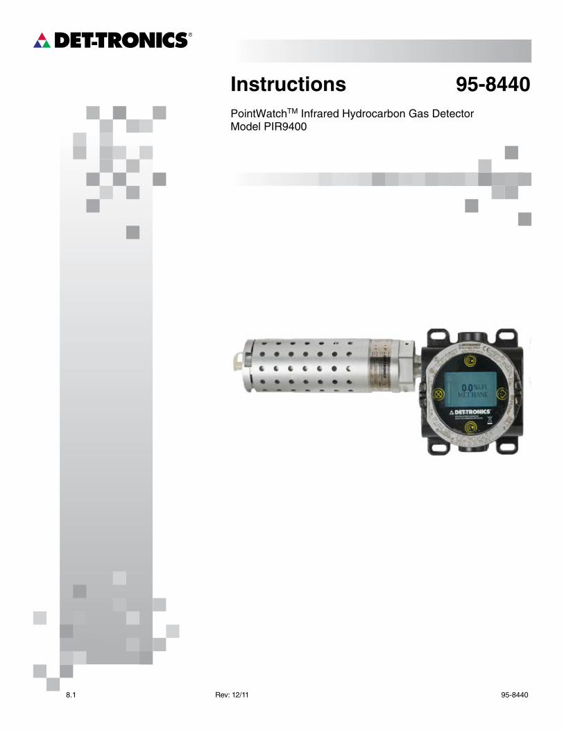
CURRENT OUTPUT (NON-ISOLATED)—Linear 0–20 mA current source.
•4–20 mA output indicates 0 to 100% LFL detection range (for linearized gases)
• 23.2 mA indicates over-range condition•0–2.4 mA levels indicate calibration, fault and
fouled optics conditions.
Refer to Table 1 for a detailed description of current outputs.
Maximum loop resistance: 580 ohms at +24 Vdc. See Figure 1 for further information.
NOTEThe following specifications for Accuracy, Stability and Repeatability are based on 0 to 100% LFL methane.
ACCURACY (Room Temperature)—±3% LFL from 0 to 50% LFL, ±5% LFL from 51% to 100% LFL.
RESPONSE TIME (Seconds)— T50 T90Multilayered aluminum weather baffle With hydrophobic filter 7 14.4 Without hydrophobic filter 5 10
Polyphthalamide (PPA) weather baffle With hydrophobic filter 6 16 Without hydrophobic filter 2 3
STABILITY—Temperature Zero: ±2% LFL from
–40°F to +167°F (–40°C to +75°C)
Span: ±5% LFL at 50% LFL from –13°F to +167°F (–25°C to +75°C)
±10% LFL at 50% LFL from –40°F to –13°F (–40°C to –25°C).
Time (10 months) ±2% LFL (Det-Tronics verified).
REPEATABILITY (Room Temperature)—Zero: ±1% LFLSpan: ±2% LFL at 50% LFL(Det-Tronics verified).
C1964
18 20 22 24POWER SUPPLY VOLTAGE (VDC)
26 28 30 32
MA
XIM
UM
LO
OP
RE
SIS
TA
NC
E (
OH
MS
)
400
500
600
700
800
900
LOOP RESISTANCE (OHMS)
Figure 1—4 to 20 mA Current Loop Resistance
Table 1—Current Loop Output Levels and Corresponding Status Indications
Current Level Status23.2 mA Over-range20.0 mA Full scale (100% LFL)4.0 mA Zero gas level (0% LFL)2.2 mA Zero calibration in progress2.0 mA Span calibration in progress1.8 mA Calibration complete - remove gas1.6 mA Calibration fault1.0 mA Fouled optics0.8 mA 24 Vdc line low (less than 17.5 Vdc)
0.6 mA Calibrate input active at power-up(probable wiring fault)
0.4 mA Active channel fault0.2 mA Reference channel fault0.0 mA CPU system fault, warmup
3 95-84408.1
WIRING—The PointWatch Detector has five 22 AWG wires, 20 inches long for wiring into a termination box, FlexVu UD10 or the Infiniti U9500.
Red = + 24 Vdc Black = – (common) White = 4–20 mA signal output Yellow = Calibration input Green = Chassis ground
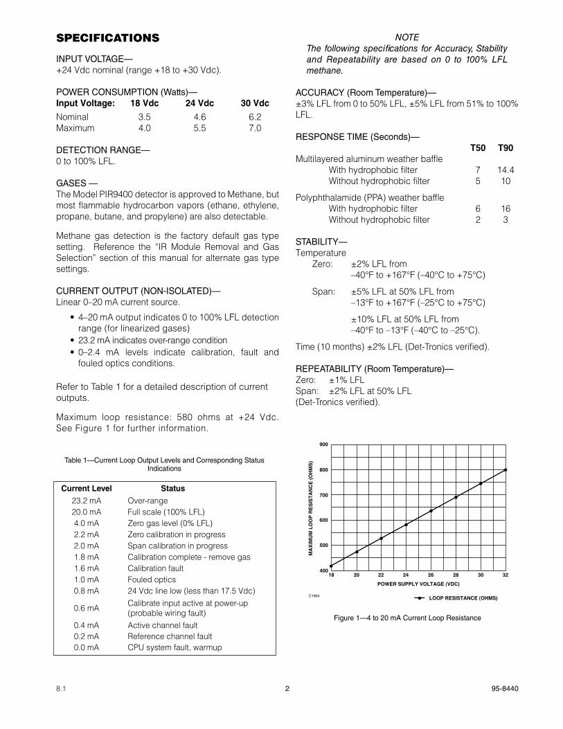
Power Wiring: 18 AWG minimum is recommended for power wiring. Larger diameter wire may be required to maintain a minimum of 18 Vdc (including ripple) at the sensor for all operating conditions (see Figure 2). For maximum EMI/RFI protection, shielded cable is recommended.
OPERATING TEMPERATURE RANGE— –40°F to +167°F (–40°C to +75°C).
STORAGE TEMPERATURE RANGE— –67°F to +185°F (–55°C to +85°C).
HUMIDITY (Non-Condensing)—0 to 99% relative humidity (Det-Tronics verified) 5 to 95% relative humidity (FM/CSA verified).
RFI/EMI PROTECTION—Operates properly with 5 watt walkie talkie keyed at 1 meter.
INGRESS PROTECTION—IP66.
ENCLOSURE MATERIALS—Aluminum (clear anodized) enclosure and weather protection baffles. Content: 0.8% to 1.2% Mg, 0.15% to 0.40% CU.
Stainless Steel (316 electropolished) enclosure, polyphthalamide (PPA) weather protection baffle.
DIMENSIONS—See Figures 3 and 4 for the dimensions of the PointWatch Detector.
CERTIFICATION—
For complete approval details for the PointWatch Detector Model PIR9400 and the PointWatch Termination Box Model PIRTB, refer to the appropriate Appendix:
Appendix A - FMAppendix B - CSAAppendix C - ATEX/CEAppendix D - IECExAppendix E - Additional approvals
WaRninGAlways ensure that the detector/termination box hazardous (classified) location ratings are applicable for the intended use.
C1962
18 20 22 24
POWER SUPPLY VOLTAGE (VDC)
26 28 30 32
MA
XIM
UM
DIS
TA
NC
E F
RO
M P
OW
ER
SU
PP
LY
TO
PO
INT
WA
TC
H IN
FE
ET
16 AWG14 AWG12 AWG 18 AWG
500
1000
1500
2000
2500
0
Figure 2—PIR9400 Wiring Requirements
FMAPPROVED
®
4 95-84408.1
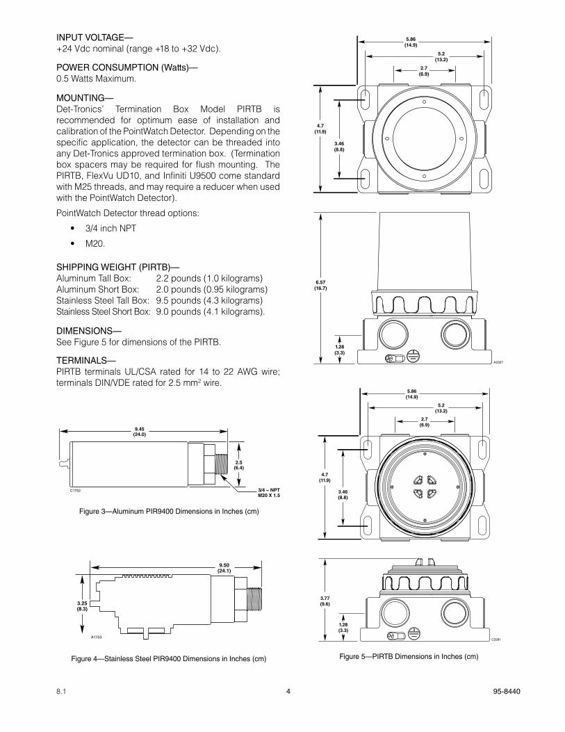
INPUT VOLTAGE—+24 Vdc nominal (range +18 to +32 Vdc).
POWER CONSUMPTION (Watts)—0.5 Watts Maximum.
MOUNTING—Det-Tronics’ Termination Box Model PIRTB is recommended for optimum ease of installation and calibration of the PointWatch Detector. Depending on the specific application, the detector can be threaded into any Det-Tronics approved termination box. (Termination box spacers may be required for flush mounting. The PIRTB, FlexVu UD10, and Infiniti U9500 come standard with M25 threads, and may require a reducer when used with the PointWatch Detector).
PointWatch Detector thread options:
• 3/4 inch NPT
• M20.
SHIPPING WEIGHT (PIRTB)—Aluminum Tall Box: 2.2 pounds (1.0 kilograms)Aluminum Short Box: 2.0 pounds (0.95 kilograms)Stainless Steel Tall Box: 9.5 pounds (4.3 kilograms)Stainless Steel Short Box: 9.0 pounds (4.1 kilograms).
DIMENSIONS—See Figure 5 for dimensions of the PIRTB.
TERMINALS—PIRTB terminals UL/CSA rated for 14 to 22 AWG wire; terminals DIN/VDE rated for 2.5 mm2 wire.
Figure 5—PIRTB Dimensions in Inches (cm)
3.46(8.8)
4.7(11.9)
2.7(6.9)
5.2(13.2)
5.86(14.9)
6.57(16.7)
1.28(3.3)
A2307
3.77(9.6)
1.28(3.3)
3.46(8.8)
4.7(11.9)
2.7(6.9)
5.2(13.2)
5.86(14.9)
C2281
C1752
9.45(24.0)
2.5(6.4)
3/4 – NPTM20 X 1.5
Figure 3—Aluminum PIR9400 Dimensions in Inches (cm)
A1753
9.50(24.1)
3.25(8.3)
Figure 4—Stainless Steel PIR9400 Dimensions in Inches (cm)
5 95-84408.1
DESCRIPTION
DETECTION METhOD
The PointWatch Model PIR9400 operates on the infrared absorption principle. A beam of modulated light is projected from an internal infrared source to a reflector, which sends it back to a pair of infrared sensors. One of the sensors is designated reference and the other active, with different optical filters in front of the two sensors to make them selective to different infrared wavelengths. The reference wavelength is unaffected by combustible gases, while the active wavelength is absorbed by combustible gases. The ratio of the active to the reference wavelength is computed within the detector to determine the concentration of gas present. This value is then converted into a 4–20 mA current output for connection to external display and control systems.
CURRENT LOOp OUTpUT
During normal operation, the Model PIR9400 detector has a current output from 4–20 mA that is proportional to gas concentrations from 0 to 100% LFL. A current output other than 4–20 mA indicates either negative gas level, a fault or over-range condition, or that the detector is in the calibrate mode as indicated in Table 1.
OpERaTINg MODES
Warmup
When power is applied to the detector, it enters a Warmup mode (for approximately one minute) in which it performs diagnostic checks and allows the sensors to stabilize before beginning normal operation. The current output during this period is 0 mA. At the end of the warmup period with no faults present, the detector automatically enters the Normal operating mode. If a fault is present after the warmup, the detector current output will indicate a fault.
Normal
In the normal operating mode, the 4–20 mA signal level corresponds to the detected gas concentration. The detector continuously checks for system faults or initiation of calibration, and automatically changes to the appropriate mode.
Fault
Faults detected during warmup, normal operation, or calibration are indicated by the current loop output as shown in Table 1.
Calibration
All PointWatch Detectors are calibrated at the factory with 50% LFL methane at 2.5% by volume, and are shipped with the internal gas selection switch set for methane gas detection. For additional information on calibration for other gases, refer to the “Linearized Output Options” section of this manual.
Whenever calibration of the PointWatch Detector is required, a momentary connection of the calibration lead wire to DC negative (common) of the power supply initiates the zero and span calibration sequence.
NOTEIt is not recommended to physically connect or touch the calibration lead wire to DC common in the field to begin calibration. This practice is often less than precise, and may result in a spark or other undesirable result. For optimum ease of installation and calibration, always use a PIRTB (furnished with magnetic reed switch, indicating LEDs, and terminal strip), available from Det-Tronics.
The factory default setting for the output current during calibration is an inhibited state. See Table 1 for specific information. Note that a live current output during calibration can also be programmed, although this is not usually recommended. Refer to the “Calibration” section of this manual for details.
The calibration sequence for a particular Model PIR9400 detector installation is typically determined by the type of termination box installed with the detector:
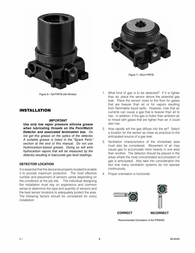
• For non-intrusive one-person calibration, select the PIRTB with Tall Cover. This termination box includes a magnetic reed calibration switch and calibration LED (visible through a viewing window on the cover). By activating the magnetic reed switch with a calibration magnet and then viewing the LED through the window, a one person, non-intrusive calibration can be performed. See Figure 6.
• For intrusive or two-person calibration, select the PIRTB with Short Cover. This termination box typically requires removal of the termination box cover to view the calibration LED, or it requires two people to accomplish a remotely initiated non-intrusive calibration. The short cover termination box includes a magnetic reed calibration switch, calibration LED and a solid cover (no viewing window). This termination box can also be used for sensor separation. See Figure 7.
6 95-84408.1
INSTALLATION
iMPoRtantuse only low vapor pressure silicone grease when lubricating threads on the PointWatch Detector and associated termination box. Do not get this grease on the optics of the detector. A suitable grease is listed in the “Spare Parts” section at the end of this manual. Do not use Hydrocarbon-based grease. Doing so will emit hydrocarbon vapors that will be measured by the detector, resulting in inaccurate gas level readings.
DETECTOR LOCaTION
It is essential that the device be properly located to enable it to provide maximum protection. The most effective number and placement of sensors varies depending on the conditions at the job site. The individual designing the installation must rely on experience and common sense to determine the type and quantity of sensors and the best sensor locations to adequately protect the area. The following factors should be considered for every installation:
1. What kind of gas is to be detected? If it is lighter than air, place the sensor above the potential gas leak. Place the sensor close to the floor for gases that are heavier than air or for vapors resulting from flammable liquid spills. However, note that air currents can cause a gas that is heavier than air to rise. In addition, if the gas is hotter than ambient air or mixed with gases that are lighter than air, it could also rise.
2. How rapidly will the gas diffuse into the air? Select a location for the sensor as close as practical to the anticipated source of a gas leak.
3. Ventilation characteristics of the immediate area must also be considered. Movement of air may cause gas to accumulate more heavily in one area than another. The detector should be placed in the areas where the most concentrated accumulation of gas is anticipated. Also take into consideration the fact that many ventilation systems do not operate continuously.
4. Proper orientation is horizontal.
Figure 6—Tall PIRTB with Window
Figure 7—Short PIRTB
Recommended Orientation of the PIR9400
CORRECT INCORRECT

7 95-84408.1
5. The sensor should be accessible for maintenance.
6. Excessive heat or vibration can result in premature failure of any electronic device and should be avoided if possible.
NOTEFor additional information on determining the quantity and placement of gas detectors in a specific application, refer to the article titled “The Use of Combustible Detectors in Protecting Facilities from Flammable Hazards” contained in the Instrument Society of America (ISA) Transaction, Volume 20, Number 2.
0 TO 100% LFL LINEaRIzED OUTpUT OpTIONS
The PointWatch IR Detector is provided with five field selectable “standard gas” signal processing program settings. These settings create a linearized scale for methane and other gases like ethane, propane, butane, ethylene, or propylene, and are defined as linearized PointWatch gas measurement outputs. This means that the detector is capable of providing an analog signal output that is directly proportional to the % LFL concentration for these gases, provided the proper gas setting has been selected, and the it has been calibrated with the proper calibration gas type.
The PointWatch Detector is factory configured for 0 to 100% LFL methane. To re-configure the detector for one of the other gases, remove the electronic module from the housing and select the desired gas by changing the setting on the rotary gas selection switch. (Refer to “Changing Linearized Output Gas Selection.”) The detector must then be calibrated using a 50% LFL mixture of the selected gas.
NOTEFailure to calibrate the device with a 50% LFL mixture of the selected gas will result in a sensor fault and improper operation of the detector.
Response of Methane-Calibrated pointWatch Detector (Factory Setting) to Other gases
Figure 8 shows the signal output of a PIR9400 that has been properly calibrated for methane in response to other gases. This data should be used as a reference only. It is recommended to always calibrate the detector with the type of gas to be detected.
pointWatch Model pIR9400 Transfer Curves
The gas detector, when set for methane, provides detection of other hydorcarbon vapors at higher LFL readings (see Figure 8). In addition to the standard gases previously mentioned, the PointWatch Detector is capable of detecting and measuring many other hydrocarbon gases and vapors. Although linear detector outputs are not offered for most of these gases, an accurate gas concentration measurement can be made by using a cross-reference data sheet known as a “transfer curve.” (Available upon request.) The transfer curve data sheet is always based upon the following:
1. The data applies to one specific gas/vapor type only.
2. The data is collected at a specific test temperature. (Significant differences in ambient hazard area temperature as compared to test temperature may impact transfer curve accuracy.)
3. The data compares actual hazardous gas concentration in %LFL to the detector signal output level, using all five standard gas settings.
The transfer curve data is then used:
1. To select the optimum detector standard gas setting.
2. To select the appropriate setpoint levels for proper alarm relay actuation. This will ensure that external alarm response action occurs as required.
00 10 20 30 40 50 60 70 80 90 100 110
10
20
30
40
50
60
70
80
90
100
110
%LFL GAS
RESPONSE OF METHANE CALIBRATED POINTWATCH TO OTHER GASES
PO
INT
WA
TC
H O
UT
PU
T (
% L
FL
)
ETHANE
PROPANE
ETHYLENE
PROPYLENE
C2019
Figure 8—Response of Methane-CalibratedPIR9400 (Factory Setting) to Other Gases, at
Tamb = 25°C
8 95-84408.1
It is important to note that whenever using transfer curve data, the Model PIR9400 analog signal output and any real-time visual display of that output (such as a digital display or bar graph) will be offset by a value indicated by the transfer curve data, and therefore must be externally correlated by the viewer.
The transfer curve data sheet for the gas of interest includes five different curves — one for each standard linearized output setting. To select the appropriate setting for the detector, find the curve that:
1. Provides the closest signal correlation across the desired gas measurement range, and
2. Ensures that the offset in the PIR9400 signal output versus gas concentration is an over-reading, as opposed to an unsafe under-reading.
Ideally, at 50% of full scale PIR9400 output (12 ma signal level) the detected gas level will equal 50% LFL gas concentration, and this relationship will remain proportional throughout the gas measurement range. In reality, however, transfer curve data is non-linear, and will result in varying offset levels from proportional linearity throughout the gas measurement range. Refer to the example in Figure 9.
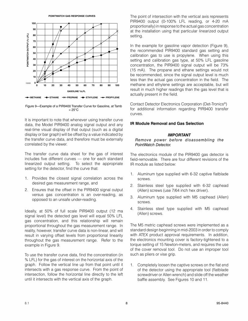
To use the transfer curve data, find the concentration (in % LFL) for the gas of interest on the horizontal axis of the graph. Follow the vertical line up from that point until it intersects with a gas response curve. From the point of intersection, follow the horizontal line directly to the left until it intersects with the vertical axis of the graph.
The point of intersection with the vertical axis represents PIR9400 output (0-100% LFL reading, or 4-20 mA proportionally) in response to the actual gas concentration at the installation using that particular linearized output setting.
In the example for gasoline vapor detection (Figure 9), the recommended PIR9400 standard gas setting and calibration gas to use is propylene. When using this setting and calibration gas type, at 50% LFL gasoline concentration, the PIR9400 signal output will be 73% (15 mA). The propane and ethane settings would not be recommended, since the signal output level is much less than the actual gas concentration in the field. The methane and ethylene settings are acceptable, but will result in much higher readings than the gas level that is actually present in the field.
Contact Detector Electronics Corporation (Det-Tronics®)for additional information regarding PIR9400 transfer curves.
IR Module Removal and gas Selection
iMPoRtantRemove power before disassembling the PointWatch Detector.
The electronics module of the PIR9400 gas detector is field-removable. There are four different revisions of the IR module as listed below:
1. Aluminum type supplied with 6-32 captive flatblade screws.
2. Stainless steel type supplied with 6-32 caphead (Allen) screws (use 7/64 inch hex driver).
3. Aluminum type supplied with M5 caphead (Allen) screws.
4. Stainless steel type supplied with M5 caphead (Allen) screws.
The M5 metric caphead screws were implemented as a standard design beginning in mid-2003 in order to comply with ATEX product approval requirements. In addition, the electronics mounting cover is factory-tightened to a torque setting of 15 Newton-meters, and requires the use of the cover removal tool. Do not use an improper tool such as pliers or vise grip.
1. Completely loosen the captive screws on the flat end of the detector using the appropriate tool (flatblade screwdriver or Allen wrench) and slide off the weather baffle assembly. See Figures 10 and 11.
ETHANE PROPANE ETHYLENE PROPYLENEMETHANE
00 10 20 30 40 50 60 70 80 90 100
10
20
30
40
50
60
70
80
90
100
GASOLINE %LFL
POINTWATCH GAS RESPONSE CURVES
PO
INT
WA
TC
H O
UT
PU
T (
% L
FL
)
C2020
Figure 9—Example of a PIR9400 Transfer Curve for Gasoline, at Tamb = 25°C
9 95-84408.1
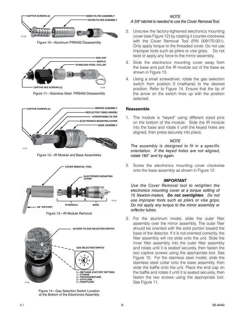
NOTEA 3/8” ratchet is needed to use the Cover Removal Tool.
2. Unscrew the factory-tightened electronics mounting cover (see Figure 12) by rotating it counter-clockwise with the Cover Removal Tool (P/N 009170-001). Only apply torque to the threaded cover. Do not use improper tools such as pliers or vise grips. Do not twist or apply any force to the mirror assembly.
3. Slide the electronics mounting cover away from the base and pull the IR module out of the base as shown in Figure 13.
4. Using a small screwdriver, rotate the gas selection switch from position 0 (methane) to the desired position. Refer to Figure 14. Ensure that the tip of the arrow on the switch lines up with the position selected.
Reassemble
1. The module is “keyed” using different sized pins on the bottom of the module. Slide the IR module into the base and rotate it until the keyed holes are aligned, then press securely into place.
NOTEThe assembly is designed to fit in a specific orientation. If the keyed holes are not aligned, rotate 180° and try again.
2. Screw the electronics mounting cover clockwise onto the base assembly as shown in Figure 12.
iMPoRtantUse the Cover Removal tool to retighten the electronics mounting cover at a torque setting of 15 Newton-meters. Do not overtighten. Do not use improper tools such as pliers or vise grips. Do not apply any torque to the mirror assembly or reflector tubes.
3. For the aluminum model, slide the outer filter assembly over the mirror assembly. The outer filter should be oriented with the solid portion toward the base of the detector. If it is not oriented correctly, the filter assembly will not slide onto the unit. Slide the inner filter assembly into the outer filter assembly and rotate until it is seated securely, then fasten the two captive screws using the appropriate tool. See Figure 10. For the stainless steel model, slide the stainless steel collar onto the base assembly, then slide the baffle onto the unit. Place the end cap on the baffle and rotate it until it is seated securely, then fasten the two screws using the appropriate tool. See Figure 11.
STAINLESS STEEL COLLARBAFFLE
END CAP
CAPTIVE HEX SCREWS (2) A1739
Figure 11—Stainless Steel PIR9400 Disassembly
OUTER FILTER ASSEMBLY
INNER FILTER ASSEMBLYCAPTIVE SCREWS (2)
A1738
Figure 10—Aluminum PIR9400 Disassembly
BASE ASSEMBLY
ELECTRONICS MOUNTING COVER
HYDROPHOBIC FILTER
REFLECTOR TUBES (INSIDE)
MIRROR ASSEMBLYCAPTIVE SCREWS (2)
C1741
Figure 12—IR Module and Base Assemblies
ELECTRONICS MOUNTING COVER
IR MODULE BASE
COVER REMOVAL TOOL
3/8” RATCHET
B1742
Figure 13—IR Module Removal
ACCESS TO GAS SELECTION SWITCH
GAS SELECTION SWITCH
0 = METHANE (FACTORY SETTING)1 = ETHANE2 = PROPANE/BUTANE3 = ETHYLENE4 = PROPYLENEA1740
2
4
6
0
3
57
1
Figure 14—Gas Selection Switch Location at the Bottom of the Electronics Assembly
10 95-84408.1
NOTEAll baffle retainer screws are to be tightened to a torque setting of 5 Newton-meters.
4. Calibrate the detector using a 50% LFL mixture of the gas type that was selected with the gas selection switch. Refer to the “Calibration” section of this manual for complete calibration details.
pOINTWaTCh TERMINaTION BOxES (pIRTB)
Two termination box types for use specifically with the PointWatch Detector are available from Det-Tronics.
• Tall Cover/Window Termination Box for one person, non-intrusive calibration. This termination box includes a magnetic reed calibration switch, calibration LED and a windowed cover. Activating the magnetic reed switch with the calibration magnet and viewing the LED through the window provides one person, non-intrusive calibration capability. See Figure 6.
• Short Cover Termination Box for Model PIR9400 requires two people to accomplish non-intrusive calibration. This termination box includes a magnetic reed calibration switch, calibration LED and a solid cover. Activating the magnetic reed calibration switch with the calibration magnet or touching the calibration lead to the negative lead (common) of the power supply using an external switch are methods used to initiate calibration. This termination box can also be used for sensor separation. See Figure 7.
The PointWatch Detector is designed to be threaded into a termination box, which can be mounted to a solid, vibration free wall or post. A 3/8 inch spacer may be required between the enclosure and the mounting surface to allow adequate room for the sensor and calibration accessory.
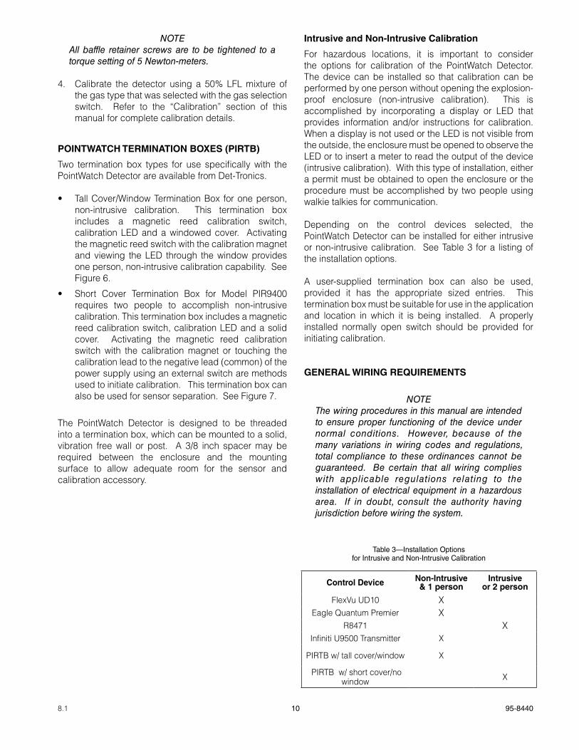
Intrusive and Non-Intrusive Calibration
For hazardous locations, it is important to consider the options for calibration of the PointWatch Detector. The device can be installed so that calibration can be performed by one person without opening the explosion-proof enclosure (non-intrusive calibration). This is accomplished by incorporating a display or LED that provides information and/or instructions for calibration. When a display is not used or the LED is not visible from the outside, the enclosure must be opened to observe the LED or to insert a meter to read the output of the device (intrusive calibration). With this type of installation, either a permit must be obtained to open the enclosure or the procedure must be accomplished by two people using walkie talkies for communication.
Depending on the control devices selected, the PointWatch Detector can be installed for either intrusive or non-intrusive calibration. See Table 3 for a listing of the installation options.
A user-supplied termination box can also be used, provided it has the appropriate sized entries. This termination box must be suitable for use in the application and location in which it is being installed. A properly installed normally open switch should be provided for initiating calibration.
gENERaL WIRINg REqUIREMENTS
NOTEThe wiring procedures in this manual are intended to ensure proper functioning of the device under normal conditions. However, because of the many variations in wiring codes and regulations, total compliance to these ordinances cannot be guaranteed. Be certain that all wiring complies with applicable regulations relating to the installation of electrical equipment in a hazardous area. If in doubt, consult the authority having jurisdiction before wiring the system.
Table 3—Installation Optionsfor Intrusive and Non-Intrusive Calibration
Control Device Non-Intrusive& 1 person
Intrusiveor 2 person
FlexVu UD10 XEagle Quantum Premier X
R8471 XInfiniti U9500 Transmitter X
PIRTB w/ tall cover/window X
PIRTB w/ short cover/no window X
11 95-84408.1
The use of shielded cable in conduit or shielded armored cable is recommended for optimum RFI/EMI protection. In applications where the wiring cable is installed in conduit, the conduit must not be used for wiring to other electrical equipment. To assure proper operation of the detector, the resistance of the connecting wire must be within the specified limits. The maximum distance between the detector and power source is determined by the power supply capability and wire size. See Figure 2 to determine the proper wire size and maximum wiring distance allowed.
It is important that moisture not be allowed to come in contact with the electrical connections of the system.
The use of proper piping techniques, breathers, glands, and seals are required to prevent water ingress and/or maintain the explosion-proof rating.
DETECTOR WIRINg pROCEDURE
iMPoRtantDo not apply power until the wiring procedure is complete and has been verified.
1. Determine the best mounting location for the detector (refer to the “Detector Location” section above). If it is determined that sensor separation is required, see the following section for details.
2. The termination box should be electrically connected to earth ground.
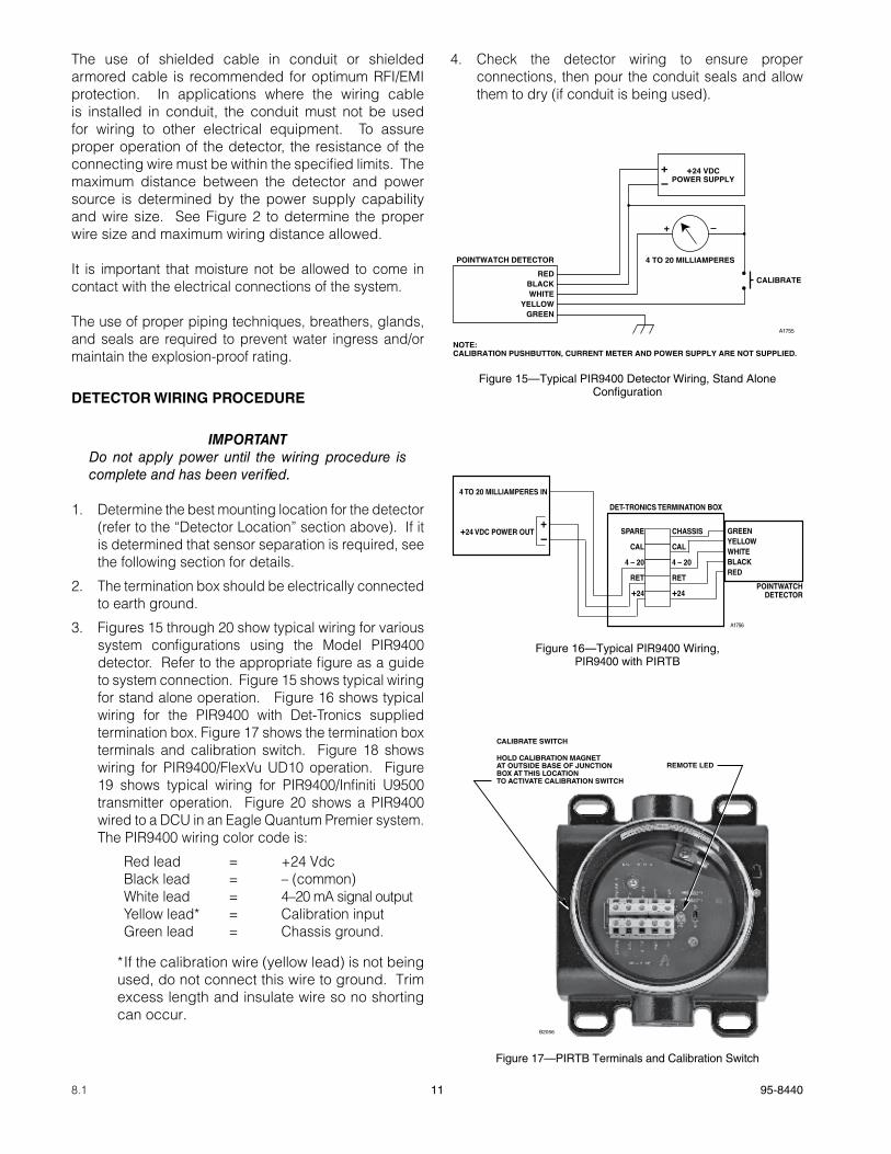
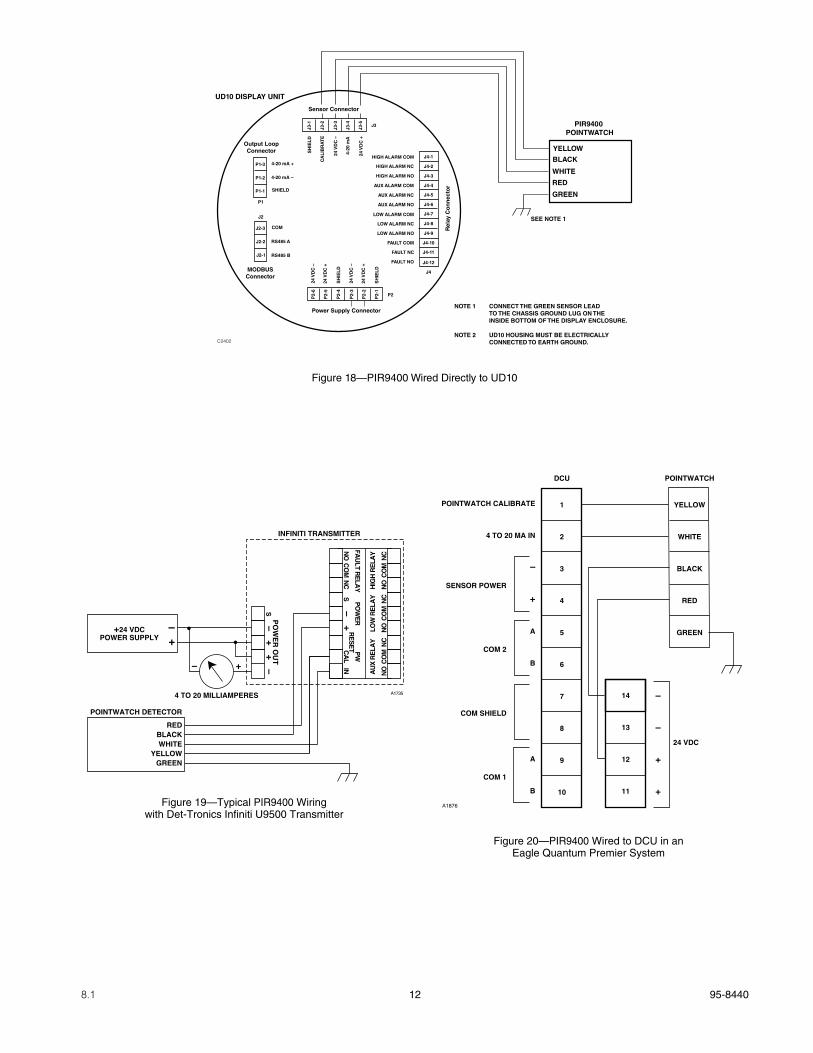
3. Figures 15 through 20 show typical wiring for various system configurations using the Model PIR9400 detector. Refer to the appropriate figure as a guide to system connection. Figure 15 shows typical wiring for stand alone operation. Figure 16 shows typical wiring for the PIR9400 with Det-Tronics supplied termination box. Figure 17 shows the termination box terminals and calibration switch. Figure 18 shows wiring for PIR9400/FlexVu UD10 operation. Figure 19 shows typical wiring for PIR9400/Infiniti U9500 transmitter operation. Figure 20 shows a PIR9400 wired to a DCU in an Eagle Quantum Premier system. The PIR9400 wiring color code is:
Red lead = +24 Vdc Black lead = – (common) White lead = 4–20 mA signal output Yellow lead* = Calibration input Green lead = Chassis ground.
* If the calibration wire (yellow lead) is not being used, do not connect this wire to ground. Trim excess length and insulate wire so no shorting can occur.
4. Check the detector wiring to ensure proper connections, then pour the conduit seals and allow them to dry (if conduit is being used).
Figure 15—Typical PIR9400 Detector Wiring, Stand Alone Configuration
–
REDBLACKWHITE
YELLOWGREEN
4 TO 20 MILLIAMPERESPOINTWATCH DETECTOR
+
A1755
NOTE: CALIBRATION PUSHBUTT0N, CURRENT METER AND POWER SUPPLY ARE NOT SUPPLIED.
+24 VDCPOWER SUPPLY–
+
CALIBRATE
Figure 16—Typical PIR9400 Wiring, PIR9400 with PIRTB
+24 VDC POWER OUT
4 TO 20 MILLIAMPERES IN
POINTWATCHDETECTOR
DET-TRONICS TERMINATION BOX
–+
A1756
GREENYELLOWWHITEBLACKRED
SPARE
CAL
4 – 20
RET
+24
CHASSIS
CAL
4 – 20
RET
+24
Figure 17—PIRTB Terminals and Calibration Switch
CALIBRATE SWITCH
B2056
HOLD CALIBRATION MAGNETAT OUTSIDE BASE OF JUNCTION BOX AT THIS LOCATIONTO ACTIVATE CALIBRATION SWITCH
REMOTE LED
12 95-84408.1
Figure 19—Typical PIR9400 Wiring with Det-Tronics Infiniti U9500 Transmitter
+24 VDCPOWER SUPPLY
4 TO 20 MILLIAMPERES
INFINITI TRANSMITTER
+
+
–
–
PO
WE
R O
UT
NO
CO
MN
CN
OC
OM
NC
NO
CO
M
AU
X R
ELA
YLO
W R
ELA
YH
IGH
RE
LAY
NC
NO
CO
MN
CS
–+
S–
–+
+
RE
SE
TCA
L
FAU
LT RE
LAY
PO
WE
RP
W
IN
A1735
REDBLACKWHITE
YELLOWGREEN
POINTWATCH DETECTOR
1
2
3
4
5
6
7
8
9
10
YELLOW
WHITE
BLACK
RED
GREEN
DCU POINTWATCH
14
13
12
11
–
–
+
+
24 VDC
POINTWATCH CALIBRATE
4 TO 20 MA IN
–
+
A
B
A
B
SENSOR POWER
COM 2
COM SHIELD
COM 1
A1876
Figure 20—PIR9400 Wired to DCU in anEagle Quantum Premier System
UD10 DISPLAY UNIT
PIR9400 POINTWATCH
BLACK
RED
YELLOW
WHITE
GREEN
SEE NOTE 1
NOTE 1 CONNECT THE GREEN SENSOR LEAD TO THE CHASSIS GROUND LUG ON THE INSIDE BOTTOM OF THE DISPLAY ENCLOSURE.
NOTE 2 UD10 HOUSING MUST BE ELECTRICALLY CONNECTED TO EARTH GROUND.C2402
Sensor Connector
Power Supply Connector
Output LoopConnector
MODBUSConnector
Rel
ay C
on
nec
tor
P1
J2
J3
J4
P2
4-20 mA +
4-20 mA –
SHIELD
COM
RS485 A
RS485 B
HIGH ALARM COM
HIGH ALARM NC
HIGH ALARM NO
AUX ALARM COM
AUX ALARM NC
AUX ALARM NO
LOW ALARM COM
LOW ALARM NC
LOW ALARM NO
FAULT COM
FAULT NC
FAULT NO
24 V
DC
–
24 V
DC
+
SH
IEL
D
24 V
DC
–
24 V
DC
+
SH
IEL
D
SH
IEL
D
CA
LIB
RA
TE
24 V
DC
–
4-20
mA
24 V
DC
+
P1-3
P1-2
P1-1
J2-3
J2-2
J2-1
J4-1
J4-2
J4-3
J4-4
J4-5
J4-6
J4-7
J4-8
J4-9
J4-10
J4-11
J4-12
J3-1
J3-2
J3-3
J3-4
J3-5
P2-
6
P2-
5
P2-
4
P2-
3
P2-
2
P2-
1Figure 18—PIR9400 Wired Directly to UD10
13 95-84408.1
DETECTOR SEpaRaTION (OpTIONaL)
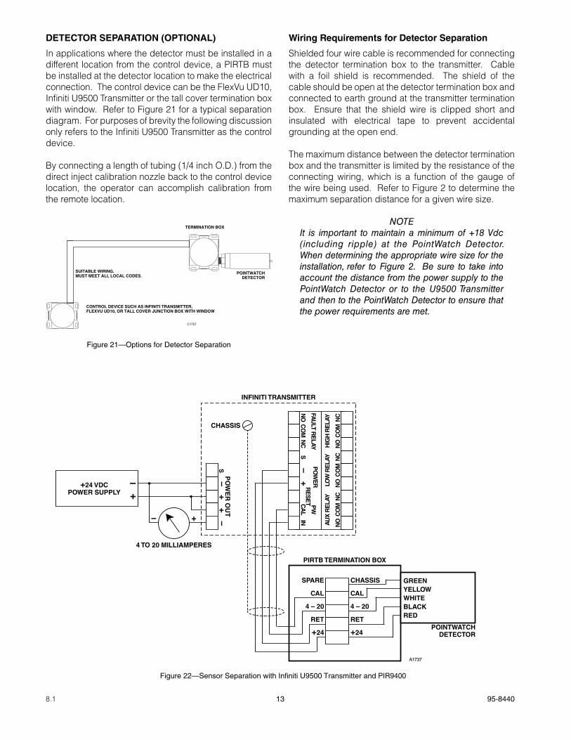
In applications where the detector must be installed in a different location from the control device, a PIRTB must be installed at the detector location to make the electrical connection. The control device can be the FlexVu UD10, Infiniti U9500 Transmitter or the tall cover termination box with window. Refer to Figure 21 for a typical separation diagram. For purposes of brevity the following discussion only refers to the Infiniti U9500 Transmitter as the control device.
By connecting a length of tubing (1/4 inch O.D.) from the direct inject calibration nozzle back to the control device location, the operator can accomplish calibration from the remote location.
Wiring Requirements for Detector Separation
Shielded four wire cable is recommended for connecting the detector termination box to the transmitter. Cable with a foil shield is recommended. The shield of the cable should be open at the detector termination box and connected to earth ground at the transmitter termination box. Ensure that the shield wire is clipped short and insulated with electrical tape to prevent accidental grounding at the open end.
The maximum distance between the detector termination box and the transmitter is limited by the resistance of the connecting wiring, which is a function of the gauge of the wire being used. Refer to Figure 2 to determine the maximum separation distance for a given wire size.
NOTE It is important to maintain a minimum of +18 Vdc (including ripple) at the PointWatch Detector. When determining the appropriate wire size for the installation, refer to Figure 2. Be sure to take into account the distance from the power supply to the PointWatch Detector or to the U9500 Transmitter and then to the PointWatch Detector to ensure that the power requirements are met.
+24 VDCPOWER SUPPLY
4 TO 20 MILLIAMPERES
INFINITI TRANSMITTER
PIRTB TERMINATION BOX
CHASSIS
+
+
–
–
PO
WE
R O
UT
NO
CO
MN
CN
OC
OM
NC
NO
CO
M
AU
X R
ELA
YLO
W R
ELA
YH
IGH
RE
LAY
NC
NO
CO
MN
CS
–+
S–
–+
+
RE
SE
TCA
L
FAU
LT RE
LAYP
OW
ER
PW
IN
A1737
SPARE
CAL
4 – 20
RET
+24
CHASSIS
CAL
4 – 20
RET
+24POINTWATCH
DETECTOR
GREENYELLOWWHITEBLACKRED
Figure 22—Sensor Separation with Infiniti U9500 Transmitter and PIR9400
TERMINATION BOX
POINTWATCHDETECTOR
SUITABLE WIRING.MUST MEET ALL LOCAL CODES.
CONTROL DEVICE SUCH AS INFINITI TRANSMITTER,FLEXVU UD10, OR TALL COVER JUNCTION BOX WITH WINDOW
C1757
Figure 21—Options for Detector Separation
14 95-84408.1
Mounting and Connecting procedure for Detector Separation
The PIRTB can be mounted to a wall or post, or it can be suspended by the conduit if this does not result in excessive vibration. A 3/8 inch spacer may be needed between the termination box and the mounting surface to allow adequate room for the sensor and calibration accessory. The termination box should be electrically connected to earth ground.
1. Lubricate the sensor threads with low vapor pressure silicone grease, then install the sensor in the conduit entry of the termination box. It should be tight to ensure an explosion-proof installation, however, do not overtighten.
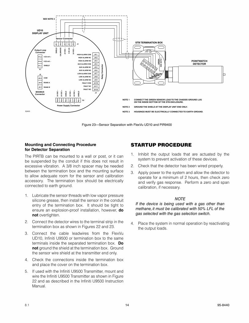
2. Connect the detector wires to the terminal strip in the termination box as shown in Figures 22 and 23.
3. Connect the cable leadwires from the FlexVu UD10, Infiniti U9500 or termination box to the same terminals inside the separated termination box. Do not ground the shield at the termination box. Ground the sensor wire shield at the transmitter end only.
4. Check the connections inside the termination box and place the cover on the termination box.
5. If used with the Infiniti U9500 Transmitter, mount and wire the Infiniti U9500 Transmitter as shown in Figure 22 and as described in the Infiniti U9500 Instruction Manual.
STARTUP PROCEDURE
1. Inhibit the output loads that are actuated by the system to prevent activation of these devices.
2. Check that the detector has been wired properly.
3. Apply power to the system and allow the detector to operate for a minimum of 2 hours, then check zero and verify gas response. Perform a zero and span calibration, if necessary.
NOTEIf the device is being used with a gas other than methane, it must be calibrated with 50% LFL of the gas selected with the gas selection switch.
4. Place the system in normal operation by reactivating the output loads.
NOTE 1 CONNECT THE GREEN SENSOR LEAD TO THE CHASSIS GROUND LUG ON THE INSIDE BOTTOM OF THE STB ENCLOSURE.
NOTE 2 GROUND THE SHIELD AT THE DISPLAY UNIT END ONLY.
NOTE 3 HOUSINGS MUST BE ELECTRICALLY CONNECTED TO EARTH GROUND.
UD10 DISPLAY UNIT
POINTWATCHDETECTOR
SEE NOTE 2
E2403
Sensor Connector
Power Supply Connector
Output LoopConnector
MODBUSConnector
Rel
ay C
on
nec
tor
P1
J2
J3
J4
P2
4-20 mA +
4-20 mA –
SHIELD
COM
RS485 A
RS485 B
HIGH ALARM COM
HIGH ALARM NC
HIGH ALARM NO
AUX ALARM COM
AUX ALARM NC
AUX ALARM NO
LOW ALARM COM
LOW ALARM NC
LOW ALARM NO
FAULT COM
FAULT NC
FAULT NO
24 V
DC
–
24 V
DC
+
SH
IEL
D
24 V
DC
–
24 V
DC
+
SH
IEL
D
SH
IEL
D
CA
LIB
RA
TE
24 V
DC
–
4-20
mA
24 V
DC
+
P1-3
P1-2
P1-1
J2-3
J2-2
J2-1
J4-1
J4-2
J4-3
J4-4
J4-5
J4-6
J4-7
J4-8
J4-9
J4-10
J4-11
J4-12
J3-1
J3-2
J3-3
J3-4
J3-5
P2-
6
P2-
5
P2-
4
P2-
3
P2-
2
P2-
1RED
YELLOW
WHITE
GR
EE
NS
EE
NO
TE
1
STB TERMINATION BOX
BLACK
Figure 23—Sensor Separation with FlexVu UD10 and PIR9400
15 95-84408.1
CALIBRATION
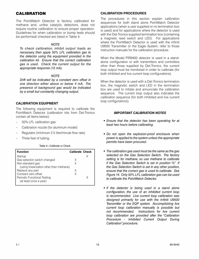
The PointWatch Detector is factory calibrated for methane and, unlike catalytic detectors, does not require routine calibration to ensure proper operation. Guidelines for when calibration or bump tests should be performed/ checked are listed in Table 4.
NOTETo check calibration, inhibit output loads as necessary, then apply 50% LFL calibration gas to the detector using the equipment provided in the calibration kit. Ensure that the correct calibration gas is used. Check the current output for the appropriate response (12 mA).
NOTEDrift will be indicated by a constant zero offset in one direction either above or below 4 mA. The presence of background gas would be indicated by a small but constantly changing output.
CaLIBRaTION EqUIpMENT
The following equipment is required to calibrate the PointWatch Detector (calibration kits from Det-Tronics contain all items below):
– 50% LFL calibration gas
– Calibration nozzle (for aluminum model)
– Regulator (minimum 2.5 liter/minute flow rate)
– Three feet of tubing.
CaLIBRaTION pROCEDURES
The procedures in this section explain calibration sequences for both stand alone PointWatch Detector applications (when a user supplied or no termination box is used) and for applications where the detector is used with the Det-Tronics supplied termination box (containing a magnetic reed switch and LED). For applications where the PointWatch Detector is used with the Infiniti U9500 Transmitter or the Eagle System, refer to those instruction manuals for the calibration procedure.
When the Model PIR9400 detector is used in a stand-alone configuration or with transmitters and controllers other than those supplied by Det-Tronics, the current loop output must be monitored in order to calibrate (for both inhibited and live current loop configurations).
When the detector is used with a Det-Tronics termination box, the magnetic switch and LED in the termination box are used to initiate and annunciate the calibration sequence. The current loop output also indicates the calibration sequence (for both inhibited and live current loop configurations).
iMPoRtant CaLiBRation notES
•Ensure that the detector has been operating for at least two hours before calibrating.
•Do not open the explosion-proof enclosure when power is applied to the system unless the appropriate permits have been procured.
•The calibration gas used must be the same as the gas selected on the Gas Selection Switch. The factory setting is for methane, so use methane to calibrate if the Gas Selection Switch is set in position “0.” If the Gas Selection Switch is set in any other position, ensure that the correct gas is used to calibrate. See Figure 14. Only 50% LFL calibration gas can be used to calibrate the PointWatch Detector.
• If the detector is being used in a stand alone configuration, the use of an inhibited current loop is recommended. Live current loop calibration was designed primarily for use with the Infiniti U9500 Transmitter or the EQP system. Accomplishing live current loop calibration manually is possible but not recommended. Instructions for live current loop calibration are provided after the “Calibration Procedure - Inhibited Current Output During Calibration” procedure.
Table 4—Calibrate or Check
Function Calibrate Check
Startup XGas selection switch changed XNon-standard gas X (using linearization other than methane)Replace any part XConstant zero offset XPeriodic Functional Testing X (at least once a year)
16 95-84408.1
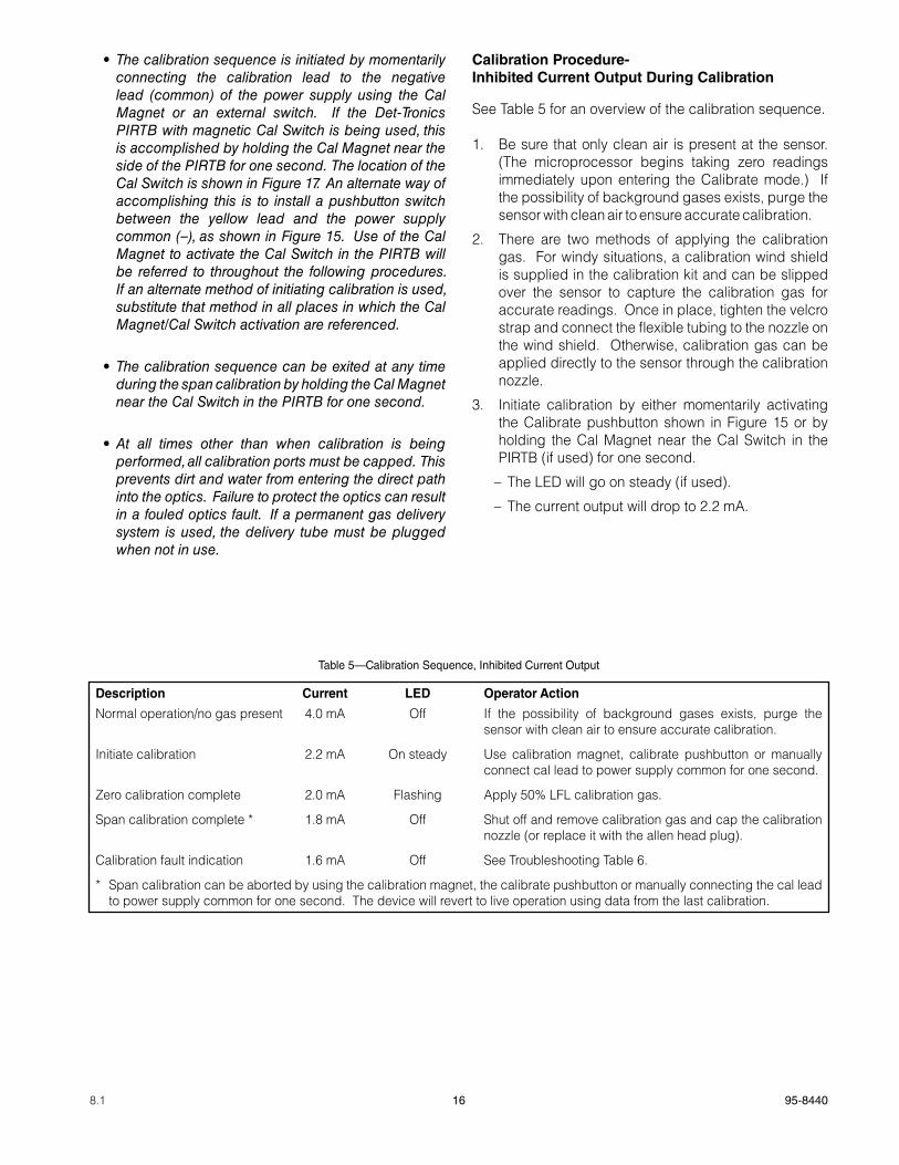
•The calibration sequence is initiated by momentarily connecting the calibration lead to the negative lead (common) of the power supply using the Cal Magnet or an external switch. If the Det-Tronics PIRTB with magnetic Cal Switch is being used, this is accomplished by holding the Cal Magnet near the side of the PIRTB for one second. The location of the Cal Switch is shown in Figure 17. An alternate way of accomplishing this is to install a pushbutton switch between the yellow lead and the power supply common (–), as shown in Figure 15. Use of the Cal Magnet to activate the Cal Switch in the PIRTB will be referred to throughout the following procedures. If an alternate method of initiating calibration is used, substitute that method in all places in which the Cal Magnet/Cal Switch activation are referenced.
•The calibration sequence can be exited at any time during the span calibration by holding the Cal Magnet near the Cal Switch in the PIRTB for one second.
•At all times other than when calibration is being performed, all calibration ports must be capped. This prevents dirt and water from entering the direct path into the optics. Failure to protect the optics can result in a fouled optics fault. If a permanent gas delivery system is used, the delivery tube must be plugged when not in use.
Calibration procedure- Inhibited Current Output During Calibration
See Table 5 for an overview of the calibration sequence.
1. Be sure that only clean air is present at the sensor. (The microprocessor begins taking zero readings immediately upon entering the Calibrate mode.) If the possibility of background gases exists, purge the sensor with clean air to ensure accurate calibration.
2. There are two methods of applying the calibration gas. For windy situations, a calibration wind shield is supplied in the calibration kit and can be slipped over the sensor to capture the calibration gas for accurate readings. Once in place, tighten the velcro strap and connect the flexible tubing to the nozzle on the wind shield. Otherwise, calibration gas can be applied directly to the sensor through the calibration nozzle.
3. Initiate calibration by either momentarily activating the Calibrate pushbutton shown in Figure 15 or by holding the Cal Magnet near the Cal Switch in the PIRTB (if used) for one second.
– The LED will go on steady (if used).
– The current output will drop to 2.2 mA.
Description Current LED Operator action
Normal operation/no gas present 4.0 mA Off If the possibility of background gases exists, purge the sensor with clean air to ensure accurate calibration.
Initiate calibration 2.2 mA On steady Use calibration magnet, calibrate pushbutton or manually connect cal lead to power supply common for one second.
Zero calibration complete 2.0 mA Flashing Apply 50% LFL calibration gas.
Span calibration complete * 1.8 mA Off Shut off and remove calibration gas and cap the calibration nozzle (or replace it with the allen head plug).
Calibration fault indication 1.6 mA Off See Troubleshooting Table 6.
* Span calibration can be aborted by using the calibration magnet, the calibrate pushbutton or manually connecting the cal lead to power supply common for one second. The device will revert to live operation using data from the last calibration.
Table 5—Calibration Sequence, Inhibited Current Output
17 95-84408.1
4. Wait for the zero calibration point to stabilize (typically 1 minute).
After successful zero calibration: – The LED will begin flashing (if used),
– The current will drop to 2.0 mA.
Proceed to step 5.
If zero calibration fails:
– The LED will turn off,
– The current output will drop to 1.6 mA.
Reset the detector by cycling power to the detector or by holding the Cal Magnet near the Cal Switch in the PIRTB (if used) for one second. Begin calibration again at step 1.
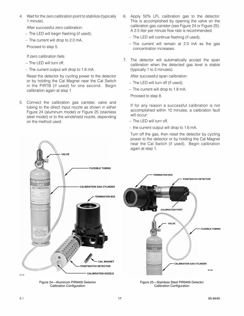
5. Connect the calibration gas canister, valve and tubing to the direct input nozzle as shown in either Figure 24 (aluminum model) or Figure 25 (stainless steel model) or to the windshield nozzle, depending on the method used.
6. Apply 50% LFL calibration gas to the detector. This is accomplished by opening the valve on the calibration gas canister (see Figure 24 or Figure 25). A 2.5 liter per minute flow rate is recommended.
– The LED will continue flashing (if used),
– The current will remain at 2.0 mA as the gas concentration increases.
7. The detector will automatically accept the span calibration when the detected gas level is stable (typically 1 to 2 minutes).
After successful span calibration:
– The LED will turn off (if used),
– The current will drop to 1.8 mA.
Proceed to step 8.
If for any reason a successful calibration is not accomplished within 10 minutes, a calibration fault will occur: – The LED will turn off,
– the current output will drop to 1.6 mA.
Turn off the gas, then reset the detector by cycling power to the detector or by holding the Cal Magnet near the Cal Switch (if used). Begin calibration again at step 1.
Figure 24—Aluminum PIR9400 Detector Calibration Configuration
TERMINATION BOX
FLEXIBLE TUBING
CAL MAGNET
POINTWATCH DETECTOR
B1745CALIBRATION NOZZLE
VALVE
CALIBRATION GAS CYLINDER
Figure 25—Stainless Steel PIR9400 Detector Calibration Configuration
TERMINATION BOX
FLEXIBLE TUBING
POINTWATCH DETECTOR
B1746
CALIBRATION PORT
VALVE
CALIBRATION GAS CYLINDER
18 95-84408.1
8. After successful calibration, close the valve on the calibration gas canister, remove the flexible tube from the calibration nozzle and replace the nozzle cap. If the calibration wind shield was used, remove it from the PointWatch Detector. The detector will return to normal operation after the gas level has returned below 5% LFL.
iMPoRtantThe calibration ports must be capped to prevent dirt and water from entering the direct path into the optics. Failure to protect the optics can result in a fouled optics fault. If a permanent gas delivery system is used, the delivery tube must be plugged when not in use.
Calibration procedure - Live Current Output During Calibration
Sequence Summary: During calibration with a live current loop output, the current output drops to 2.2 mA during the zero calibration then rises to reflect the actual gas level for the span calibration. At the end of calibration, the current level locks to indicate that the calibration is complete. These current levels and their significance are summarized as follows:
4.0 mA Zero gas level (0% LFL), initial state - normal operation, no gas present
2.2 mA Zero calibration in progress
12.0 mA Span calibration lock-in
1.6 mA Calibration fault - reset unit.
iMPoRtant LiVE CuRREnt outPut CaLiBRation notES
• If the PIR9400 is being used in a stand alone configuration, the use of an inactive current loop is recommended. Live current loop calibration was designed primarily for use with the Infiniti U9500 Transmitter or the EQP system. Accomplishing live current loop calibration manually is difficult because precision timing is required.
• Inhibit alarm outputs before performing this calibration procedure. Alarm levels will be exceeded using the live current output calibration procedure.
•All calibration notes listed at the beginning of the “Calibration Procedures” section also apply to this procedure. Review those notes prior to proceeding.
1. Be sure that only clean air is present at the sensor. (The microprocessor begins taking zero readings immediately upon entering the Calibrate mode.) If the possibility of background gases exists, purge the sensor with clean air to ensure accurate calibration.
2. There are two methods of applying the calibration gas. For windy situations, a calibration wind shield is supplied in the calibration kit and can be slipped over the sensor to capture the calibration gas for accurate readings. Once in place, tighten the velcro strap. Otherwise, calibration gas can be applied directly to the sensor through the calibration nozzle.
3. Initiate calibration by either momentarily activating the Calibrate pushbutton shown in Figure 15 or by holding the Cal Magnet near the Cal Switch in the PIRTB (if used) for one second.
– The LED will go on steady and the current output will drop to 2.2 mA. After the zero is stable (typically 1 minute), the LED will start to flash and the current level changes to 2.0 mA. When the LED goes off for the first flash, immediately reactivate the calibration switch for one second only. This places the current loop output in the live mode.
– The current level rises to 4.0 mA and the LED begins flashing.
If unsuccessful at entering live calibration mode, abort calibration by momentarily reactivating the magnetic calibration switch or pressing the calibrate pushbutton. Repeat steps 1 - 3.
Proceed to step 4.
If calibration mode was inadvertently exited: – The LED will turn off,
– the current output will remain at 4.0 mA (normal operation).
This occurs when the Cal switch is activated for too
long when the LED begins flashing. Repeat all of step 3 and proceed.
If zero calibration fails: – The LED will turn off,
– the current output will drop to 1.6 mA.
Reset the detector by cycling power to the detector or by holding the Cal Magnet near the Cal Switch in the PIRTB (if used) for one second. Begin calibration again at step 1.

19 95-84408.1
4. Connect the calibration gas canister, valve and tubing to the direct input nozzle as shown in either Figure 24 (aluminum model) or Figure 25 (stainless steel model) or to the windshield nozzle, depending on the method used.
5. Apply 50% LFL calibration gas to the detector. This is accomplished by opening the valve on the calibration gas canister (see Figure 24 or Figure 25). A 2.5 liter per minute flow rate is recommended.
– The LED will continue flashing,
– The current output will increase proportionally as the gas concentration increases.
6. The detector will automatically accept the span calibration when the detected gas level is stable (typically 1 to 2 minutes).
After successful span calibration: – The LED will turn off steady,
– the current will lock in steadily at 12.0 mA, indicating a successful span calibration.
Proceed to step 7.
If for any reason a successful calibration is not accomplished within 10 minutes, a calibration fault will occur:— The LED will turn off,— the current output will drop to 1.6 mA.
Turn off the gas, then reset the detector by cycling power to the detector or by holding the Cal Magnet near the Cal Switch. Begin the calibration sequence again at step 1.
7. After successful calibration, close the valve on the calibration gas canister, remove the flexible tube from the calibration nozzle and replace the nozzle cap. If the calibration wind shield was used, remove it from the detector. After the detector out-put falls below 45% LFL, the current loop will unlock and will track the declining gas concentration back to 4 mA.
iMPoRtantThe calibration ports must be capped to prevent dirt and water from entering the direct path into the optics. Failure to protect the optics can result in a fouled optics fault. If a permanent gas delivery system is used, the delivery tube must be plugged when not in use.
MAINTENANCE
The PointWatch Detector requires less routine maintenance than other combustible gas detectors. This is accomplished through its design that allows no undisclosed internal failures, and an optics protection system that is extremely resistant to fouling by external contamination. The most significant benefit of this design is reduced calibration requirements. When installed and used per the manufacturer’s recommendations, the Model PIR9400 detector does not require routine calibration, although an annual calibration inspection is recommended as a good practice. More frequent calibrations may be performed at the discretion of the user without adverse impact.
Other recommended maintenance practices include periodic visual inspections of the sensor and/or weather protection system. External contaminants and/or debris, if allowed to accumulate, can reduce sensitivity by physically blocking vapor access to the sensor. Common examples include plastic bags, litter, heavy oil and tar, paint, mud, and snow. This simple visual inspection of all gas sensors is a good idea, especially for outdoor installations.
In the unlikely event that the PIR9400 indicates a fouled optics condition, it is possible to disassemble and clean the optics. However, it is recommended that a spare device be kept on hand to enable complete exchange of the electronics/optics module in the field, enabling the disassembly and cleaning operation to be performed in a clean lab environment.
iMPoRtant MaintEnanCE notES
•use only low vapor pressure silicone grease when lubricating threads on the PointWatch Detector and associated termination box. Do not get this grease on the optics of the detector. A suitable grease is listed in the “Spare Parts” section at the end of this manual. Do not use Hydrocarbon-based grease. Doing so will emit hydrocarbon vapors that will be measured by the detector, resulting in inaccurate gas level readings.
• In applications where both PIR9400 and catalytic type sensors are used, ensure that the silicone grease used to lubricate the detector threads does not come into contact with the catalytic sensors or poisoning of the catalytic sensors will result. It is strongly recommended that maintenance personnel wash their hands between handling the two types of sensors.
20 95-84408.1
DISaSSEMBLy aND CLEaNINg pROCEDURE
The PointWatch Detector should be inspected periodically to ensure that its performance is not impaired by fouled optics or by clogging of the filter or hydrophobic filter. Inspection and/or periodic maintenance involves three different areas of the detector.
iMPoRtantRemove power before disconnecting and removing the detector for maintenance.
NOTEIt is not necessary to remove the electronics assembly from the detector base assembly in order to clean the detector optics.
Filter/Baffle. Perform a visual inspection of the filter/baffle, checking for a variety of environmental contaminants including nests of insects, spiders, etc. Disassemble the PIR9400 and clean as necessary.
hydrophobic Filter (used on all aluminum and select stainless steel models). While clogging of the hydrophobic filter is rare in most installations, the flow of gas through the filter can be inhibited by an accumulation of extremely fine particles of airborne contaminants. To inspect the hydrophobic filter, disassemble the PIR9400 as described in this section. If the filter appears to be fouled, replace it. As an alternate to a visual inspection of the filter, the PointWatch Detector can be tested using the PointWatch Wind Shield Calibration Bag, available from Det-Tronics. (Plug the detector calibration port, then attach the Wind Shield Calibration Bag snugly to the detector. Apply calibration gas through the tubing connected to the Wind Shield Calibration Bag).
iMPoRtantThe hydrophobic filter should be replaced whenever the mirror assembly and reflector tubes are cleaned or replaced, or when the filter appears fouled upon visual inspection.
Optics. Cleaning of the optical surfaces is required only if an optical fault is indicated (1.0 mA current output signal from the detector, or an “optics fault” message on the Infiniti U9500 or FlexVu UD10). This procedure is most easily accomplished on a bench.
iMPoRtantIf the Model PIR9400 detector optics system is disassembled, calibration is required after re-assembly.
Required materials: Clean, flat work surface, foam tipped swabs (no cotton), isopropyl alcohol, screwdriver or hex wrench.
CautionThe PointWatch Detector contains semiconductor devices that are susceptible to damage by electrostatic discharge. An electrostatic charge can build up on the skin and discharge when an object is touched. Therefore, use caution when handling the device, taking care not to touch electronic components or terminals. If the electronics assembly is removed, it should be placed in an anti-static bag or box while stored or transported. A static safeguarded work area is highly recommended (if available) for disassembly and cleaning of the detector.
1. Disassemble the detector as shown in Figure 10 (aluminum) or Figure 11 (stainless steel). For aluminum models, loosen the two captive screws on the end of the detector and remove the filter assemblies. For stainless steel models, loosen the two captive screws on the end cap, then remove the baffle and stainless steel collar.
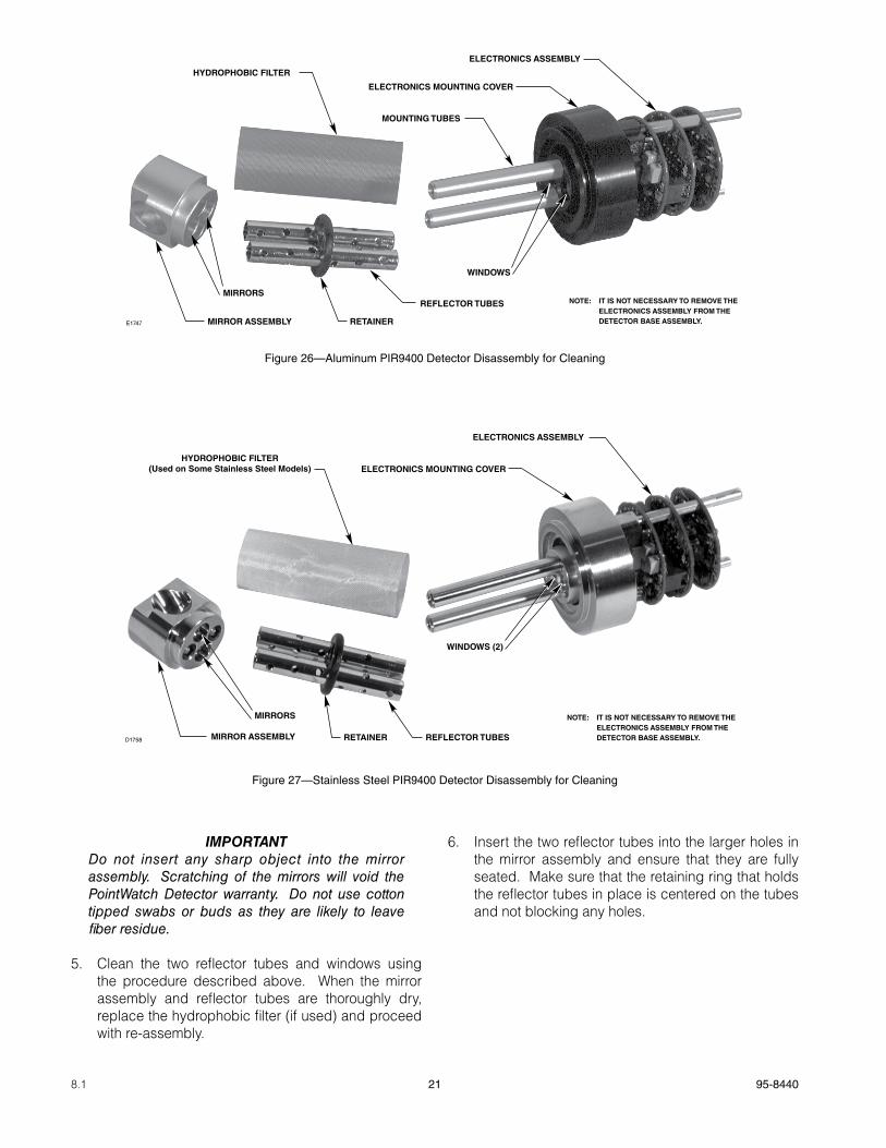
2. Loosen the two captive screws on top of the mirror assembly (Figure 12) and slide the mirror assembly, hydrophobic filter and reflector tubes away from the electronics assembly and electronics mounting cover. See Figure 26 (aluminum model) and Figure 27 (stainless steel model).
3. Disassemble the mirror assembly, reflector tubes and hydrophobic filter as shown in Figure 26 and Figure 27. Do not remove the electronics mounting cover.
4. Thoroughly douse the interior of the mirror assembly as well as the foam tipped swab with isopropyl alcohol. Use the swab to gently cleanse the surfaces of the reflecting mirrors inside the mirror assembly. After cleaning with the swab, flush out the mirror assembly using a liberal amount of isopropyl alcohol. Tip the mirror assembly with mirror openings downward to remove accumulated isopropyl alcohol and particle contaminants. Repeat the alcohol flush to remove any remaining contaminants. Allow the mirror assembly to air dry in a dust-free location.
21 95-84408.1
iMPoRtantDo not insert any sharp object into the mirror assembly. Scratching of the mirrors will void the PointWatch Detector warranty. Do not use cotton tipped swabs or buds as they are likely to leave fiber residue.
5. Clean the two reflector tubes and windows using the procedure described above. When the mirror assembly and reflector tubes are thoroughly dry, replace the hydrophobic filter (if used) and proceed with re-assembly.
6. Insert the two reflector tubes into the larger holes in the mirror assembly and ensure that they are fully seated. Make sure that the retaining ring that holds the reflector tubes in place is centered on the tubes and not blocking any holes.
Figure 26—Aluminum PIR9400 Detector Disassembly for Cleaning
ELECTRONICS MOUNTING COVER
ELECTRONICS ASSEMBLY
WINDOWS
MOUNTING TUBES
REFLECTOR TUBES
HYDROPHOBIC FILTER
MIRROR ASSEMBLY
MIRRORS
RETAINERE1747
NOTE: IT IS NOT NECESSARY TO REMOVE THE ELECTRONICS ASSEMBLY FROM THE DETECTOR BASE ASSEMBLY.
ELECTRONICS ASSEMBLY
ELECTRONICS MOUNTING COVER
WINDOWS (2)
REFLECTOR TUBESRETAINERMIRROR ASSEMBLY
MIRRORS
HYDROPHOBIC FILTER(Used on Some Stainless Steel Models)
D1758
NOTE: IT IS NOT NECESSARY TO REMOVE THE ELECTRONICS ASSEMBLY FROM THE DETECTOR BASE ASSEMBLY.
Figure 27—Stainless Steel PIR9400 Detector Disassembly for Cleaning
22 95-84408.1
NOTECheck the new hydrophobic filter to ensure that the overall length matches the length of the existing filter, or the reflector tubes if no filter was present. If the new filter appears longer than the existing filter, trim off 0.23 inch (slightly less than 1/4 inch) of material from the new filter using a scissors. Take care to not trim the filter too short, as this will allow contaminants direct access to the detector optics and cause nuisance optics faults.
7. If a hydrophobic filter is used, slide a new filter over the two mounting tubes, being careful not to fold or crumple it. The filter should be centered loosely around the two mounting tubes.
8. Carefully slide the mirror/reflector tube assembly into the hydrophobic filter and seat the reflector tubes securely into the windows in the base. Again, be careful not to crumple or fold the hydrophobic filter.
9. Tighten the two captive screws on the top of the mirror assembly. See Figure 10 (aluminum) or Figure 11 (stainless steel). Tighten the screws evenly. Do not over-tighten (apply 1 N-m minimum torque).
10. For aluminum models, slide the outer filter assembly over the mirror assembly. The outer filter should be oriented with the solid portion toward the base of the unit. If it is not oriented correctly, the filter assembly will not slide onto the unit. Slide the inner filter assembly into the outer filter assembly and rotate until it is seated securely, then fasten the two captive screws. See Figure 10.
11. For the stainless steel model, slide the stainless steel collar onto the base assembly, then slide the baffle onto the unit. Place the end cap on the baffle and rotate it until it is seated securely, then fasten the two captive screws (apply 1 N-m minimum torque). See Figure 11.
12. Calibrate the detector with 50% LFL of the gas that matches the calibration gas switch position following the instructions in the “Calibration” section of this manual.
TROUBLESHOOTING
Use Table 6 to isolate and correct malfunctions with the PointWatch Detector.
REPLACEMENT PARTS
The detector is not designed to be repaired in the field. If a problem should develop, refer to the Troubleshooting section. If it is determined that the problem is caused by an electronic defect, the device must be returned to the factory for repair.
DEVICE REPAIR AND RETURN
Prior to returning devices, contact the nearest local Detector Electronics office so that the Return Material Identification (RMI) number can be assigned. a written statement describing the malfunction must accompany the returned device or component to assist and expedite finding the root cause of the failure.
Pack the unit properly. Always use sufficient packaging material. Where applicable, use an antistatic bag as protection from electrostatic discharge.
NOTEDet-Tronics reserves the right to apply a service charge for repairing returned product damaged as a result of improper packaging.
Return all equipment transportation prepaid to the factory in Minneapolis.
NOTEIt is highly recommended that a complete spare be kept on hand for field replacement to ensure continuous protection.

23 95-84408.1
Current Level Status Corrective action
2.4 to 3.9 mA Negative Zero Indication NOTE: This phenomenon is typically caused either by the presence of background gas during zero calibration, or by condensation on the device optics. If low level background hydrocarbon gas was present during calibration, the result will be a signal output level below 4 mA when the background gas clears. To correct this, the device must be re-calibrated with all background gas removed. Purge the detector optics with Det-Tronics “zero air” calibration gas for about 30 seconds prior to initiating calibration.
In outdoor environments having high humidity coupled with rapid temperature swings, very small amounts of condensation may form on the optics, causing a temporary (up to a few hours) negative excursion below 4 mA. This phenomenon typically does not cause a loss of detection capability, and will self-correct as the heated optics dry out the residual condensation. Excursions down to the 3.0 mA level may occur without significant loss of detection capability; therefore, it is recommended that “zero drift” alert messages should be set no higher than 3.0 mA, with typical threshold settings between 2.4 and 3.0 mA.
The PIR9400 hydrophobic filter offers significant protection against condensation. Verify that the hydrophobic filter is properly installed and not crumpled or distorted to prevent a direct humidity path into the device optics.
1.6 mA Calibration fault Make sure that the calibration gas being used matches the Gas Selection Switch setting. If these match and the fault is still present, perform disassembly and cleaning procedure, then recalibrate.
1.0 mA Fouled optics Perform disassembly and cleaning procedure, then recalibrate.
0.8 mA +24 Vdc line low (less than +17.5 Vdc) Ensure that input voltage is correct and that power connections are good. If fault does not clear, replace the electronics assembly.
0.6 mA Calibrate input active at power-up Ensure that calibration line is not shorted and that the calibration switch is open. If fault does not clear, replace the unit.
0.4 mA Active channel fault Replace electronics assembly.
0.2 mA Reference channel fault Replace electronics assembly.
0.0 mA CPU system fault, warmup Ensure that power is applied and that the warmup period is complete (1 minute). If fault does not clear, replace the unit.
Table 6—Troubleshooting Table
24 95-84408.1
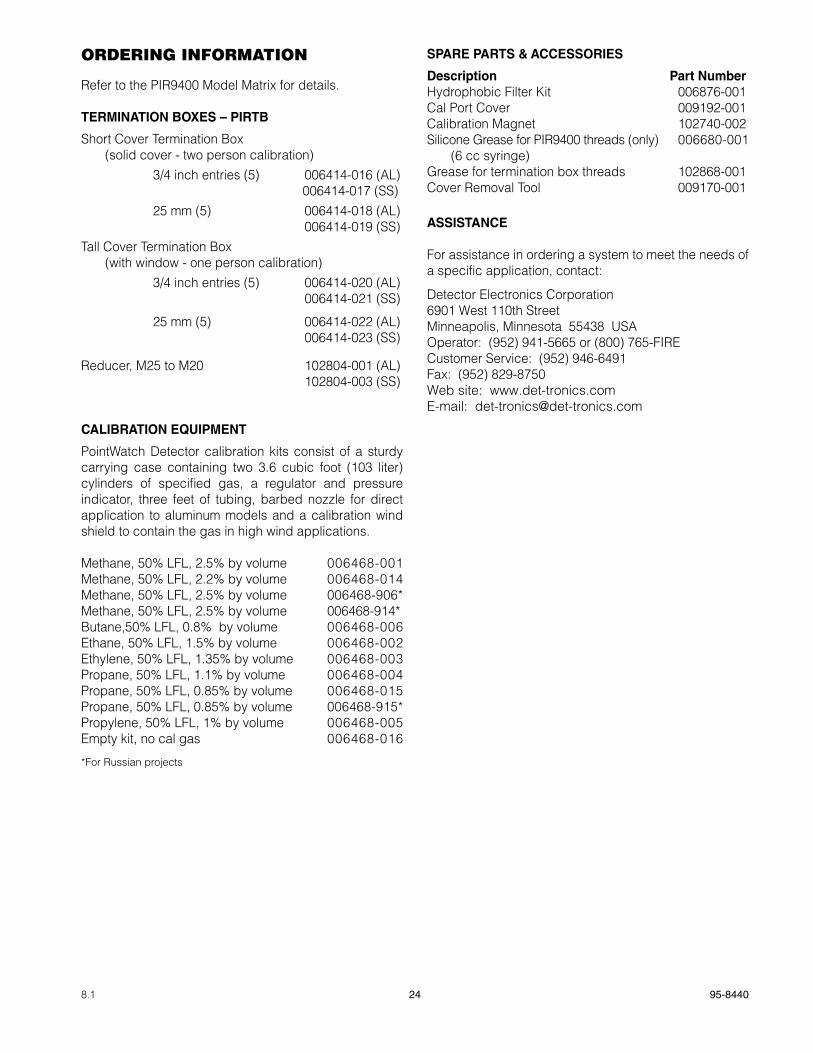
ORDERING INFORMATION
Refer to the PIR9400 Model Matrix for details.
TERMINaTION BOxES – pIRTB
Short Cover Termination Box (solid cover - two person calibration)
3/4 inch entries (5) 006414-016 (AL) 006414-017 (SS)
25 mm (5) 006414-018 (AL) 006414-019 (SS)
Tall Cover Termination Box (with window - one person calibration)
3/4 inch entries (5) 006414-020 (AL) 006414-021 (SS)
25 mm (5) 006414-022 (AL) 006414-023 (SS)
Reducer, M25 to M20 102804-001 (AL) 102804-003 (SS)
CaLIBRaTION EqUIpMENT
PointWatch Detector calibration kits consist of a sturdy carrying case containing two 3.6 cubic foot (103 liter) cylinders of specified gas, a regulator and pressure indicator, three feet of tubing, barbed nozzle for direct application to aluminum models and a calibration wind shield to contain the gas in high wind applications.
Methane, 50% LFL, 2.5% by volume 006468-001 Methane, 50% LFL, 2.2% by volume 006468-014 Methane, 50% LFL, 2.5% by volume 006468-906* Methane, 50% LFL, 2.5% by volume 006468-914*Butane,50% LFL, 0.8% by volume 006468-006 Ethane, 50% LFL, 1.5% by volume 006468-002 Ethylene, 50% LFL, 1.35% by volume 006468-003 Propane, 50% LFL, 1.1% by volume 006468-004 Propane, 50% LFL, 0.85% by volume 006468-015 Propane, 50% LFL, 0.85% by volume 006468-915* Propylene, 50% LFL, 1% by volume 006468-005 Empty kit, no cal gas 006468-016
*For Russian projects
SpaRE paRTS & aCCESSORIES
Description part NumberHydrophobic Filter Kit 006876-001Cal Port Cover 009192-001Calibration Magnet 102740-002Silicone Grease for PIR9400 threads (only) 006680-001 (6 cc syringe) Grease for termination box threads 102868-001Cover Removal Tool 009170-001
aSSISTaNCE
For assistance in ordering a system to meet the needs of a specific application, contact:
Detector Electronics Corporation6901 West 110th StreetMinneapolis, Minnesota 55438 USAOperator: (952) 941-5665 or (800) 765-FIRECustomer Service: (952) 946-6491Fax: (952) 829-8750Web site: www.det-tronics.comE-mail: [email protected]
25 95-84408.1
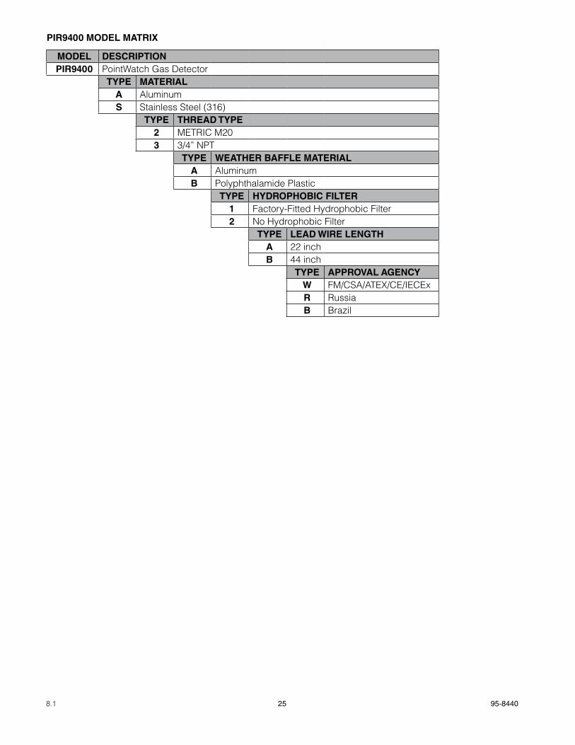
pIR9400 MODEL MaTRIx
MODEL DESCRIpTIONpIR9400 PointWatch Gas Detector
TypE MaTERIaLa AluminumS Stainless Steel (316)
TypE ThREaD TypE2 METRIC M203 3/4” NPT
TypE WEaThER BaFFLE MaTERIaLa AluminumB Polyphthalamide Plastic
TypE hyDROphOBIC FILTER1 Factory-Fitted Hydrophobic Filter2 No Hydrophobic Filter
TypE LEaD WIRE LENgTha 22 inchB 44 inch
TypE appROVaL agENCyW FM/CSA/ATEX/CE/IECExR RussiaB Brazil

26 95-84408.1
APPENDIX A
FM appROVaL
The following items, functions and options describe the FM approval.
appROVaL
PointWatch Infrared Hydrocarbon Gas Detector Model PIR9400 Series .
Explosion-proof for Class I, Division 1, Groups B, C, & D (T5) Hazardous (Classified) Locations per FM 3615. Nonincendive for Class I, Division 2, Groups A, B, C & D (T3C) Hazardous (Classified) Locations per FM 3611. Performance verified for 0 to 100% LFL Methane-in-air atmospheres per FM 6320, ANSI/ISA 12.13.01-2000.
NOTEModel PIR9400 must be used in conjunction with an FM Approved control device.
PointWatch Termination Box Model PIRTB Part Number 006414-XXX .
Explosion-proof for Class I, Division 1, Groups B, C, & D (T6) Hazardous (Classified) Locations per FM 3615. Non-incendive for Class I, Division 2, Groups A, B, C & D (T6) Hazardous (Classified) Locations per FM 3611.
NOTEApproval of the PointWatch Detector and termination box does not include or imply approval of the apparatus to which the PointWatch Detector may be connected and which processes the electronic signal for eventual end use.
Special Conditions of Use:1. Approval covers us of the instruments when calibration is performed using the gas to be monitored and the highest
alarm set points are preset within 10% of the calibration gas concentration.
2. The apparatus may be used with FM Approved PointWatch Termination Box Model PIRTB Series.
aTTaChMENTS/OpTIONS
Aluminum or Stainless Steel Explosion-proof Enclosure, with Aluminum or Plastic Baffle.3/4 inch NPT and M20 Conduit Entry Thread Types. (Metric straight thread is for use in non-North American applications.)Calibration Kit (006468-xxx) 50% LFL Calibration Gas (226166-xxx) Calibration Nozzle (102821-001) Regulator (162552-xxx) Tubing (101678-007).
CaLIBRaTION
The PointWatch Model PIR9400 can be calibrated as a stand-alone point gas detector.PointWatch Termination Box Model PIRTB (006414-xxx) can be used to calibrate the PointWatch Detector.
NOTEIt is required that calibration of the PointWatch Detector be conducted as well as calibration of the system in which it is installed.

27 95-84408.1
APPENDIX B
CSa appROVaL
The following items, functions and options describe the CSA approval.
appROVaL
PointWatch Infrared Hydrocarbon Gas Detector Model PIR9400 Series .
Explosion-proof for Class I, Division 1, Groups B, C, & D (T5) Hazardous (Classified) Locations per C22.2 #30. Nonincendive for Class I, Division 2, Groups A, B, C & D (T3C) Hazardous (Classified) Locations per C22.2 #213. Performance verified for 0 to 100% LFL Methane-in-air atmospheres per C22.2 #152.
NOTEModel PIR9400 must be used in conjunction with an CSA Approved control device.
PointWatch Termination Box Model PIRTB Part Number 006414-XXX .
Explosion-proof for Class I, Division 1, Groups B, C, & D (T6) Hazardous (Classified) Locations per C22.2 #30. Nonincendive for Class I, Division 2, Groups A, B, C & D (T6) Hazardous (Classified) Locations per C22.2 #213.
NOTEApproval of the PointWatch Detector and termination box does not include or imply approval of the apparatus to which the PointWatch Detector may be connected and which processes the electronic signal for eventual end use.
Special Conditions of Use:1. Approval covers us of the instruments when calibration is performed using the gas to be monitored and the highest
alarm set points are preset within 10% of the calibration gas concentration.
2. The apparatus may be used with CSA Approved PointWatch Termination Box Model PIRTB Series.
aTTaChMENTS/OpTIONS
Aluminum or Stainless Steel Explosion-proof Enclosure, with Aluminum or Plastic Baffle.3/4 inch NPT and M20 Conduit Entry Thread Types. (Metric straight thread is for use in non-North American applications.)Calibration Kit (006468-xxx) 50% LFL Calibration Gas (226166-xxx) Calibration Nozzle (102821-001) Regulator (162552-xxx) Tubing (101678-007).
CaLIBRaTION
The PointWatch Model PIR9400 can be calibrated as a stand-alone point gas detector.PointWatch Termination Box Model PIRTB (006414-xxx) can be used to calibrate the PointWatch Detector.
NOTEIt is required that calibration of PointWatch Detector be conducted as well as calibration of the system in which it is installed.
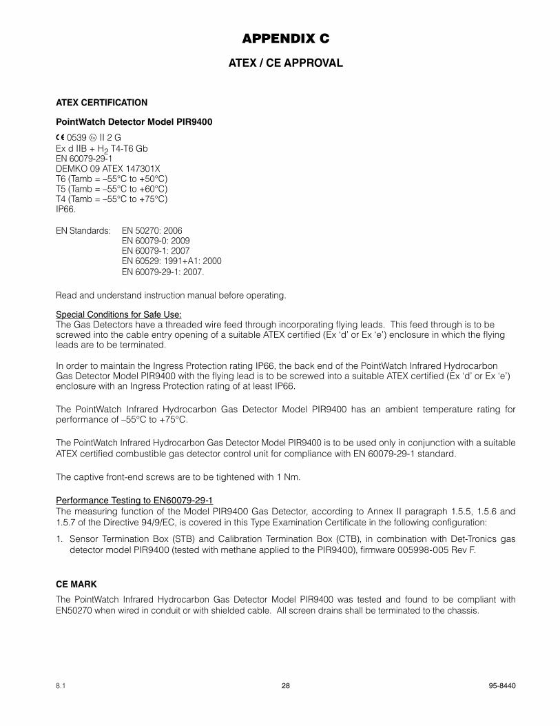
28 95-84408.1
APPENDIX C
aTEx / CE appROVaL
aTEx CERTIFICaTION
pointWatch Detector Model pIR9400
0539 FMAPPROVED
® II 2 GEx d IIB + H2 T4-T6 GbEN 60079-29-1DEMKO 09 ATEX 147301XT6 (Tamb = –55°C to +50°C)T5 (Tamb = –55°C to +60°C)T4 (Tamb = –55°C to +75°C)IP66.
EN Standards: EN 50270: 2006 EN 60079-0: 2009 EN 60079-1: 2007
EN 60529: 1991+A1: 2000 EN 60079-29-1: 2007.
Read and understand instruction manual before operating.
Special Conditions for Safe Use:The Gas Detectors have a threaded wire feed through incorporating flying leads. This feed through is to be screwed into the cable entry opening of a suitable ATEX certified (Ex ‘d’ or Ex ‘e’) enclosure in which the flying leads are to be terminated.
In order to maintain the Ingress Protection rating IP66, the back end of the PointWatch Infrared Hydrocarbon Gas Detector Model PIR9400 with the flying lead is to be screwed into a suitable ATEX certified (Ex ‘d’ or Ex ‘e’) enclosure with an Ingress Protection rating of at least IP66.
The PointWatch Infrared Hydrocarbon Gas Detector Model PIR9400 has an ambient temperature rating for performance of –55°C to +75°C.
The PointWatch Infrared Hydrocarbon Gas Detector Model PIR9400 is to be used only in conjunction with a suitable ATEX certified combustible gas detector control unit for compliance with EN 60079-29-1 standard.
The captive front-end screws are to be tightened with 1 Nm.
Performance Testing to EN60079-29-1The measuring function of the Model PIR9400 Gas Detector, according to Annex II paragraph 1.5.5, 1.5.6 and 1.5.7 of the Directive 94/9/EC, is covered in this Type Examination Certificate in the following configuration:
1. Sensor Termination Box (STB) and Calibration Termination Box (CTB), in combination with Det-Tronics gas detector model PIR9400 (tested with methane applied to the PIR9400), firmware 005998-005 Rev F.
CE MaRk
The PointWatch Infrared Hydrocarbon Gas Detector Model PIR9400 was tested and found to be compliant with EN50270 when wired in conduit or with shielded cable. All screen drains shall be terminated to the chassis.

29 95-84408.1
pointWatch Termination Box Model pIRTB
0539 FMAPPROVED
® II 2 GEx d IIC T5-T6 GbEN 60079-29-1DEMKO 02 ATEX 131326T6 (Tamb = –55°C to +60°C)T5 (Tamb = –55°C to +75°C)IP66.
EN Standards: EN 60079-0: 2009 EN 60079-1: 2007 EN 60529: 1991+A1: 2000
EN 60079-29-1: 2007.
All cable entry devices and blanking elements shall be certified in type of explosion protection flameproof enclosure ‘d’, suitable for the conditions of use and correctly installed. Unused apertures shall be closed with suitable certified blanking elements.
For ambient temperatures below –10°C and above +60°C, use field wiring suitable for both minimum and maximum ambient temperatures.
Performance testing to EN 60079-29-1The measuring function of the PointWatch Termination Box, model PIRTB, according to Annex II paragraph 1.5.5, 1.5.6 and 1.5.7 of the Directive 94/9/EC, is (for methane) covered in this EC-type Examination Certificate in the following configuration:
PointWatch Termination Box, model PIRTB, in combination with Det-Tronics gas detector models PIR9400, PIRDUCT or PIRECL (with methane applied to the gas detectors).

30 95-84408.1
APPENDIX D
IECEx appROVaL
pointWatch Detector Model pIR9400
IECEx ULD 10.0017XEx d IIB+H2 T4-T6 GbT6 (Tamb = –55°C to +50°C)T5 (Tamb = –55°C to +60°C)T4 (Tamb = –55°C to +75°C)IP66.
IEC Standards: IEC 60079-0: 2007 IEC 60079-1: 2007 IEC 60529, 2.1.ed.+Corr. 1:2003+2:2007.
CONDITIONS OF CERTIFICATION:
The PointWatch, Model PIR9400 Infrared Hydrocarbon Gas Detector has a threaded wire feed through incorporating flying leads. This feed through is to be screwed into the cable entry opening of a suitable certified (Ex ‘d’ or Ex ‘e’) enclosure in which the flying leads are to be terminated.
In order to maintain the Ingress Protection rating IP66, the back end of the PointWatch, Model PIR9400 Infrared Hydrocarbon Gas Detector with the flying lead is to be screwed into a suitable IECEx certified (Ex ‘d’ or Ex ‘e’) enclosure with an Ingress Protection rating of at least IP66.
The captive front end screws are to be tightened with 1 Nm.
pointWatch Termination Box Model pIRTB
IECEx ULD 10.0002Ex d IIC T5-T6 GbT6 (Tamb = –55°C to +60°C)T5 (Tamb = –55°C to +75°C)IP66.
IEC Standards: IEC 60079-0: 2007 IEC 60079-1: 2007 IEC 60529, 2.1.ed.+Corr. 1:2003+2:2007.
All cable entry devices and blanking elements shall be certified in type of explosion protection flameproof enclosure ‘d’, suitable for the conditions of use and correctly installed. Unused apertures shall be closed with suitable certified blanking elements.
For ambient temperatures below –10°C and above +60°C, use field wiring suitable for both minimum and maximum ambient temperatures.
31 95-84408.1
APPENDIX E
aDDITIONaL appROVaLS
gOST-R
pointWatch Detector Model pIR9400
GOST R Certificate of Compliance
Pattern Approval Certificate of Measuring Instruments.
pointWatch Termination Box Model pIRTB
GOST R Certificate of Compliance.
BRazIL
pointWatch Detector Model pIR9400
CEPEL-EX-059/97XBR-Ex d IIB+H2 T6T6 (Tamb = –55°C to +50°C).
IEC Standards: IEC 60079-0: 2007 IEC 60079-1: 2007.
pointWatch Termination Box Model pIRTB
CEPEL-EX-027/98BR-Ex d II T6T6 (Tamb = –55°C to +60°C)IP66.
IEC Standards: IEC 60079-0: 2007 IEC 60079-1: 2007 IEC 60529: 01.

95-8440
Det-Tronics, the DET-TRONICS logo, Infiniti, PointWatch Eclipse, FlexVu, and Eagle Quantum Premier are registered trademarks or trademarks of Detector Electronics Corporation in the United States, other countries, or both.
Other company, product, or service names may betrademarks or service marks of others.
© Copyright Detector Electronics Corporation 2011. All rights reserved.
Detector Electronics Corporation6901 West 110th Street
Minneapolis, MN 55438 USA
T: 952.941.5665 or 800.765.3473F: 952.829.8750
W: http://www.det-tronics.comE: [email protected]
X3301 Multispectrum IR Flame Detector
PointWatch Eclipse® IR Combustible Gas Detector
Eagle Quantum Premier® Safety System
FlexVu® Universal Displayw/ GT3000 Toxic Gas Detector