Embed Size (px)
Citation preview
US-GNRACK-IM
Section US-GNRACK-IM-001 www.enersys.com Rev. – 4/04 Page 1 of 26
INSTRUCTIONS for ASSEMBLING CLASS 1E RACKS Read all instructions carefully and observe all warnings before installation.
See Safety, Storage, Installation, Operation and Maintenance Manual for battery information.
1. GENERAL INFORMATION • EnerSys Inc. Reserve Power Class 1E
racks are available in 2 Tier and 2 Step configurations.
• Racks are supplied unassembled. The components consist of: frames, cross braces, support rails, side rails, end rails, plastic channels, corner brackets, cell clamp assemblies, foam spacers, side rail shims and assembly hardware.
2. SAFETY PRECAUTIONS • Assemble racks in accordance with the
instructions contained in this document WITHOUT DEVIATIONS.
• Refer to UBC, OSHA, and EPA regulations and local ordinances that pertain to battery installation and storage.
• Refer to additional SAFETY PRECAUTIONS contained in the EnerSys Safety, Storage, Installation, Operation and Maintenance Manual.
• Racks have multiple sets of cross braces. One set of cross braces must be removed to install cells. Do not remove more than one set of cross braces to install cells. Failure to follow these instructions may result in cells falling off the rack and causing personal injury.
• On installations where grounding is required for NEC and/or local codes, refer to the section on INSTALLATION CONSIDERATIONS in this manual.
3. SERVICE INFORMATION • Should you require installation
supervision, service, parts, accessories or maintenance, EnerSys Inc. has a service organization to assist with your new rack purchase. Contact your nearest EnerSys representative or call the corporate number listed on the back of this manual and ask for EnerSys Integrated Systems and Service.
4. INSPECTION OF BATTERY RACK COMPONENTS • Upon receipt, check each package
against the packing list to ensure all components and quantities are correct.
• Inspect for visual damage while the carrier representative is still on-site. Make note of any damage.
• If any part has not been received or has been damaged, DO NOT proceed with installation until all parts are available.
US-GNRACK-IM
Section US-GNRACK-IM-001 www.enersys.com Rev. – 4/04 Page 2 of 26
INSTRUCTIONS for ASSEMBLING CLASS 1E RACKS
5. INSTALLATION CONSIDERATIONS If you have any questions concerning the following installation considerations, contact your EnerSys sales representative. • Consider available floor space, including
aisles for cell installation, maintenance, and possible cell replacement.
• Aisle spacing should be in accordance with the NEC Article 110-16. ALL OTHER APPLICABLE CODE REQUIREMENTS SHOULD ALSO BE CONSIDERED.
• Minimum clearance between seismic racks and any objects (including walls, equipment and other racks) is to be 4 in. (100 mm). NO SEISMIC RACKS ARE TO BE BUTTED TOGETHER, END-TO-END OR BACK-TO-BACK.
• Inter-rack cable connectors provided by EnerSys are based on a rack spacing of 4 in. (100 mm); any length over this is the responsibility of the installer.
• The floor/mounting platform must be reasonably level. Shimming up to 0.25 in. (6 mm) maximum may be used to have cell support rails level both front-to-back and side-to-side. Shims and shimming hardware is user supplied.
• The floor/mounting platform must be capable of supporting the weight of the battery and rack system, as well as any auxiliary equipment. ALL APPLICABLE CODE REQUIREMENTS SHOULD BE CONSIDERED.
• Floor Anchoring and its design are the responsibility of the installer. Anchoring should meet all local, state and federal codes and industry standards.
• For rack grounding, scratch paint as necessary keeping the exposed metal to a minimum. Grounding lug and cable is user supplied. Ohmmeter readings between each component and a common point on the frame must indicate continuity to ensure proper grounding.
6. INSTALLATION EQUIPMENT and SUPPLIES Before working with the battery system, ensure that you have the tools and equipment listed below.
• Chalk line • Concrete drill (for floor anchors) • Floor shims (user-supplied) • Level • Ohmmeter (for ground testing) • Open end/box wrenches
(SAE dimensions) • Ratchet set w/ sockets
(SAE dimensions) • Square • Tape measure • Torque wrench (10-100 ft-lb.)
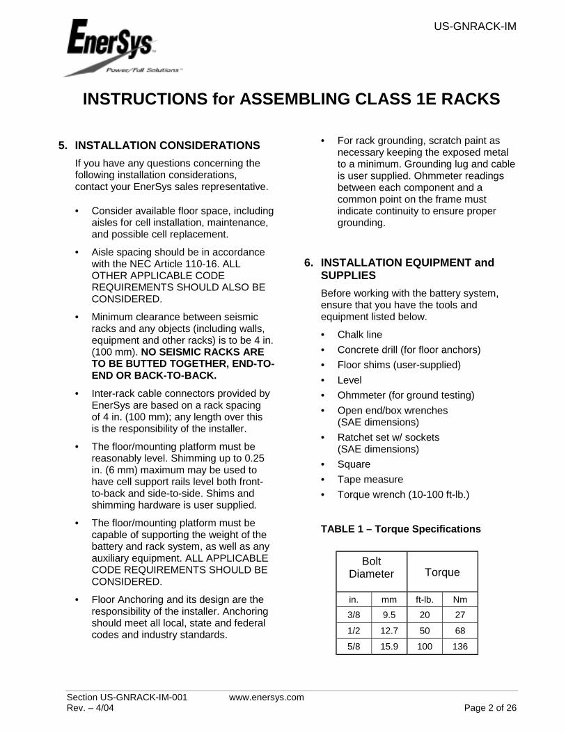
TABLE 1 – Torque Specifications
Bolt Diameter Torque
in. mm ft-lb. Nm 3/8 9.5 20 27
1/2 12.7 50 68
5/8 15.9 100 136
US-GNRACK-IM
Section US-GNRACK-IM-001 www.enersys.com Rev. – 4/04 Page 3 of 26
INSTRUCTIONS for ASSEMBLING CLASS 1E RACKS
7. RACK ASSEMBLY
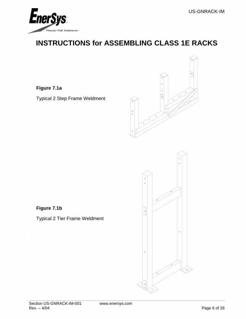
7.1 FLOOR ANCHORING Floor anchoring and its design are the responsibility of the installer. Contact your EnerSys sales representative if you have any questions. • Refer to the rack assembly drawing for
frame and anchor bolt layout. See Figures 7.1a and 7.1b.
• Mark locations for anchor bolts using the holes in the frame as a template.
• If necessary, move frame to drill and install anchor bolts.
• Drill holes and install anchor bolts as indicated in the manufacturer’s instructions.
7.2 CROSS BRACE TO FRAME
ASSEMBLY Bolt cross braces to respective frames. Refer to assembly drawing for bolt size and lengths.
• For 2 Step racks, install rear and
middle cross braces before installing cells on rack. See Figure 7.2a.
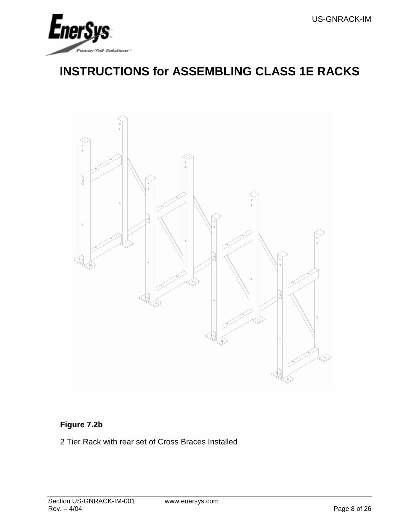
• For 2 Tier racks, install rear set of
cross braces before installing cells on rack. See Figure 7.2b
NOTE: DO NOT REMOVE multiple sets of cross braces at the same time with cells installed on the rack for safety concerns.
• Torque bolts per Table 1.
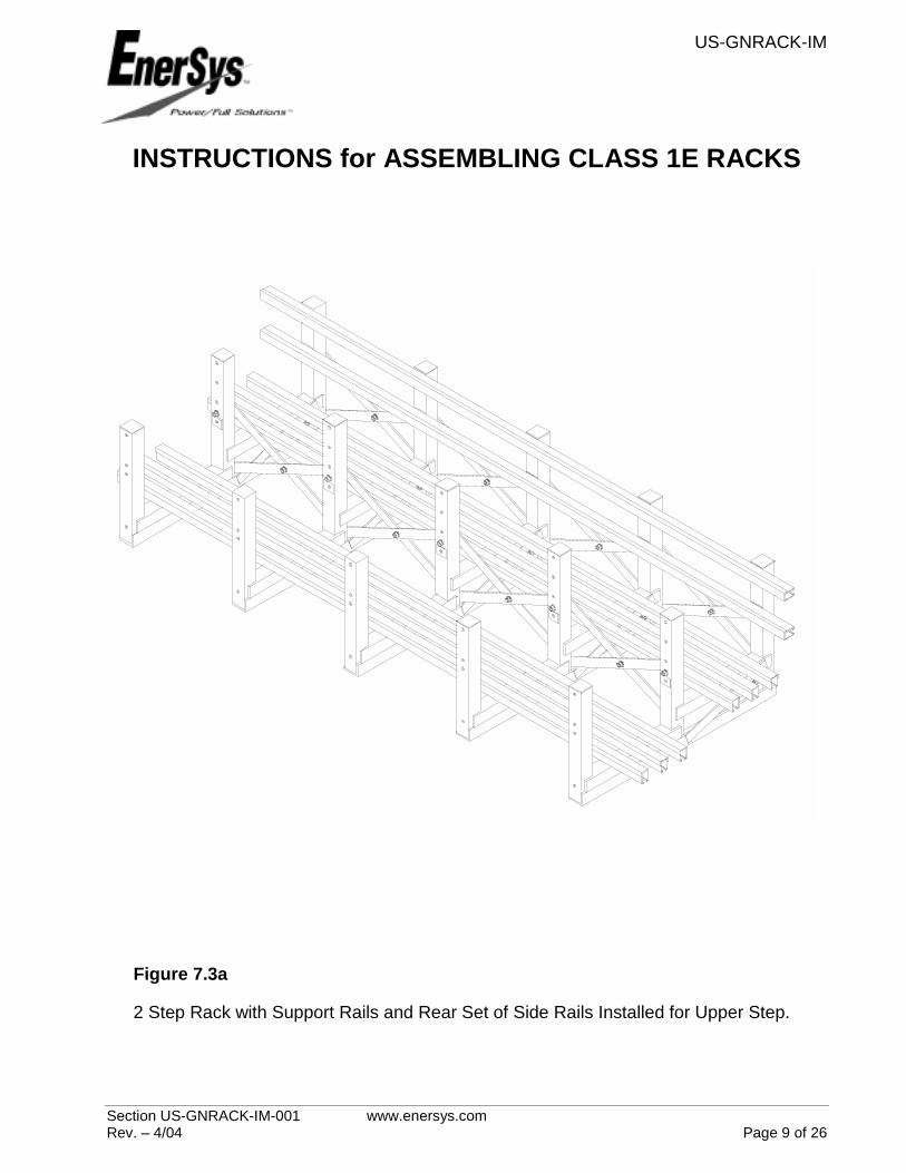
7.3 INSTALL SUPPORT RAILS & SIDE RAILS TO FRAME The rear side rail(s) will be installed before the cells and the front side(s) rail will be installed after the cells for optimum seismic protection. Refer to assembly drawing for hardware size and length. NOTE: It is recommended that the rails of the upper tiers on multi-tier racks not be installed until cells are placed on the rails of the lower tiers for safety concerns. • Locate support rails and side rail(s) so
overhang is equal on both ends. DO NOT place cells on the rack at this time. (Side rail is to be located in the upper hole of the two mounting holes if provided on the frame.) See Figures 7.3a and 7.3b.
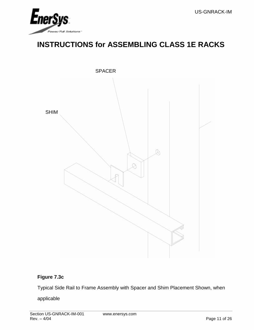
• Side rail spacer(s) may need to be
installed with side support rail. Refer to assembly drawing for spacer application and Figure 7.3c.
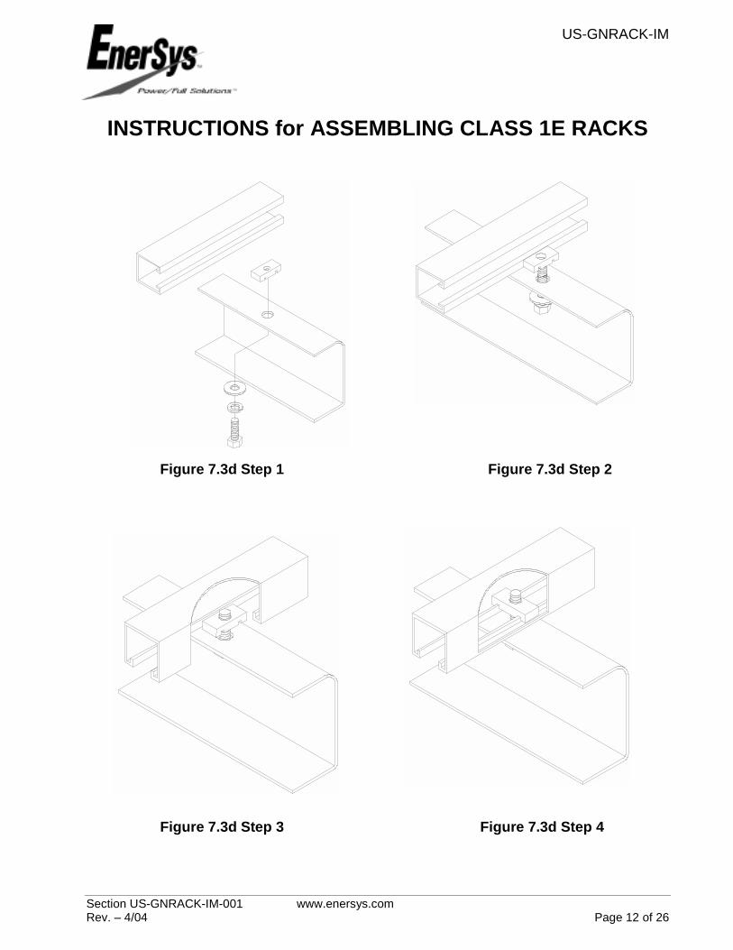
• Fasten rails to frame as shown in
Figure 7.3d, Steps 1-4. • Torque bolts per Table 1.
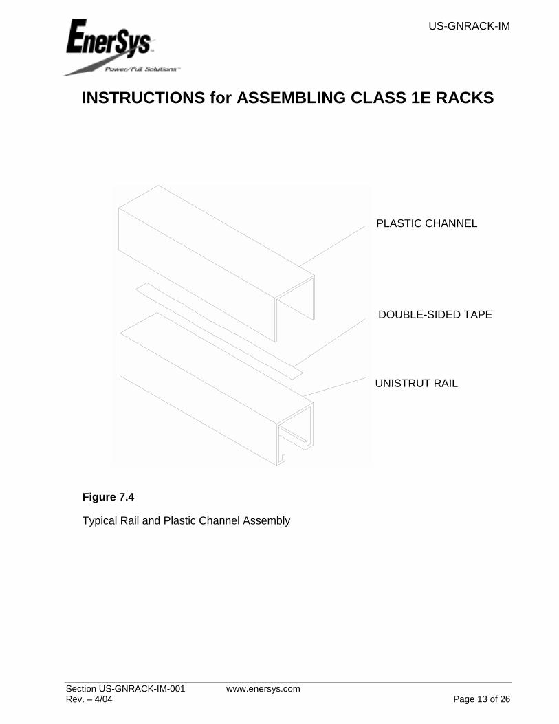
7.4 ATTACH PLASTIC CHANNEL TO
RAILS Plastic rails are supplied in 3 ft. & 4 ft. lengths. The rack shipment contains enough plastic channel to cover the support, side and end rails. • Cut plastic channels as necessary to
cover all rails. • Apply double-sided tape to the
surface of each rail, refer to Figure 7.4.

US-GNRACK-IM
Section US-GNRACK-IM-001 www.enersys.com Rev. – 4/04 Page 4 of 26
INSTRUCTIONS for ASSEMBLING CLASS 1E RACKS
7.5 CELL INSTALLATION It is important to know the location and polarity orientation of each cell prior to installation. Refer to EnerSys Safety, Storage, Installation, Operation and Maintenance Manual, provided with batteries, for installation and safety precautions. NOTE: The bottom tier should contain the largest number of cells when applicable.
• Make sure all bolts are torqued per Table 1 before installing cells.
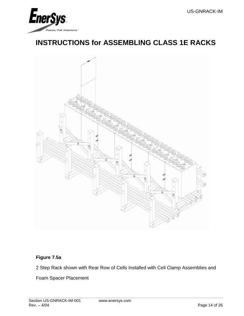
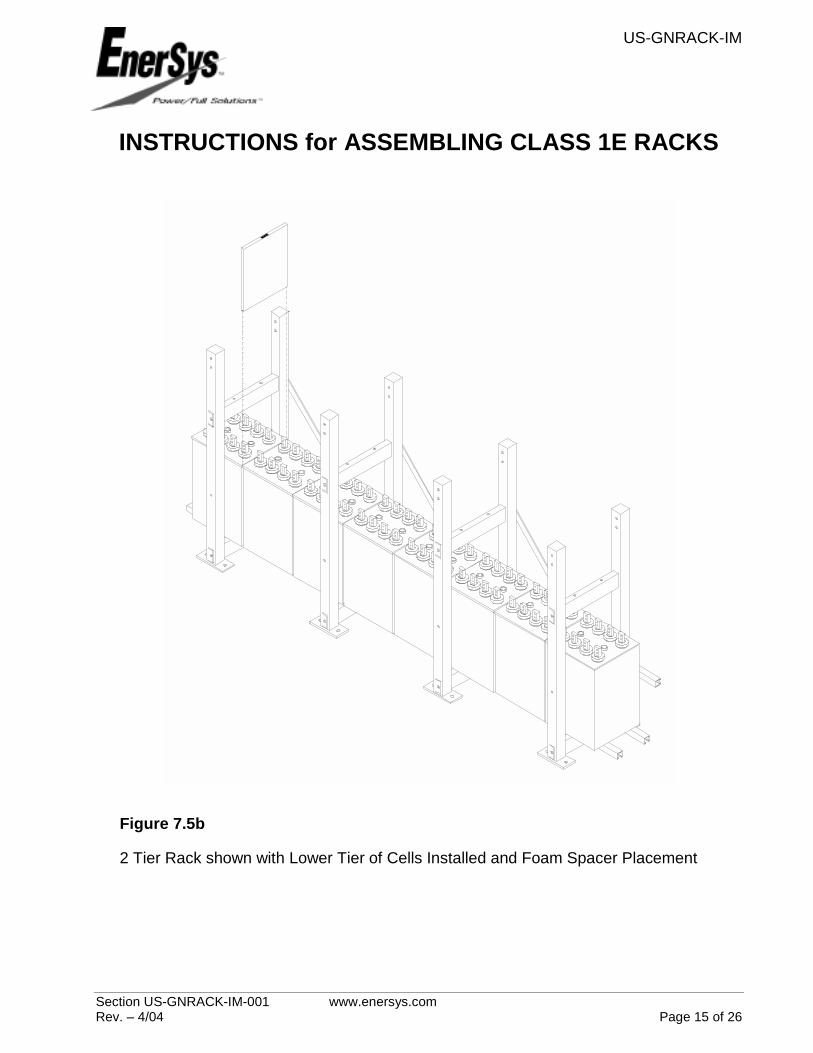
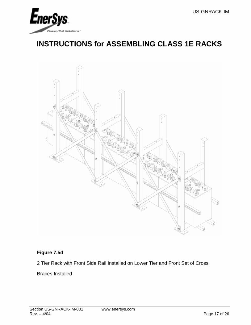
• Install cells on support rails, 2 tier racks should have the cells placed on the bottom tier first. The battery covers should be spaced approx. 0.38 in. (9.5 mm) apart to insure proper spacing for intercell connectors. See Figures 7.5a and 7.5b. After installing cells on the lower tier of a 2 tier rack, install front set of cross braces as instructed in Section 7.2. See Figure 7.5d.
• Foam spacers are to be installed between batteries where there is no cell clamp assembly. The black mark on the foam spacer edge should be facing the top of the cell. See Figures 7.5a and 7.5b.
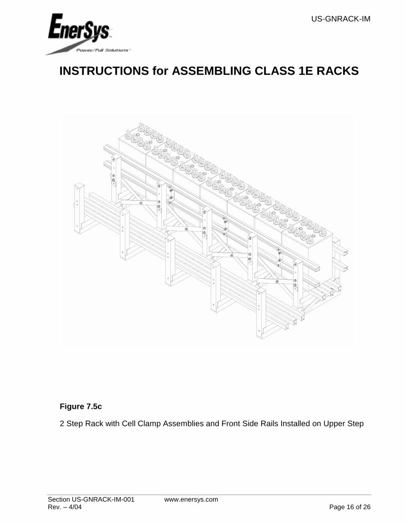
• Install cell clamp assemblies on 2 step rack. Verify cell clamp locations as shown on the rack assembly drawing. Attach cell clamps to side support rails. See Figure 7.5c. Refer to assembly drawing for hardware size and length. Torque per Table 1. WHEN TORQUING HEX NUTS ON THREADED ROD, USE CAUTION TO AVOID BENDING CELL CLAMP PLATES AGAINST BATTERY JARS. HOLD HEX NUT BETWEEN PLATES STATIONARY AND
TORQUE THE HEX NUT ON THE OUTSIDE OF THE ASSEMBLY.
• Attach plastic channel to front side rail(s) per Section 7.4 and install front side rail(s) as instructed in Section 7.3. See Figures 7.5c and 7.5d. Install shim(s) as necessary between side rails and rack frame to ensure proper side rail fit with battery jars. See to Figure 7.3c. The side rail bolts may need to be loosened to perform this step, be sure to re-torque per Table 1 when complete.
• Install cells on next step/tier following the methods as instructed for the first tier/step. See Figures 7.5e through 7.5k.
7.6 END RAIL AND CORNER BRACKET ASSEMBLY
The location of the corner brackets is determined when the batteries are evenly spaced on the rack.
• Attach plastic channels to end rails per section 7.4.
• Two Step racks have left/right long and short corner brackets, use the bracket that fits around the frame members best. Refer to assembly drawing for hardware size and length. See Figure 7.6a.
• Two Tier racks have left/right corner brackets which assemble with a blocker plate. Refer to assembly drawing for hardware size and length. See Figure 7.6b.
• Determine the location of each corner bracket and loosely fasten in place.
• Slide end rail into place.
• Torque per Table 1.
US-GNRACK-IM
Section US-GNRACK-IM-001 www.enersys.com Rev. – 4/04 Page 5 of 26
INSTRUCTIONS for ASSEMBLING CLASS 1E RACKS GLOSSARY OF TERMS
2S RACK Rack with one row of batteries located behind another row of batteries with the back row slightly elevated above the front row of batteries.
2T RACK Rack with one row of batteries located directly above another row of batteries.
CELL CLAMP ASSEMBLY Brackets and threaded rod assembly connected to side rails and positioned between battery jars to help reduce lateral battery movement during a seismic event.
CORNER BRACKET ASSEMBLY Bracket assembly (left & right, long & short) used to attach end rail to side rails to prevent batteries from falling off rack during a seismic event.
CROSS BRACE Steel brace used to connect rack frames together.
END RAIL Rail attached to corner brackets to prevent batteries from falling off rack during a seismic event.
EPA Environmental Protection Agency
FOAM SPACER Spacers used to prevent batteries from hitting each other during a seismic event.
FRAME Main steel support structure of battery rack.
INTERCELL CONNECTOR Electrical conductors used to connect adjacent cells on the same tier of a rack.
INTEGRATED SYSTEMS & SERVICE (IS&S) EnerSys’ service and installation group.
NEC National Electric Code
OSHA Occupational Safety & Health Administration
SIDE RAIL Rails used to prevent cells from falling off rack during a seismic event.
SHIM Thin metal spacers used to bring side rails close to battery or to level rack due to uneven flooring.
SPACER Steel spacers that may be required for certain battery models on certain battery racks to move the side rails closer to the battery jar for optimum seismic protection.
SUPPORT RAIL Rails connected to the frame that supports the batteries.
US-GNRACK-IM
Section US-GNRACK-IM-001 www.enersys.com Rev. – 4/04 Page 6 of 26
INSTRUCTIONS for ASSEMBLING CLASS 1E RACKS
Figure 7.1a
Typical 2 Step Frame Weldment
Figure 7.1b
Typical 2 Tier Frame Weldment

US-GNRACK-IM
Section US-GNRACK-IM-001 www.enersys.com Rev. – 4/04 Page 7 of 26
INSTRUCTIONS for ASSEMBLING CLASS 1E RACKS
Figure 7.2a
2 Step Rack with rear two sets of Cross Braces Installed
US-GNRACK-IM
Section US-GNRACK-IM-001 www.enersys.com Rev. – 4/04 Page 8 of 26
INSTRUCTIONS for ASSEMBLING CLASS 1E RACKS
Figure 7.2b
2 Tier Rack with rear set of Cross Braces Installed
US-GNRACK-IM
Section US-GNRACK-IM-001 www.enersys.com Rev. – 4/04 Page 9 of 26
INSTRUCTIONS for ASSEMBLING CLASS 1E RACKS
Figure 7.3a
2 Step Rack with Support Rails and Rear Set of Side Rails Installed for Upper Step.

US-GNRACK-IM
Section US-GNRACK-IM-001 www.enersys.com Rev. – 4/04 Page 10 of 26
INSTRUCTIONS for ASSEMBLING CLASS 1E RACKS
Figure 7.3b
2 Tier Rack with Lower Support Rails and Rear Side Rail Installed for Lower Tier
US-GNRACK-IM
Section US-GNRACK-IM-001 www.enersys.com Rev. – 4/04 Page 11 of 26
INSTRUCTIONS for ASSEMBLING CLASS 1E RACKS
SPACER
SHIM
Figure 7.3c
Typical Side Rail to Frame Assembly with Spacer and Shim Placement Shown, when
applicable
US-GNRACK-IM
Section US-GNRACK-IM-001 www.enersys.com Rev. – 4/04 Page 12 of 26
INSTRUCTIONS for ASSEMBLING CLASS 1E RACKS
Figure 7.3d Step 1 Figure 7.3d Step 2
Figure 7.3d Step 3 Figure 7.3d Step 4
US-GNRACK-IM
Section US-GNRACK-IM-001 www.enersys.com Rev. – 4/04 Page 13 of 26
INSTRUCTIONS for ASSEMBLING CLASS 1E RACKS
PLASTIC CHANNEL
DOUBLE-SIDED TAPE
UNISTRUT RAIL
Figure 7.4
Typical Rail and Plastic Channel Assembly
US-GNRACK-IM
Section US-GNRACK-IM-001 www.enersys.com Rev. – 4/04 Page 14 of 26
INSTRUCTIONS for ASSEMBLING CLASS 1E RACKS
Figure 7.5a
2 Step Rack shown with Rear Row of Cells Installed with Cell Clamp Assemblies and
Foam Spacer Placement
US-GNRACK-IM
Section US-GNRACK-IM-001 www.enersys.com Rev. – 4/04 Page 15 of 26
INSTRUCTIONS for ASSEMBLING CLASS 1E RACKS
Figure 7.5b
2 Tier Rack shown with Lower Tier of Cells Installed and Foam Spacer Placement
US-GNRACK-IM
Section US-GNRACK-IM-001 www.enersys.com Rev. – 4/04 Page 16 of 26
INSTRUCTIONS for ASSEMBLING CLASS 1E RACKS
Figure 7.5c
2 Step Rack with Cell Clamp Assemblies and Front Side Rails Installed on Upper Step
US-GNRACK-IM
Section US-GNRACK-IM-001 www.enersys.com Rev. – 4/04 Page 17 of 26
INSTRUCTIONS for ASSEMBLING CLASS 1E RACKS
Figure 7.5d
2 Tier Rack with Front Side Rail Installed on Lower Tier and Front Set of Cross
Braces Installed
US-GNRACK-IM
Section US-GNRACK-IM-001 www.enersys.com Rev. – 4/04 Page 18 of 26
INSTRUCTIONS for ASSEMBLING CLASS 1E RACKS
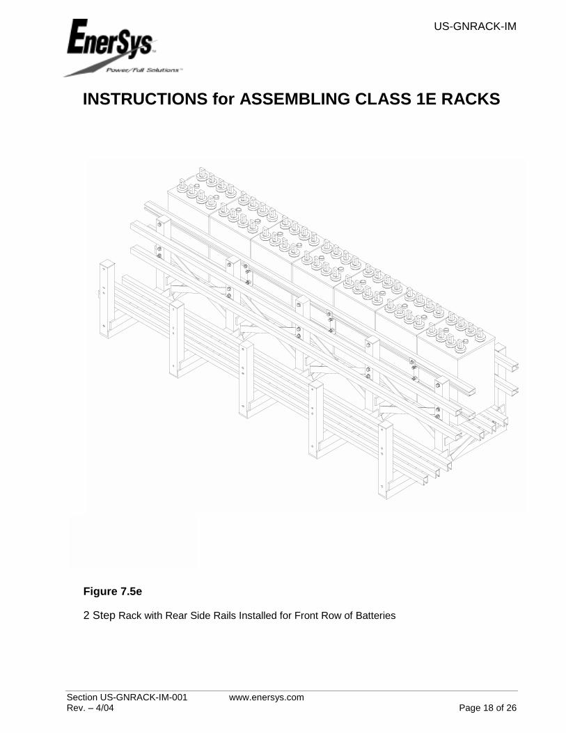
Figure 7.5e
2 Step Rack with Rear Side Rails Installed for Front Row of Batteries
US-GNRACK-IM
Section US-GNRACK-IM-001 www.enersys.com Rev. – 4/04 Page 19 of 26
INSTRUCTIONS for ASSEMBLING CLASS 1E RACKS
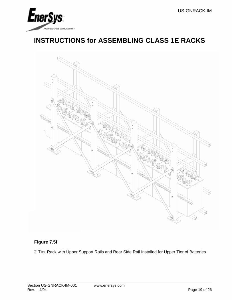
Figure 7.5f
2 Tier Rack with Upper Support Rails and Rear Side Rail Installed for Upper Tier of Batteries
US-GNRACK-IM
Section US-GNRACK-IM-001 www.enersys.com Rev. – 4/04 Page 20 of 26
INSTRUCTIONS for ASSEMBLING CLASS 1E RACKS
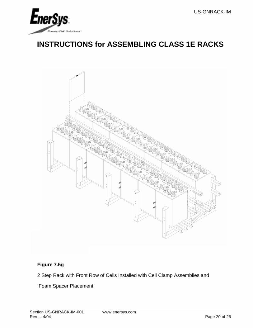
Figure 7.5g
2 Step Rack with Front Row of Cells Installed with Cell Clamp Assemblies and
Foam Spacer Placement
US-GNRACK-IM
Section US-GNRACK-IM-001 www.enersys.com Rev. – 4/04 Page 21 of 26
INSTRUCTIONS for ASSEMBLING CLASS 1E RACKS
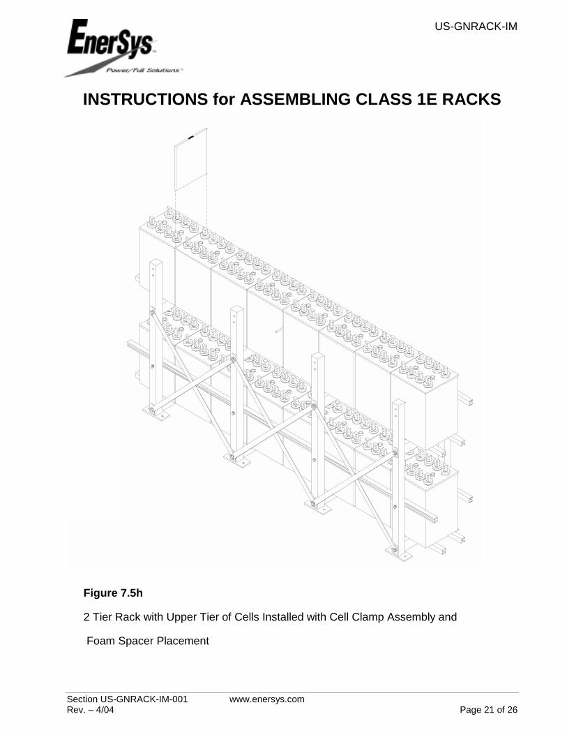
Figure 7.5h
2 Tier Rack with Upper Tier of Cells Installed with Cell Clamp Assembly and
Foam Spacer Placement
US-GNRACK-IM
Section US-GNRACK-IM-001 www.enersys.com Rev. – 4/04 Page 22 of 26
INSTRUCTIONS for ASSEMBLING CLASS 1E RACKS
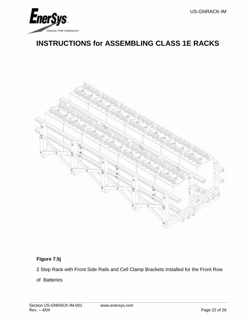
Figure 7.5j
2 Step Rack with Front Side Rails and Cell Clamp Brackets Installed for the Front Row
of Batteries

US-GNRACK-IM
Section US-GNRACK-IM-001 www.enersys.com Rev. – 4/04 Page 23 of 26
INSTRUCTIONS for ASSEMBLING CLASS 1E RACKS
Figure 7.5k
2 Tier Rack with Front Side Rail and Cell Clamp Brackets Installed for the Upper Tier of
Batteries
US-GNRACK-IM
Section US-GNRACK-IM-001 www.enersys.com Rev. – 4/04 Page 24 of 26
INSTRUCTIONS for ASSEMBLING CLASS 1E RACKS
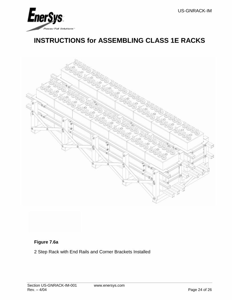
Figure 7.6a
2 Step Rack with End Rails and Corner Brackets Installed
US-GNRACK-IM
Section US-GNRACK-IM-001 www.enersys.com Rev. – 4/04 Page 25 of 26
INSTRUCTIONS for ASSEMBLING CLASS 1E RACKS
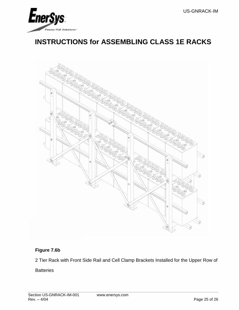
Figure 7.6b
2 Tier Rack with Front Side Rail and Cell Clamp Brackets Installed for the Upper Row of
Batteries

Publication No: US-GNRACK-IM-001 April 2004
EnerSys EMEA Brussels, Belgium Tel: +32 (0)2 247 94 47 EnerSys Asia Guangdong, China
www.enersys.com
Subject to revisions without prior notice.
EnerSys P.O. Box 14145 Reading, PA 19612-4145 USA Tel: +1-610-208-1991
Tel: +86 755 2689 3639 Printed in USA