Embed Size (px)
Citation preview
Instructions-Parts
SaniForce™ Pneumatic Controls3A6101B
EN
Integrated Pneumatic Controls for use with Hygienic Unloader Systems. For professional use only.
Important Safety InstructionsRead all warnings and instructions in this manual and the systemmanuals. Save all instructions.
Maximum Working Air Pressure: 100psi (0.7 MPa, 6.9 bar)
PROVEN QUALITY. LEADING TECHNOLOGY.
Contents
Models............................................................... 2
Pressure Relief Procedure .................................. 3
Switch Replacement ........................................... 5
25C578 Parts ..................................................... 6
25C543 Parts ..................................................... 14
Models
ModelNumber
Description
25C578 Pneumatic control panel, STU
25C543 Pneumatic control panel, SDU
2 3A6101B
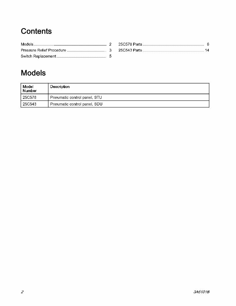
Pressure Relief Procedure
Pressure Relief Procedure
Follow the Pressure Relief Procedurewhenever you see this symbol.
1. Follow the Pressure Relief Procedure in thesystem operation manual where this controlpanel is installed to place the system in a safemaintenance position before servicing theequipment.
2. Turn off air supply valves, BV1 & BV2, locatedon the bottom of the control panel.
This equipment stays pressurized until pressure isrelieved manually. To help prevent serious injury frominjection, pinching, or crushing, follow the PressureRelief Procedure before you clean, check, or servicethe equipment.
3A6101B 3

Notes
Notes
4 3A6101B
Switch Replacement
Switch Replacement
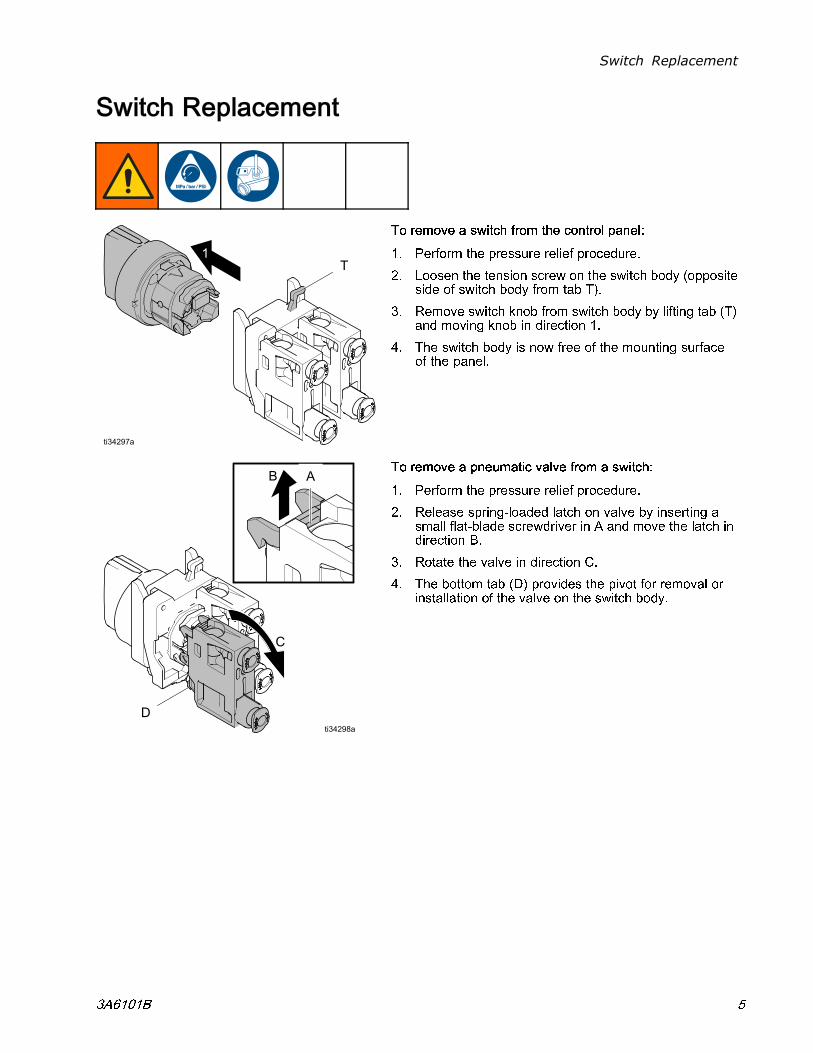
To remove a switch from the control panel:
1. Perform the pressure relief procedure.
2. Loosen the tension screw on the switch body (oppositeside of switch body from tab T).
3. Remove switch knob from switch body by lifting tab (T)and moving knob in direction 1.
4. The switch body is now free of the mounting surfaceof the panel.
To remove a pneumatic valve from a switch:
1. Perform the pressure relief procedure.
2. Release spring-loaded latch on valve by inserting asmall flat-blade screwdriver in A and move the latch indirection B.
3. Rotate the valve in direction C.
4. The bottom tab (D) provides the pivot for removal orinstallation of the valve on the switch body.
3A6101B 5
25C578 Parts
25C578 Parts
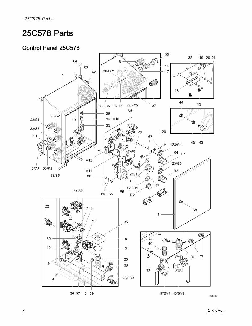
Control Panel 25C578
6 3A6101B
25C578 Parts
Control Panel 25C578
Ref. Part/Kit Description Qty.
1 17U557 ENCLOSURE 1
2 16V725 GAUGE, 0-30 psi 2
3 156593 O-RING, #222 1
4 16Y981 FITTING, bulkhead, 1/2 npt 1
5 C20195 O-RING, #213 1
6 16Y995 FITTING, bulkhead, 1/2 tube 4
7 100451 COUPLING 1
8 17S086 BLOCK, air control 1
9 114151 FITTING, elbow, swivel 6
10 114054 O-RING, #222 FMK 1
11 17T017 FITTING, elbow, 3/8T x 3/8stem
1
12 16G247 FITTING, 1/2 npt x 3/8 tube 1
13 17T272 SCREW, seal 14
14 191586 FITTING, 3/8 npt 3
15 113348 WASHER, lock 3
16 111014 NUT, jam 3
17 17V668 WASHER 3
18 17T271 HINGE 2
19 102360 WASHER, flat 4
20 100020 WASHER, lock 4
21 104371 SCREW, 10 x 0.375 4
22 17W584 SWITCH, 3 position 3
23 17W582 BUTTON, push 2
26 17S085 FITTING, 3/4 npt x 4 5/8 1
27 17P903 BULKHEAD 3
28 17T098 VALVE 3/8 npt x 3/8 tube 4
29 114485 FITTING 1
30 17T103 FITTING 4
32 109478 NUT 4
33 124844 FITTING tee 1
34 17S738 NOZZLE 1
35 154662 O-RING 1
36 17S087 MANIFOLD 1
37 114263 FITTING 1
38 15V204 FITTING, elbow, 1/2 npt x 1/2tube
1
Ref. Part/Kit Description Qty.
39 101754 PLUG 2
40 114373 FITTING, nipple 1
43 17T520 LATCH, 1/4 turn 1
44 17T523 RETAINER, 1/4 turn 1
45 17T524 SPRING, 1/4 turn 1
47 16Y861 VALVE, ball, vented, 1/2 in. 1
48 17T519 VALVE, ball, vented, 3/4 in. 1
49 C38211 FITTING, tube 1
51 123988 FITTING, 1/2 x 3/8 tube 1
52 17V624 FITTING, tee 2
53 17V626 FITTING, tee 1
54 17V625 FITTING 2
55 17Y406* TUBE, 3/8 O.D. 6 ft
56 17Y407* TUBE, 1/2 O.D. 15 ft
57 17Y408* TUBE, 0.156 O.D. 6 ft
58 113281 VALVE, OR gate 3
59 17A251 FITTING, reducer, 1/4 to 5/32 1
60 617569 FITTING, reducer 1
61 17T422 BRACKET, foot, pack of 4 1
62 102471 SCREW, 3/8-16 x 1.0 4
63 104034 WASHER 4
64 17T873 SPACER, 3/8 x 0.5 4
65 101566 NUT 4
66 100023 WASHER 4
67 17W450 LABEL SET 1
68 17U123 KEY, latch 1
69 17W585 BLOCK, mounting 5
70 17W586 VALVE, switch 8
72 17A240 FITTING, elbow, 5/32 8
80 — — — PANEL, air controls, see page8
1
120 — — — PANEL, component, see page10
1
* Part number represents a 6 foot length ofreplacement tube.
3A6101B 7
25C578 Parts
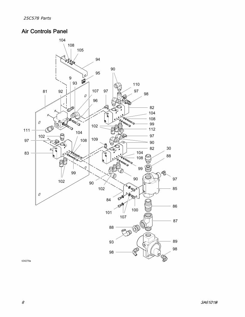
Air Controls Panel
8 3A6101B
25C578 Parts
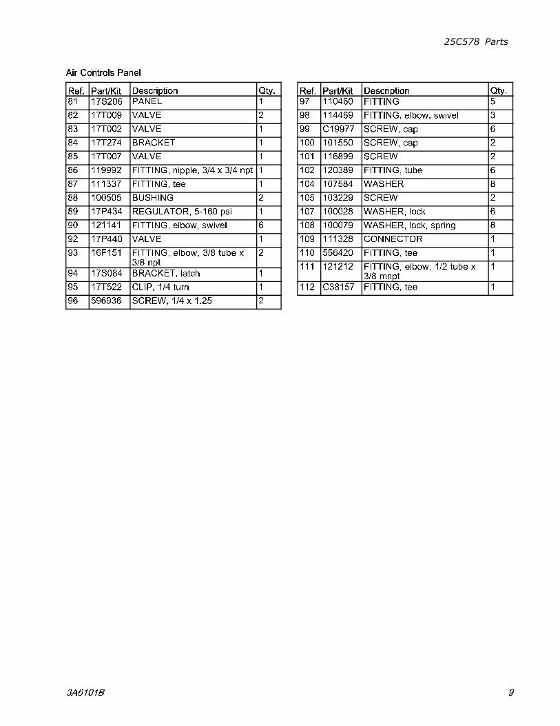
Air Controls Panel
Ref. Part/Kit Description Qty.
81 17S206 PANEL 1
82 17T009 VALVE 2
83 17T002 VALVE 1
84 17T274 BRACKET 1
85 17T007 VALVE 1
86 119992 FITTING, nipple, 3/4 x 3/4 npt 1
87 111337 FITTING, tee 1
88 100505 BUSHING 2
89 17P434 REGULATOR, 5-160 psi 1
90 121141 FITTING, elbow, swivel 6
92 17P440 VALVE 1
93 16F151 FITTING, elbow, 3/8 tube x3/8 npt
2
94 17S084 BRACKET, latch 1
95 17T522 CLIP, 1/4 turn 1
96 596936 SCREW, 1/4 x 1.25 2
Ref. Part/Kit Description Qty.
97 110460 FITTING 5
98 114469 FITTING, elbow, swivel 3
99 C19977 SCREW, cap 6
100 101550 SCREW, cap 2
101 116899 SCREW 2
102 120389 FITTING, tube 6
104 107584 WASHER 8
105 103229 SCREW 2
107 100028 WASHER, lock 6
108 100079 WASHER, lock, spring 8
109 111328 CONNECTOR 1
110 556420 FITTING, tee 1
111 121212 FITTING, elbow, 1/2 tube x3/8 mnpt
1
112 C38157 FITTING, tee 1
3A6101B 9
25C578 Parts
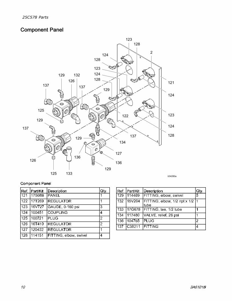
Component Panel
Component Panel
Ref. Part/Kit Description Qty.
121 17S088 PANEL 1
122 17T269 REGULATOR 1
123 16V727 GAUGE, 0-160 psi 3
124 100451 COUPLING 4
125 100721 PLUG 2
126 16T410 REGULATOR 2
127 120432 REGULATOR 1
128 114151 FITTING, elbow, swivel 4
Ref. Part/Kit Description Qty.
129 114469 FITTING, elbow, swivel 5
132 15V204 FITTING, elbow, 1/2 npt x 1/2tube
1
133 17G678 FITTING, tee, 1/2 tube 1
134 117480 VALVE, relief, 26 psi 1
136 104765 PLUG 2
137 C38211 FITTING 4
10 3A6101B
25C578 Parts
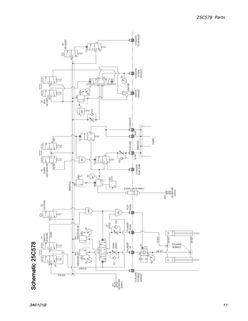
Schematic25C578
3 A 6 1 0 1 B 1 1
25C578 Parts
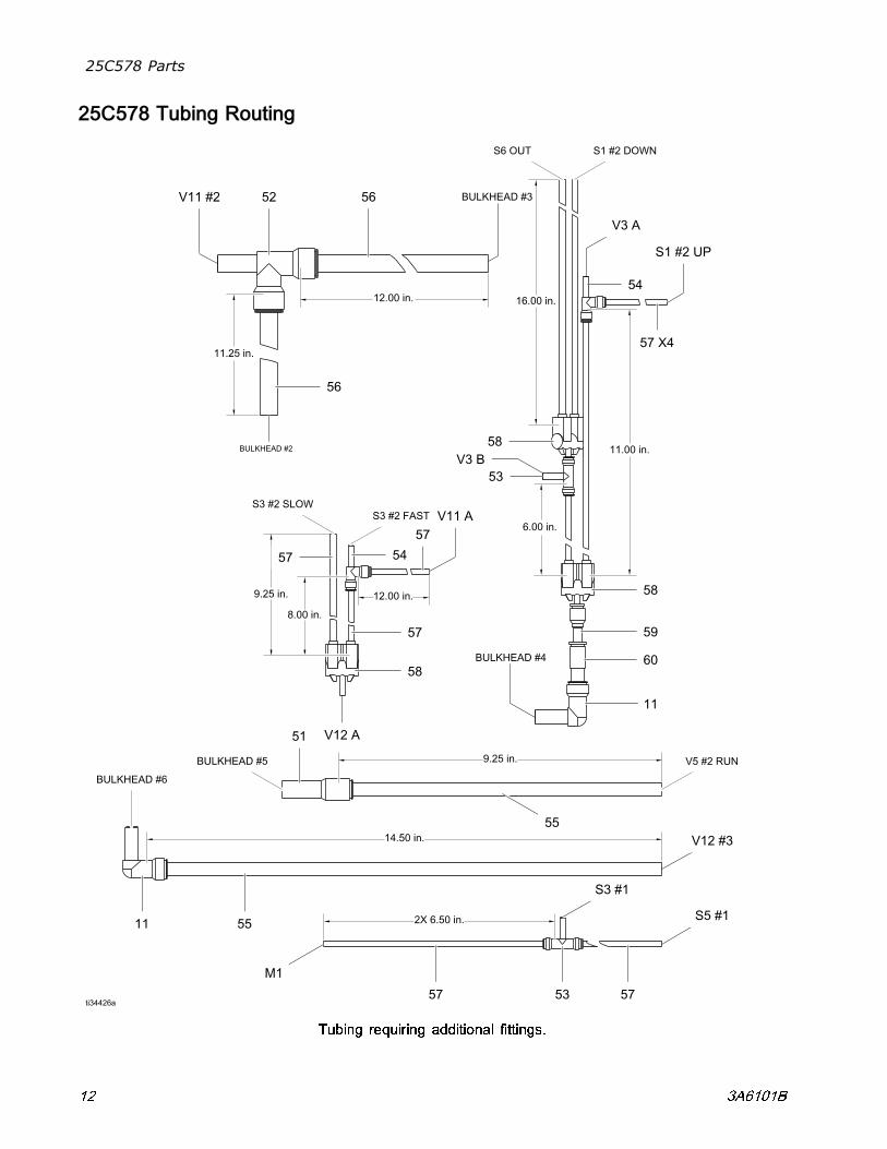
25C578 Tubing Routing
Tubing requiring additional fittings.
12 3A6101B
25C578 Parts
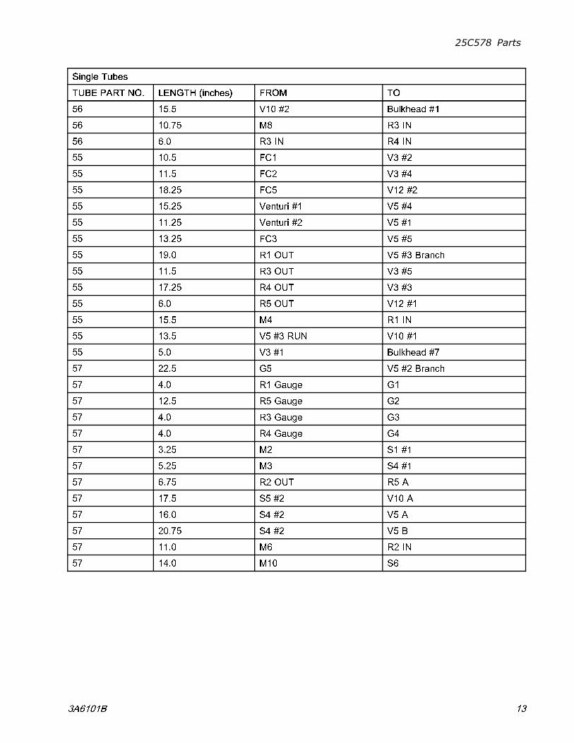
Single Tubes
TUBE PART NO. LENGTH (inches) FROM TO
56 15.5 V10 #2 Bulkhead #1
56 10.75 M8 R3 IN
56 6.0 R3 IN R4 IN
55 10.5 FC1 V3 #2
55 11.5 FC2 V3 #4
55 18.25 FC5 V12 #2
55 15.25 Venturi #1 V5 #4
55 11.25 Venturi #2 V5 #1
55 13.25 FC3 V5 #5
55 19.0 R1 OUT V5 #3 Branch
55 11.5 R3 OUT V3 #5
55 17.25 R4 OUT V3 #3
55 6.0 R5 OUT V12 #1
55 15.5 M4 R1 IN
55 13.5 V5 #3 RUN V10 #1
55 5.0 V3 #1 Bulkhead #7
57 22.5 G5 V5 #2 Branch
57 4.0 R1 Gauge G1
57 12.5 R5 Gauge G2
57 4.0 R3 Gauge G3
57 4.0 R4 Gauge G4
57 3.25 M2 S1 #1
57 5.25 M3 S4 #1
57 6.75 R2 OUT R5 A
57 17.5 S5 #2 V10 A
57 16.0 S4 #2 V5 A
57 20.75 S4 #2 V5 B
57 11.0 M6 R2 IN
57 14.0 M10 S6
3A6101B 13

25C543 Parts
25C543 Parts
Control Panel 25C543
Control Panel 25C578
14 3A6101B
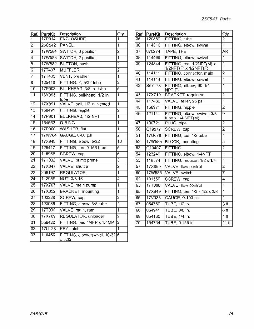
25C543 Parts
Ref. Part/Kit Description Qty.
1 17P914 ENCLOSURE 1
2 25C542 PANEL 1
3 17W584 SWITCH, 3 position 2
4 17W583 SWITCH, 2 position 1
5 17W582 BUTTON, push 2
6 17T407 MUFFLER 2
7 17T405 VENT, breather 1
8 125418 FITTING, Y, 5/32 tube 2
10 17P903 BULKHEAD, 3/8 in. tube 6
11 16Y995 FITTING, bulkhead, 1/2 in.tube
1
12 17X891 VALVE, ball, 1/2 in. vented 1
13 158491 FITTING, nipple 2
14 17P901 BULKHEAD, 1/2 NPT 1
15 154662 O-RING 1
16 17P900 WASHER, flat 1
17 17W764 GAUGE, 0-60 psi 2
18 17X848 FITTING, elbow, 5/32 10
19 125417 FITTING, tee, 0.156 tube 5
20 115968 SCREW, cap 6
21 17T002 VALVE, pump prime 3
22 17X847 VALVE, shuttle 2
23 206197 REGULATOR 1
24 112958 NUT, 3/8-16 4
25 17X707 VALVE, main pump 1
26 17X852 BRACKET, mounting 1
27 103229 SCREW, cap 2
28 123986 FITTING, elbow, 3/8 tube 4
29 17T009 VALVE, main, ram 1
30 17X709 REGULATOR, unloader 2
31 556420 FITTING, tee, 1/4FP x 1/4MP 2
32 17U123 KEY, latch 1
33 110460 FITTING, elbow, swivel, 10-32x 5.32
6
Ref. Part/Kit Description Qty.
35 120389 FITTING, tube 2
36 114316 FITTING, elbow, swivel 1
37 070274 TAPE, TFE AR
38 114469 FITTING, elbow, swivel 1
39 124844 FITTING, tee, 1/2NPT(M) x1/2NPT(F) x 1/2NPT(F)
1
40 114111 FITTING, connector, male 2
41 114114 FITTING, elbow, swivel 1
42 S67178 FITTING, elbow, 90 1/4NPT(F)
1
43 17X710 BRACKET, regulator 2
44 117480 VALVE, relief, 26 psi 1
45 156971 FITTING, nipple 2
46 121141 FITTING, elbow, swivel, 3/8tube x 1/4 NPT(M)
9
47 100721 PLUG, pipe 2
50 C19977 SCREW, cap 2
51 17G678 FITTING, tee, 1/2 tube 1
52 17W585 BLOCK, mounting 5
53 C19407 FITTING 2
54 123249 FITTING, elbow, 1/4NPT 1
55 118574 FITTING, reducer, 1/2 x 1/4 1
57 17X850 VALVE, flow control 2
60 17W586 VALVE, switch 7
62 101550 SCREW, cap 4
63 17T008 VALVE, flow control 1
65 17X849 FITTING, tee, 1/2 x 1/2 x 3/8 1
66 17V333 GAUGE, 0-100 psi 1
67 054760 TUBE, 1/2 in. 3 ft
68 054941 TUBE, 3/8 in. 6 ft
69 054130 TUBE, 1/4 in. 1 ft
70 154734 TUBE, 0.156 in. 11 ft
3A6101B 15
25C543 Parts
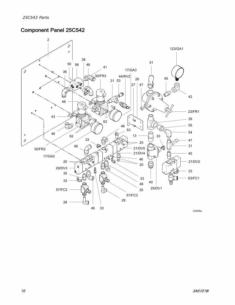
Component Panel 25C542
16 3A6101B
25C543 Parts
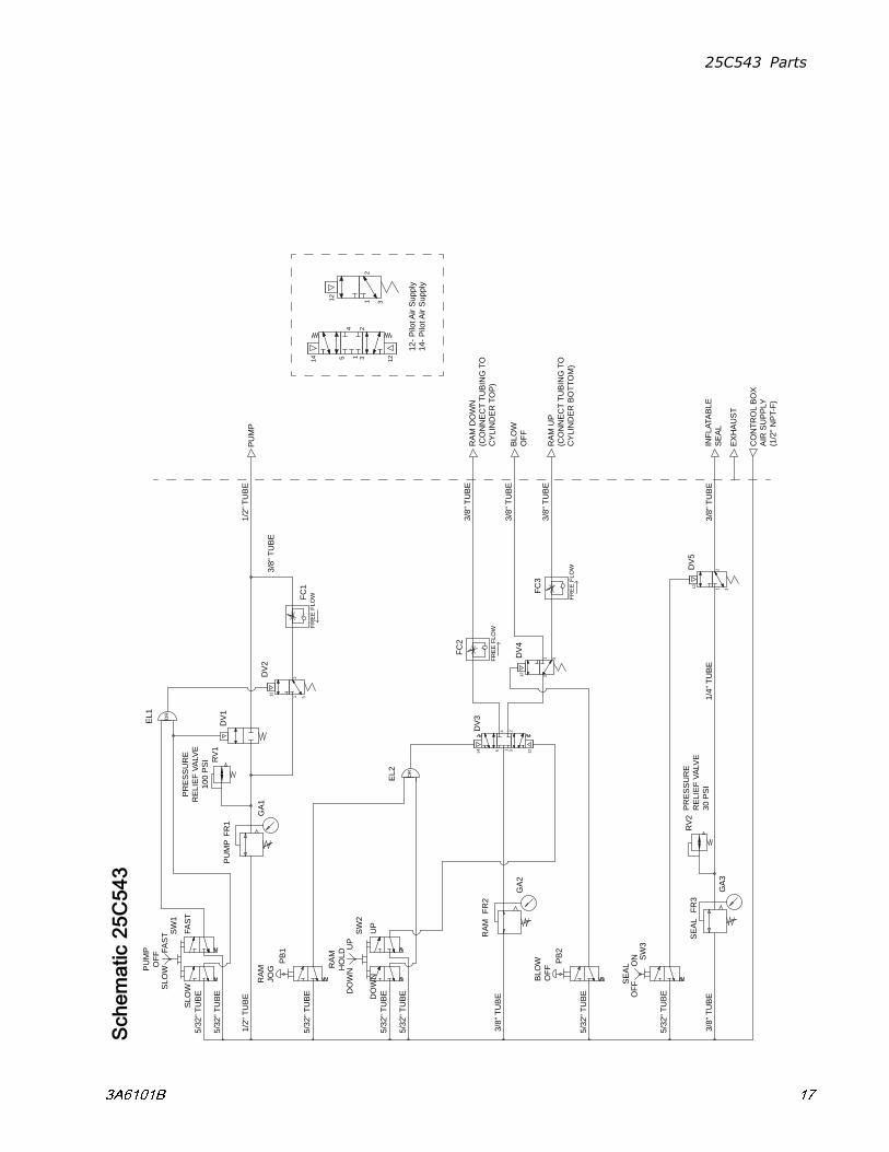
Schematic25C543
CO
NTR
OL
BO
XA
IR S
UP
PLY
(1/2
" NP
T-F)
PU
MP
OR
5/32
" TU
BE
5/32
" TU
BE
1/2"
TU
BE
1/2"
TU
BE
INFL
ATA
BLE
SE
AL
3/8"
TU
BE
1/4"
TU
BE
EX
HA
US
T
BLO
WO
FF
PR
ES
SU
RE
RE
LIE
F VA
LVE
30 P
SI
SE
AL
OFF
ON
3/8"
TU
BE
5/32
" TU
BE
5/32
" TU
BE
3/8"
TU
BE
3/8"
TU
BE
3/8"
TU
BE
RA
M U
P(C
ON
NE
CT
TUB
ING
TO
CY
LIN
DE
R B
OTT
OM
)
RA
M D
OW
N(C
ON
NE
CT
TUB
ING
TO
CY
LIN
DE
R T
OP
) 3/
8" T
UB
E
RA
MJO
G
5/32
" TU
BE
5/32
" TU
BE
5/32
" TU
BE
OR
PR
ES
SU
RE
RE
LIE
F VA
LVE
100
PS
I
BLO
WO
FF
3/8"
TU
BE
SW
1
FR1
GA
1
EL1
FC1
SW
3
FR3
GA
3
RV
2
FRE
E F
LOW
DV
1
DV
2
12- P
ilot A
ir S
uppl
y14
- Pilo
t Air
Sup
ply
14 1 354 2
1231
2
12
312
12
312
12
FR2
GA
2
DV
314 1 35
4 2
12
SW
2
PB
1
EL2
DV
5
RV
1
PB
2
FC2
FRE
E F
LOW
DV
4
31212
FC3
FRE
E F
LOW
PU
MP
OFF
SLO
WFA
ST FA
ST
SLO
W
PU
MP
SE
AL
RA
MH
OLD
DO
WN
UP
UP
DO
WN
RA
M
3 A 6 1 0 1 B 1 7
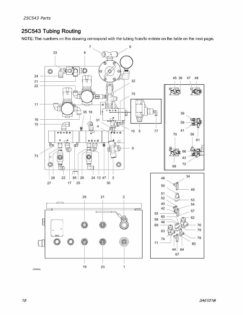
25C543 Parts
25C543 Tubing Routing
NOTE: The numbers on this drawing correspond with the tubing from/to entries on the table on the next page.
18 3A6101B
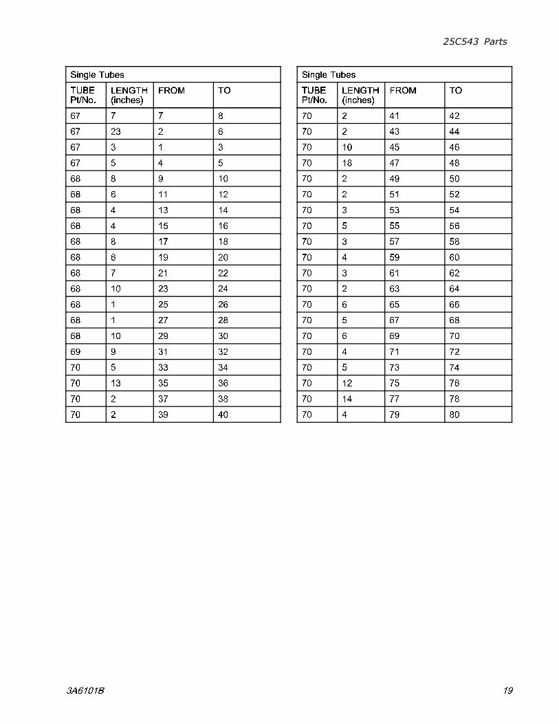
25C543 Parts
Single Tubes
TUBEPt/No.
LENGTH(inches)
FROM TO
67 7 7 8
67 23 2 6
67 3 1 3
67 5 4 5
68 8 9 10
68 6 11 12
68 4 13 14
68 4 15 16
68 8 17 18
68 6 19 20
68 7 21 22
68 10 23 24
68 1 25 26
68 1 27 28
68 10 29 30
69 9 31 32
70 5 33 34
70 13 35 36
70 2 37 38
70 2 39 40
Single Tubes
TUBEPt/No.
LENGTH(inches)
FROM TO
70 2 41 42
70 2 43 44
70 10 45 46
70 18 47 48
70 2 49 50
70 2 51 52
70 3 53 54
70 5 55 56
70 3 57 58
70 4 59 60
70 3 61 62
70 2 63 64
70 6 65 66
70 5 67 68
70 6 69 70
70 4 71 72
70 5 73 74
70 12 75 76
70 14 77 78
70 4 79 80
3A6101B 19
Graco Standard Warranty
Graco warrants all equipment referenced in this document which is manufactured by Graco and bearing itsname to be free from defects in material and workmanship on the date of sale to the original purchaser foruse. With the exception of any special, extended, or limited warranty published by Graco, Graco will, for aperiod of twelve months from the date of sale, repair or replace any part of the equipment determinedby Graco to be defective. This warranty applies only when the equipment is installed, operated andmaintained in accordance with Graco’s written recommendations.
This warranty does not cover, and Graco shall not be liable for general wear and tear, or any malfunction,damage or wear caused by faulty installation, misapplication, abrasion, corrosion, inadequate or impropermaintenance, negligence, accident, tampering, or substitution of non-Graco component parts. Nor shallGraco be liable for malfunction, damage or wear caused by the incompatibility of Graco equipmentwith structures, accessories, equipment or materials not supplied by Graco, or the improper design,manufacture, installation, operation or maintenance of structures, accessories, equipment or materialsnot supplied by Graco.
This warranty is conditioned upon the prepaid return of the equipment claimed to be defective to anauthorized Graco distributor for verification of the claimed defect. If the claimed defect is verified, Gracowill repair or replace free of charge any defective parts. The equipment will be returned to the originalpurchaser transportation prepaid. If inspection of the equipment does not disclose any defect in materialor workmanship, repairs will be made at a reasonable charge, which charges may include the costs ofparts, labor, and transportation.
THIS WARRANTY IS EXCLUSIVE, AND IS IN LIEU OF ANY OTHER WARRANTIES, EXPRESS ORIMPLIED, INCLUDING BUT NOT LIMITED TO WARRANTY OF MERCHANTABILITY OR WARRANTYOF FITNESS FOR A PARTICULAR PURPOSE.
Graco’s sole obligation and buyer’s sole remedy for any breach of warranty shall be as set forth above.The buyer agrees that no other remedy (including, but not limited to, incidental or consequential damagesfor lost profits, lost sales, injury to person or property, or any other incidental or consequential loss) shallbe available. Any action for breach of warranty must be brought within two (2) years of the date of sale.
GRACO MAKES NO WARRANTY, AND DISCLAIMS ALL IMPLIED WARRANTIES OFMERCHANTABILITY AND FITNESS FOR A PARTICULAR PURPOSE, IN CONNECTION WITHACCESSORIES, EQUIPMENT, MATERIALS OR COMPONENTS SOLD BUT NOT MANUFACTURED BYGRACO. These items sold, but not manufactured by Graco (such as electric motors, switches, hose, etc.),are subject to the warranty, if any, of their manufacturer. Graco will provide purchaser with reasonableassistance in making any claim for breach of these warranties.
In no event will Graco be liable for indirect, incidental, special or consequential damages resulting fromGraco supplying equipment hereunder, or the furnishing, performance, or use of any products or othergoods sold hereto, whether due to a breach of contract, breach of warranty, the negligence of Graco, orotherwise.
FOR GRACO CANADA CUSTOMERS
The Parties acknowledge that they have required that the present document, as well as all documents,notices and legal proceedings entered into, given or instituted pursuant hereto or relating directly orindirectly hereto, be drawn up in English. Les parties reconnaissent avoir convenu que la rédaction duprésente document sera en Anglais, ainsi que tous documents, avis et procédures judiciaires exécutés,donnés ou intentés, à la suite de ou en rapport, directement ou indirectement, avec les procéduresconcernées.
Graco Information
For the latest information about Graco products, visit www.graco.com.For patent information, see www.graco.com/patents.
To place an order, contact your Graco Distributor or call to identify the nearest distributor.
Phone: 612-623-6921 or Toll Free: 1-800-328-0211 Fax: 612-378-3505
All written and visual data contained in this document reflects the latest product information available at the time of publication.Graco reserves the right to make changes at any time without notice.
Original Instructions. This manual contains English. MM 3A6101
Graco Headquarters: MinneapolisInternational Offices: Belgium, China, Japan, Korea
GRACO INC. AND SUBSIDIARIES • P.O. BOX 1441 • MINNEAPOLIS MN 55440-1441 • USACopyright 2018, Graco Inc. All Graco manufacturing locations are registered to ISO 9001.
www.graco.comRevision B, January 2019