Embed Size (px)
Citation preview

The range of oil free and oil injected screw compressor models offered by RJ Engineering is
supplemented by a full selection of desiccant bed based dryer packages. The custom built
air dryers utilize activated alumina or molecular sieve as the desiccant. Process conditions
and dew point requirements decide the desiccant material, size and shape.
Natural Gas dryers or dehydration units are custom built for low pressure gas flows or very
low water dew point requirements. Gas dryers use primarily molecular sieve beds, with the
selection depending on the process conditions. Natural gas dryer packages are integrated
units with separators, regeneration heaters, coolers and separators. The package will have
pressure boosters and after coolers as well, when utilizing dry gas for regeneration.
Packages are designed and built to customer requirements, conforming to industry
standards and functional specifications.
Custom Engineered Solutions
RJ ENGINEERING SYSTEMS, INC
Desiccant Dryer Packages Instrument Air & Process Gas

The flexibility afforded by wide selection of the desiccant media and particle size used in the dryer
beds allows design and building of packages that can handle a large spectrum of operating
conditions.
When wet gas /air contacts solid desiccant particles, water is absorbed by the bed till equilibrium
is established between the water content in the gas stream and in the desiccant particles. The
equilibrium can be represented as isotherms (constant temperature), isobars (constant partial
pressure of water vapor) and isosteres (constant water content in the desiccant), across the
common desiccant types—Activated Alumina, Silica Gel and Molecular Sieve, to predict capacities
and performance at the desired process conditions.
Based on the primary variable of contact temperature of the gas to be dried, desiccant type is
selected considering the static capacity or water vapor absorption isobar of the desiccant. The
desired product dew point decides the final selection of desiccant particle size based on the
equilibrium isostere, with due consideration of gas velocities to avoid channeling of the gas or
fluidization of the bed.
Standard compressed air dryers using activated alumina have a recommended maximum
temperature limit of 60°C/140°F, where the static water absorption capacity reduces to 5% w/w.
The static capacities of Molecular sieve beds deteriorate to the same level only at about 130°
C/266°F, which makes it ideal for high temperature air and gas streams with low dew point
requirements.
Adsorption is a selective process for the desiccant media, with each gas or compound with its own
degree of adsorbability.
In compressed air service, the drying process is simplified due to the requirement primarily limited
to dehydration. In gas service, dryer system cycles can be carefully designed to remove recover
heavier hydrocarbons, as the process demands, along with dehydration. Special grades of
molecular sieves (sieve type 13X) can be used if the process demands sweetening and
dehydration of sour /acid gas.
Air dryer packages are custom manufactured in three categories:
Heatless Type: ADHL
Heated Blower Purge Type: ADBP
Heat of Compression Type: ADHC
The units are designed in pressure categories to match the discharge pressure limits and
temperature classes of the upstream compressors, as listed.
RJ ENGINEERING SYSTEMS, INC
Custom Engineered Solutions
Order of adsorbability
H2O CH3OH H2S CO2 C6+ C5 C4 C3 C2 C1
Fast > > > > > > > > Slow
Dehydration using Solid Desiccants –Technology:

Wet compressed air passes through a pre-filter and enters the pressurized online desiccant filled drying Tower A through valve XSV-1A. Valve
XSV-2A remains closed. Up-flow drying enables the desiccant to strip the air stream of moisture. Dry compressed air exits through the check
valve NRV-3A.
Tower B is depressurized to atmosphere through the purge valve XSV-2B with a down stream silencer, check valves NRV-3B and NRV-4A
remain closed . A portion of dry compressed air (purge air) is diverted before exiting 3A through a calibrated purge control valve PCV-5 and
check valve NRV-4B to Tower B desorbing the moisture from the desiccant bed top to bottom, and exits through valve XSV-2B. Purge pressure
is insufficient to open check valve NRV-3B, so it remains closed. Once the regeneration is complete, valve XSV-2B closes and Tower B is
re-pressurized . At tower switching, valve XSV-1B opens and XSV-1A closes, continuing drying of the stream. Check valves NRV-3A and NRV-4B
remain closed. Valve XSV-2A opens and Tower A is regenerated, repeating the process.
The tower shift interval is decided based on the dew point demanded as per ISO 8573.1 air quality class required. The purge pressure is
adjustable and is decided by the operating pressure and the ISO air quality dew point requirement. All the dryers also have the option of the
energy saving dew point demand cycle mode, which saves purge air by modulating the tower shift interval based on real time dew point
measurement.
RJ ENGINEERING SYSTEMS, INC
Custom Engineered Solutions
ADHL Series Heatless Desiccant Air Dryers-Process Description :
ADHL Series- Typical P&ID

These dryers do not have the compressed purge air loss present in heatless dryers. Wet compressed air passes through a pre-filter and enters
the pressurized online desiccant filled drying Tower A through valve XSV-1A. Valves XSV-2A, XSV-3A, XSV-1B and XSV-2B remain closed. Up-flow
drying enables the desiccant to strip the air stream of moisture. Dry compressed air exits through the check valve NRV-1A.
Tower B is depressurized to atmosphere through the purge valve XSV-3B with a down stream silencer. Check valves NRV-1B and NRV-2A
remain closed. Purge valve XSV-3B is closed once Tower B is depressurized. Valve XSV-2B opens and the heater is turned on. The high efficien-
cy blower draws in ambient air through a filter and feeds it through the heater through NRV-2B to tower B, desorbing the moisture from the
desiccant bed top to bottom, and exits through valve XSV-2B. The regeneration progress is monitored by the “temperature of absorption”
measured by the temperature transmitter at the bottom chamber of the desiccant bed. Once the regeneration is complete, the heater is
turned off and the bed cooled by ambient temperature air from the blower. After the cooling period, valve XSV-2B closes, XSV-1B opens and
Tower B is re-pressurized. After re-pressurization is complete, XSV-1B closes. At tower switching, valve XSV-1B opens and XSV-1A closes, con-
tinuing drying of the stream. Valve XSV-3A opens repeating the regeneration process on tower A.
The tower shift interval is decided based on the dew point demanded as per ISO 8573.1 air quality class required, which is measured at a
downstream dew point analyzer.. The heater temperature is an adjustable variable and is decided by the operating temperature range and the
desiccant selected.
RJ ENGINEERING SYSTEMS, INC
Custom Engineered Solutions
ADBP Series Heated Blower Purge Air Dryers-Process Description :
ADBP Series- Typical P&ID
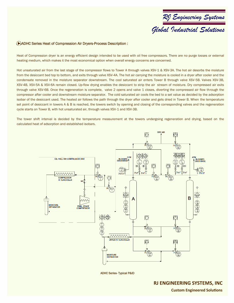
Heat of Compression dryer is an energy efficient design intended to be used with oil free compressors. There are no purge losses or external
heating medium, which makes it the most economical option when overall energy concerns are concerned.
Hot unsaturated air from the last stage of the compressor flows to Tower A through valves XSV-1 & XSV-3A. The hot air desorbs the moisture
from the desiccant bed top to bottom, and exits through valve XSV-4A. The hot air carrying the moisture is cooled in a dryer after cooler and the
condensate removed in the moisture separator downstream. The cool saturated air enters Tower B through valve XSV-5B. Valves XSV-3B,
XSV-4B, XSV-5A & XSV-6A remain closed. Up-flow drying enables the desiccant to strip the air stream of moisture. Dry compressed air exits
through valve XSV-6B. Once the regeneration is complete, valve 2 opens and valve 1 closes, diverting the compressed air flow through the
compressor after cooler and downstream moisture separator. The cold saturated air cools the bed to a set value as decided by the adsorption
isobar of the desiccant used. The heated air follows the path through the dryer after cooler and gets dried in Tower B. When the temperature
set point of desiccant in towers A & B is reached, the towers switch by opening and closing of the corresponding valves and the regeneration
cycle starts on Tower B, with hot unsaturated air, through valves XSV-1 and XSV-3B.
The tower shift interval is decided by the temperature measurement at the towers undergoing regeneration and drying, based on the
calculated heat of adsorption and established isobars.
RJ ENGINEERING SYSTEMS, INC
Custom Engineered Solutions
ADHC Series Heat of Compression Air Dryers-Process Description :
ADHC Series- Typical P&ID
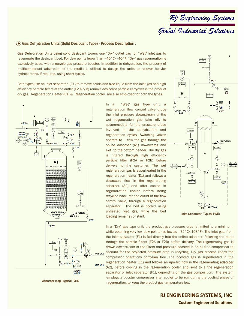
Gas Dehydration Units using solid desiccant towers use “Dry” outlet gas or “Wet” inlet gas to
regenerate the desiccant bed. For dew points lower than –40°C/ -40°F, “Dry” gas regeneration is
exclusively used, with a recycle gas pressure booster. In addition to dehydration, the property of
multicomponent adsorption of the media is utilized to design the units to recover heavier
hydrocarbons, if required, using short cycles.
Both types use an inlet separator (F1) to remove solids and free liquid from the inlet gas and high
efficiency particle filters at the outlet (F2 A & B) remove desiccant particle carryover in the product
dry gas. Regeneration Heater (E1) & Regeneration cooler are also employed for both the types.
In a “Wet” gas type unit, a
regeneration flow control valve drops
the inlet pressure downstream of the
wet regeneration gas take off, to
accommodate for the pressure drops
involved in the dehydration and
regeneration cycles. Switching valves
operate to flow the gas through the
online adsorber (A1) downwards and
exit to the bottom header. The dry gas
is filtered through high efficiency
particle filter (F2A or F2B) before
delivery to the customer. The wet
regeneration gas is superheated in the
regeneration heater (E1) and follows a
downward flow in the regenerating
adsorber (A2) and after cooled in
regeneration cooler before being
recycled back into the outlet of the flow
control valve, through a regeneration
separator. The bed is cooled using
unheated wet gas, while the bed
loading remains constant.
In a “Dry” gas type unit, the product gas pressure drop is limited to a minimum,
while obtaining very low dew points (as low as –75°C/-103°F). The inlet gas, from
the inlet separator (F1) is fed directly into the online adsorber, following the route
through the particle filters (F2A or F2B) before delivery. The regenerating gas is
drawn downstream of the filters and pressure boosted in an oil free compressor to
account for the projected pressure drop in recycling. Dry gas process keeps the
compressor operations corrosion free. The boosted gas is superheated in the
regeneration heater (E1) and follows an upward flow in the regenerating adsorber
(A2), before cooling in the regeneration cooler and sent to a the regeneration
separator or inlet separator (F1), depending on the gas composition. The system
employs a booster compressor after cooler to be run during the cooling phase of
regeneration, to keep the product gas temperature low.
RJ ENGINEERING SYSTEMS, INC
Custom Engineered Solutions
Gas Dehydration Units (Solid Desiccant Type) - Process Description :
Adsorber loop- Typical P&ID
Inlet Separator- Typical P&ID

Typical gas dehydration units of solid desiccant type employ
temperatures up to 290C/554F in bed regeneration. The
metallurgy and construction of the adsorber vessels, heaters,
regeneration cooler, piping and valves are carefully selected to
meet the demands of operating conditions and process media.
As a base rule, all materials conform to NACE MR 0175
requirements, with special requirements including austenitic
and duplex stainless steels and high grade nickel alloys
incorporated for aggressive process & ambient conditions and
operating environments. Heat treatment and NDE of the
equipment and piping components follow applicable ASME
codes and customer’s functional specifications, as applicable.
Valves are selected based on predicted number of cycles over the life of the unit. Metal
seated ball valves or high performance metal seated butterfly valves are employed for high
temperature and abrasive service, depending on operating pressures.
Electrical equipment,
s w i t c h g e a r a n d
instrumentation are
h aza rdous a r ea
classified to NEMA/
IEC/ATEX standards
depending on the
l o c a t i o n a n d
applicable rules.
System design and
construction are
adaptable to the
p h i l o s o p h y o f
operation of the plant,
with redundancy level
of equipment and
controls customized
to ensure non stop
operation.
Modeling of the adsorption system is based on experimental
information gathered from over 30 years of operation.
RJ ENGINEERING SYSTEMS, INC
Custom Engineered Solutions
Gas Dehydration Units (Solid Desiccant Type) - Construction :
Typical gas regeneration cycle– 8 hours
Particle Filters- Typical P&ID
Regeneration Heater/Booster after cooler- Typical P&ID

RJ ENGINEERING SYSTEMS, INC
Custom Engineered Solutions
Intelligent and Flexible Control Systems
Microprocessor based programmable control
systems with Graphic interfaces, with flexibility to
allow user programming and full remote
connectivity. Systems based on Programmable
Logic Controllers can integrate upstream and
downstream equipment for total package control, if
required. Standard construction has Stainless steel
panels- NEMA 4X/IP 66 protection with touchscreen
HMI. The HMIs have full onscreen diagnostic
capability and energy buffering for data security.
All panels are suitable for locating in harsh
environments, with basic units supplied with UL
Class 1 Div 2 or ATEX Zone 2 and 22 approvals.
SCR Controlled Heaters
Electric heaters used for blower purge air dryers and
regeneration gas in gas dehydration units use SCR
power controllers with dedicated heater panels, as
standard. The heater panels come standard with
safety features like Shorted SCR detection, Flange,
Element and Panel temperature cutouts. Standard
diagnostic features include individual Current,
Voltage and Power measurements, Partial load
detection and Earth leakage detection.
Gas Heaters typically use cartridge elements which
allow 100% redundancy.
Integrated Packages
Air dryers can be supplied as independent units or
integrated with upstream air compressors and storage
receivers. Heat of compression dryers can be
seamlessly integrated with the two stage dry screw air
compressors from RJ Engineering portfolio to make
compact packages.
Gas dehydration units are supplemented by oil free
pressure booster systems based on dry screw
compressors, oil free positive displacement blowers,
centrifugal compressors or non lubricated
reciprocating compressor packages, depending on
flow rate and operating pressure.
Features :
RJ ENGINEERING SYSTEMS, INC
Custom Engineered Solutions
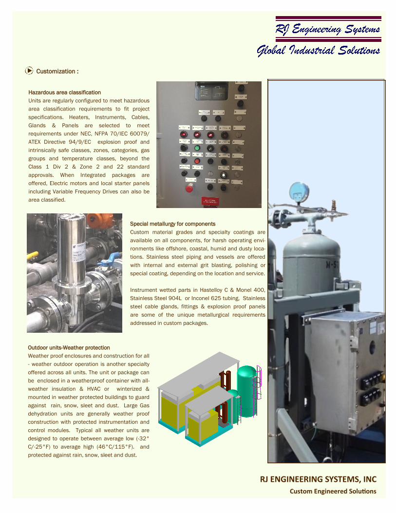
Hazardous area classification
Units are regularly configured to meet hazardous
area classification requirements to fit project
specifications. Heaters, Instruments, Cables,
Glands & Panels are selected to meet
requirements under NEC, NFPA 70/IEC 60079/
ATEX Directive 94/9/EC explosion proof and
intrinsically safe classes, zones, categories, gas
groups and temperature classes, beyond the
Class 1 Div 2 & Zone 2 and 22 standard
approvals. When Integrated packages are
offered, Electric motors and local starter panels
including Variable Frequency Drives can also be
area classified.
Outdoor units-Weather protection
Weather proof enclosures and construction for all
- weather outdoor operation is another specialty
offered across all units. The unit or package can
be enclosed in a weatherproof container with all-
weather insulation & HVAC or winterized &
mounted in weather protected buildings to guard
against rain, snow, sleet and dust. Large Gas
dehydration units are generally weather proof
construction with protected instrumentation and
control modules. Typical all weather units are
designed to operate between average low (-32°
C/-25°F) to average high (46°C/115°F). and
protected against rain, snow, sleet and dust.
Special metallurgy for components
Custom material grades and specialty coatings are
available on all components, for harsh operating envi-
ronments like offshore, coastal, humid and dusty loca-
tions. Stainless steel piping and vessels are offered
with internal and external grit blasting, polishing or
special coating, depending on the location and service.
Instrument wetted parts in Hastelloy C & Monel 400,
Stainless Steel 904L or Inconel 625 tubing, Stainless
steel cable glands, fittings & explosion proof panels
are some of the unique metallurgical requirements
addressed in custom packages.
Customization :

ADHL– Air Dryers: Heatless type
TECHNICAL SPECIFICATIONS—AIR DRYERS
RJ ENGINEERING SYSTEMS, INC
Custom Engineered Solutions
*Pressure dew points achievable to exceed ISO 8573.1 Class 1 levels. Purge rates depend on the ISO class selected and operating pressure. **Inlet flow capacities shown are at the nominal pressure; these are adjusted for higher inlet temperatures and higher or lower inlet pressures.
Model Number
Max Inlet Pressure Minimum Dew point
*
Inlet Flow Rate @ 37.8°C/
100°F ** Pressure Drop
Barg Psig Nm3/hr SCFM Bar Psi
LOW PRESSURE DRYERS (Nominal operating pressure: 10 Barg/ 145 Psig )
ADHL--L20 17.2 250 -100°F/-70°C 20 12.5 0.35 5
ADHL--L75 17.2 250 -100°F/-70°C 75 47 0.35 5
ADHL--L110 17.2 250 -100°F/-70°C 110 69 0.35 5
ADHL--L170 17.2 250 -100°F/-70°C 170 106 0.35 5
ADHL--L215 17.2 250 -100°F/-70°C 215 134 0.35 5
ADHL--L315 17.2 250 -100°F/-70°C 315 196 0.35 5
ADHL--L500 17.2 250 -100°F/-70°C 500 311 0.35 5
ADHL--L700 17.2 250 -100°F/-70°C 700 435 0.35 5
ADHL--L850 17.2 250 -100°F/-70°C 850 529 0.35 5
ADHL--L1100 17.2 250 -100°F/-70°C 1100 684 0.35 5
ADHL--L1400 17.2 250 -100°F/-70°C 1400 870 0.35 5
ADHL--L1750 17.2 250 -100°F/-70°C 1750 1088 0.35 5
ADHL--L2150 17.2 250 -100°F/-70°C 2150 1337 0.35 5
ADHL--L2500 17.2 250 -100°F/-70°C 2500 1555 0.35 5
ADHL--L3000 17.2 250 -100°F/-70°C 3000 1866 0.35 5
ADHL--L4000 17.2 250 -100°F/-70°C 4000 2488 0.35 5
ADHL--L5700 17.2 250 100°F/-70°C 5700 3545 0.35 5
ADHL--L7800 17.2 250 -100°F/-70°C 7800 4851 0.35 5
ADHL--L10000 17.2 250 -100°F/-70°C 10000 6220 0.35 5
HIGH PRESSURE DRYERS (Nominal operating pressure: 24 Barg/ 348 Psig )
ADHL--H50 34.5 500 -100°F/-70°C 50 31 0.7 10
ADHL--H100 34.5 500 -100°F/-70°C 100 62 0.7 10
ADHL--H200 34.5 500 -100°F/-70°C 200 125 0.7 10
ADHL--H400 34.5 500 -100°F/-70°C 400 249 0.7 10
ADHL--H600 34.5 500 -100°F/-70°C 600 373 0.7 10
ADHL--H900 34.5 500 -100°F/-70°C 900 560 0.7 10
ADHL--H1500 34.5 500 -100°F/-70°C 1500 933 0.7 10
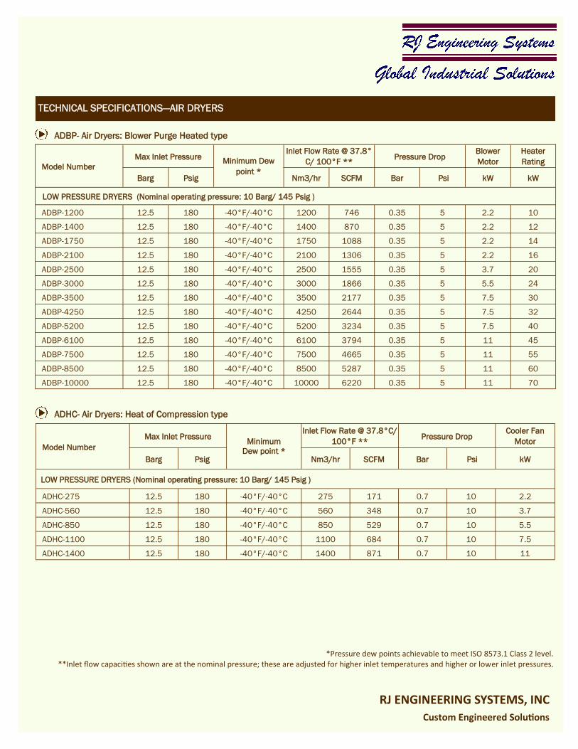
ADBP- Air Dryers: Blower Purge Heated type
TECHNICAL SPECIFICATIONS—AIR DRYERS
RJ ENGINEERING SYSTEMS, INC
Custom Engineered Solutions
*Pressure dew points achievable to meet ISO 8573.1 Class 2 level. **Inlet flow capacities shown are at the nominal pressure; these are adjusted for higher inlet temperatures and higher or lower inlet pressures.
ADHC- Air Dryers: Heat of Compression type
Model Number
Max Inlet Pressure Minimum Dew
point *
Inlet Flow Rate @ 37.8°
C/ 100°F ** Pressure Drop
Blower
Motor
Heater
Rating
Barg Psig Nm3/hr SCFM Bar Psi kW kW
LOW PRESSURE DRYERS (Nominal operating pressure: 10 Barg/ 145 Psig )
ADBP-1200 12.5 180 -40°F/-40°C 1200 746 0.35 5 2.2 10
ADBP-1400 12.5 180 -40°F/-40°C 1400 870 0.35 5 2.2 12
ADBP-1750 12.5 180 -40°F/-40°C 1750 1088 0.35 5 2.2 14
ADBP-2100 12.5 180 -40°F/-40°C 2100 1306 0.35 5 2.2 16
ADBP-2500 12.5 180 -40°F/-40°C 2500 1555 0.35 5 3.7 20
ADBP-3000 12.5 180 -40°F/-40°C 3000 1866 0.35 5 5.5 24
ADBP-3500 12.5 180 -40°F/-40°C 3500 2177 0.35 5 7.5 30
ADBP-4250 12.5 180 -40°F/-40°C 4250 2644 0.35 5 7.5 32
ADBP-5200 12.5 180 -40°F/-40°C 5200 3234 0.35 5 7.5 40
ADBP-6100 12.5 180 -40°F/-40°C 6100 3794 0.35 5 11 45
ADBP-7500 12.5 180 -40°F/-40°C 7500 4665 0.35 5 11 55
ADBP-8500 12.5 180 -40°F/-40°C 8500 5287 0.35 5 11 60
ADBP-10000 12.5 180 -40°F/-40°C 10000 6220 0.35 5 11 70
Model Number
Max Inlet Pressure Minimum
Dew point *
Inlet Flow Rate @ 37.8°C/
100°F ** Pressure Drop
Cooler Fan
Motor
Barg Psig Nm3/hr SCFM Bar Psi kW
LOW PRESSURE DRYERS (Nominal operating pressure: 10 Barg/ 145 Psig )
ADHC-275 12.5 180 -40°F/-40°C 275 171 0.7 10 2.2
ADHC-560 12.5 180 -40°F/-40°C 560 348 0.7 10 3.7
ADHC-850 12.5 180 -40°F/-40°C 850 529 0.7 10 5.5
ADHC-1100 12.5 180 -40°F/-40°C 1100 684 0.7 10 7.5
ADHC-1400 12.5 180 -40°F/-40°C 1400 871 0.7 10 11

RJ Engineering Systems, Inc
13805, West Road
Suite 350
Houston, TX-77041
USA
Tel: +1-281-897-0350
Fax: +1-281-897-0355
E-mail: [email protected]
www.rjesusa.com
RJ ENGINEERING SYSTEMS, INC
Custom Engineered Solutions
Distributed by:
TB-DD-15-1
![ENGINEERED PRODUCTS AND INDOOR MAKE-UP AIRmesteksa.com/fileuploads/Literature/Sterling Gas Products... · 2008-12-23 · 1, 2 - Unit Type [UT] 10 - Gas Control [GC] ... ENGINEERED](https://img.pdfslide.net/doc/110x75/5e75f69fc40661708610f6c4/engineered-products-and-indoor-make-up-gas-products-2008-12-23-1-2-unit.jpg)