Embed Size (px)
Citation preview
8/14/2019 Instrument Engineer Test 1.pdf
http://slidepdf.com/reader/full/instrument-engineer-test-1pdf 1/22
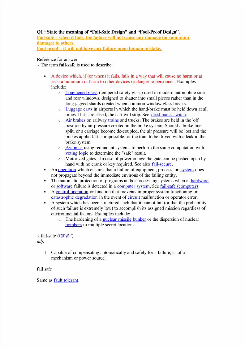
Q1 : State the meaning of “Fail-Safe Design” and “Fool-Proof Design”.Fail-safe – when it fails, the failure will not cause any damage (or minimum
damage) to others.
Fool-proof – it will not have any failure upon human mistake.
Reference for answer:~ The term fail-safe is used to describe:
• A device which, if (or when) it fails, fails in a way that will cause no harm or at
least a minimum of harm to other devices or danger to personnel. Examples
include:o Toughened glass (tempered safety glass) used in modern automobile side
and rear windows, designed to shatter into small pieces rather than in the
long jagged shards created when common window glass breaks.
o Luggage carts in airports in which the hand-brake must be held down at all
times. If it is released, the cart will stop. See dead man's switch.
o
Air brakes on railway trains and trucks. The brakes are held in the 'off'position by air pressure created in the brake system. Should a brake line
split, or a carriage become de-coupled, the air pressure will be lost and thebrakes applied. It is impossible for the train to be driven with a leak in the
brake system.
o Avionics using redundant systems to perform the same computation with
voting logic to determine the "safe" result.
o Motorized gates - In case of power outage the gate can be pushed open byhand with no crank or key required. See also fail-secure.
• An operation which ensures that a failure of equipment, process, or system does
not propagate beyond the immediate environs of the failing entity.
• The automatic protection of programs and/or processing systems when a hardware or software failure is detected in a computer system. See fail-safe (computer).
• A control operation or function that prevents improper system functioning or
catastrophic degradation in the event of circuit malfunction or operator error.
• A system which has been structured such that it cannot fail (or that the probability
of such failure is extremely low) to accomplish its assigned mission regardless of
environmental factors. Examples include:
o The hardening of a nuclear missile bunker or the dispersion of nuclear
bombers to multiple secret locations
~ fail-safe (f l'sf')
adj.
1. Capable of compensating automatically and safely for a failure, as of a
mechanism or power source.
fail safe
Same as fault tolerant.
8/14/2019 Instrument Engineer Test 1.pdf
http://slidepdf.com/reader/full/instrument-engineer-test-1pdf 2/22
fault tolerance (fölt täl··rns)
(systems engineering) The capability of a system to perform in accordance with designspecifications even when undesired changes in the internal structure or external
environment occur.
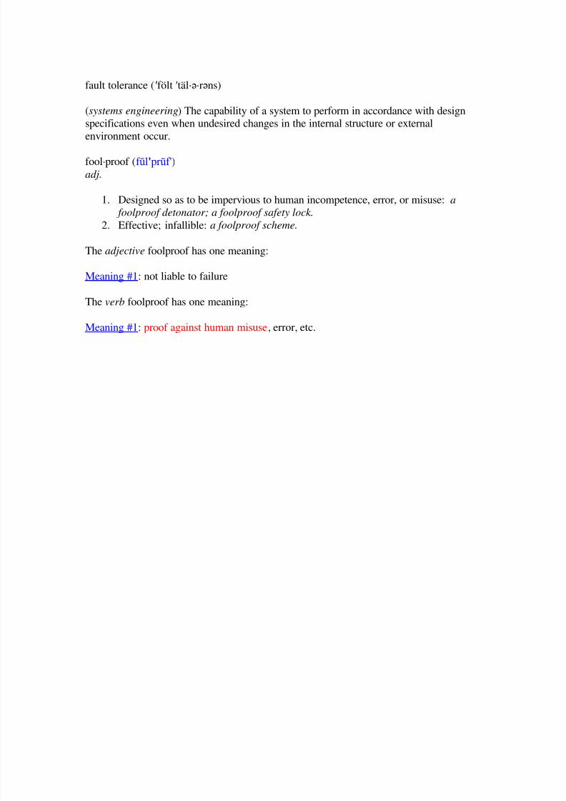
fool·proof (f l'prf')
adj.
1. Designed so as to be impervious to human incompetence, error, or misuse: a
foolproof detonator; a foolproof safety lock.
2. Effective; infallible: a foolproof scheme.
The adjective foolproof has one meaning:
Meaning #1: not liable to failure
The verb foolproof has one meaning:
Meaning #1: proof against human misuse, error, etc.
8/14/2019 Instrument Engineer Test 1.pdf
http://slidepdf.com/reader/full/instrument-engineer-test-1pdf 3/22
Q2 : State the meaning of “MTBF” and “MTTR”.MTBF – Mean time between failure
MTTR – Mean time to recovery
Reference for answer:
~ Mean-time-between-failure (MTBF) is the "average" time between failures, thereciprocal of the failure rate in the special case when failure rate is constant. Calculations
of MTBF assume that a system is "renewed", i.e. fixed, after each failure, and thenreturned to service immediately after failure. The average time between failure and being
returned to service is termed Mean Down Time (MDT).
A common misconception about the MTBF is that it specifies the time (on average) when
the likelihood of failure equals the likelihood of not having a failure. This is only true for
certain symmetric distributions. In many cases, such as the (non-symmetric) exponentialdistribution, this is not true. In particular, for an exponential failure distribution, the
probability that an item will fail by the MTBF is approximately 0.63. For typical
distributions with some variance, MTBF only represents a top-level statistic, thus is notsuitable for predicting detailed time of failure, as the uncertainty in actual failure
distribution manifests itself in variability in the time to failure distribution.
~ Mean time to recovery (MTTR) is the average time that a device will take to recover
from a non-terminal failure. Examples of such devices range from self-resetting fuses
(where the MTTR would be very short, probably seconds), up to whole systems whichhave to be replaced.
The MTTR would usually be part of a maintenance contract, where the user would paymore for a system whose MTTR was 24 hours, than for one of, say, 7 days. This does not
mean the supplier is guaranteeing to have the system up and running again within 24hours (or 7 days) of being notified of the failure. It does mean the average repair time willtend towards 24 hours (or 7 days). A more useful maintenance contract measure is the
maximum time to recovery which can be easily measured and the supplier held
accountable.
Note that some suppliers will interpret MTTR to mean 'mean time to respond', and others
will take it to mean 'mean time to replace/repair/recover/resolve'. The former indicates
that the supplier will acknowledge a problem and initiate mitigation within a certaintimeframe. Some systems may have a MTTR of zero, which means that they have
redundant components which can take over the instant the primary one fails, see RAID
for example. That said however, the failed device involved in this redundantconfiguration still needs to be returned to service and hence the device itself has a non-
zero MTTR even if the system as a whole (through redundancy) has a MTTR of zero.
8/14/2019 Instrument Engineer Test 1.pdf
http://slidepdf.com/reader/full/instrument-engineer-test-1pdf 4/22
Q3 : List more than 5 types of flow instruments.Thermal Mass
Coriolis Mass
RotameterPositive Displacement
Vortex sheddingMultiphaseTurbine
Reference for answer:
~ Flow measurement can be described by
Q = A · v, which means that the volume of fluid passing through a flowmeter is equal to
the cross-sectional area of the pipe (A) times the average velocity of the fluid (v); and
W = r · Q, which means that the mass flow of fluid passing through a flowmeter (A) isequal to the fluid density (r) times the volume of the fluid (Q).
Volumetric flowmeters directly measure the volume of fluid (Q) passing through the
flowmeter. The only flowmeter technology that measures volume directly is the positivedisplacement flowmeter.
Velocity flowmeters utilize techniques that measure the velocity (v) of the flowing stream
to determine the volumetric flow. Examples of flowmeter technologies that measurevelocity include magnetic, turbine, ultrasonic, and vortex shedding and fluidic
flowmeters.
Mass flowmeters utilize techniques that measure the mass flow (W) of the flowing
stream. Examples of flowmeter technologies that measure mass flow include Coriolis
mass and thermal flowmeters.
Inferential flowmeters do not measure volume, velocity or mass, but rather measure flow
by inferring its value from other measured parameters. Examples of flowmeter
technologies that measure inferentially include differential pressure, target and variablearea flowmeters.
Flow computers are often used to compensate flow measurements for actual processconditions, such as pressure, temperature, viscosity, and composition.
Additional flowmeter technologies include flowmeters that measure liquid flowing in anopen channel, and insertion flowmeters that measure flow at one location in a pipe and
use this measurement to infer the flow in the entire pipe. Insertion flow measurement
systems often use a flow computer to compensate for hydraulic effects.
8/14/2019 Instrument Engineer Test 1.pdf
http://slidepdf.com/reader/full/instrument-engineer-test-1pdf 5/22
Q4 : List 3 types of flow instruments that no straight run is required.Coriolis Mass Flowmeter
Rotameter
Positive Displacement FlowmetersDifferential Pressure Flowmeter (V-cone style only)
Reference for answer:
~ Coriolis Mass Flowmeter - This meter uses the Coriolis effect to measure the amountof mass moving through the element. The substance to be measured runs through a U-
shaped tube that is caused to vibrate in a perpendicular direction to the flow. Fluid forces
running through the tube interact with the vibration, causing it to twist. The greater theangle of the twist, the greater the flow
~ ROTAMETERs™ (Variable Area Meters) are named after ROTA, one of the European
inventors of this flow principle in the beginning of the century. ROTA invented therotating float, which is self-guiding and has less friction in the pipe so that a more precise
measurement is possible.
~ Positive Displacement Flowmeters
These meters are used for water applications when no straight pipe is available and
turbine meters and paddlewheel sensor would see too much turbulence. The positivedisplacement are also used for viscous liquids.
~ With its unique ability to self-condition flow, the V-Cone Flow Meter is a real space-
saver, eliminating the need for up/down stream straight pipe runs required by other DPtechnologies, such as orifice plates and venturi tubes.
8/14/2019 Instrument Engineer Test 1.pdf
http://slidepdf.com/reader/full/instrument-engineer-test-1pdf 6/22
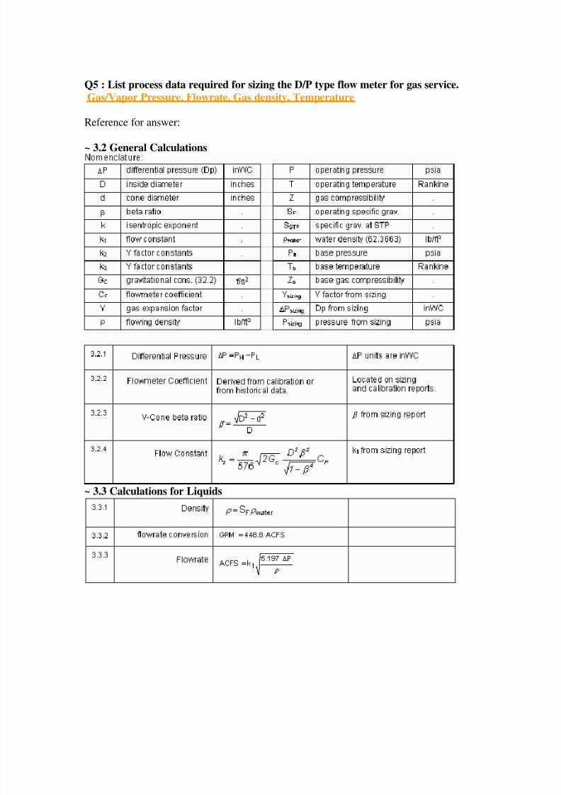
Q5 : List process data required for sizing the D/P type flow meter for gas service.
Gas/Vapor Pressure, Flowrate, Gas density, Temperature
Reference for answer:
~ 3.2 General Calculations
~ 3.3 Calculations for Liquids
8/14/2019 Instrument Engineer Test 1.pdf
http://slidepdf.com/reader/full/instrument-engineer-test-1pdf 7/22
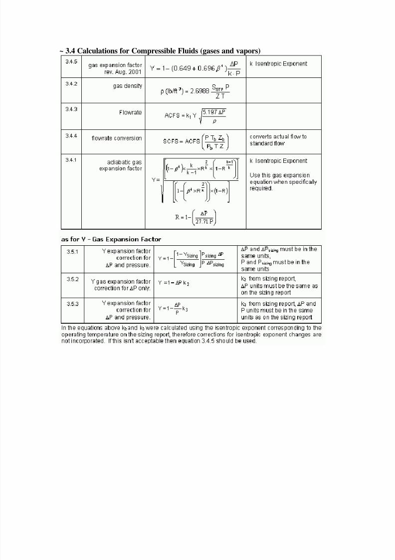
~ 3.4 Calculations for Compressible Fluids (gases and vapors)
8/14/2019 Instrument Engineer Test 1.pdf
http://slidepdf.com/reader/full/instrument-engineer-test-1pdf 8/22
Q6 : Choose correct instrument type that are able to measure the interface liquidlevel
Radar Type (yes), D/p Type (yes), Float Type (yes), Ultrasonic Type (yes), Displacer
Type (yes)
Reference for answer:
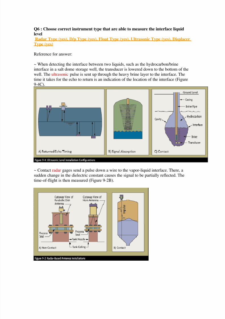
~ When detecting the interface between two liquids, such as the hydrocarbon/brineinterface in a salt dome storage well, the transducer is lowered down to the bottom of the
well. The ultrasonic pulse is sent up through the heavy brine layer to the interface. The
time it takes for the echo to return is an indication of the location of the interface (Figure9-4C).
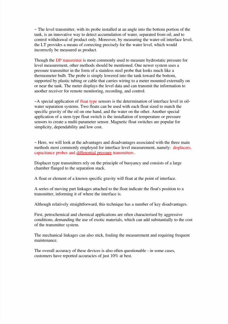
~ Contact radar gages send a pulse down a wire to the vapor-liquid interface. There, a
sudden change in the dielectric constant causes the signal to be partially reflected. The
time-of-flight is then measured (Figure 9-2B).
8/14/2019 Instrument Engineer Test 1.pdf
http://slidepdf.com/reader/full/instrument-engineer-test-1pdf 9/22
8/14/2019 Instrument Engineer Test 1.pdf
http://slidepdf.com/reader/full/instrument-engineer-test-1pdf 10/22
Capacitance probes comprise a long metallic probe, which normally enters the top of the
separator vessel and extends to its lowest point.
Liquid level and interface are detected by measuring the capacitance value between thewall of the vessel holding the liquid and the probe itself.
Again, the aggressive nature of most chemical and petrochemical applications willrequire the use of exotic materials, adding to the cost of the installation.
Another complication associated with this technology is the measurement of stickysubstances, which can coat the metal, resulting in measurement uncertainties and poor
readings.
Other factors such as foam on the liquid surface or vibration of the tank can also conspire
to reduce measurement certainty or even render the probe inoperable.
Remote seal differential pressure transmitters probably offer the best solution for themeasurement of liquid interface levels.
With this technique, when the distance between the taps on the separation stack is filled
only with the lighter liquid, the differential pressure is minimum value or the lowestrange value (LRV) of the transmitter.
When it is filled with the heavier liquid, the differential pressure is at its maximum value,
or the upper range value (URV) of the transmitter.
Although this technique overcomes many of the problems associated with the previously
described methods, particularly with respect to corrosion, it does have one maindrawback.
The small difference in both the specific gravity of the two liquids and the distance
between the taps on the separation stack results in a very small differential pressure span.
In many cases, the size of this span is often lower than the recommended minimum span
for most remote seal transmitters.
One way of overcoming this problem is to use remote seals and transmitters which are
sensitive enough to detect very low span changes.
8/14/2019 Instrument Engineer Test 1.pdf
http://slidepdf.com/reader/full/instrument-engineer-test-1pdf 11/22
Q7 : Pressure Gauge installed in steam service shall have aWater column
Reference for answer:
~ Article 66. Pressure GaugesA pressure gauge shall be attached to the steam space or water column or to a steam-side
connection leading to such water column of any steam boiler in accordance with thefollowings:
(1) The direct influx of steam into the pressure gauge shall be precluded.
(2) Any valve or cock shall be so designed as to clearly show whether it is open orclosed.
(3) The steam connection for the pressure gauge shall have such construction that is not
easily clogged.
(4) The highest degree of the scale on any pressure gauge shall be in a range not lowerthan 1.5 times but not higher than 3 times the maximum allowable working pressure of
the boiler(5) The diameter of the face of a pressure gauge shall be such that ensures easy reading.
8/14/2019 Instrument Engineer Test 1.pdf
http://slidepdf.com/reader/full/instrument-engineer-test-1pdf 12/22
Q8 : Impulse piping in liquid service for pressure and flow instruments shall beoriented and sloped (downward) so that it remain full of liquid.
Reference for answer:
~ Application Cautions for Differential Pressure Flowmeters Because of the nonlinearrelationship between flow and differential pressure, the accuracy of flow measurement in
the lower portion of the flow range can be degraded. Plugging of the impulse piping canbe a concern for many services. For slurry service, purges should be used to keep the
impulse piping from plugging. For liquid service, impulse piping should be oriented and
sloped so that it remains full of liquid and does not collect gas. For gas service, impulsepiping should be oriented and sloped so that it remains full of gas and does not collect
liquids. In vapor service, vapor may be allowed to condense in some of the impulse
piping to form a liquid seal between the hot vapor and transmitter in order to protect the
transmitter from heat.
~ The following restrictions and recommendations apply to impulse piping location:1. Impulse piping that runs horizontally must slope at least one inch per foot (83 mm/m).• Slope downward (toward the electronics) for liquid and steam applications• Slope upward (toward the electronics) for gas applications.2. For applications with temperature below 250 °F (121 °C), impulse piping should be asshort as possible to minimize temperature changes. Insulation may be required.3. For applications above 250 °F (121 °C), impulse piping should have a minimum length ofone foot (0.3048 m) for every 100 °F (38°C) temperature increase over 250 °F (121 °C).Impulse piping must be non-insulated to reduce fluid temperature. Any threadedconnections should be checked after the system reaches the intended temperaturebecause connections may come loose with contraction and expansion caused bytemperature change.4. Outdoor installations for liquid, saturated gas, or steam may require insulation and heattracing to prevent freezing.
5. When impulse piping is longer than six feet (1.8 m) the high and low impulse lines mustbe positioned together to maintain equal temperature. They must be supported toprevent sagging and vibration.6. Impulse lines should be positioned in protected areas or against walls or ceilings. Useappropriate pipe sealing compound rated for the service temperature on all threadedconnections. Do not place the impulse piping near high temperature piping or equipment.
8/14/2019 Instrument Engineer Test 1.pdf
http://slidepdf.com/reader/full/instrument-engineer-test-1pdf 13/22
Q9 : Impulse piping in gas service for pressure and flow instruments shall beoriented and sloped (upward) so that it remain full of gas.
Reference for answer:
~ Application Cautions for Differential Pressure Flowmeters Because of the nonlinearrelationship between flow and differential pressure, the accuracy of flow measurement in
the lower portion of the flow range can be degraded. Plugging of the impulse piping canbe a concern for many services. For slurry service, purges should be used to keep the
impulse piping from plugging. For liquid service, impulse piping should be oriented and
sloped so that it remains full of liquid and does not collect gas. For gas service, impulsepiping should be oriented and sloped so that it remains full of gas and does not collect
liquids. In vapor service, vapor may be allowed to condense in some of the impulse
piping to form a liquid seal between the hot vapor and transmitter in order to protect the
transmitter from heat.
~ The following restrictions and recommendations apply to impulse piping location:1. Impulse piping that runs horizontally must slope at least one inch per foot (83 mm/m).• Slope downward (toward the electronics) for liquid and steam applications• Slope upward (toward the electronics) for gas applications.2. For applications with temperature below 250 °F (121 °C), impulse piping should be asshort as possible to minimize temperature changes. Insulation may be required.3. For applications above 250 °F (121 °C), impulse piping should have a minimum length ofone foot (0.3048 m) for every 100 °F (38°C) temperature increase over 250 °F (121 °C).Impulse piping must be non-insulated to reduce fluid temperature. Any threadedconnections should be checked after the system reaches the intended temperaturebecause connections may come loose with contraction and expansion caused bytemperature change.4. Outdoor installations for liquid, saturated gas, or steam may require insulation and heattracing to prevent freezing.
5. When impulse piping is longer than six feet (1.8 m) the high and low impulse lines mustbe positioned together to maintain equal temperature. They must be supported toprevent sagging and vibration.6. Impulse lines should be positioned in protected areas or against walls or ceilings. Useappropriate pipe sealing compound rated for the service temperature on all threadedconnections. Do not place the impulse piping near high temperature piping or equipment.
8/14/2019 Instrument Engineer Test 1.pdf
http://slidepdf.com/reader/full/instrument-engineer-test-1pdf 14/22
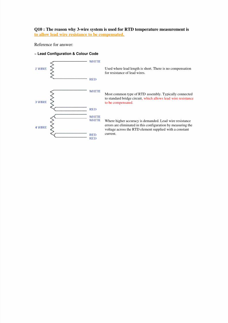
Q10 : The reason why 3-wire system is used for RTD temperature measurement isto allow lead wire resistance to be compensated.
Reference for answer:
~ Lead Configuration & Colour Code
Used where lead length is short. There is no compensation
for resistance of lead wires.
Most common type of RTD assembly. Typically connected
to standard bridge circuit, which allows lead wire resistance
to be compensated.
Where higher accuracy is demanded. Lead wire resistance
errors are eliminated in this configuration by measuring the
voltage across the RTD element supplied with a constant
current.
8/14/2019 Instrument Engineer Test 1.pdf
http://slidepdf.com/reader/full/instrument-engineer-test-1pdf 15/22
Q11 : Cable between thermocouple element and temperature transmitter is copper
Reference for answer:
~ 2.1 Terminating the Thermocouple
A practical industrial or laboratory thermocouple consists of only a single (measuring) junction;the reference is always the terminal temperature. If the terminal temperature is other thancontrolled and stable, procedures are necessary to deal with the situation. Possible measures are:-
a) Measure the terminal temperature accurately and compensate accordingly in calculating themeasured value.
b) Locate the terminals in a thermally controlled enclosure
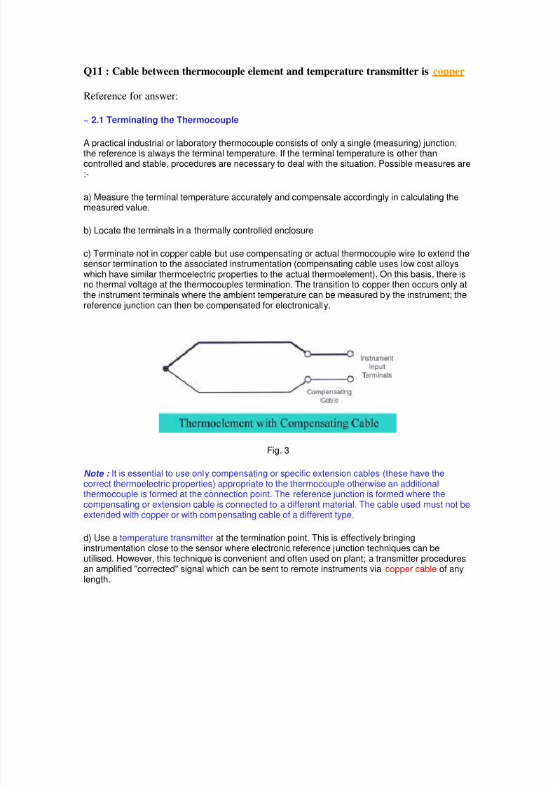
c) Terminate not in copper cable but use compensating or actual thermocouple wire to extend thesensor termination to the associated instrumentation (compensating cable uses low cost alloys
which have similar thermoelectric properties to the actual thermoelement). On this basis, there isno thermal voltage at the thermocouples termination. The transition to copper then occurs only atthe instrument terminals where the ambient temperature can be measured by the instrument; thereference junction can then be compensated for electronically.
Fig. 3
Note : It is essential to use only compensating or specific extension cables (these have thecorrect thermoelectric properties) appropriate to the thermocouple otherwise an additionalthermocouple is formed at the connection point. The reference junction is formed where thecompensating or extension cable is connected to a different material. The cable used must not beextended with copper or with compensating cable of a different type.
d) Use a temperature transmitter at the termination point. This is effectively bringing
instrumentation close to the sensor where electronic reference junction techniques can beutilised. However, this technique is convenient and often used on plant; a transmitter proceduresan amplified "corrected" signal which can be sent to remote instruments via copper cable of anylength.
8/14/2019 Instrument Engineer Test 1.pdf
http://slidepdf.com/reader/full/instrument-engineer-test-1pdf 16/22
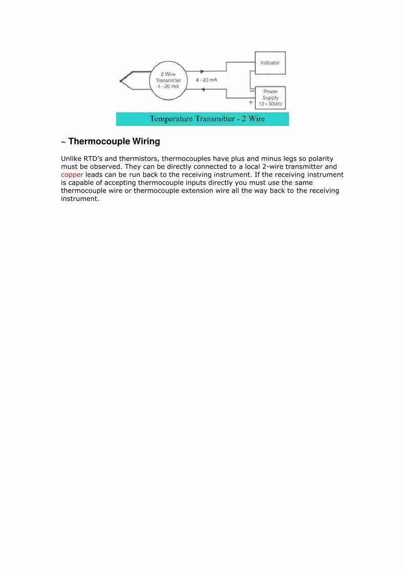
~ Thermocouple Wiring
!
! "
8/14/2019 Instrument Engineer Test 1.pdf
http://slidepdf.com/reader/full/instrument-engineer-test-1pdf 17/22
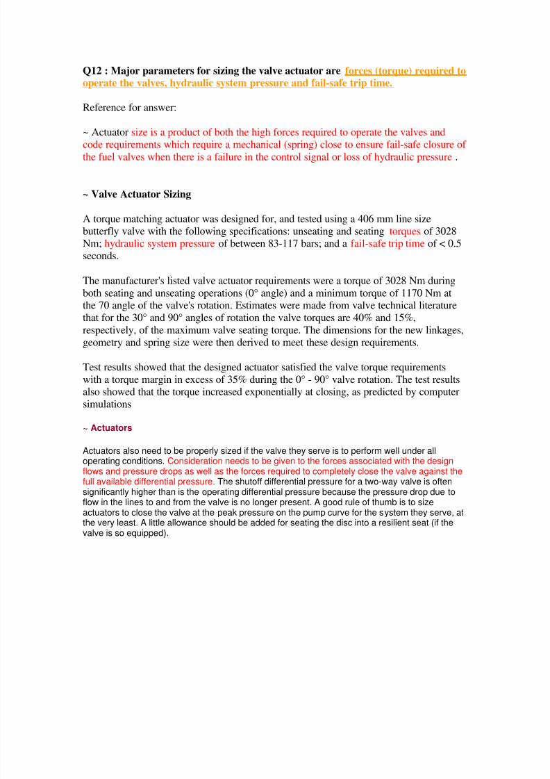
Q12 : Major parameters for sizing the valve actuator are forces (torque) required tooperate the valves, hydraulic system pressure and fail-safe trip time.
Reference for answer:
~ Actuator size is a product of both the high forces required to operate the valves andcode requirements which require a mechanical (spring) close to ensure fail-safe closure of
the fuel valves when there is a failure in the control signal or loss of hydraulic pressure .
~ Valve Actuator Sizing
A torque matching actuator was designed for, and tested using a 406 mm line size
butterfly valve with the following specifications: unseating and seating torques of 3028Nm; hydraulic system pressure of between 83-117 bars; and a fail-safe trip time of < 0.5
seconds.
The manufacturer's listed valve actuator requirements were a torque of 3028 Nm during
both seating and unseating operations (0° angle) and a minimum torque of 1170 Nm atthe 70 angle of the valve's rotation. Estimates were made from valve technical literature
that for the 30° and 90° angles of rotation the valve torques are 40% and 15%,
respectively, of the maximum valve seating torque. The dimensions for the new linkages,
geometry and spring size were then derived to meet these design requirements.
Test results showed that the designed actuator satisfied the valve torque requirements
with a torque margin in excess of 35% during the 0° - 90° valve rotation. The test resultsalso showed that the torque increased exponentially at closing, as predicted by computer
simulations
~ Actuators
Actuators also need to be properly sized if the valve they serve is to perform well under alloperating conditions. Consideration needs to be given to the forces associated with the designflows and pressure drops as well as the forces required to completely close the valve against thefull available differential pressure. The shutoff differential pressure for a two-way valve is oftensignificantly higher than is the operating differential pressure because the pressure drop due toflow in the lines to and from the valve is no longer present. A good rule of thumb is to sizeactuators to close the valve at the peak pressure on the pump curve for the system they serve, atthe very least. A little allowance should be added for seating the disc into a resilient seat (if thevalve is so equipped).
8/14/2019 Instrument Engineer Test 1.pdf
http://slidepdf.com/reader/full/instrument-engineer-test-1pdf 18/22
Q13 : Control valve characteristics installed in the condition, where most of thesystem pressure drop is not across the valve is INSTALLED CHARACTERISTIC.
Reference for answer:
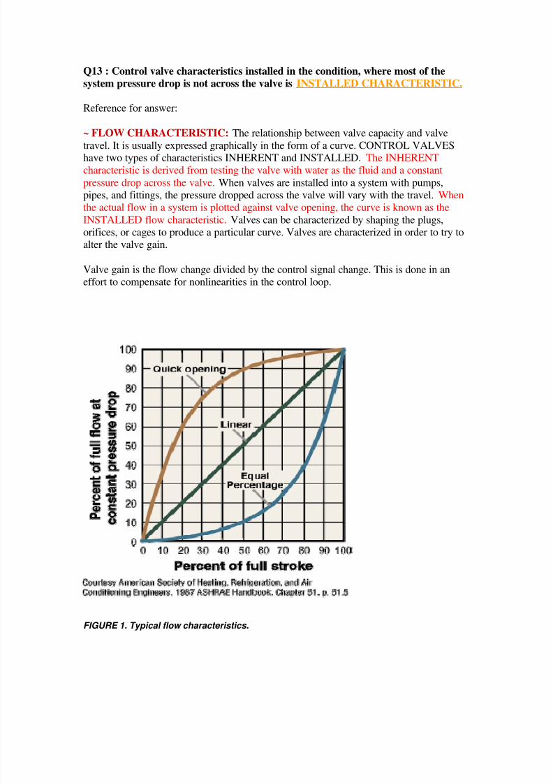
~ FLOW CHARACTERISTIC: The relationship between valve capacity and valvetravel. It is usually expressed graphically in the form of a curve. CONTROL VALVEShave two types of characteristics INHERENT and INSTALLED. The INHERENT
characteristic is derived from testing the valve with water as the fluid and a constant
pressure drop across the valve. When valves are installed into a system with pumps,
pipes, and fittings, the pressure dropped across the valve will vary with the travel. Whenthe actual flow in a system is plotted against valve opening, the curve is known as the
INSTALLED flow characteristic. Valves can be characterized by shaping the plugs,
orifices, or cages to produce a particular curve. Valves are characterized in order to try toalter the valve gain.
Valve gain is the flow change divided by the control signal change. This is done in aneffort to compensate for nonlinearities in the control loop.
FIGURE 1. Typical flow characteristics.
8/14/2019 Instrument Engineer Test 1.pdf
http://slidepdf.com/reader/full/instrument-engineer-test-1pdf 19/22
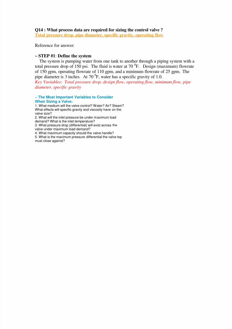
Q14 : What process data are required for sizing the control valve ?Total pressure drop, pipe diameter, specific gravity, operating flow
Reference for answer:
~ STEP #1: Define the systemThe system is pumping water from one tank to another through a piping system with atotal pressure drop of 150 psi. The fluid is water at 70 0F. Design (maximum) flowrate
of 150 gpm, operating flowrate of 110 gpm, and a minimum flowrate of 25 gpm. The
pipe diameter is 3 inches. At 700F, water has a specific gravity of 1.0.
Key Variables: Total pressure drop, design flow, operating flow, minimum flow, pipe
diameter, specific gravity
~ The Most Important Variables to ConsiderWhen Sizing a Valve:1. What medium will the valve control? Water? Air? Steam?What effects will specific gravity and viscosity have on the
valve size?2. What will the inlet pressure be under maximum loaddemand? What is the inlet temperature?3. What pressure drop (differential) will exist across thevalve under maximum load demand?4. What maximum capacity should the valve handle?5. What is the maximum pressure differential the valve topmust close against?
8/14/2019 Instrument Engineer Test 1.pdf
http://slidepdf.com/reader/full/instrument-engineer-test-1pdf 20/22
Q15 : Balance bellows type safety valve are used, where the variation in backpressure exceeding 10% of set pressure.
Reference for answer:
~ When must I specify the use of a Balanced Bellows pressure relief valve?
Balanced bellows as used in our 2600 Series BalanSeal design are generallyspecified for a variety of reasons. The most prominent is to nullify the effects ofback pressure in the discharge system on the valves set pressure. They are alsoused to protect the principal guiding surfaces, spring, and valve top works fromcoming in contact with a corrosive fluid. This may allow for the use of lessexpensive metallurgy as the bellows isolates the trim from the fluid. A balancedbellows valve should always be used when the variation in back pressureexceeds 10 % of set pressure.
~ Balanced safety relief valve - A balanced valve incorporates a means of minimisingthe effect of backpressure on the operational characteristics of the valve.
~ Bellows safety valve - A direct loaded safety valve wherein sliding and (partially orfully) rotating elements and springs are protected against the effects of the fluids by a
bellows. The bellows may be of such a design that it compensates for influences of
backpressure.
8/14/2019 Instrument Engineer Test 1.pdf
http://slidepdf.com/reader/full/instrument-engineer-test-1pdf 21/22
Q16 : In the safety valve design based on the ASME Section VIII, over pressure is10% or 3psi whichever is greater.
Reference for answer:
~ ASME VIII valve - A safety relief valve conforming to the requirements of Section
VIII of the ASME pressure vessel code for pressure vessel applications which will openwithin 10% overpressure and close within 7%. Identified by a National Board ‘UV’
stamp.
~ paragraph UG-125 of ASME Section VIII, Division 1. It states in part,
"All pressure vessels other than unfired steam boilers shall be protected by a pressure
relief device that shall prevent the pressure from rising more than 10% or 3 psi,whichever is greater, above the maximum allowable working pressure except as
permitted in (1) and (2) below."
Sub-paragraphs (1) and (2) mention cases where the pressure rise may be higher.
~ ASME Section VIII, Division 1 clearly states in Paragraph UG-131 (c)(1) that
"Capacity certification tests shall be conducted at a pressure which does not exceed thepressure for which the pressure relief valve is set to operate by more than 10% or 3 psi,
whichever is greater, except as provided in (c)(2)..."
Sub-paragraph (c)(2) covers a fire case.

8/14/2019 Instrument Engineer Test 1.pdf
http://slidepdf.com/reader/full/instrument-engineer-test-1pdf 22/22
Q17 : Last major construction drawings for instrumentation to be prepared.
Piping and Instrumentation Drawings (PNID)
Loop Drawings