Embed Size (px)
Citation preview
IAC-06-D2.5.09
1
INTEGRATED THERMAL PROTECTION SYSTEMS AND HEAT RESISTANT STRUCTURES T. Pichon, M. Lacoste, and R. Barreteau
Snecma Propulsion Solide, SAFRAN Group, Le Haillan, France D. E. Glass
NASA Langley Research Center, Hampton, VA, USA
Abstract
The Integrated Thermal Protection Systems and Heat Resistant Structure was a project funded within the Exploration Systems Research and Technology (ESR&T) section of the Space Exploration Initiative (SEI). It was performed by a team composed of Snecma Propulsion Solide, NASA, MT Aerospace, and Materials Research & Design (MR&D). The objective of this project was to validate innovative thermal protection systems (TPS) that could be applied to future space vehicles, both manned and unmanned, for high-energy atmospheric maneuver phases. Such phases comprise not only the direct re-entries into a planetary atmosphere, but also aero-capture and aero-braking trajectories for energy efficient orbital parameters modification. The project included three distinct branches, each one aiming at validating one technology variant of the TPS. The availability of several technology variants with complementary capabilities allows tailoring the design to any foreseeable kind of vehicle and mission profile. All three variants are based on the use of thermo-structural composite materials that were developed for extreme environments applications. The first and main branch of the project was dedicated to the “CAS” (Ceramic Aft Shield) technology. This TPS is composed of ceramic matrix composite (CMC) elements, filled with an internal insulation and mounted on a cold structure. It is particularly well suited to applications with a moderate re-entry heat-flux, needing a high degree of reusability. The CAS system design was entrusted to MT Aerospace, as well as the design and manufacturing of the leading edges and of the cold structure, while Snecma Propulsion Solide was responsible for the design and manufacturing of panels and internal
insulation. The validation of this technology through this program was planned through a series of testing activities, from small-scale elementary material tests to a large demonstrator made of several assembled TPS elements and tested with representative thermo-mechanical loads. The second branch of activity was dedicated to the Sepcore® technology. This TPS makes use of a thin ablative layer that is mounted on top of the CMC panels, and which withstands much higher heat fluxes, for very demanding re-entries such as direct returns from the Moon or from Mars. This leads to calculated mass savings of approximately 30% compared to the simple ablative technology on a cold structure. Snecma Propulsion Solide was entrusted with the complete design and manufacturing of a demonstrator required to validate this technology. Sepcore® was to be tested in a large plasma test facility to assess the combined ablative material and CMC performance in a fully representative environment. NASA Ames Research center (ARC) also contributed by providing support for the ablative material selection and sizing. Another large scale demonstrator was also to be tested in combined thermal and mechanical loads at NASA Dryden Flight Research Center (DFRC). The third branch was focused on the design of a deployable decelerator concept. This consists of deployable CMC panels that increase the vehicle ballistic coefficient, enabling an extended range of maneuvers and reducing the areal heat loads. The design of this technology was entirely entrusted to MR&D, which relied on NASA Langley Research Center (LaRC) for the deployment mechanisms design. Snecma Propulsion Solide was responsible for the manufacturing of the CMC test articles, as a demonstrator made of one deployable panel was foreseen to validate this technology. Finally HMS concepts were investigated by DFRC in support of testing activities.
IAC-06-D2.5.09
2
Unfortunately, due to a major restructuring of the Space Exploration Initiative, the project was cancelled before it was led to its term. Nevertheless, significant work was performed on the trajectory analysis as well as on the conceptual design of each of the three technology variants. Mission Definition, Trajectory Development and
Aeroheating Environment Definition
The missions selected for this study were used to develop the trajectory, and ultimately the entry thermal environments the proposed concepts must withstand. The range of missions is described along with the rationale for a prioritization and selection of the missions for consideration. Missions considered at the outset of the project included manned and robotic missions, to and from: low Earth orbit (LEO), Geosynchronous orbit (GEO), the moon, and Mars, as well as extended planetary missions. The missions considered are (not prioritized):
• Earth return from LEO, MEO, GEO, moon, Mars
• Aeroentry for both Earth and Mars • Aerocapture and aerobraking for both Earth
and Mars • Manned and robotic missions
The key contributors to the atmospheric entry environments and heating levels the vehicle TPS and material must withstand are 1) the entry state – velocity and flight-path angle (this will be determined outside of this study as a function of the required mission scenario, including the departure conditions and the time allowed for return to Earth), and 2) the ballistic coefficient which is a function of the vehicle geometry and mass (also determined outside of this study).
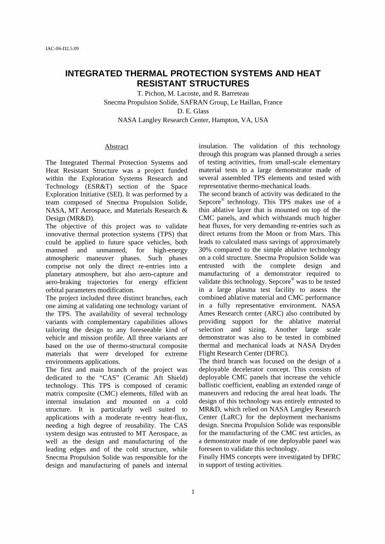
Lunar Direct Return (LDR): The flight-path angle (-5.8 deg) and velocity (11,075 m/s or 36,334 ft/s) for the nominal direct lunar return were determined based upon Apollo lunar mission data. Initial conditions for the nominal (Case 0) and off-nominal lunar direct cases are listed in Table 1. The range of initial velocities was selected based upon experience and previous work (examination of actual Apollo entry trajectories and recent lunar abort analyses). Ballistic coefficients were selected to cover a range of potential entry concepts, including capsules and aerodynamic decelerator
concepts. Ballistic coefficients were achieved by altering the vehicle mass, keeping the reference area (and therefore aerodynamics) the same. Minimum and maximum allowable flight-path angles were then determined for each combination of velocity and ballistic coefficient. POST2 was allowed to optimize the initial flight-path angle (minimum or maximum) under the constraints of a maximum total acceleration of 10 g’s and a maximum skip-out altitude of 121,920 m (400,000 ft). POST2 code was allowed to modulate bank angle to help optimize each case. Plots of altitude vs. Earth relative velocity are shown in Figure 1. Table 1. Initial conditions for lunar direct trade matrix.
LDR - Trade Matrix (Metric)
Case # Initial
velocity (m/s)
Initial flight path angle
(deg)
Ballistic coefficient (~Mach 30)
(kg/m2) 0 11075 -5.80 356 1 9765 -3.99 122 2 9765 -5.21 488 3 9765 -6.65 122 4 9765 -7.11 488 5 12201 -5.09 122 6 12201 -5.61 488 7 12201 -6.63 122 8 12201 -7.40 488 9 11075 -4.63 122 10 11074 -6.73 122 11 11075 -5.13 488 12 11075 -7.29 488
Figure 1. Geodetic altitude versus Earth relative
velocity for direct Earth entry from Luna.
Two additional LDR entries were generated specifically for the decelerator concepts. These
IAC-06-D2.5.09
3
trajectories, designated LDR-13 and LDR-14, more accurately match the MR&D decelerator concept in terms of weight and size as reflected in the ballistic coefficients. The mid-velocity entry state was assumed, 11,075 m/s (36,334 ft/s) inertial velocity and flight path angle ~ -4.55 deg, for both cases. The ballistic coefficients, 95 kg/m2 for LDR-13 and 100 kg/m2 for LDR-14 are slightly lower than those included in the initial parametric range for which the full LDR trajectory set is shown in Figure 1. The 95 kg/m2 ballistic coefficient is based on a decelerator concept that is 4 m in radius and derived from the baseline Apollo CM (3.91 m diameter). The 100 kg/m2 decelerator concept is 5.4 m in total radius and is derived from the CEV concept as currently proposed, 5.5 m diameter.
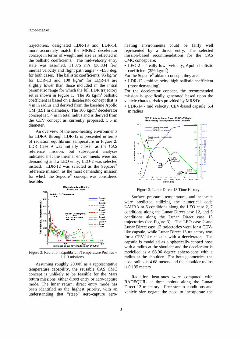
An overview of the aero-heating environments for LDR-0 through LDR-12 is presented in terms of radiation equilibrium temperature in Figure 2. LDR Case 9 was initially chosen as the CAS reference mission, but subsequent analyses indicated that the thermal environments were too demanding and a LEO entry, LEO-2 was selected instead. LDR-12 was selected as the Sepcore® reference mission, as the most demanding mission for which the Sepcore® concept was considered feasible.
Figure 2. Radiation Equilibrium Temperature Profiles –
LDR missions.
Assuming roughly 2000K as a representative temperature capability, the reusable CAS CMC concept is unlikely to be feasible for the Mars return missions, either direct entry or aero-capture mode. The lunar return, direct entry mode has been identified as the highest priority, with an understanding that “steep” aero-capture aero-
heating environments could be fairly well represented by a direct entry. The selected mission-based recommendations for the CAS CMC concept are: • LEO-2 – “really low” velocity, Apollo ballistic
coefficient (356 kg/m2) For the Sepcore® ablator concept, they are: • LDR-12 - mid velocity, high ballistic coefficient
(most demanding) For the decelerator concept, the recommended mission is specifically generated based upon the vehicle characteristics provided by MR&D: • LDR-14 - mid velocity, CEV-based capsule, 5.4
m radius
Time, sec
Tota
lHea
tRat
e,w
/cm
2
Altit
ude,
km
Tota
lHea
tLoa
d,Jo
ules
/m2
0 100 200 300 400 500 600 700 800 900
0
20
40
60
80
100
0
20
40
60
80
100
120
140
0
2E+07
4E+07
6E+07
8E+07
1E+08
1.2E+08
1.4E+08
1.6E+08
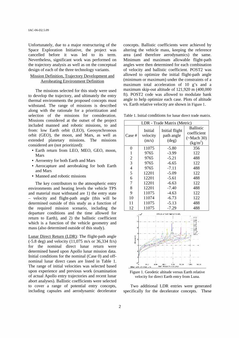
Total Heat Rate, w/cm2Altitude, kmTotal Heat Load, Joules/m2
CFD Points for Lunar Direct 13 BC=95 kg/m2
Time History for Stagnation Point Location
Peak Convective Heating t=106st=106sM=37.1
t=340sM=29.1
t=470sM=19.3Peak Dyn P
t=670sM=6.7
t=725sM=3.4
Figure 3. Lunar Direct 13 Time History.
Surface pressure, temperature, and heat-rate were predicted utilizing the numerical code LAURA at 6 conditions along the LEO case 2, 7 conditions along the Lunar Direct case 12, and 5 conditions along the Lunar Direct case 13 trajectories (see Figure 3). The LEO case 2 and Lunar Direct case 12 trajectories were for a CEV-like capsule, while Lunar Direct 13 trajectory was for a CEV-like capsule with a decelerator. The capsule is modelled as a spherically-capped nose with a radius at the shoulder and the decelerator is modelled as a 66.96 degree sphere-cone with a radius at the shoulder. For both geometries, the nose radius is 4.68 meters and the shoulder radius is 0.195 meters.
Radiation heat-rates were computed with
RADEQUIL at three points along the Lunar Direct 12 trajectory. Free stream conditions and vehicle size negate the need to incorporate the
IAC-06-D2.5.09
4
effects of radiation in the LEO 2 data; hence, only convective values were required. For the Lunar Direct 13 trajectory, a non-negligible fraction of the heat-rate and heat-load will be due to radiation. Additional details of the mission, trajectory, and loads can be found in Ref. 1.
CAS
The Ceramic Aft Shield (CAS) design is based on a blunt aft body representative of an Apollo shaped re-entry vehicle, as shown in Figure 4, and is sized to withstand the reference heat-flux shown in Figure 5 (700 kW.m-2 max.).
Figure 4. CAS overall geometry
0
100 000
200 000
300 000
400 000
500 000
600 000
700 000
800 000
0 100 200 300 400 500 600 700 800 900 1 000 1 100
Time (s)
Full
cata
lytic
hea
t rat
e (W
/m²)
Stg pointCorner
Figure 5. Reference heat flux for CAS (LEO2)
It is mainly composed of an annular array of leading-edge elements, a circular array of panels, and a central panel. For the leading edge design, MT Aerospace compared several previously developed TPS elements. Two of them were selected for preliminary thermal and mechanical analyses in order to assess their performance in the specified
re-entry conditions as shown in Figure 6 and Figure 7.
Figure 6. Concept #1
Figure 7. Concept #2
The analyses showed that concept #1 could be sized to withstand the specified mechanical and thermal loads without much difficulty. It was then selected as a back-up solution, and the activity was then only focused on concept #2 that was believed to offer advantages in terms of simplicity and cost. Three variants of concept #2 were studied and preliminary CAD models of the three configurations have been built, as shown in Figure 8 : • the reference configuration has two stiffeners
and metallic stand-offs, • the second configuration has two stiffeners,
and CMC stand-offs, • the third configuration has no stiffeners and
CMC stand-offs.
Figure 8. Reference configuration (left), first variant (middle) and second variant (right)
For the panels, Snecma Propulsion Solide performed a trade-off among the CMC panel concepts already studied, in order to select the
IAC-06-D2.5.09
5
best-suited basis for the CAS application. It appeared that concept #3 offered the best compromise in terms of technical performance and manufacturing ability. This concept is an improvement of concept #1: it is a CMC panel with four integrated stiffeners and metallic stand-offs. Several preliminary thermo-mechanical analyses have been performed on two panel sizes: 400×400 mm and 800×400 mm. The objective was to determine whether such panels would comply with the specified re-entry requirements, both in terms of aerodynamic profile deformation and in terms of stress level in the CMC panel. It turns out that small panels can be sized with regards to these criteria relatively easily. For large panels, it is more difficult as a profile deformation of 3.5 mm is observed, for a maximum specification of 3 mm as shown in Figure 9.
Figure 9. Thermo-mechanical analysis of a large panel
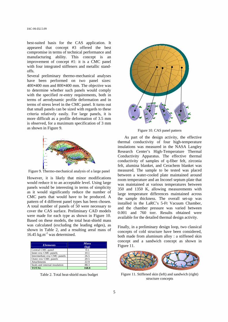
However, it is likely that minor modifications would reduce it to an acceptable level. Using large panels would be interesting in terms of simplicity as it would significantly reduce the number of CMC parts that would have to be produced. A pattern of 4 different panel types has been chosen. A total number of panels of 50 were necessary to cover the CAS surface. Preliminary CAD models were made for each type as shown in Figure 10. Based on these models, the total heat-shield mass was calculated (excluding the leading edges), as shown in Table 2, and a resulting areal mass of 16.45 kg.m-2 was determined.
Elements Mass (kg)
Central CMC panel 0.5 Inner row CMC panels 10.1 Intermediate row CMC panels 26.5 Outer row CMC panels 20.5 Attachments 22.9 Seals and internal insulation 88.3 TOTAL 168.8
Table 2. Total heat-shield mass budget
Figure 10. CAS panel pattern
As part of the design activity, the effective thermal conductivity of four high-temperature insulations was measured in the NASA Langley Research Center’s High-Temperature Thermal Conductivity Apparatus. The effective thermal conductivity of samples of q-fiber felt, zirconia felt, alumina blanket, and Cerachem blanket was measured. The sample to be tested was placed between a water-cooled plate maintained around room temperature and an Inconel septum plate that was maintained at various temperatures between 350 and 1350 K, allowing measurements with large temperature differences maintained across the sample thickness. The overall set-up was installed in the LaRC’s 5-Ft Vacuum Chamber, and the chamber pressure was varied between 0.001 and 760 torr. Results obtained were available for the detailed thermal design activity.
Finally, in a preliminary design loop, two classical concepts of cold structure have been considered, both made from aluminum alloy : a stiffened skin concept and a sandwich concept as shown in Figure 11.
Figure 11. Stiffened skin (left) and sandwich (right)
structure concepts
IAC-06-D2.5.09
6
Sepcore® The principle of the Sepcore® technology is to minimize the thickness of ablative material required on a TPS element by attaching it to a CMC supporting element. The ablative layer is then sized so that the temperature at the interface remains compatible with the CMC material, which leads to a significantly reduced ablator thickness. A lightweight internal insulation is then necessary, as for the CAS, to insulate the cold part of the shield or of the vehicle from the hot CMC elements, as shown in Figure 12.
Figure 12. Sepcore® TPS concept
The result is an overall mass saving that can reach more than 30% compared to a classical ablative heatshield technology, depending on mission requirements. The heat loads used for sizing correspond to a direct reentry trajectory from the Moon. From the twelve trajectories of this type analyzed by NASA LaRC, LDR12 was selected as it corresponds to one of the most severe cases, while remaining similar to past experience on the Sepcore® technology. The corresponding heat flux is presented in Figure 13 (11.4 MW.m-2 max.)..
0
2 000 000
4 000 000
6 000 000
8 000 000
10 000 000
12 000 000
0 100 200 300 400 500 600 700 800 900Time (s)
Full
cata
lytic
hea
t rat
e (W
/m²)
Stg pointCorner
Figure 13. Reference heat flux for Sepcore® (LDR12)
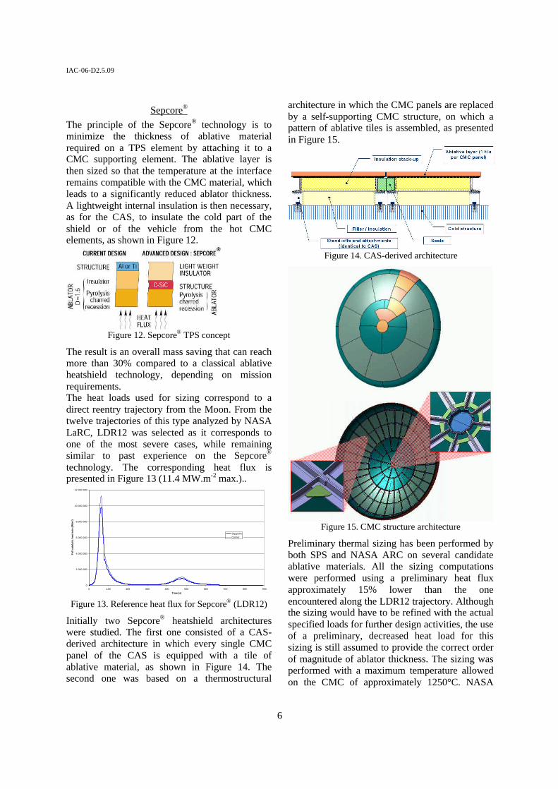
Initially two Sepcore® heatshield architectures were studied. The first one consisted of a CAS-derived architecture in which every single CMC panel of the CAS is equipped with a tile of ablative material, as shown in Figure 14. The second one was based on a thermostructural
architecture in which the CMC panels are replaced by a self-supporting CMC structure, on which a pattern of ablative tiles is assembled, as presented in Figure 15.
Figure 14. CAS-derived architecture
Figure 15. CMC structure architecture
Preliminary thermal sizing has been performed by both SPS and NASA ARC on several candidate ablative materials. All the sizing computations were performed using a preliminary heat flux approximately 15% lower than the one encountered along the LDR12 trajectory. Although the sizing would have to be refined with the actual specified loads for further design activities, the use of a preliminary, decreased heat load for this sizing is still assumed to provide the correct order of magnitude of ablator thickness. The sizing was performed with a maximum temperature allowed on the CMC of approximately 1250°C. NASA
IAC-06-D2.5.09
7
Ames performed a sizing for two different materials : the PICA, which is a lightweight ablator developed by NASA Ames, and a standard carbon-phenolic ablator. The results are summarized in Table 3 hereunder.
PICA
Generic Carbon Phenolic Composite
Density (g/cm3) 0.24 1.44Thickness (cm) 1.45 1.42Recession (cm) 1.17 0.2
Table 3. Ablator thickness sizing
It can be seen that the thickness necessary to obtain the specified maximum temperature on the CMC is almost identical for the two materials. However, the surface recession of the PICA is very high, while the recession of the carbon-phenolic is limited to 2 mm. PICA could then be used only in the case where the requirement on the aerodynamic profile is not severe. In order to refine the comparison between Sepcore® and classical heatshields in terms of mass, a preliminary sizing of the supporting structure has been performed. As an assumption, it was decided to size the structures so that its deformation would be limited to 3 mm during reentry. Two types of structures have been considered. The first one is a cold structure that would support the ablative-equipped CMC panels. It was assumed to be a CFRP skin / aluminum core sandwich structure. The sizing was made using an axi-symmetric 2D finite element model. The parameters that were adjusted are :
• the thickness of the skin • the thickness of the core • the density of the core • the radius of the interface with the vehicle
Several iterations were performed until the criterion was reached. The results of the different iterations are in Table 4 hereafter. In order to take into account the preliminary nature of this sizing, a 20% margin was added to the calculated masses, leading to a reference mass of 280 kg for this type of structure.
Case
Honeycomb thickness
Skins
thickness
Honeycomb density
Maximum
displacement
Mass of structure
#1 120 mm
0.5 mm 50 kg/m 3
10.0 mm 116 kg
#2 120 mm
0.5 mm 130 kg/m 3
6.2 mm 261 kg
#3 120 mm
1.5 mm 50 kg/m 3
4.5 mm 167 kg
#4 120 mm
1.5 mm 130 kg/m 3
2.7 mm 313 kg
#5 120 mm
2.0 mm 50 kg/m 3
3.5 mm 194 kg
#6 120 mm
2.0 mm 130 kg/m 3
2.0 mm 339 kg
#7 80 mm
2.0 mm 50 kg/m 3
4.5 mm 163 kg
#8 80 mm
2.0 mm 130 kg/m 3
2.9 mm 260 kg
#9 80 mm
1.5 mm 130 kg/m 3
3.0 mm 235 kg
Table 4. Sepcore® cold structure sizing
The second structure is an integral CMC stiffened shell structure made of a skin of CMC supported by a web of stiffeners. The thickness of the skin was set at a maximum of 3 mm and an increasing number of stiffeners, along with an internal skin, were added to reach the criterion of maximum displacement. Four configurations were analyzed : • 16 radial stiffeners + 3circum. stiffeners • 32 radial stiffeners + 6 circum. stiffeners • id + inner skin • 64 radial stiffeners + 6 circum stiffeners +
inner skin The results are presented in Table 5. below.
221 kg3.9 mmIV
220 kg2.9 mmV
203 kg5.6 mmIII
137 kg9.2 mmII
123 kg13.7 mmI
Mass of structureDisplacement
221 kg3.9 mmIV
220 kg2.9 mmV
203 kg5.6 mmIII
137 kg9.2 mmII
123 kg13.7 mmI
Mass of structureDisplacement
Table 5. Sepcore® CMC structure sizing
In order to take into account the fasteners and specific interfaces, a margin of 50% was assessed, leading to a mass of 330 kg for the CMC structure. The mass budget of the heatshield, based on an Apollo size heat-shield, with a heat flux of 10MW.m-2 was then determined, showing that an areal mass of less than 50 kg.m-2 can be reached, as shown in Table 6.
8265199356281,526TOTAL55346241101kg/m²
C / phenol
PICAC / phenol
PICAC / phenol
-
130330366
308
130131366
-308281Cold struct.
130130-Insulation330131-CMC parts59591,245Ablator
Sepcore concept B
Sepcore concept A
Reference : Ablator on cold
structure
MASS (kg)
8265199356281,526TOTAL55346241101kg/m²
C / phenol
PICAC / phenol
PICAC / phenol
-
130330366
308
130131366
-308281Cold struct.
130130-Insulation330131-CMC parts59591,245Ablator
Sepcore concept B
Sepcore concept A
Reference : Ablator on cold
structure
MASS (kg)
Table 6. Heatshield configuration mass budgets
IAC-06-D2.5.09
8
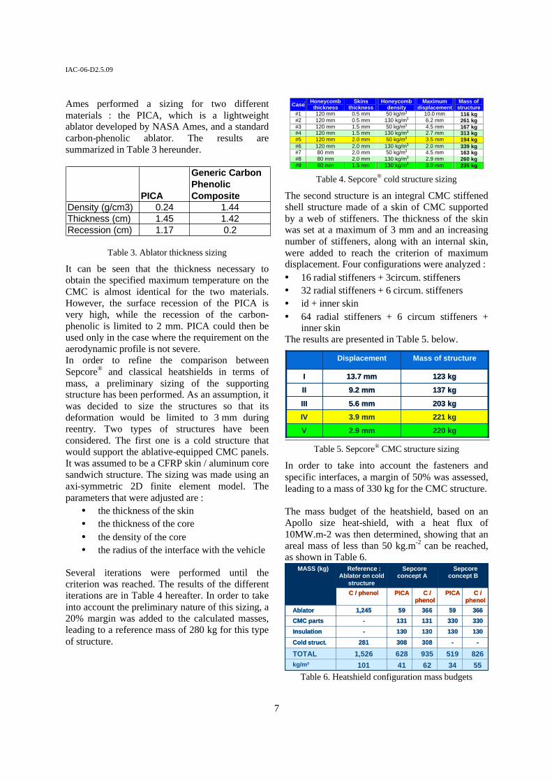
Deployable Decelerator Re-entry capsule sizes are usually limited by the launch system fairing capacity, which also obviously limits the aero-braking surface. To overcome this limit, use of deployable decelerators are ideal in certain flight regimes where it is necessary to increase deceleration of a capsule at high altitude by increasing the probe surface area and thereby providing a lowered probe ballistic coefficient. This is accomplished with the deployment of an outer hot-structure device (shown in Figure 16) that minimally increases the command module system mass, reduces aero-thermal heat loads experienced by the capsule thermal protection system, and consequently increases available vehicle payload.
Figure 16. Decelerator is deployed in space prior to re-entry by means of a deployment mechanism.
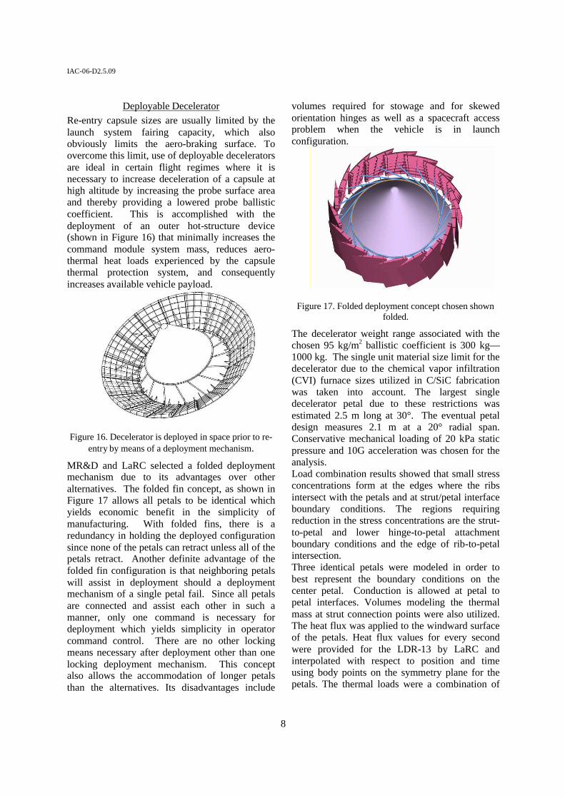
MR&D and LaRC selected a folded deployment mechanism due to its advantages over other alternatives. The folded fin concept, as shown in Figure 17 allows all petals to be identical which yields economic benefit in the simplicity of manufacturing. With folded fins, there is a redundancy in holding the deployed configuration since none of the petals can retract unless all of the petals retract. Another definite advantage of the folded fin configuration is that neighboring petals will assist in deployment should a deployment mechanism of a single petal fail. Since all petals are connected and assist each other in such a manner, only one command is necessary for deployment which yields simplicity in operator command control. There are no other locking means necessary after deployment other than one locking deployment mechanism. This concept also allows the accommodation of longer petals than the alternatives. Its disadvantages include
volumes required for stowage and for skewed orientation hinges as well as a spacecraft access problem when the vehicle is in launch configuration.
Figure 17. Folded deployment concept chosen shown folded.
The decelerator weight range associated with the chosen 95 kg/m2 ballistic coefficient is 300 kg—1000 kg. The single unit material size limit for the decelerator due to the chemical vapor infiltration (CVI) furnace sizes utilized in C/SiC fabrication was taken into account. The largest single decelerator petal due to these restrictions was estimated 2.5 m long at 30°. The eventual petal design measures 2.1 m at a 20° radial span. Conservative mechanical loading of 20 kPa static pressure and 10G acceleration was chosen for the analysis. Load combination results showed that small stress concentrations form at the edges where the ribs intersect with the petals and at strut/petal interface boundary conditions. The regions requiring reduction in the stress concentrations are the strut-to-petal and lower hinge-to-petal attachment boundary conditions and the edge of rib-to-petal intersection. Three identical petals were modeled in order to best represent the boundary conditions on the center petal. Conduction is allowed at petal to petal interfaces. Volumes modeling the thermal mass at strut connection points were also utilized. The heat flux was applied to the windward surface of the petals. Heat flux values for every second were provided for the LDR-13 by LaRC and interpolated with respect to position and time using body points on the symmetry plane for the petals. The thermal loads were a combination of
IAC-06-D2.5.09
9
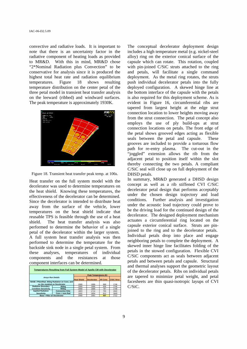
convective and radiative loads. It is important to note that there is an uncertainty factor in the radiative component of heating loads as provided to MR&D. With this in mind, MR&D chose “2*Nominal Radiation plus Convection” to be conservative for analysis since it is produced the highest total heat rate and radiation equilibrium temperatures. Figure 18 shows resulting temperature distribution on the center petal of the three petal model in transient heat transfer analysis on the leeward (ribbed) and windward surfaces. The peak temperature is approximately 1930K.
Figure 18. Transient heat transfer peak temp. at 106s.
Heat transfer on the full system model with the decelerator was used to determine temperatures on the heat shield. Knowing these temperatures, the effectiveness of the decelerator can be determined. Since the decelerator is intended to distribute heat away from the surface of the vehicle, lower temperatures on the heat shield indicate that reusable TPS is feasible through the use of a heat shield. The heat transfer analysis was also performed to determine the behavior of a single petal of the decelerator within the larger system. A full system heat transfer analysis was then performed to determine the temperature for the backside sink node in a single petal system. From these analyses, temperatures of individual components and the resistances at those component interfaces can be determined.
Heat Shield Decelerator Aft Cone C/SiC Strut
2068 1886 868 174645deg 2068 1886 836 174660deg 2068 1886 787 1746
Convective Only 1803 1714 755 1522Conv + nom Rad 1932 1804 812 1643
2068 1881 507 1712Base + Ribs on Decelerator
Peak Temperatures (K)
Radiative Boundary Condition Sensitivity
Temperatures Resulting from Full System Model of Apollo CM with Decelerator
Ansys Run Details
Applied Radiation Sensitivity
BASE: 2*NomRad, 30deg Radiation on Cone, and no ribs modeled on Decelerator
The conceptual decelerator deployment design includes a high temperature metal (e.g. nickel-steel alloy) ring on the exterior conical surface of the capsule which can rotate. This rotation, coupled with pin-joined C/SiC struts attached to the ring and petals, will facilitate a single command deployment. As the metal ring rotates, the struts push individual decelerator petals into the fully deployed configuration. A skewed hinge line at the bottom interface of the capsule with the petals is also required for this deployment scheme. As is evident in Figure 16, circumferential ribs are tapered from largest height at the edge strut connection location to lower heights moving away from the strut connection. The petal concept also employs the use of ply build-ups at strut connection locations on petals. The front edge of the petal shows grooved edges acting as flexible seals between the petal and capsule. These grooves are included to provide a torturous flow path for re-entry plasma. The cut-out in the “joggled” extension allows the rib from the adjacent petal to position itself within the slot thereby connecting the two petals. A compliant C/SiC seal will close up on full deployment of the DHSD petals. In summary, MR&D generated a DHSD design concept as well as a rib stiffened CVI C/SiC decelerator petal design that performs acceptably under the chosen design trajectory and load conditions. Further analysis and investigation under the acoustic load trajectory could prove to be the driving load for the continued design of the decelerator. The designed deployment mechanism actuates a circumferential ring located on the capsule exterior conical surface. Struts are pin-joined to the ring and to the decelerator petals. Individual petals drop into place and engage neighboring petals to complete the deployment. A skewed inner hinge line facilitates folding of the petals in the stowed configuration. Flexible CVI C/SiC components act as seals between adjacent petals and between petals and capsule. Structural and thermal analyses support the geometric layout of the decelerator petals. Ribs on individual petals are tapered to minimize petal weight, and petal facesheets are thin quasi-isotropic layups of CVI C/SiC.
IAC-06-D2.5.09
10
Health Monitoring System Acoustic Emission (AE) was identified as a candidate sensor technology for detecting and assessing impact damage on Thermal Protection System (TPS) components of future space vehicles as part of a Health Monitoring (HM) system. The AE technique utilizes an array of piezoelectric sensors mounted on the structure. Sound waves generated by damage mechanisms such as impact propagate through the structure and are detected by these sensors. Analysis of the time of arrival of the signals at different locations on the structure can be used to triangulate the position of the impact in a similar manner to that of locating an earthquake with seismic sensors. Further analysis of the signals can be used in attempts to assess the type and magnitude of damage based on correlating signals with a previously developed theoretical or experimental database of damage signals. Typically, sensors that detect in the ultrasonic frequency range are used to provide an improved signal to noise ratio as the background noise decreases with increasing frequency. In Phase I of this effort, a number of tasks were successfully performed to develop AE capabilities to support Phase II planned experimental impact testing on TPS coupons and subcomponents along with simulated impact testing of full scale TPS components during elevated temperature testing. The optimal locations for AE impact detection sensors were determined to be on the backup structural elements to which the TPS components would be attached. It was determined that the elevated operational temperatures of the actual TPS components would possibly exceed those permitted by currently available AE sensors. In addition, as TPS components might be removed and or replaced during multiple test cycles during Phase II, it was determined that the best operational scenario would be for the sensors to be mounted on the substructure.
Conclusion Although the project was prematurely cancelled due to a major restructuring of the Space Exploration Initiative, extensive concept design work has been performed on each of the three technological variants of the CMC based Thermal Protection System. This design task provided sufficient data to be able to compare the relative
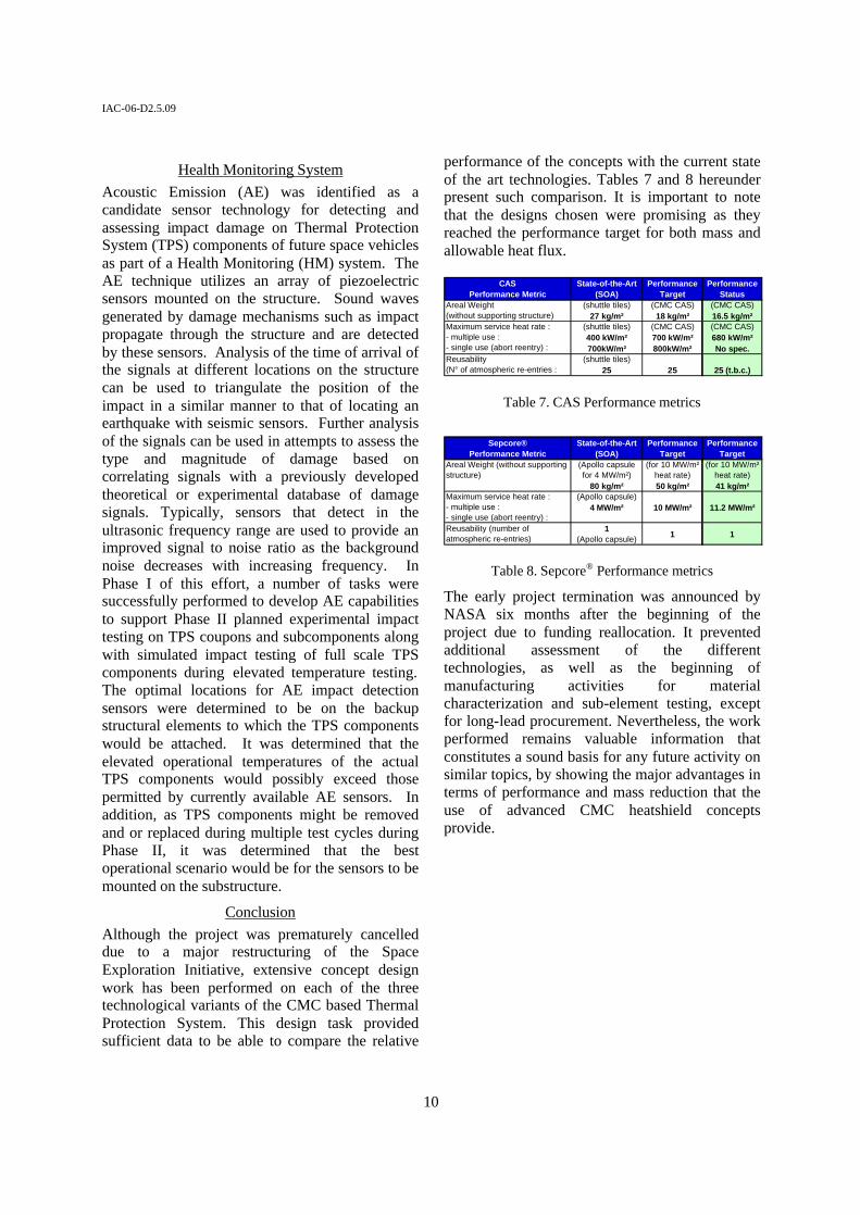
performance of the concepts with the current state of the art technologies. Tables 7 and 8 hereunder present such comparison. It is important to note that the designs chosen were promising as they reached the performance target for both mass and allowable heat flux.
CASPerformance Metric
State-of-the-Art (SOA)
PerformanceTarget
PerformanceStatus
Areal Weight(without supporting structure)
(shuttle tiles)27 kg/m²
(CMC CAS)18 kg/m²
(CMC CAS)16.5 kg/m²
Maximum service heat rate :- multiple use :- single use (abort reentry) :
(shuttle tiles)400 kW/m² 700kW/m²
(CMC CAS)700 kW/m²800kW/m²
(CMC CAS)680 kW/m²No spec.
Reusability(N° of atmospheric re-entries :
(shuttle tiles)25 25 25 (t.b.c.)
Table 7. CAS Performance metrics
Sepcore®
Performance MetricState-of-the-Art
(SOA)Performance
TargetPerformance
TargetAreal Weight (without supporting structure)
(Apollo capsulefor 4 MW/m²)
80 kg/m²
(for 10 MW/m²heat rate)50 kg/m²
(for 10 MW/m²heat rate)41 kg/m²
Maximum service heat rate :- multiple use :- single use (abort reentry) :
(Apollo capsule)4 MW/m² 10 MW/m² 11.2 MW/m²
Reusability (number of atmospheric re-entries)
1 (Apollo capsule) 1 1
Table 8. Sepcore® Performance metrics
The early project termination was announced by NASA six months after the beginning of the project due to funding reallocation. It prevented additional assessment of the different technologies, as well as the beginning of manufacturing activities for material characterization and sub-element testing, except for long-lead procurement. Nevertheless, the work performed remains valuable information that constitutes a sound basis for any future activity on similar topics, by showing the major advantages in terms of performance and mass reduction that the use of advanced CMC heatshield concepts provide.
IAC-06-D2.5.09
11
References 1. Snecma Propulsion Solide final report, ESR&T-SPS-TN-002-01, December 2005. 2. “Standard Test Method for Thermal Conductivity of Refractories,” Annual Book of ASTM Standards, Vol. 15.01, American Society of Testing and Materials, West Conshohocken, PA, 2000, pp. 54-59. 3. Daryabeigi, K., “Effective Thermal Conductivity of High Temperature Insulations for Reusable Launch Vehicles,” NASA TM-1999-208972, February 1999. 4. Daryabeigi, K., “Analysis and Testing of High Temperature Insulations for Reusable Launch Vehicles,” AIAA Paper 99-1044, January 1999.


![Heat and Thermal Energy Notes.ppt [Read-Only] - Yolasteeverphysics.yolasite.com/resources/Heat and Thermal Energy Note… · Title: Heat and Thermal Energy Notes.ppt [Read-Only] Author:](https://img.pdfslide.net/doc/110x75/5a8dcaa87f8b9abb068cbdb8/heat-and-thermal-energy-notesppt-read-only-and-thermal-energy-notetitle.jpg)