Embed Size (px)
Citation preview

1Copyright 2020 Adiuvo Engineering & Training, Ltd.
Integrating Arm Cortex-M Processors into Xilinx FPGAs
Course Workbook

Table of Contents
About this Workbook Page 3
Pre-Lab: Workshop Pre-requisites Page 4
Lab 1: Exploring the Architecture in Vivado Page 7
Lab 2: Saying Hello World Page 25
Lab 3: Completing a Simple Application Page 47
Copyright 2020 Adiuvo Engineering & Training, Ltd. 2

About this Workbook
This workbook is designed to be used in conjunction with the Integrating Arm Cortex-M processors in Xilinx FPGAs course.
The contents of this workbook are created by Adiuvo Engineering & Training, Ltd.
If you have any questions about the contents, or need assistance, please contact Adam Taylor at [email protected].
Copyright 2020 Adiuvo Engineering & Training, Ltd. 3
Pre-LabWorkshop Pre-requisites
Copyright 2020 Adiuvo Engineering & Training, Ltd. 4

Required HardwarePre-Lab
5Copyright 2020 Adiuvo Engineering & Training, Ltd.
The hands-on labs in this course use the following hardware:
• Digilent Arty S7-50 development board
• Digilent PmodNAV
• Digilent PmodHYGRO
• USB-A to Micro-B cable

Downloads and Installations
Vivado 2018.2
**Please check that it is this version and not a
newer version**
Download
Digilent Board Files Download
Arm Design Start FPGA IP
**Download Cortex-M1 for Xilinx**
Download
Arm Keil MDK Tools Download
Arm Keil Licensing Tool Download
Digilent Vivado IP – Master Branch Download
Pre-Lab
6Copyright 2020 Adiuvo Engineering & Training, Ltd.
Step 1 – Download and install the following at least 1 day prior to the workshop. This may take a
significant amount of time and drive space.

Lab 1Exploring the Architecture in Vivado
Copyright 2020 Adiuvo Engineering & Training, Ltd. 7

Lab 1: Exploring the Architecture in Vivado
8Copyright 2020 Adiuvo Engineering & Training, Ltd.
Step 1 - Ensure you have the following environment path variables set:
C:\Keil_v5\ARM\ARMCC\bin
C:\Xilinx\Vivado\2018.2\bin
Lab 1

Lab 1: Exploring the Architecture in Vivado
9Copyright 2020 Adiuvo Engineering & Training, Ltd.
Step 2 – Navigate to the directory containing the downloaded Arm M1 Core. This will be called
AT472-BU-98000-r0p1-00rel0.tgz.
Step 3 – Using a compression program (e.g., seven zip) unzip everything, including the inner
directory.
Lab 1

Lab 1: Exploring the Architecture in Vivado
10Copyright 2020 Adiuvo Engineering & Training, Ltd.
Step 4 – When extracted you should see the directory structure below.
Lab 1

Lab 1: Exploring the Architecture in Vivado
11Copyright 2020 Adiuvo Engineering & Training, Ltd.
Step 5 – If you have not installed the Digilent Board files already, copy the Digilent boards contained in
the directory below into <Vivado Install path>\Vivado\2018.2\data\boards\board_files
Lab 1

Lab 1: Exploring the Architecture in Vivado
12Copyright 2020 Adiuvo Engineering & Training, Ltd.
Step 6 – Open Vivado 2018.2. If you are familiar with Vivado do not do this by opening the project file.
Step 7 – Change the
directory using the TCL
console to:
cd C:\\<YOUR
DIRECTORY>\\AT472-
BU-98000-r0p1-00rel0
Lab 1

Lab 1: Exploring the Architecture in Vivado
13Copyright 2020 Adiuvo Engineering & Training, Ltd.
Step 8 – In the TCL Console enter the following command exec subst V: .
Make sure there is a space between “ : ” and “ . ”
This gets around the character limit on file paths in Windows by mapping the PWD to the V directory.
Using a file browser to explore the V directory should show this file structure:
Lab 1

Lab 1: Exploring the Architecture in Vivado
14Copyright 2020 Adiuvo Engineering & Training, Ltd.
Step 9 – The next thing we need to do is map in the IP repository. In Vivado click on Tools → Settings
Lab 1

Lab 1: Exploring the Architecture in Vivado
15Copyright 2020 Adiuvo Engineering & Training, Ltd.
Step 10 – In the dialog box select IP Defaults.
Lab 1

Lab 1: Exploring the Architecture in Vivado
16Copyright 2020 Adiuvo Engineering & Training, Ltd.
Step 11 – Select the Add IP
repository button (shown as a +).
Navigate to
V:\Vivado\Arm_IPI_Repository
Lab 1

Lab 1: Exploring the Architecture in Vivado
17Copyright 2020 Adiuvo Engineering & Training, Ltd.
Step 12 – We are now ready to open the project. Select File→Project→Open.
Navigate to V:/hardware/m1_for_arty_s7/m1_for_arty_s7
Select the project file m1_for_arty_s7.xpr
Lab 1

Lab 1: Exploring the Architecture in Vivado
18Copyright 2020 Adiuvo Engineering & Training, Ltd.
Step 13 – If you see a critical message
about simulation do not worry. Click on
Continue / OK.
To open the block diagram, select on
the > arrow next to the top level.
Lab 1

Lab 1: Exploring the Architecture in Vivado
19Copyright 2020 Adiuvo Engineering & Training, Ltd.
Step 14 – Double click on the
highlighted file. This will open the block
diagram.
Lab 1

Lab 1: Exploring the Architecture in Vivado
20Copyright 2020 Adiuvo Engineering & Training, Ltd.
Step 15 – If you want to pop out and explore the block diagram click on the button highlighted below.
You can examine the settings of the IP cores by double clicking on them, however, do not change anything.
Lab 1

Lab 1: Exploring the Architecture in Vivado
21Copyright 2020 Adiuvo Engineering & Training, Ltd.
Step 16 – The next step is to set up the software environment launch SDK by selecting File→Launch.
This will open a dialog, set the dialog as below in the diagram.
Lab 1
Lab 1: Exploring the Architecture in Vivado
22Copyright 2020 Adiuvo Engineering & Training, Ltd.
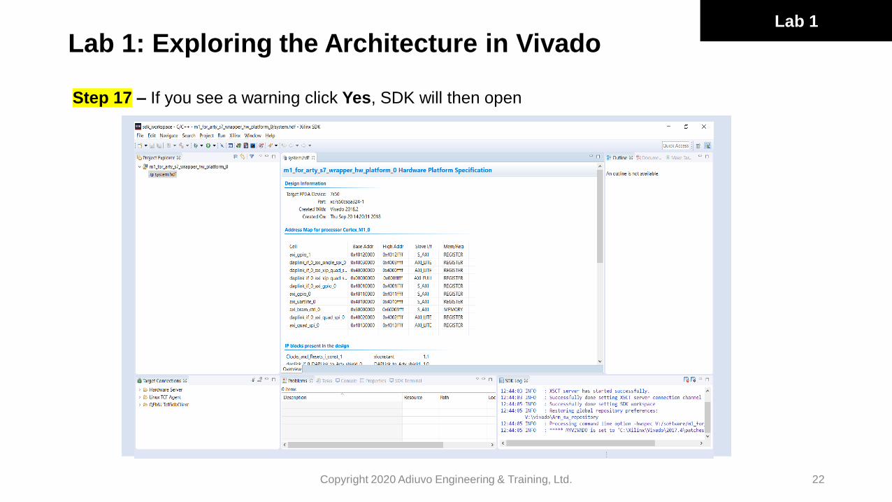
Step 17 – If you see a warning click Yes, SDK will then open
Lab 1

Lab 1: Exploring the Architecture in Vivado
23Copyright 2020 Adiuvo Engineering & Training, Ltd.
Step 18 – We need to add in the SW IP so that we can build the SW application correctly.
Select Xilinx→Repositories.
Lab 1

Lab 1: Exploring the Architecture in Vivado
24Copyright 2020 Adiuvo Engineering & Training, Ltd.
Step 19 – In the resultant dialog
select the following directory:
V:\Vivado\Arm_SW_repository
We are now ready to start using
our Arm Cortex-M1 system, this
completes Lab 1!
Lab 1

Lab 2Saying Hello World
Copyright 2020 Adiuvo Engineering & Training, Ltd. 25

Lab 2: Saying Hello World
26Copyright 2020 Adiuvo Engineering & Training, Ltd.
Step 1 – Wait for Vivado to complete the bitstream generation.
Lab 2

Lab 2: Saying Hello World
27Copyright 2020 Adiuvo Engineering & Training, Ltd.
Step 2 – Export the hardware definition select
File→Export→Export Hardware
Lab 2

Lab 2: Saying Hello World
28Copyright 2020 Adiuvo Engineering & Training, Ltd.
Step 3 – This will create a pop up. Select the
export location as V:\software
You do not need to include the bit stream
If you see the warning below click Yes.
Lab 2

Lab 2: Saying Hello World
29Copyright 2020 Adiuvo Engineering & Training, Ltd.
Step 4 – Next, we need to open XDSK. Select
File→Launch SDK
Lab 2

Lab 2: Saying Hello World
30Copyright 2020 Adiuvo Engineering & Training, Ltd.
Step 5 – In the pop up box, for the export location select the location we just exported the hardware
definition to (V:\Software) and select the workspace located at:
V:\software\m1_for_arty_s7\sdk_workspace
Lab 2

Lab 2: Saying Hello World
31Copyright 2020 Adiuvo Engineering & Training, Ltd.
Step 6 – Once SDK is opened, we will see the hardware definition imported into SDK. Note, the part
should show xc7S50. You will also see the address spaces for all of the added peripherals.
Lab 2

Lab 2: Saying Hello World
32Copyright 2020 Adiuvo Engineering & Training, Ltd.
Step 7 – The next step in SDK is to create a BSP, this will create APIs which enable us to work with the
peripherals included in the design. Select File→New→Board Support Package.
Lab 2

Lab 2: Saying Hello World
33Copyright 2020 Adiuvo Engineering & Training, Ltd.
Step 8 – In the next dialog leave the name as the automatically generated one and click Finish.
Lab 2
Lab 2: Saying Hello World
34Copyright 2020 Adiuvo Engineering & Training, Ltd.
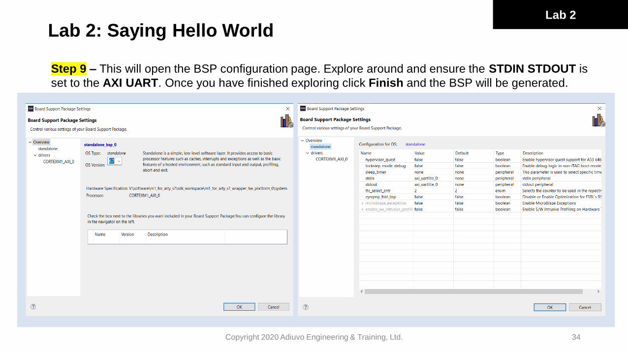
Step 9 – This will open the BSP configuration page. Explore around and ensure the STDIN STDOUT is
set to the AXI UART. Once you have finished exploring click Finish and the BSP will be generated.
Lab 2

Lab 2: Saying Hello World
35Copyright 2020 Adiuvo Engineering & Training, Ltd.
Step 10 – Once the BSP has finished generating you will notice a new MSS file opens in SDK, along
with a new project under the project explorer. This is the board support package. You can see the BSP
files and the APIs included in the design.
Lab 2

Lab 2: Saying Hello World
36Copyright 2020 Adiuvo Engineering & Training, Ltd.
Step 11 – Copy the files
Xpsuedo_asm_rvct.c
Xpseudo_asm_rvct.h
From V:\vivado\Arm_sw_repository\CortexM\bsp\standalone_v6_7\src\arm\cortexm1\armcc
Into V:\software\m1_for_arty_s7\sdk_workspace\standalone_bsp_0\CORTEXM1_AXI_0\include
Lab 2

Lab 2: Saying Hello World
37Copyright 2020 Adiuvo Engineering & Training, Ltd.
Step 12 – We now need to develop our SW application in Arm KEIL.
Navigate to V:/software/m1_for_arty_s7/Build_Keil/. Click on the file m1_for_arty_s7.uvprojx
This will open the Arm Keil project.
Lab 2

Lab 2: Saying Hello World
38Copyright 2020 Adiuvo Engineering & Training, Ltd.
Step 13 – Make sure the target is set to m1_for_arty_s7.
Open the Main directory under the project, and double click on main.c.
This will open the file for editing.
Lab 2
Step 14 – Scroll down to line 149 and change the output string from
print ("Example design for Digilent S7 board\r\n");
to
print (“Adiuvo Tutorial Example design for Digilent S7 board\r\n");

Lab 2: Saying Hello World
39Copyright 2020 Adiuvo Engineering & Training, Ltd.
Step 15 – Before we can click on Build, we need to check the name of the Arm Cortex processor
generated by SDK. Use a file explorer and navigate to
V:\software\m1_for_arty_s7\sdk_workspace\standalone_bsp_0
Ensure the folder is named CORTEX_M1_0 and not CORTEXM1_AXI_0 or similar, if they are, correct
the naming to CORTEX_M1_0.
Lab 2

Lab 2: Saying Hello World
40Copyright 2020 Adiuvo Engineering & Training, Ltd.
Step 16– Click on Build and you should see the project compile and produce necessary output files.
Lab 2

Lab 2: Saying Hello World
41Copyright 2020 Adiuvo Engineering & Training, Ltd.
Step 17– Use a file browser to navigate to V:\hardware\m1_for_arty_s7\m1_for_arty_s7. You will see
a files named bram_s7.elf and bram_s7.hex (these should have today’s time stamp as you just
generated them).
Lab 2

Lab 2: Saying Hello World
42Copyright 2020 Adiuvo Engineering & Training, Ltd.
Step 18 – Double click on the make_prog_files.bat this will create the bit file needed with the Cortex-
M1 and application we just created to download into the Arty S7-50 board.
Step 19 – In Vivado open Hardware Manager:
Lab 2

Lab 2: Saying Hello World
43Copyright 2020 Adiuvo Engineering & Training, Ltd.
Step 20 – Once Hardware Manager is open select Open Target and auto connect. This will open the
JTAG link with the target board.
Lab 2

Lab 2: Saying Hello World
44Copyright 2020 Adiuvo Engineering & Training, Ltd.
Step 21 – We are now connected to the Arty S7-50 board and can program it. Before we do this we
should open a terminal program, such as terra term or PuTTY, so we can see the output from the serial
link. Set it for 115200, 1 Start, 1 Stop no Parity.
Step 22 –To program the FPGA in Hardware Manager we need to select the correct bit file, select
Program Device.
Lab 2

Lab 2: Saying Hello World
45Copyright 2020 Adiuvo Engineering & Training, Ltd.
Step 23 – When the dialog appears select the file
V:/hardware/m1_for_arty_s7/m1_for_arty_s7/m1_for_arty_s7.bit
Lab 2

Lab 2: Saying Hello World
46Copyright 2020 Adiuvo Engineering & Training, Ltd.
Step 24 – Check the output in your terminal, it should look similar to below:
Lab 2
As we build on top of the existing reference design we can also press BTN1 and BTN0 on the Arty S7-50
to see LD0 and LD1 cycle through colors with each press.
This concludes Lab 2!

Lab 3Completing a Simple Application
Copyright 2020 Adiuvo Engineering & Training, Ltd. 47

Lab 3: Completing a Simple Application
48Copyright 2020 Adiuvo Engineering & Training, Ltd.
Step 1 – In Vivado we need to add in IP cores from the Digilent IP library. This requires that we first add
in the IP repository. To do this click on the Project Settings.
Lab 3

Lab 3: Completing a Simple Application
49Copyright 2020 Adiuvo Engineering & Training, Ltd.
Step 2 – This will open the project settings dialog box. Select IP→Repository and click on the + button
to add a IP repository.
Lab 3

Lab 3: Completing a Simple Application
50Copyright 2020 Adiuvo Engineering & Training, Ltd.
Step 3 – Navigate to the location of the Digilent IP library on your system (downloaded during the Pre-
Lab). If you do not have them they can be downloaded from https://github.com/Digilent/vivado-library.
Step 4 – When you see the dialog below click OK.
Lab 3

Lab 3: Completing a Simple Application
51Copyright 2020 Adiuvo Engineering & Training, Ltd.
Step 5 – We are now able to begin adding in the IP from this library into our Vivado design. The first
stage is to close the IP settings and open the block diagram. Float the block diagram so we can make
it fit the screen by selecting the button highlighted below.
Lab 3

Lab 3: Completing a Simple Application
52Copyright 2020 Adiuvo Engineering & Training, Ltd.
Step 6 – We are now going to add in the Pmod Nav and Pmod HYGRO. In the block diagram select
the + button. This will bring up a dialog which we can use to add in the necessary IP.
Lab 3

Lab 3: Completing a Simple Application
53Copyright 2020 Adiuvo Engineering & Training, Ltd.
Step 7 – To add Pmod Nav, in the search bar type
“pmodnav” and double click on the IP to add it into
the block diagram.
Step 8 – To add in the Pmod HYGRO, repeat steps
6-7 by clicking the + button again and in the search
bar type “pmodhygro” double click on the IP to
add it into the block diagram.
Lab 3

Lab 3: Completing a Simple Application
54Copyright 2020 Adiuvo Engineering & Training, Ltd.
Step 9 – Check that both the IP blocks have now been added in the block diagram.
Lab 3

Lab 3: Completing a Simple Application
55Copyright 2020 Adiuvo Engineering & Training, Ltd.
Step 10 – Click on the Run Connection Automation option. This will open a dialog to connect in the
newly added IP.
Lab 3

Lab 3: Completing a Simple Application
56Copyright 2020 Adiuvo Engineering & Training, Ltd.
Step 11 – In the dialog check All Automation and click OK.
Lab 3

Lab 3: Completing a Simple Application
57Copyright 2020 Adiuvo Engineering & Training, Ltd.
Step 12 – You will see the updated block diagram with the PmodNAV and PmodHYGRO connected
into the AXI system and with the Cortex-M1 processor.
Lab 3

Lab 3: Completing a Simple Application
58Copyright 2020 Adiuvo Engineering & Training, Ltd.
Step 12 (cont’d) – Make sure you connect the ext_spi_clk to the s_axi_clk
Lab 3

Lab 3: Completing a Simple Application
59Copyright 2020 Adiuvo Engineering & Training, Ltd.
Step 13 – At this point we have not added any IO to these IP blocks connecting them to the Pmod ports
on the Arty S7-50.
The next thing to do is select the Connector JB under the board tab and drag and drop it on the
PmodHYGRO.
Lab 3
Lab 3: Completing a Simple Application
60Copyright 2020 Adiuvo Engineering & Training, Ltd.
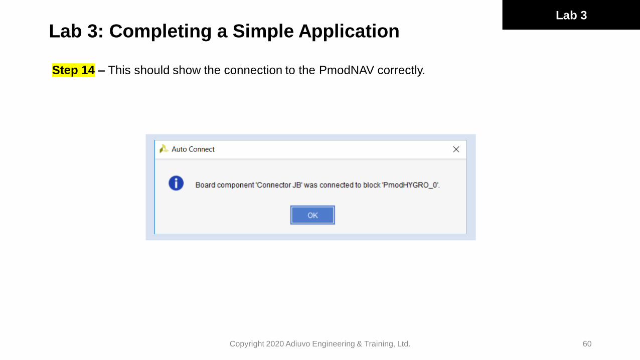
Step 14 – This should show the connection to the PmodNAV correctly.
Lab 3

Lab 3: Completing a Simple Application
61Copyright 2020 Adiuvo Engineering & Training, Ltd.
Step 15 – Repeat the same thing for PmodNAV and Connector JA.
Lab 3

Lab 3: Completing a Simple Application
62
Copyright 2020 Adiuvo Engineering & Training, Ltd.
Step 16 – Again, you will see a confirmation of the connection.
Lab 3

Lab 3: Completing a Simple Application
63Copyright 2020 Adiuvo Engineering & Training, Ltd.
Step 17 – We now check assigned memory addresses. Save and close the block diagram and double
check in the Address Editor that all of the Pmods are in the 0x4xxx_xxxx Range.
Lab 3

Lab 3: Completing a Simple Application
64Copyright 2020 Adiuvo Engineering & Training, Ltd.
Step 18 – We are now ready to build the design. Click on the validate button to prove we have no
errors or critical warnings in the design.
Lab 3

Lab 3: Completing a Simple Application
65Copyright 2020 Adiuvo Engineering & Training, Ltd.
Step 19 – Click on the generate bit stream button.
Lab 3

Lab 3: Completing a Simple Application
66Copyright 2020 Adiuvo Engineering & Training, Ltd.
Step 20 – This may take a little while but once the bit stream is completed you will see the message
write_bitstream_complete in the upper right hand corner of Vivado.
Lab 3
Lab 3: Completing a Simple Application
67Copyright 2020 Adiuvo Engineering & Training, Ltd.
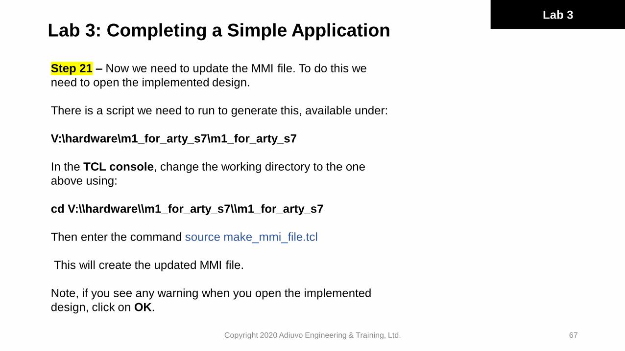
Step 21 – Now we need to update the MMI file. To do this we
need to open the implemented design.
There is a script we need to run to generate this, available under:
V:\hardware\m1_for_arty_s7\m1_for_arty_s7
In the TCL console, change the working directory to the one
above using:
cd V:\\hardware\\m1_for_arty_s7\\m1_for_arty_s7
Then enter the command source make_mmi_file.tcl
This will create the updated MMI file.
Note, if you see any warning when you open the implemented
design, click on OK.
Lab 3

Lab 3: Completing a Simple Application
68Copyright 2020 Adiuvo Engineering & Training, Ltd.
Step 22 – Next, export the hardware definition. Select File→Export→Export Hardware.
Lab 3

Lab 3: Completing a Simple Application
69Copyright 2020 Adiuvo Engineering & Training, Ltd.
Step 23 – In the pop up, set the export location as V:\software
Lab 3

Lab 3: Completing a Simple Application
70Copyright 2020 Adiuvo Engineering & Training, Ltd.
Step 24 – In the pop up, set the
export location as V:\software.
If you see a warning asking if you
want to overwrite the existing file,
click Yes.
Lab 3

Lab 3: Completing a Simple Application
71Copyright 2020 Adiuvo Engineering & Training, Ltd.
Step 25 – Next, we need to open XDSK. Select File→Launch SDK.
Lab 3

Lab 3: Completing a Simple Application
72Copyright 2020 Adiuvo Engineering & Training, Ltd.
Step 26 – In the pop up box, for the export location, select the location we just exported the hardware
definition to (V:\Software).
Select the workspace located at V:\software\m1_for_arty_s7\sdk_workspace.
Note: Use File Explorer to confirm there is only one exported hardware definition under V:\software.
If there is a HDF file for the Arty A7, please delete it.
Lab 3

Lab 3: Completing a Simple Application
73Copyright 2020 Adiuvo Engineering & Training, Ltd.
Step 27 – In SDK you will see the hardware
definition and BSP being updated from what
we used in Lab 2. Under the BSP delete the
directory cortexm1_0.
In the hardware definition you will see the
PmodHYGRO and PmodNAV.
Lab 3
In the BSP MSS file you will also see the drivers have been included with the BSP.

Lab 3: Completing a Simple Application
74Copyright 2020 Adiuvo Engineering & Training, Ltd.
Step 28 – Next, we need to copy the files
Xpsuedo_asm_rvct.c and Xpseudo_asm_rvct.h
From
V:\vivado\Arm_sw_repository\CortexM\bsp\standalone_v6_7\src\arm\cortexm1\armcc
to
V:\software\m1_for_arty_s7\sdk_workspace\standalone_bsp_0\CORTEXM1_AXI_0\include
Lab 3
Step 29 – Check the name of the Cortex-M processor generated by SDK. Use File Explorer and navigate to
V:\software\m1_for_arty_s7\sdk_workspace\standalone_bsp_0.
Ensure the folder is named CORTEX_M1_0 and not CORTEXM1_AXI_0 or similar, if so correct the naming to
CORTEX_M1_0.

Lab 3: Completing a Simple Application
75Copyright 2020 Adiuvo Engineering & Training, Ltd.
Step 30 – Now, let’s develop our SW application in Arm KEIL.
Navigate to V:/software/m1_for_arty_s7/Build_Keil/. Click on the file m1_for_arty_s7.uvprojx.
This will open the Arm Keil project.
Lab 3
Make sure the target is set to m1_for_arty_s7.

Lab 3: Completing a Simple Application
76Copyright 2020 Adiuvo Engineering & Training, Ltd.
Step 31 – The next thing we need to do is ensure
the compiler directives are set correctly for both our
application and the drivers we will be using. To
open the options, click on the highlighted button.
Ensure Optimization is set to Level-1 (O-1), C99 and GNU extensions are enabled, if you want you can also select the optimization level.
Lab 3

Lab 3: Completing a Simple Application
77Copyright 2020 Adiuvo Engineering & Training, Ltd.
Step 32 – To work with the PmodHYGRO and the PmodNAV we need to add in the source code.
To do this we right click on the project and select Manage Project Items.
Lab 3

Lab 3: Completing a Simple Application
78Copyright 2020 Adiuvo Engineering & Training, Ltd.
Step 33 – Under Groups we can add in the
PModHYGRO and the PModNAV as new
groups.
Then add in the source code which can be
found under the PmodXXXX drivers directory.
Find the drivers under:
V:\software\m1_for_arty_s7\sdk_workspace\
standalone_bsp_0\CORTEX_M1_0\libsrc
For the PmodNAV do not include the SPI
source files. These are already included under
the Xilinx_SPI group
Lab 3

Lab 3: Completing a Simple Application
Step 34 – Open the PmodNAV.c and comment out usleep() calls.
Open xtmrctr_sinit.c under the Xilinx PmodHYGRO and edit the line to be XTmrCtr_ConfigXTmrCtr_ConfigTable[1];
Copyright 2020 Adiuvo Engineering & Training, Ltd. 79
Lab 3

Lab 3: Completing a Simple Application
80Copyright 2020 Adiuvo Engineering & Training, Ltd.
Step 35 – We can then use the Pmods and create applications. In this example, let’s create a simple
application which reads the Pmods and Temperature, Humidity, X,Y & Z information over the terminal
by adding the following into our code in main.c:
#include "PmodHYGRO.h"
#include "PmodNAV.h"
#define TIMER_FREQ_HZ 100000000
PmodHYGRO myDevice;
PmodNAV nav;
bool sample;
float temp_degc, hum_perrh, temp_degf;
The above should be declared as global variables
Lab 3

Lab 3: Completing a Simple Application
81Copyright 2020 Adiuvo Engineering & Training, Ltd.
Step 36 – To provide a timing reference you might want to use the system tick. This can be
accessed by
#define STCTRL (*( ( volatile unsigned long *) 0xE000E010 ))
#define STRELOAD (*( ( volatile unsigned long *) 0xE000E014 ))
#define STCURR (*( ( volatile unsigned long *) 0xE000E018 ))
#define SBIT_ENABLE 0
#define SBIT_TICKINT 1
#define SBIT_CLKSOURCE 2
#define RELOAD_VALUE 98999999
The ISR can be accessed using
void SysTick_Handler(void)
{
sample=TRUE;
}
This is already mapped into the vector. Check out startup_arty_cm1.s.
Lab 3

Lab 3: Completing a Simple Application
82Copyright 2020 Adiuvo Engineering & Training, Ltd.
Step 37 – In the main loop add in the following code
HYGRO_begin(&myDevice,XPAR_PMODHYGRO_0_AXI_LITE_IIC_BASEADDR,0x40,XPAR_PMODHYGRO_0_AXI
_LITE_TMR_BASEADDR,1,TIMER_FREQ_HZ);
NAV_begin
(&nav,XPAR_PMODNAV_0_AXI_LITE_GPIO_BASEADDR,XPAR_PMODNAV_0_AXI_LITE_SPI_BASEADDR);
NAV_Init(&nav);
STRELOAD = RELOAD_VALUE;
STCTRL = (1<<SBIT_ENABLE) | (1<<SBIT_TICKINT) | (1<<SBIT_CLKSOURCE);
while ( 1 )
{
if (sample == TRUE){
temp_degc = HYGRO_getTemperature(&myDevice);
hum_perrh = HYGRO_getHumidity(&myDevice);
sprintf (debugStr, "Temp is %f Humidity is %f\r\n\n", temp_degc, hum_perrh );
print ( debugStr );
NAV_GetData(&nav);
sprintf (debugStr, "X is %f Y is %f Z is %f\r\n\n", nav.acclData.X, nav.acclData.Y, nav.acclData.Z );
print ( debugStr );
sample = FALSE;
}
}
Lab 3

Lab 3: Completing a Simple Application
83Copyright 2020 Adiuvo Engineering & Training, Ltd.
Step 38 – The expected output should produce something like below
Lab 3

Lab 3: Completing a Simple Application
84Copyright 2020 Adiuvo Engineering & Training, Ltd.
Step 39 – Now, let’s test our application on the
hardware.
Use a file browser navigate to
V:\hardware\m1_for_arty_s7\m1_for_arty_s7.
You will see a file named bram_s7.elf and
bram_s7.hex. These should have today’s time
stamp as you just generated them.
Lab 3

Lab 3: Completing a Simple Application
85Copyright 2020 Adiuvo Engineering & Training, Ltd.
Step 40 – Double click on make_prog_files.bat
This will create the bit file needed with the Cortex-M1 and application we just created to download
into the Arty S7-50 board.
Step 41 – Power off the Arty S7 board and connect the PmodNAV to PmodA and PmodHYGRO to
PmodB.
Lab 3

Lab 3: Completing a Simple Application
Step 42 – Power on the Arty Board and In Vivado open the Hardware Manager.
Copyright 2020 Adiuvo Engineering & Training, Ltd. 86
Lab 3

Lab 3: Completing a Simple Application
87Copyright 2020 Adiuvo Engineering & Training, Ltd.
Step 43 – Once Hardware Manager is open, select Open Target and auto connect. This will open
the JTAG link with the target board.
Lab 3

Lab 3: Completing a Simple Application
88Copyright 2020 Adiuvo Engineering & Training, Ltd.
Step 44 – This will connect to the Arty S7-50 so that we can program it. Before we do this we
should open a terminal program (such as terra term or PuTTY) so that we can see the output from
the serial link.
Set it for 115200, 1 Start, 1 Stop no Parity.
Lab 3

Lab 3: Completing a Simple Application
89Copyright 2020 Adiuvo Engineering & Training, Ltd.
Step 45 – To program the FPGA in Hardware Manager we need to select the correct bit file. Select
Program Device.
Lab 3

Lab 3: Completing a Simple Application
90Copyright 2020 Adiuvo Engineering & Training, Ltd.
Step 46 – When the dialog appears, select the file
V:/hardware/m1_for_arty_s7/m1_for_arty_s7/m1_for_arty_s7.bit
Lab 3
Step 47 – Check the output in your terminal.
Congratulations! You have finished Lab 3 and completed your simple application.

©2020 Excelpoint Technology Ltd. All rights reserved.
Excelpoint Systems (Pte) Ltd
15 Changi Business Park Central 1
#06-00 Singapore 486057
T +65 6741 8966
F +65 6741 8980
www.excelpoint.com
Contact Persons:
Product Marketing (ASEAN, India & ANZ)
Name Joseph Chiam