Embed Size (px)
Citation preview

Integrating Lenz and MERG DCC
with home-designed Control Software
Author Mark PatrickMERG M1701
April 2008

About Me
• Interested in model railwaysfrom an early age! Have built a number of OO gauge layouts and one in N gauge.
• Work as an Engineer for theBBC, designing broadcastautomation and controlsystems and control rooms.
• One of the owners of MJT& Dart Castings.

About My Layout - Tedford & Bearham
• OO Gauge, mainly modern image.
• Approx 14ft by 7ft in loft conversion room.
• 2 track main line, main station with 5 platforms, branch station with 3 platforms, 13 storage lines.

Design Criteria
• Had to presentable and easy to access for visitors.
• Had to have plenty of storage for locos and stock
• Had to allow continuous running with easy ability to change trains.
• Had to have computer control of points and signals.
• Had to have a large station to take 8 coach trains and a smaller branch line station.
• Had to make best use of available space.

Track Plan
• 13 Storage tracks are actually hidden under Bearham station.
• Numbers in boxes are button numbers for control system.
• Numbers adjacent to points are DCC accessory numbers.
• Numbers adjacent to signals are signal numbers for control system.
• There are 3 double slips and 1 single slip.
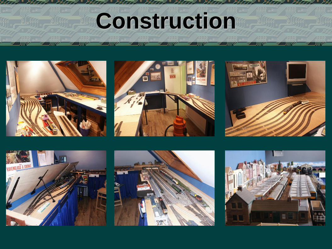
Construction

Control Architecture Diagram

Control Architecture 1
• Built around a Lenz 100 System with computer interface.
• Points driven by MERG and Lenz Decoders.
• Signals driven by MERG Decoders and Relays.
• Trains driven by 2 Lenz LS100 Throttles or PC.
• Track Detection via Lenz RS bus to PC.
• Pulled together by Computer running VB control application custom designed for layout.
• Visibility of storage lines via camera to PIP input on computer monitor, lighting via Ikea LED strips.

Control Architecture 2
• Point control is via route settings, similar to Entry-Exit switching. This can be done from the screen or using a control panel that is interface via USB.
• Signalling follows set routes and occupancy so it appears to operate realistically. There is no interlocking so trains can pass red signals!
• The DCC track feed is divided into three power districts.

Control Figures
• 44 points controlled via 2 Lenz Decoders & 8 MERG Decoders driving Peco and SEEP motors.
• 26 occupancy blocks via 2 LDT detectors & 3 Lenz LR101/LB101 detectors – will be 28 blocks when Lenz LB101s become available again!
• 5 MERG accessory decoders drive 40 relays to control signals and lighting.
• 15 Three Aspect signals.
• Over 70 DCC chipped locos, mainly Lenz but some TCS, ESU & ZTC.
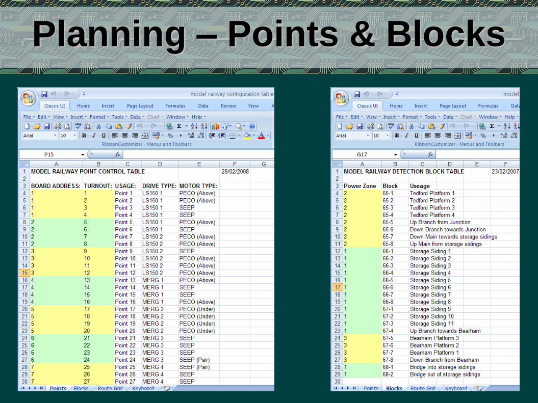
Planning – Points & Blocks

Planning - Routes
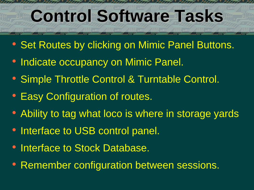
Control Software Tasks
• Set Routes by clicking on Mimic Panel Buttons.
• Indicate occupancy on Mimic Panel.
• Simple Throttle Control & Turntable Control.
• Easy Configuration of routes.
• Ability to tag what loco is where in storage yards
• Interface to USB control panel.
• Interface to Stock Database.
• Remember configuration between sessions.

Control Software Screen Shot:Full Screen with PIP

Control Software Screen Shot:Close Up of Mimic Diagram
Solid = RoutedDashed = Unrouted
White = UnoccupiedMagenta = Occupied
This shows routesas follows:
• Tedford Platform 1 to storage line 4
• Tedford Platform 4 to storage line 13
• Bearham Platform 3to Up Branch
• (Partial route from Storage line 6 to TedfordPlatform 2)
Signal aspects also shown

Control Software Screen Shot:Close Up of Config mode
Route from Button 1 to Button 4 (Storage 3 to Tedford Platform 1)

Control Software Configuration:rail.ini Configuration File
• Holds basic configuration
• Holds keyboard shortcuts for each route button

Control Software Configuration:signals.ini Configuration File
• Holds base DCC address for each signals –converts signal addresses to DCC addresses
• Each Signal uses 2 DCC addresses & relays –first is Red or NOT Red, the second is Yellow or Green.
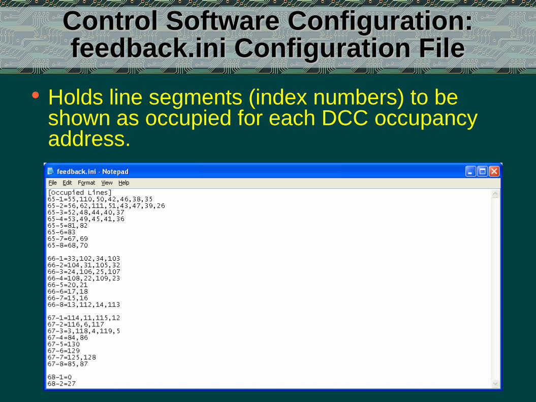
Control Software Configuration:feedback.ini Configuration File
• Holds line segments (index numbers) to be shown as occupied for each DCC occupancy address.

Control Software Configuration:buttons.ini Configuration File
• Holds a list of buttons which are valid destinations for each button. One line per button.
• First selected button goes orange, destinations go yellow – this decides which buttons go yellow.
• Also holds LED mappings for each button.

Control Software Configuration:routes.ini Configuration File (1)
• Route Rules• One entry denotes line segments to set as solid when
making the route.• The other entry denotes line segments to clear when
making the router.
• Routes are always made form lower button number to higher button number.

Control Software Configuration:routes.ini Configuration File (2)
• Route Points• Denotes points to set for the route. Positive for outer
route, negative for inner route (from inside layout).• Entries such as #1:13 mean ‘do route points for route
1:13 – allows routes to be concatenated.
• Routes are always made form lower button number to higher button number.

Control Software Configuration:status.ini Configuration File
• Holds two status integers for each line segment. • Colour (to indicate occupied or not)• Style (to indicate routed or not).
• Read every time screen is refreshed, including when program starts, written to on status change.
• Also holds occupancy tags for storage lines.

Control Software Limitations
• Doesn’t know which train is where – RFID?
• Can’t automatically stop trains at signals.
• Doesn’t detect manual point changes or confirm points have actually switched.
• Mimic Panel is custom designed, but designer capability could add as a future development.
• No direct implementation (yet) of multiple control over TCP/IP.
• Configuration Files are INI files rather than XML.
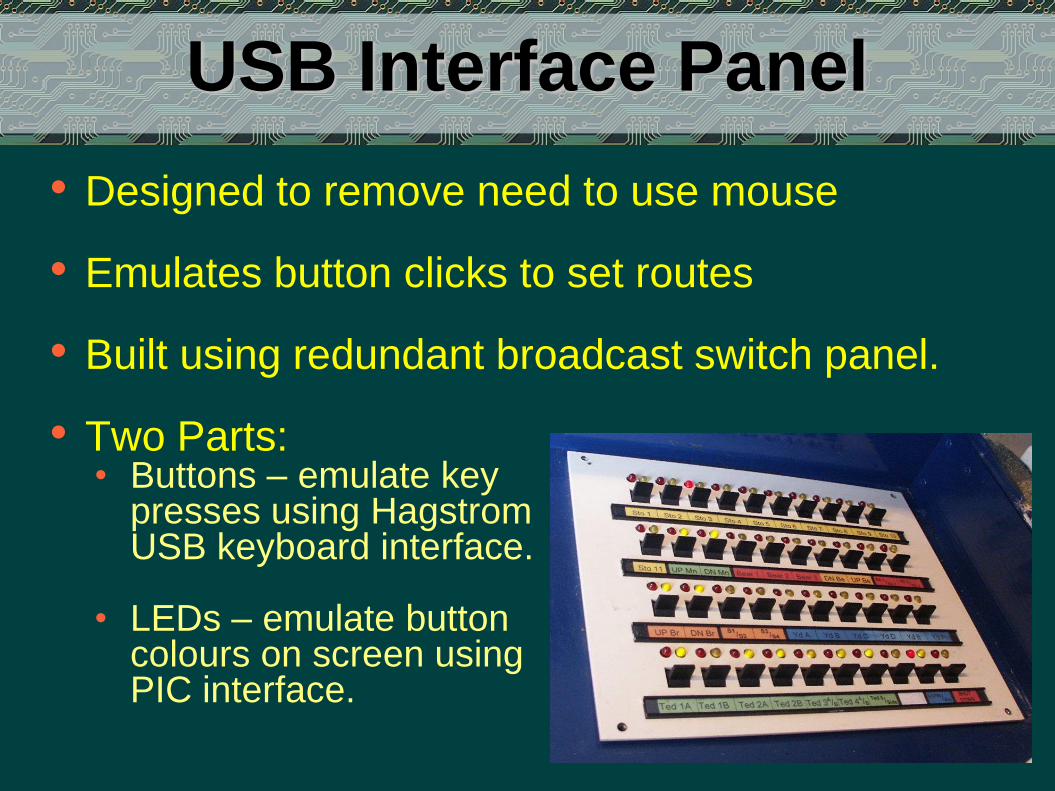
USB Interface Panel
• Designed to remove need to use mouse
• Emulates button clicks to set routes
• Built using redundant broadcast switch panel.
• Two Parts:• Buttons – emulate key
presses using HagstromUSB keyboard interface.
• LEDs – emulate buttoncolours on screen usingPIC interface.

USB Panel - Switches
• 40 switches on panel, all 2 way = 80 possible options, wired in a matrix to Hagstrom encoder.
• Each option given a key press, linked to a button in rail.ini
• Key press setupusing Hagstrom configuration utility.
• No need for USB drivers – appears as a normal keyboard to PC.

USB Panel - LEDs
• 80 LEDs on panel, 1 red + 1 yellow per switch.
• Interfaced via USB PIC from Velleman 8055 Kit.
• Matrix Drive via a second PIC chip.
• Velleman 8055 kit gives very simply interface via USB but is relatively slow. It has analogue I/O as well which I have not used in this application.
• When a button is pressed, software sends instructions to switch on LEDs (red for source, yellow for destination) as mapped in buttons.ini.

USB Panel – Circuit Diagram

Signals
• Mainly Eckon/Berko 3 Aspect Signals
• Driven via 2 accessoryoutputs & 2 relays persignal – simple butvery reliable.
• Theatre Indicator
• SMD 7-Segment Display
• Wired with fine kynar wire
• Driven via diode matrix - one logic input per display option
• Can display 1,2,3,4,5 and b
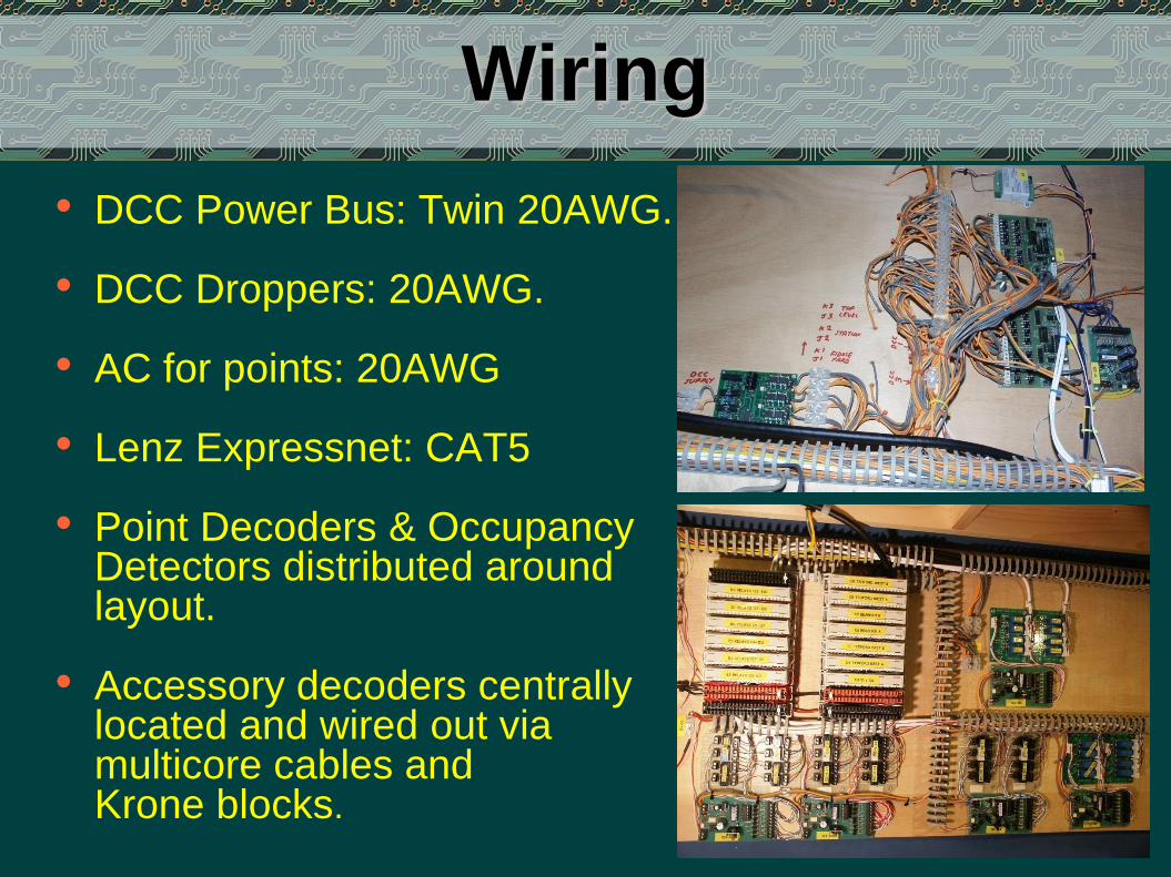
Wiring
• DCC Power Bus: Twin 20AWG.
• DCC Droppers: 20AWG.
• AC for points: 20AWG
• Lenz Expressnet: CAT5
• Point Decoders & Occupancy Detectors distributed around layout.
• Accessory decoders centrally located and wired out via multicore cables and Krone blocks.
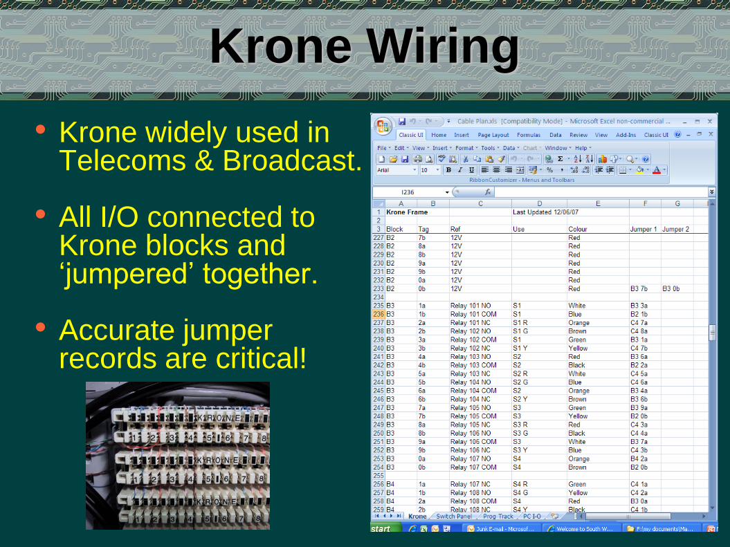
Krone Wiring
• Krone widely used inTelecoms & Broadcast.
• All I/O connected toKrone blocks and ‘jumpered’ together.
• Accurate jumper records are critical!

The Wiring ‘Frame’

Tedford Station

Tedford Depot

Diesels at Tedford

Bearham & Control Desk

Bearham Shed

Bearham Station

Bearham Yard

The End
Thank you for listening
Any questions?
See www.padsrocks.com/tedford
(and of course www.dartcastings.com !)