Embed Size (px)
Citation preview

AN2088Rev. 0, 3/2001
Integrating the DSP563xx inDistributed Computing
EnvironmentsApplication Note
by
Mihai V. MICEA,Mircea TRIFU
and Adrian TRIFU
Fre
esc
ale
Se
mic
on
du
cto
r, I
For More Information On This Product, Go to: www.freescale.com
nc
...
Freescale Semiconductor
© Freescale Semiconductor, Inc., 2004. All rights reserved.

Fre
esc
ale
Se
mic
on
du
cto
r, I
Freescale Semiconductor, Inc.
For More Information On This Product, Go to: www.freescale.com
nc
...

Abstract and Contents
Distributed digital signal processing is the most suitable solution for many real-life applications involving digital data acquisition and processing from multiple signal sources scattered over large areas. The advantages of distributed computing over single-processor or other multi-processor architectures include high computing power at a low cost, flexibility, and scalability.
Several ways to implement distributed digital signal processing exist, each with certain strengths and weaknesses. Choosing the optimum implementation for a particular application is often difficult, depending largely on the requirements of the application.
This paper proposes a hardware and software structure for distributed digital signal processing which offers flexibility and scalability for many real-life applications.
1 Introduction . . . . . . . . . . . . . . . . . . . . . . . . . . . . . . . . . . . . . . . . . . . . . . . . . . . . . . . . . . 1
1.1 Architecture . . . . . . . . . . . . . . . . . . . . . . . . . . . . . . . . . . . . . . . . . . . . . . . . . . . . . . . . . . . . 11.2 Communication. . . . . . . . . . . . . . . . . . . . . . . . . . . . . . . . . . . . . . . . . . . . . . . . . . . . . . . . . . 21.3 Monitor Program. . . . . . . . . . . . . . . . . . . . . . . . . . . . . . . . . . . . . . . . . . . . . . . . . . . . . . . . . 31.4 High-Level Software. . . . . . . . . . . . . . . . . . . . . . . . . . . . . . . . . . . . . . . . . . . . . . . . . . . . . . 3
2 Workstation-DSP Communication Protocol . . . . . . . . . . . . . . . . . . . . . . . . . . . . . 3
2.1 The Command Protocol . . . . . . . . . . . . . . . . . . . . . . . . . . . . . . . . . . . . . . . . . . . . . . . . . . . 42.2 Communication Library Functions Overview . . . . . . . . . . . . . . . . . . . . . . . . . . . . . . . . . . 52.2.1 Low-Level Functions . . . . . . . . . . . . . . . . . . . . . . . . . . . . . . . . . . . . . . . . . . . . . . . . . . 62.2.1.1 scom_init. . . . . . . . . . . . . . . . . . . . . . . . . . . . . . . . . . . . . . . . . . . . . . . . . . . . . . . . . 62.2.1.2 scom_shut_down . . . . . . . . . . . . . . . . . . . . . . . . . . . . . . . . . . . . . . . . . . . . . . . . . . 72.2.1.3 scom_write_buf . . . . . . . . . . . . . . . . . . . . . . . . . . . . . . . . . . . . . . . . . . . . . . . . . . . 72.2.1.4 scom_read_buf . . . . . . . . . . . . . . . . . . . . . . . . . . . . . . . . . . . . . . . . . . . . . . . . . . . . 72.2.1.5 mdps_get_error . . . . . . . . . . . . . . . . . . . . . . . . . . . . . . . . . . . . . . . . . . . . . . . . . . . . 82.2.2 High-Level Functions . . . . . . . . . . . . . . . . . . . . . . . . . . . . . . . . . . . . . . . . . . . . . . . . . . 82.2.2.1 scsom_reset_dsp . . . . . . . . . . . . . . . . . . . . . . . . . . . . . . . . . . . . . . . . . . . . . . . . . . . 82.2.2.2 scsom_run . . . . . . . . . . . . . . . . . . . . . . . . . . . . . . . . . . . . . . . . . . . . . . . . . . . . . . . . 82.2.2.3 scom_load_program . . . . . . . . . . . . . . . . . . . . . . . . . . . . . . . . . . . . . . . . . . . . . . . . 82.2.2.4 scom_write_dsp . . . . . . . . . . . . . . . . . . . . . . . . . . . . . . . . . . . . . . . . . . . . . . . . . . . 92.2.2.5 Helper Functions. . . . . . . . . . . . . . . . . . . . . . . . . . . . . . . . . . . . . . . . . . . . . . . . . . . 9
3 The DSP56307 in a Distributed Environment . . . . . . . . . . . . . . . . . . . . . . . . . . . . 9
3.1 General Description of the Monitor Program . . . . . . . . . . . . . . . . . . . . . . . . . . . . . . . . . . 103.2 Monitor Program Implementation on DSP56307. . . . . . . . . . . . . . . . . . . . . . . . . . . . . . . 113.2.1 Definitions . . . . . . . . . . . . . . . . . . . . . . . . . . . . . . . . . . . . . . . . . . . . . . . . . . . . . . . . . 123.2.2 Initialization . . . . . . . . . . . . . . . . . . . . . . . . . . . . . . . . . . . . . . . . . . . . . . . . . . . . . . . . 133.2.3 Receive Routine . . . . . . . . . . . . . . . . . . . . . . . . . . . . . . . . . . . . . . . . . . . . . . . . . . . . . 14
Abstract and Contents
Fre
esc
ale
Se
mic
on
du
cto
r, I
Freescale Semiconductor, Inc.
For More Information On This Product, Go to: www.freescale.com
nc
...

Integrating the DSP563xx in Distributed Computing Environments
3.2.4 Load Procedure . . . . . . . . . . . . . . . . . . . . . . . . . . . . . . . . . . . . . . . . . . . . . . . . . . . . . . 153.2.5 Run Command Procedure . . . . . . . . . . . . . . . . . . . . . . . . . . . . . . . . . . . . . . . . . . . . . . 163.2.6 Transmit Routine . . . . . . . . . . . . . . . . . . . . . . . . . . . . . . . . . . . . . . . . . . . . . . . . . . . . 18
4 Case Study . . . . . . . . . . . . . . . . . . . . . . . . . . . . . . . . . . . . . . . . . . . . . . . . . . . . . . . . . . 20
4.1 General Architecture. . . . . . . . . . . . . . . . . . . . . . . . . . . . . . . . . . . . . . . . . . . . . . . . . . . . . 204.1.1 Controlling Computer . . . . . . . . . . . . . . . . . . . . . . . . . . . . . . . . . . . . . . . . . . . . . . . . . 204.1.2 Workstation. . . . . . . . . . . . . . . . . . . . . . . . . . . . . . . . . . . . . . . . . . . . . . . . . . . . . . . . . 214.1.3 DSP-Based Board . . . . . . . . . . . . . . . . . . . . . . . . . . . . . . . . . . . . . . . . . . . . . . . . . . . . 224.2 DSP Algorithms . . . . . . . . . . . . . . . . . . . . . . . . . . . . . . . . . . . . . . . . . . . . . . . . . . . . . . . . 234.2.1 Adder Algorithm. . . . . . . . . . . . . . . . . . . . . . . . . . . . . . . . . . . . . . . . . . . . . . . . . . . . . 234.2.2 FFT Algorithm . . . . . . . . . . . . . . . . . . . . . . . . . . . . . . . . . . . . . . . . . . . . . . . . . . . . . . 244.3 The KHOROS Environment . . . . . . . . . . . . . . . . . . . . . . . . . . . . . . . . . . . . . . . . . . . . . . . 244.3.1 Cantata . . . . . . . . . . . . . . . . . . . . . . . . . . . . . . . . . . . . . . . . . . . . . . . . . . . . . . . . . . . . 244.3.2 The Glyph . . . . . . . . . . . . . . . . . . . . . . . . . . . . . . . . . . . . . . . . . . . . . . . . . . . . . . . . . . 254.3.3 Toolboxes . . . . . . . . . . . . . . . . . . . . . . . . . . . . . . . . . . . . . . . . . . . . . . . . . . . . . . . . . . 264.3.4 Software Objects. . . . . . . . . . . . . . . . . . . . . . . . . . . . . . . . . . . . . . . . . . . . . . . . . . . . . 264.3.5 Development Tools. . . . . . . . . . . . . . . . . . . . . . . . . . . . . . . . . . . . . . . . . . . . . . . . . . . 264.3.6 Data Structure . . . . . . . . . . . . . . . . . . . . . . . . . . . . . . . . . . . . . . . . . . . . . . . . . . . . . . . 264.4 Using the KHOROS Software . . . . . . . . . . . . . . . . . . . . . . . . . . . . . . . . . . . . . . . . . . . . . 274.4.1 Building a Toolbox . . . . . . . . . . . . . . . . . . . . . . . . . . . . . . . . . . . . . . . . . . . . . . . . . . . 274.4.2 Adding a Glyph to a Toolbox . . . . . . . . . . . . . . . . . . . . . . . . . . . . . . . . . . . . . . . . . . . 274.4.2.1 Defining the Glyph Tasks . . . . . . . . . . . . . . . . . . . . . . . . . . . . . . . . . . . . . . . . . . . 284.4.2.2 Creating a Directory Structure . . . . . . . . . . . . . . . . . . . . . . . . . . . . . . . . . . . . . . . 284.4.3 Defining the Glyph User Interface . . . . . . . . . . . . . . . . . . . . . . . . . . . . . . . . . . . . . . . 28
5 Conclusion . . . . . . . . . . . . . . . . . . . . . . . . . . . . . . . . . . . . . . . . . . . . . . . . . . . . . . . . . . 34
6 References . . . . . . . . . . . . . . . . . . . . . . . . . . . . . . . . . . . . . . . . . . . . . . . . . . . . . . . . . . 35
Fre
esc
ale
Se
mic
on
du
cto
r, I
Freescale Semiconductor, Inc.
For More Information On This Product, Go to: www.freescale.com
nc
...

Introduction
1 IntroductionDistributed digital signal processing is a top research and development topic, backed up by an ever-increasing number of real-life applications and IT companies involved. Because it is still an advanced research topic and depends strongly on the application, distributed DSP does not have a standard approach or a unified concept of design.
Distributed digital signal processing is the most suitable solution for most real-life applications involving digital data acquisition and processing from multiple signal sources scattered over large areas. The advantages of distributed computing over single-processor or other multi-processor architectures include high computing power at a low cost, flexibility, and scalability.
There are several ways to implement distributed digital signal processing, each of which has its strong and weak points. Choosing the optimum implementation for a particular application is often difficult, depending largely on the requirements of the application.
This paper proposes a hardware and software structure for distributed digital signal processing which offers good flexibility and scalability for many real-life applications.
1.1 ArchitectureThe general architecture of the proposed system uses an Ethernet-based distributed computing environment running TCP/IP protocols on a LINUX platform. The digital signal processing hardware core of the system consists of one or more DSP-based boards, each connected to a host computer in the network, as illustrated in Figure 1.
Figure 1. Distributed DSP System
NetworkedComputer
NetworkedComputer
DSP-basedBoard
ControllingComputer
DSP-basedBoard
Eth
erne
t
Fre
esc
ale
Se
mic
on
du
cto
r, I
Freescale Semiconductor, Inc.
For More Information On This Product, Go to: www.freescale.com
nc
...

Integrating the DSP563xx in Distributed Computing Environments
The primary challenge in such a distributed computing environment is to implement and manage multiple digital signal acquisitions and processing without increasing the workload of the host computer processor.
There are three main components of the system:
1. A controlling computer, which assists the user in building and running specific DSP-based applications or algorithms, and controls the flow of commands and data through the distributed system.
2. One or more workstations interconnected to each other and to the controlling computer through the Ethernet. The number of workstations and the relative distance are not subject to restrictions derived from this application. Each workstation receives and interprets DSP-related commands from the controlling computer, passes the commands to the DSP-based board connected to it, and sends back results from the DSP to the controlling computer.
3. A specialized DSP-based board attached to each workstation which carries out the entire data acquisition process and implements most of the data processing algorithms. The system architecture does not limit the number of DSP boards that can be connected to a particular workstation (or even to the controlling computer); the only limitation is the number of available communication interfaces on the workstation.
1.2 CommunicationDigital signal processing systems usually require relatively high data throughputs, especially when the data processing is performed in a distributed manner. DSP-based systems following the general architecture depicted in Figure 1 present two different kinds of data links:
1. Workstation-to-workstation, or Controlling computer-to-workstation data paths.
Data and command transactions between the workstations in the system are performed through the Ethernet using TCP/IP protocols. Featuring raw transfer rates at up to 10 Mbits per second for 10-Base-T Ethernet or 100 Mbits per second for 100-Base-T Ethernet or Fast Ethernet, this type of data link should provide enough throughput for the majority of digital signal acquisition and processing applications, including multimedia and digital image acquisition and processing.
2. Workstation-to-DSP data links.
Most of the data processing required by a given application is performed by the DSP boards connected to workstations. Thus, the workstation-DSP communication is of major importance for the overall system performance, and can be a potential bottleneck for data transfers. Although DSPs and DSP-based boards generally feature a variety of data communication capabilities, they typically do not provide complete, glueless, high-performance communication interfaces to the host computer; this task is left to the system designer.
The DSP56300 family of processors features several data communication interfaces suitable for a wide variety of system interconnections through its built-in peripheral ports. At the higher end of the transfer performance scale is the Host Interface Port, a DSP-to-host interconnection offering transfer rates of up to 16 Mbits per second for the ISA bus and even higher rates for the PCI bus. One potential disadvantage of this solution is that the DSP must be physically close to the host bus slot to minimize RFI, which drastically reduces overall system flexibility. At the lower end of the performance scale is the asynchronous Serial Communications Interface (SCI), which can transfer data at up to 115.2 kbits per second.
The SCI port on the DSP56307 Evaluation Module (DSP56307EVM) was chosen as the solution for this application. This on-board solution provides a data transfer which meets communication requirements for this application while maintaining system flexibility. With the EVM configured to transfer data at the
Fre
esc
ale
Se
mic
on
du
cto
r, I
Freescale Semiconductor, Inc.
For More Information On This Product, Go to: www.freescale.com
nc
...

Monitor Program
Workstation-DSP Communication Protocol
maximum speed (115.2 kbits per second) and the use of special handshaking, the DSP can easily be controlled through user-defined applications running on the workstation. The implementation details of this system are presented in Section 2.
1.3 Monitor ProgramOne of the most important components of the project is a monitor emulation program developed on the DSP56307EVM to provide processing autonomy to the DSP and facilitate its programming and command from higher-level user applications. The Monitor program provides low-level communication routines for DSP algorithms and implements the DSP side of the binary command protocol described in Section 2. It is automatically loaded at boot-time from the DSP56307EVM on-board flash memory and acts as a command interpreter for commands sent by the workstation. The implementation of the Monitor program is described in detail in Section 3.
1.4 High-Level SoftwareAnother important issue related to the proper operation of a distributed DSP system is the implementation of high-level software to provide the user with efficient control of the execution of DSP algorithms. This software must include the following features:
• A proper user interface for controlling overall system operation. It should provide an interactive and flexible mechanism for defining a particular DSP-based application with maximum user control over its execution in a distributed processing system. This software component resides in the controlling computer.
• Support for dividing a complex task into subcomponents to further distribute them for execution in the system. This can be performed automatically or in a user-controlled manner by the controlling computer.
• An efficient mechanism for transacting commands and data between the system workstations. The corresponding programming model emulates a client-server architecture, with the controlling computer as the client and the workstations servicing its various processing requests.
• Specialized server-type programs implemented on the system workstations which can communicate with the client (controlling computer), receive processing commands and additional input data, and send back the results. The workstations can perform a specialized set of processing algorithms individually, or a generic pack of processing routines can be implemented on each workstation.
The KHOROS Software Package from Khoral Research, Incorporated meets all of these requirements, and so was selected to provide the high-level control software for the proposed system.
Section 4 presents a case study describing a distributed digital signal processing system with the general system architecture depicted in Figure 1. Two personal computers are interconnected with a TCP/IP-based Ethernet link running on a Linux platform, one functioning as the controlling computer and the other as the system workstation. The core of the system is the DSP56307 Evaluation Module, which performs all the DSP-specific operations initiated by the remote station (controlling computer). The KHOROS package is also described in detail in this section.
2 Workstation-DSP Communication ProtocolData communication between the workstation and the DSP is of major importance for the proper operation and satisfactory performance of a distributed DSP. The system should be flexible and portable and provide high throughput, error control, and a simple communication protocol.
Fre
esc
ale
Se
mic
on
du
cto
r, I
Freescale Semiconductor, Inc.
For More Information On This Product, Go to: www.freescale.com
nc
...
Integrating the DSP563xx in Distributed Computing Environments
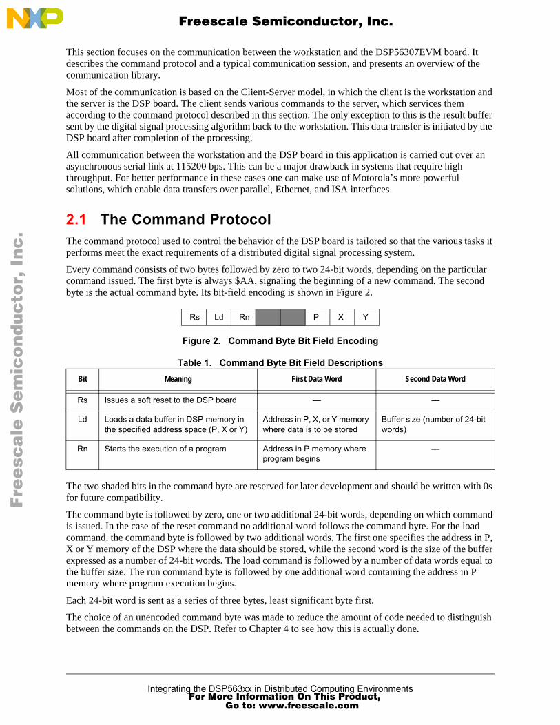
This section focuses on the communication between the workstation and the DSP56307EVM board. It describes the command protocol and a typical communication session, and presents an overview of the communication library.
Most of the communication is based on the Client-Server model, in which the client is the workstation and the server is the DSP board. The client sends various commands to the server, which services them according to the command protocol described in this section. The only exception to this is the result buffer sent by the digital signal processing algorithm back to the workstation. This data transfer is initiated by the DSP board after completion of the processing.
All communication between the workstation and the DSP board in this application is carried out over an asynchronous serial link at 115200 bps. This can be a major drawback in systems that require high throughput. For better performance in these cases one can make use of Motorola’s more powerful solutions, which enable data transfers over parallel, Ethernet, and ISA interfaces.
2.1 The Command ProtocolThe command protocol used to control the behavior of the DSP board is tailored so that the various tasks it performs meet the exact requirements of a distributed digital signal processing system.
Every command consists of two bytes followed by zero to two 24-bit words, depending on the particular command issued. The first byte is always $AA, signaling the beginning of a new command. The second byte is the actual command byte. Its bit-field encoding is shown in Figure 2.
Figure 2. Command Byte Bit Field Encoding
Table 1. Command Byte Bit Field Descriptions
The two shaded bits in the command byte are reserved for later development and should be written with 0s for future compatibility.
The command byte is followed by zero, one or two additional 24-bit words, depending on which command is issued. In the case of the reset command no additional word follows the command byte. For the load command, the command byte is followed by two additional words. The first one specifies the address in P, X or Y memory of the DSP where the data should be stored, while the second word is the size of the buffer expressed as a number of 24-bit words. The load command is followed by a number of data words equal to the buffer size. The run command byte is followed by one additional word containing the address in P memory where program execution begins.
Each 24-bit word is sent as a series of three bytes, least significant byte first.
The choice of an unencoded command byte was made to reduce the amount of code needed to distinguish between the commands on the DSP. Refer to Chapter 4 to see how this is actually done.
Bit Meaning First Data Word Second Data Word
Rs Issues a soft reset to the DSP board — —
Ld Loads a data buffer in DSP memory in the specified address space (P, X or Y)
Address in P, X, or Y memory where data is to be stored
Buffer size (number of 24-bit words)
Rn Starts the execution of a program Address in P memory where program begins
—
Rs Ld Rn P X Y
Fre
esc
ale
Se
mic
on
du
cto
r, I
Freescale Semiconductor, Inc.
For More Information On This Product, Go to: www.freescale.com
nc
...

Communication Library Functions Overview
Workstation-DSP Communication Protocol
Every command received by the DSP board is acknowledged by a command confirmation string. These strings are shown in Table 2
.
The command confirmation string for the load command is followed by a 24-bit checksum computed as a modulo 224 sum of all the data words in the buffer. The command confirmation string for the run command is followed by the address supplied in the run command.
A typical communication session between the workstation and the DSP board might proceed as follows:
1. The PC sends a Reset command to the DSP board: $AA, $80.
2. The DSP board answers by sending the command confirmation string #Ready after performing a soft reset.
3. The PC downloads all the input data buffers as well as the DSP algorithm to the DSP board. Each buffer is downloaded in the following sequence:
a) The PC issues a Load command:
– $AA, $44 for loading into P memory
– $AA, $42 for loading into X memory
– $AA, $41 for loading into Y memory
b) The PC sends two data words to the DSP board containing the starting address where the data is to be loaded and the number of words to be sent.
c) The PC sends the data words, which the DSP board loads into memory while computing a checksum.
4. The DSP board answers by sending the command confirmation string #Ld followed by the checksum of the loaded buffer.
5. The PC validates the checksum.
6. The PC sends a Run command: $AA, $20, and the start address of the program.
7. The DSP board acknowledges receiving the command by sending the string #Ok followed by the start address supplied in the Run command.
Control is then transferred to the processing program which is responsible for sending the result buffers back to the PC.
2.2 Communication Library Functions OverviewThe SCOM (Serial COMmunication) communication library is written in C and designed to run under Linux. It provides a set of low-level functions to perform the actual data transfer through the RS-232 serial port of the workstation as well as some high-level functions to implement the command protocol. It was designed to handle multiple DSP boards simultaneously, each identified by a special identifier called ‘serial device id’ (sdid).
Table 2. Command Confirmation Strings
Command String Subsequent Word
Reset #Ready —
Load #Ld Buffer checksum
Run #Ok Run address
Fre
esc
ale
Se
mic
on
du
cto
r, I
Freescale Semiconductor, Inc.
For More Information On This Product, Go to: www.freescale.com
nc
...

Integrating the DSP563xx in Distributed Computing Environments
All functions have a parameter sid of type (sdid *). The sdid structure is shown in Code Example 1:
Code Example 1. The sdid Structurestruct sdevid {
int fd;struct termios oldtio;
};typedef struct sdevid sdid;
fd - file descriptor associated with the serial device fileoldtio - structure holding the previous settings of the serial device
All functions return at least one error code. The error codes are listed in Table 3.
2.2.1 Low-Level FunctionsThe communications library includes a set of functions which perform the low-level operations associated with serial I/O.
2.2.1.1 scom_init— Initializes the serial port for:
• 8-bit mode
• 1 stop bit
• no parity
• communication speed of 115200 bps.
— Fills the sid structure with the appropriate device information— Programs the serial device for buffered I/O.— Sets a predefined time-out value for the receiver.
Table 3. SCOM Error Codes
Error code Description
ER_OK The operation was successful
ER_UNKNOWN Returned by scom_run when it does not receive the command confirmation string
ER_PARM At least one argument passed to a function is invalid
ER_TOUT A time-out occurred before reading a specified number of bytes
ER_IO Returned by scom_write_buf when it fails to send the entire buffer
ER_SUM Received checksum is not the same as the computed one
ER_STX Syntax error is encountered in the LOD file
ER_DSP Attempt to reset the DSP board fails
ER_EXT Returned in all other cases. ER_EXT is a macro; the actual value returned is (-_NO_OF_ERRS - errno)
Fre
esc
ale
Se
mic
on
du
cto
r, I
Freescale Semiconductor, Inc.
For More Information On This Product, Go to: www.freescale.com
nc
...

Communication Library Functions Overview
Workstation-DSP Communication Protocol
Code Example 2. The scom_init Function#include “scom.h”err_t scom_init(const char *device, sdid *sid);
device - serial device file name (/dev/ttySx)sid - serial device id
Error codes returned: ER_PARM, ER_EXT, ER_OK.
2.2.1.2 scom_shut_down— Flushes the input and the output buffers of the serial device— Closes the file descriptor associated with the serial device.
Code Example 3. The scom_shut_down Function#include “scom.h”err_t scom_shut_down(sdid *sid);
sid - serial device id
Error codes returned: ER_PARM, ER_EXT, ER_OK.
2.2.1.3 scom_write_buf— Outputs the contents of a data buffer to the specified serial device
Code Example 4. The scom_write_buf Function#include “scom.h”err_t scom_write_buf(sdid *sid, u_int8_t *buf, size_t count);
sid - serial device idbuf - buffer of unsigned bytescount - buffer size
Error codes returned: ER_IO, ER_EXT, ER_OK.
2.2.1.4 scom_read_buf— Performs buffered input from the serial device until either count bytes are read or a time-out occurs.
Code Example 5. The scom_read_buf Function#include “scom.h”err_t scom_read_buf(sdid *sid, u_int8_t *buf, size_t count);
sid - serial device idbuf - buffer of unsigned bytescount - buffer size
Error codes returned: ER_TOUT, ER_OK.
Fre
esc
ale
Se
mic
on
du
cto
r, I
Freescale Semiconductor, Inc.
For More Information On This Product, Go to: www.freescale.com
nc
...
Integrating the DSP563xx in Distributed Computing Environments
2.2.1.5 mdps_get_error— Returns the associated string to err_no error code.
Code Example 6. The mdsp_get_error Function#include “mdspcom.h”char *mdsp_get_error(err_t err_no);
err_no - error code
2.2.2 High-Level Functions
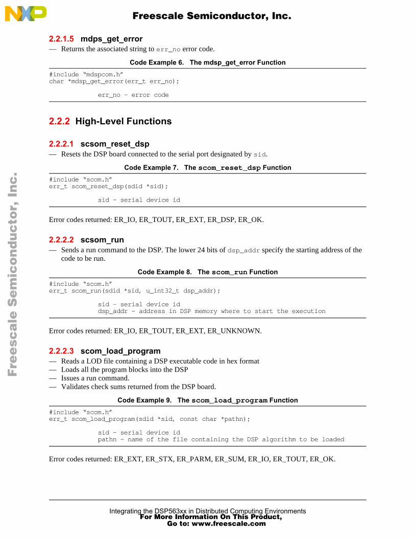
2.2.2.1 scsom_reset_dsp— Resets the DSP board connected to the serial port designated by sid.
Code Example 7. The scom_reset_dsp Function#include “scom.h”err_t scom_reset_dsp(sdid *sid);
sid - serial device id
Error codes returned: ER_IO, ER_TOUT, ER_EXT, ER_DSP, ER_OK.
2.2.2.2 scsom_run— Sends a run command to the DSP. The lower 24 bits of dsp_addr specify the starting address of the
code to be run.
Code Example 8. The scom_run Function#include “scom.h”err_t scom_run(sdid *sid, u_int32_t dsp_addr);
sid - serial device iddsp_addr - address in DSP memory where to start the execution
Error codes returned: ER_IO, ER_TOUT, ER_EXT, ER_UNKNOWN.
2.2.2.3 scom_load_program— Reads a LOD file containing a DSP executable code in hex format— Loads all the program blocks into the DSP— Issues a run command.— Validates check sums returned from the DSP board.
Code Example 9. The scom_load_program Function#include “scom.h”err_t scom_load_program(sdid *sid, const char *pathn);
sid - serial device idpathn - name of the file containing the DSP algorithm to be loaded
Error codes returned: ER_EXT, ER_STX, ER_PARM, ER_SUM, ER_IO, ER_TOUT, ER_OK.
Fre
esc
ale
Se
mic
on
du
cto
r, I
Freescale Semiconductor, Inc.
For More Information On This Product, Go to: www.freescale.com
nc
...

Communication Library Functions Overview
The DSP56307 in a Distributed Environment
2.2.2.4 scom_write_dsp— Downloads a buffer of 8-bit integers into DSP memory at the specified address in the P, X or Y
address space. count must be a multiple of three; each three-byte group is concatenated to form a 24-bit word in DSP memory. The first byte in the group is the least significant.
Code Example 10. The scom_write_dsp Function#include “scom.h”err_t scom_write_dsp(sdid *sid, u_int8_t *buf, u_int32_t dsp_addr, u_int32_t count, u_int8_t pm);
sid - serial device idbuf - buffer of unsigned bytes to load into the DSP memorydsp_addr - address where to load the buffercount - size of bufferpm - a flag specifying the address space (P, X or Y memory).
Should contain one of the following values: PMEM, XMEM or YMEM.
Error codes returned: ER_EXT, ER_PARM, ER_SUM, ER_IO, ER_TOUT, ER_OK.
2.2.2.5 Helper FunctionsThe following two functions are referred to as ‘helper functions’ because they perform data conversion and are used in conjunction with specific DSP algorithms. scom_write_data_dsp is used to load a buffer of 24-bit integers to the DSP data memory. It does so by ignoring the most significant 8 bits of every 32-bit integer. scom_read_data_dsp is used to read a buffer of 24-bit words from the DSP. It stores each word in a 32-bit signed integer, extending its sign bit to the 8 most significant bits of the 32-bit integer.
Code Example 11. The Helper Functions#include “scom.h”err_t scom_write_data_dsp(sdid *sid, int *buf, u_int32_t count, u_int8_t pm);err_t scom_read_data_dsp(sdid *sid, int *buf, u_int32_t count);
sid - serial device idbuf - buffer of 32-bit integers of datacount - size of bufferpm - a flag specifying the address space: XMEM or YMEM.
Error codes returned:scom_write_data_dsp: ER_EXT, ER_PARM, ER_SUM, ER_IO, ER_TOUT, ER_OK.scom_read_data_dsp: ER_TOUT, ER_OK.
3 The DSP56307 in a Distributed EnvironmentThis section focuses on the implementation of the code running on the DSP56307 Evaluation Module (DSP56307EVM) as the core of a distributed DSP system as described in Section 1. This code provides a monitor-like interface to provide processing autonomy to the DSP and to facilitate as much as possible its programming and command from higher-level user applications.
Fre
esc
ale
Se
mic
on
du
cto
r, I
Freescale Semiconductor, Inc.
For More Information On This Product, Go to: www.freescale.com
nc
...
Integrating the DSP563xx in Distributed Computing Environments
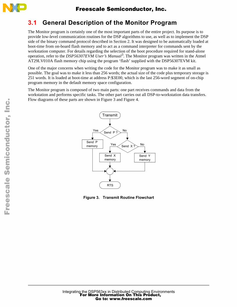
3.1 General Description of the Monitor ProgramThe Monitor program is certainly one of the most important parts of the entire project. Its purpose is to provide low-level communication routines for the DSP algorithms to use, as well as to implement the DSP side of the binary command protocol described in Section 2. It was designed to be automatically loaded at boot-time from on-board flash memory and to act as a command interpreter for commands sent by the workstation computer. For details regarding the selection of the boot procedure required for stand-alone operation, refer to the DSP56307EVM User’s Manual3. The Monitor program was written in the Atmel AT29LV010A flash memory chip using the program ‘flash’ supplied with the DSP56307EVM kit.
One of the major concerns when writing the code for the Monitor program was to make it as small as possible. The goal was to make it less than 256 words; the actual size of the code plus temporary storage is 251 words. It is loaded at boot-time at address P:$3E00, which is the last 256-word segment of on-chip program memory in the default memory space configuration.
The Monitor program is composed of two main parts: one part receives commands and data from the workstation and performs specific tasks. The other part carries out all DSP-to-workstation data transfers. Flow diagrams of these parts are shown in Figure 3 and Figure 4.
Figure 3. Transmit Routine Flowchart
YesSend P ?
No
Transmit
Send P memory Yes NoSend X ?
Send X memory
Send Y memory
RTS
Fre
esc
ale
Se
mic
on
du
cto
r, I
Freescale Semiconductor, Inc.
For More Information On This Product, Go to: www.freescale.com
nc
...

Monitor Program Implementation on DSP56307
The DSP56307 in a Distributed Environment
Figure 4. Receive Routine Flowchart
3.2 Monitor Program Implementation on DSP56307This section presents the source code for the Monitor program, including
• Symbolic constant definitions
• Initialization sequence
• Receive routine
• Load procedure
• Run Command procedure
• Transmit routine
Receive
Readcommand byte
Yes NoReset ?
Reset DSP
Jump bootstrap
ExitLoad P ?
Yes No
Read block sizeand address
Readprogram address
Set upreturn address
RTI
Load ?
Read block intoP memory Load X ?
Yes
Yes
No
No
Read block intoX memory
Read block intoY memory
Send checksum
RTI
Fre
esc
ale
Se
mic
on
du
cto
r, I
Freescale Semiconductor, Inc.
For More Information On This Product, Go to: www.freescale.com
nc
...

Integrating the DSP563xx in Distributed Computing Environments
3.2.1 DefinitionsThe first portion of the Monitor program defines the code defining symbolic constants for the memory-mapped registers. It also declares string constants, and reserves memory for data storage, both of which are used in the command confirmation strings. This code is listed in Code Example 12.
Code Example 12. Monitor Program—Equates and DefinesM_IPR_P equ $FFFFFEM_PCTL equ $FFFFFDM_PCRE equ $FFFF9FM_SCR equ $FFFF9CM_SCCR equ $FFFF9BM_SRxH equ $FFFF9AM_SRxM equ $FFFF99M_SRxL equ $FFFF98M_STxH equ $FFFF97M_STxM equ $FFFF96M_STxL equ $FFFF95M_SSR equ $FFFF93
ORG P:$3E00JMP Init
SReset DCB ’eR#yda’SRun DCB ’kO#’SRAdr DS 1SLoad DCB ’dL#’SLAdr DS 1R0Reg DS 1Regs DS 7LastReg DS 1
Fre
esc
ale
Se
mic
on
du
cto
r, I
Freescale Semiconductor, Inc.
For More Information On This Product, Go to: www.freescale.com
nc
...

Monitor Program Implementation on DSP56307
The DSP56307 in a Distributed Environment
3.2.2 InitializationAfter a soft reset, the main program begins with an initialization sequence, starting at the Init label. This sequence consists of the following steps:
1. The IPL in the SR register is set to 2 and the IPL of the SCI is set to 2 to ensure that the SCI Receive Data interrupt is not masked out.
2. The PLL is enabled with a factor of 8.4 (42/5) to yield a core frequency of 103.2192 MHz.
3. The SCI Receive Data interrupt handler is set by writing a “JSR Receive” at P:$50, which is the address of the interrupt vector for the SCI Receive Data interrupt.
4. The entry point for the Transmit routine is written at address P:$54, which is the address of the SCI Transmit Data interrupt vector. The SCI Transmit Data interrupt is not used, so it is disabled and its interrupt vector is used for storage.
5. The communication parameters are set to 10-bit asynchronous mode, Transmit Interrupt disabled, and Receive Interrupt enabled by writing $B02 to the memory-mapped SCI Control Register (x:$FFFF9C).
6. SCI baud rate is set to 115200 by setting the SCCR Clock Divider to 13, which actually means a divisor of 14.
After this set up is completed, the Monitor program sends the acknowledgement string “#Ready” to the workstation computer and the DSP goes into the WAIT state until a SCI receive interrupt occurs.
The initialization sequence is listed in Code Example 13.
Code Example 13. Monitor Program—Initialization SequenceInit
MOVEC #$C00200,SR ;Set IPL to 2MOVEP X:M_IPR_P,A1OR #$C0,AMOVEP A1,X:M_IPR_P ;Set SCI IPL to 2MOVEP #$460029,X:M_PCTL ;Set PLL factor to 8.4MOVE #$50,R0NOPMOVE #$0BF080,A1MOVEM A1,P:(R0)+
LRA Receive,A1MOVEM A1,P:(R0) ;Set up receive interrupt vectorMOVE #$54,R0LRA Transmit,A1MOVEM A1,P:(R0) ;Set transmit entry pointMOVEP #$0B02,X:M_SCR ;Set up SCI communication parametersMOVEP #13,X:M_SCCR ;Set SCI baud rateMOVEP #7,X:M_PCRE ;Enable Rx,Tx and SCLK pins for SCIMOVE #4,A2LRA SReset,R0MOVE #2,A0JSR Transmit
_LoopWAITJMP _Loop
Fre
esc
ale
Se
mic
on
du
cto
r, I
Freescale Semiconductor, Inc.
For More Information On This Product, Go to: www.freescale.com
nc
...

Integrating the DSP563xx in Distributed Computing Environments
3.2.3 Receive RoutineWhen the SCI receives a byte, it generates a SCI Receive Interrupt, which wakes the DSP from the WAIT state. Program execution resumes by servicing the pending interrupt. The Receive Data interrupt handling routine saves all the registers used by the routine and restores them upon exiting the routine.
After saving the registers to memory, the Monitor program reads the received byte from the lower 8 bits of the SCI Receive Data Register, memory mapped at address $X:FFFF98. If this byte is equal to $AA, a new command is being issued by the workstation and the Monitor program waits to read more bytes according to the protocol. If the received byte is not equal to $AA, the routine restores the saved registers and exits, and the DSP resumes the WAIT state. Once the $AA byte is received, the Receive Data Interrupt handling routine does not exit until the current command is fully processed.
The next received byte after the initial $AA is the command byte, illustrated in Figure 2 on page 4. Note that although the encoding scheme makes it possible to issue multiple commands in the same command byte, this is not permitted in the protocol. If more than one command bit is set, the command corresponding to the most significant bit set executed. For example, if the Reset bit is set, other command bits are ignored. If no command bit is set, the Run command is assumed.
Bits 0–2 of the command byte are ignored and for the Reset and the Run commands. For the Load command, these bits they are checked in the following order: P, X and Y; if none of these bits is set, Y is assumed. Refer to the receive routine flowchart in Figure 4 on page 11.
In response to the Reset command, the routine issues a soft reset by writing the default boot-time values to the SR, SC, SP and OMR registers and jumping to the bootstrap code at P:$FF0000. The default setting for the MD, MC, MB and MA bits in the COM register is assumed to be 1001b, meaning boot from byte-wide memory. The bootstrap code then reloads the Monitor program from the flash memory and runs the main program starting at Init label. This code sets up of the DSP board and sends the #Ready command confirmation string, indicating that the Reset was successful.
The receive routine is listed in Code Example 14.
Code Example 14. Monitor Program—Receive RoutineReceive
MOVEM R0,P:R0RegLRA Regs,R0MOVEM M0,P:(LastReg)MOVE #$FFFFFF,M0MOVEM R1,P:(R0)+MOVEM A2,P:(R0)+MOVEM A1,P:(R0)+MOVEM A0,P:(R0)+MOVEM B2,P:(R0)+MOVEM B1,P:(R0)+MOVEM B0,P:(R0) ;Save regsJCLR #2,X:M_SSR,*MOVEP X:M_SRxL,A1MOVE #0,A0MOVE #0,A2CMP #$AA,AJNE _EndJCLR #2,X:M_SSR,*MOVEP X:M_SRxL,A2 ;Read command byteNOPJCLR #7,A2,_LoadOrRunRESET ;DSP ResetMOVEC #0,SPMOVEC #0,SCMOVEC #$C00300,SRMOVEC #$000309,OMRJMP $FF0000 ;Jump to bootstrap
Fre
esc
ale
Se
mic
on
du
cto
r, I
Freescale Semiconductor, Inc.
For More Information On This Product, Go to: www.freescale.com
nc
...

Monitor Program Implementation on DSP56307
The DSP56307 in a Distributed Environment
3.2.4 Load ProcedureAs described in Section 2, the Load procedure downloads the number of 24-bit data words specified in the command protocol. This is accomplished by simply moving the received bytes to the B1 register and then right-shifting the B register. After completing a cycle of three moves and three shifts, B0 holds the resulting 24-bit word, which is moved to P, X or Y memory according to the command protocol. After each cycle, the content of the B register is added to the A register. At the end of the transfer, A0 holds the checksum of the received buffer, which is then sent back to the workstation where it is validated. The checksum is prefixed by the command confirmation string #Ld.
The Load procedure is listed in Code Example 15.
Code Example 15. Monitor Program—Load Procedure_LoadOrRun
JCLR #6,A2,_RunDO #6,_Loop1JCLR #2,X:M_SSR,*MOVEP X:M_SRxL,B2ASR #8,B,B
_Loop1 ;Read address and block sizeNOPMOVE B0,R0MOVE #0,A0MOVE B0,R1 ;Save start addressJCLR #2,A2,_LoadXYDO B1,_Loop2DO #3,_Loop21JCLR #2,X:M_SSR,*MOVEP X:M_SRxL,B1ASR #8,B,B
_Loop21NOPMOVEM B0,P:(R0)+ADD B,A
_Loop2 ;Read block into P memoryJMP _SendCRC
_LoadXYJCLR #1,A2,_LoadYDO B1,_Loop3DO #3,_Loop31JCLR #2,X:M_SSR,*MOVEP X:M_SRxL,B1ASR #8,B,B
_Loop31NOPMOVE B0,X:(R0)+ADD B,A
_Loop3 ;Read block into X memoryJMP _SendCRC
_LoadYDO B1,_Loop4DO #3,_Loop41JCLR #2,X:M_SSR,*MOVEP X:M_SRxL,B1ASR #8,B,B
_Loop41NOPMOVE B0,Y:(R0)+ADD B,A
_Loop4 ;Read block into Y memoryJMP _SendCRC
Fre
esc
ale
Se
mic
on
du
cto
r, I
Freescale Semiconductor, Inc.
For More Information On This Product, Go to: www.freescale.com
nc
...
Integrating the DSP563xx in Distributed Computing Environments
3.2.5 Run Command ProcedureThe Run Command procedure is implemented as follows.
1. The DSP receives the Run command, followed by the start address of the program to run.
2. The DSP sends back the command confirmation string “#Ok” followed by the received address.
3. The address is pushed onto the upper half of the stack (SSH).
4. A value of $C00200 is pushed to the lower half of the stack (SSL).
5. Execution continues until the end of the Receive routine, where a RTI instruction is issued.
The RTI instruction loads the PC register with the address at which execution is to resume from the SSH register, which contains the value sent by the Run command. The RTI also loads the SR from SSL, which contains the value $C00200. This sets the core priority level to 3 and the interrupt priority level to 2, which enables the Monitor program to continue to receive and execute commands, interrupting the running algorithm. This ability is very useful for interrupting a lengthy operation to perform a less time-consuming function.
The Run Command procedure is listed in Code Example 16.
Fre
esc
ale
Se
mic
on
du
cto
r, I
Freescale Semiconductor, Inc.
For More Information On This Product, Go to: www.freescale.com
nc
...

Monitor Program Implementation on DSP56307
The DSP56307 in a Distributed Environment
Code Example 16. Monitor Program—Run Command Procedure_Run
JCLR #5,A2,_EndDO #3,_Loop5JCLR #2,X:M_SSR,*MOVEP X:M_SRxL,A2ASR #8,A,A
_Loop5 ;Read addressNOPLRA SRAdr,R0MOVE A1,R1MOVE #4,A2MOVEM R1,P:(R0)-MOVE #2,A0JSR TransmitMOVEC R1,SSHMOVE #$C00200,A0MOVEC A0,SSL ;Set up return addressJMP _End
_SendCRCLRA SLAdr,R0MOVE #4,A2NOPMOVEM A0,P:(R0)-MOVE #2,A0JSR TransmitJMP _End
_EndLRA Regs,R0NOPNOPMOVEM P:(R0)+,R1MOVEM P:(R0)+,A2MOVEM P:(R0)+,A1MOVEM P:(R0)+,A0MOVEM P:(R0)+,B2MOVEM P:(R0)+,B1MOVEM P:(R0)+,B0MOVEM P:(R0),M0MOVEM P:R0Reg,R0 ;Restore regsRTI ;Return from interrupt
Fre
esc
ale
Se
mic
on
du
cto
r, I
Freescale Semiconductor, Inc.
For More Information On This Product, Go to: www.freescale.com
nc
...

Integrating the DSP563xx in Distributed Computing Environments
3.2.6 Transmit RoutineThe Monitor program also provides a low-level Transmit routine which DSP algorithms can use to send back results. Its use is simple and straightforward:
1. A memory address space code is written to A2 register:
— #4 for P memory
— #2 for X memory
— #1 for Y memory
2. The size of the buffer is written to the A0 register.
3. The starting address of the buffer is written to the R0 register.
4. A JSR is performed to the address stored at P:$54.
Again, if none of the memory spaces is specified, the 3 least significant bits of A2 are cleared, and Y memory space is assumed. Refer to the flowchart in Figure 3 on page 10.
The Transmit routine is listed in Code Example 17.
Fre
esc
ale
Se
mic
on
du
cto
r, I
Freescale Semiconductor, Inc.
For More Information On This Product, Go to: www.freescale.com
nc
...

Monitor Program Implementation on DSP56307
The DSP56307 in a Distributed Environment
Code Example 17. Monitor Program—Transmit Routine; Transmit: sends a buffer through the SCI to the host computer; A2 <- 4 - send buffer from P memory; A2 <- 2 - send buffer from X memory; A2 <- 1 - send buffer from Y memory; A0 <- number of 24 bit words to send; R0 <- start address of buffer
TransmitJCLR #2,A2,_SaveXYDO A0,_LoopT1JCLR #1,X:M_SSR,*MOVEP P:(R0),X:M_STxLJCLR #1,X:M_SSR,*MOVEP P:(R0),X:M_STxMJCLR #1,X:M_SSR,*MOVEP P:(R0)+,X:M_STxHNOP
_LoopT1 ;Save P memoryJMP _EndT
_SaveXYJCLR #1,A2,_SaveYDO A0,_LoopT2NOPNOPJCLR #1,X:M_SSR,*MOVEP X:(R0),X:M_STxLNOPNOPJCLR #1,X:M_SSR,*MOVEP X:(R0),X:M_STxMNOPNOPJCLR #1,X:M_SSR,*MOVEP X:(R0)+,X:M_STxHNOP
_LoopT2 ;Save X memoryJMP _EndT
_SaveYDO A0,_LoopT3NOPNOPJCLR #1,X:M_SSR,*MOVEP Y:(R0),X:M_STxLNOPNOPJCLR #1,X:M_SSR,*MOVEP Y:(R0),X:M_STxMNOPNOPJCLR #1,X:M_SSR,*MOVEP Y:(R0)+,X:M_STxHNOP
_LoopT3 ;Save Y memory
_EndTRTS ;Return from subroutine
Fre
esc
ale
Se
mic
on
du
cto
r, I
Freescale Semiconductor, Inc.
For More Information On This Product, Go to: www.freescale.com
nc
...

Integrating the DSP563xx in Distributed Computing Environments
4 Case StudyAs a case study, a distributed digital signal processing system was developed using two personal computers interconnected with a TCP/IP-based Ethernet, both running the KHOROS software package from Khoral Research, Incorporated, on the Linux platform. The core of the system is the DSP56307 Evaluation Module, which performs all the DSP-specific operations initiated by the remote station, which is the controlling computer.
This section describes the architecture of the case study system, lists two DSP algorithms to be run in the system, presents an overview of the KHOROS software, and shows how the KHOROS software is used to implement one of the DSP algorithms in the system.
4.1 General ArchitectureThe general architecture of the proposed system is similar to the distributed computing generic architecture presented in Section 1 and is illustrated in Figure 5.
Figure 5. Architecture of the Proposed System
The system has three main components: a controlling computer, a workstation, and a DSP56307 Evaluation Module.
4.1.1 Controlling ComputerThe controlling computer is a special kind of workstation that controls overall system operation. It’s functions include
• Assisting the user in implementing the desired DSP network
• Controlling the distribution of tasks among the various processors
• Gathering and presenting the final results.
The system requirements for the controlling computer include:
• The Linux operating system
• An Ethernet interface, running TCP/IP protocol
Fre
esc
ale
Se
mic
on
du
cto
r, I
Freescale Semiconductor, Inc.
For More Information On This Product, Go to: www.freescale.com
nc
...

General Architecture
Case Study
• The KHOROS package, installed and configured
• The Cantata component of the KHOROS package, installed and configured
• A custom-designed ‘glyph’ toolbox created in Cantata which implements and distributes the DSP algorithms to be run on the DSP-based board.
The Cantata application is a highly interactive graphic environment which uses a building block called a ‘glyph’ (see Section 4.3.2 on page 25). On the controlling computer, Cantata is used to build a ‘DSP Network’ to implement DSP algorithms. This network uses signal processing glyphs provided by the KHOROS standard distribution package as well as specialized glyphs which are custom-designed to run corresponding DSP algorithms on the DSP-based board. These specialized glyphs can be grouped in a custom toolbox which Cantata can use to build, run, and control the particular DSP algorithms needed in distributed applications.
NOTE:In this document, a ‘software object’ refers to a program that performs dataprocessing, while a ‘glyph’ is a graphical representation of a softwareobject in Cantata. For simplicity, these terms are used interchangeably.
A basic custom toolbox called ‘Freescale EVM’ was developed for this case study. It contains two demonstration glyphs—kmsum, a simple adder of two input signals, and kmfft, a simple 256-point FFT. The two glyphs can be used to run the corresponding algorithms directly on the system’s Freescale DSP board in a distributed manner, over the Ethernet.
When the DSP network on the controlling computer is launched under Cantata, it processes the corresponding data flow diagram. When a local glyph is activated, it launches the corresponding procedures on the controlling computer’s own processor. If the data flow on the DSP Network reaches one of the glyphs that implements a DSP algorithm on the Freescale EVM, the KHOROS system on the controlling computer sends an execution command along with input parameters and data to the corresponding workstation through the Ethernet and waits for the processing results to be returned from the DSP. The received results are further used by the implemented DSP network.
The fact that some algorithms in a specific DSP network are executed by other components of the overall system is transparent to the user.
4.1.2 WorkstationThe primary function of the workstation in the proposed distributed DSP system is to serve as a remote interface between the controlling computer’s DSP network implemented under the Cantata application and the DSP-based board, where the actual signal processing algorithms are executed in distributed manner.
The system requirements for the workstation include:
• The LINUX operating system
• An Ethernet interface for communicating with the controlling computer
• The KHOROS package, installed and configured, to interpret the specific commands and input data issued by the controlling computer under Cantata and received on the DSP network
• A custom-designed glyph toolbox for Cantata, implementing DSP algorithms to be run on the DSP-based board in distributed manner. This is the same toolbox implemented on the controlling computer
• A communication library implemented on the LINUX platform for direct interconnection with the corresponding DSP-based board.
Fre
esc
ale
Se
mic
on
du
cto
r, I
Freescale Semiconductor, Inc.
For More Information On This Product, Go to: www.freescale.com
nc
...

Integrating the DSP563xx in Distributed Computing Environments
The workstation communicates with the DSP-based board through its standard PC asynchronous serial interface, which can exchange data at rates up to 115200 bps. The primary reason for using this port is that it can connect to the SCI port on the Freescale EVM, as described in Section 1.2 on page 2. Serial program and data communication with the DSP is implemented on the host workstation as a library of C-callable functions on UNIX-like platforms.
When execution of the DSP network on the controlling computer reaches one of the ‘remote DSP glyphs’ it issues a specific command to the workstation, and the routine that implements the corresponding glyph is launched. The primary actions performed by this routine include the following:
• Receive additional input data, if any
• Load the input data and parameters into the DSP through the serial data link
• Load the object code for the specific DSP routine into the DSP
• Wait for the results from the DSP
• Send the results back to the controlling computer.
4.1.3 DSP-Based BoardThe Freescale DSP563xx Evaluation Modules (EVM) was selected as the DSP hardware core of the distributed system. It uses an on-board standard serial communication interface (SCI port) to communicate with the host workstation, using the Monitor program described in Section 3 on page 9.
The actual DSP routines to be run on the EVM resides on the host workstation in the ‘.lod’ loadable object code format. They are loaded into the DSP along with additional input data and parameters by the corresponding glyph routines on the host machine.
Fre
esc
ale
Se
mic
on
du
cto
r, I
Freescale Semiconductor, Inc.
For More Information On This Product, Go to: www.freescale.com
nc
...

DSP Algorithms
Case Study
4.2 DSP AlgorithmsEach of the two DSP algorithms in our case study, the adder and the FFT, starts with all input data already loaded into memory on the DSP board. Each algorithm processes the data and calls the Transmit routine in the Monitor program to send the results back to the workstation.
4.2.1 Adder AlgorithmThis algorithm starts with two data buffers in X and Y memory spaces starting at address 1. Address 0 in both X and Y memory hold its respective buffer size. The algorithm performs an in-place sum of the two signals, using the larger buffer as a destination.
Code Example 18. Adder Algorithm Source Code (kmsum.asm)org x:0
XLength ds 1
org y:0YLength ds 1
org P:$100
Startmove #1,R0move x:XLength,Amove y:YLength,Bcmp B,Ajgt _XSumdo A1,_Loop1move x:(R0),Amove y:(R0),Badd B,Amove A1,y:(R0)+
_Loop1move #1,A2move y:YLength,A0jmp _Send
_XSumdo B1,_Loop2move x:(R0),Amove y:(R0),Badd B,Amove A1,x:(R0)+
_Loop2move #2,A2move X:XLength,A0
_Sendmove #$54,R0move p:(R0),R1move #1,R0jsr (R1)rts
End
Fre
esc
ale
Se
mic
on
du
cto
r, I
Freescale Semiconductor, Inc.
For More Information On This Product, Go to: www.freescale.com
nc
...

Integrating the DSP563xx in Distributed Computing Environments
4.2.2 FFT AlgorithmThis algorithm calls the FFTR2CN macro (© Motorola, Inc.) to perform the actual FFT.
Code Example 19. FFT Algorithm Source Code (kmfft.asm)include ’sincos’include ’bitrev’include ’fftr2cn’
NoOfPoints equ 256AddrOfInput equ 1AddrOfCoefs equ 4096AddrOfOutput equ 1024
org x:0XLength ds 1
org y:0YLength ds 1
sincos NoOfPoints,AddrOfCoefs
org P:$100Start
fftr2cn NoOfPoints,AddrOfInput,AddrOfOutput,AddrOfCoefs_Send
move #$FFFFFF,M0move #$54,R0move p:(R0),R1move #AddrOfOutput,R0move #NoOfPoints,A0move #2,A2jsr (R1)move #AddrOfOutput,R0move #1,A2jsr (R1)rts
End
4.3 The KHOROS EnvironmentThe KHOROS software package from Khoral Research is an advanced and complete digital signal processing and scientific software integration and development environment, featuring advanced inter-process and distributed computing support. KHOROS originated as a research project at the University of New Mexico. The first release of the KHOROS system, KHOROS 1.0 Beta, was made available via anonymous FTP in October, 1990 [6].
The goal of the KHOROS software is to provide a complete application development environment that redefines the software engineering process to include all members of the project group, from the application end-user to the infrastructure programmer [6].
4.3.1 CantataThe primary component of KHOROS is its visual design and simulation tool, called Cantata, a data flow visual language integrated in a powerful visual programming environment. It is extremely useful for developing and testing DSP algorithms in a very intuitive manner. Cantata enables a user to visually design a graphical data flow structure called a ‘DSP network’, assign nodes of the DSP network to the various computers on the network, and simulate the network while taking care of the various synchronization issues involved. A screen capture of a DSP network is shown in Figure 6.
Fre
esc
ale
Se
mic
on
du
cto
r, I
Freescale Semiconductor, Inc.
For More Information On This Product, Go to: www.freescale.com
nc
...

The KHOROS Environment
Case Study
Figure 6. Example of a Cantata Screen Layout
4.3.2 The GlyphThe building block of the DSP network is the ‘glyph’. A glyph is a visual representation of a process which runs on either a local or remote machine and performs a specific task such as the generation of a signal, processing of a previously generated set of signals, visualization of signals, etc. These fundamental construction blocks can be linked together in various ways to form the desired DSP network.
A glyph can best be viewed as a ‘black-box’, with inputs, outputs, and other specific controls, as illustrated in Figure 7.
Figure 7. Glyph Layout and Components
Fre
esc
ale
Se
mic
on
du
cto
r, I
Freescale Semiconductor, Inc.
For More Information On This Product, Go to: www.freescale.com
nc
...

Integrating the DSP563xx in Distributed Computing Environments
There are three basic types of glyphs used in a typical DSP network:
• Input glyphs—input procedures and programs such as signal generators or data import nodes
• Data processing glyphs—procedures that implement a large variety of algorithms
• Output glyphs—used for visualization or storage of results.
4.3.3 ToolboxesThe various types of glyphs can be grouped together in a ‘toolbox’ to clarify the way in which they are organized. A toolbox can be regarded as a collections of related ‘software objects’ as they are referred to in KHOROS terminology. The purpose of a toolbox is to facilitate domain-specific work while simultaneously enabling cross-domain collaboration [6]. Users can define their own toolboxes containing their own software objects, in relation to or based on others if desired. There is a one-to-one correspondence between software objects in a toolbox and their graphical representations as glyphs.
4.3.4 Software ObjectsSoftware objects can be of several types, including the following:
• Kroutines—non-interactive programs which read their data from a standard input, process the data and write results to a standard output. Every aspect of their execution is determined before running the program, and once the execution has begun, users have no means of intervening. An example of a Kroutine could be a data processing glyph or an input glyph.
• XVroutines—interactive, graphical programs. Interaction with XVroutines is achieved by means of a standardized set of graphical user interface elements, provided by KHOROS. An example of a typical XVroutine is a visualization glyph.
• Libraries—collections of routines that can be called from within other software objects. These routines can be LKroutines, public functions and private functions [11]. Refer to the Advanced KHOROS Manuals for a more detailed description.
4.3.5 Development ToolsIn addition to designing and simulating custom DSP networks, KHOROS provides a set of very powerful software development tools which allows full access to the KHOROS core. Programmers can conveniently design and implement their own software objects or libraries, group them into custom toolboxes, or extend the existing ones.
Two of the most important development tools are ‘Craftsman’ and ‘Composer.’ Their purpose is to assist the programmer in every phase of the software development process by automating specific tasks. Another very important tool is the ‘Graphical User Interface Specification Editor’ or GUISE. This tool allows the programmer to visually design the user interface component of a software object.
4.3.6 Data StructureKHOROS uses a unified data structure model to implement all of its procedures, thus providing comprehensive support for a very large set of real-life applications. This model, called a ‘polymorphic data model,’ is based on the premise that data in DSP applications is generated either to model, or acquired from, real-world phenomena, and consequently is suitable for these purposes [9]. Polymorphic data is composed of five so-called ‘segments,’ including VALUE, LOCATION, TIME, MASK and MAP.
Fre
esc
ale
Se
mic
on
du
cto
r, I
Freescale Semiconductor, Inc.
For More Information On This Product, Go to: www.freescale.com
nc
...

Using the KHOROS Software
Case Study
The primary segment is the VALUE segment, in which the actual data is stored as a time-series of volumes in space [9]. The VALUE segment has five dimensions—three positional coordinates, a time coordinate, and an ‘element,’ which is the size (number of components) of one point in space-time, as illustrated in Figure 8. VALUE data can be given explicit positioning in space and time with the LOCATION and TIME segments.
Figure 8. Structure of the VALUE Segment
The MASK and MAP segments are provided for convenience. The MASK segment is used to mark the validity of each point of VALUE data. The MAP segment is provided as an extension to the VALUE data; VALUE data can be used to index into the MAP data [9].
4.4 Using the KHOROS SoftwareThis section illustrates how the KHOROS software is used to incorporate a DSP algorithm into a software object which KHOROS can use to implement the algorithm in a distributed processing network. The general steps involved in creating a KHOROS software object include the following:
• Create a new toolbox or open an existing one using the Craftsman tool.
• Create the new software object using the Composer tool.
• Design the user interface for the created software object, using either Ghostwriter for a command line interface or GUISE for a graphical interface.
The adder algorithm is used to illustrate the process of building the glyphs and toolboxes KHOROS uses to implement a distributed processing system.
4.4.1 Building a ToolboxBefore a glyph can be created in KHOROS, the user must first configure a toolbox in which it will reside. The Craftsman tool is used either to modify a predefined toolbox or to create a new toolbox. For the case study, a new toolbox called ‘MotorolaEVM’ was created to contain all the data processing glyphs that make use of the Freescale evaluation modules. The creation of a toolbox is quite straightforward and is described in the KHOROS manuals.
4.4.2 Adding a Glyph to a ToolboxAdding software objects to a toolbox is also straightforward thanks to Composer. This tool features a C code editor, plus predefined operators and data structures which can be used to create the software object. If the user wishes to write custom code to create the object, Composer can be configured to generate just a
Fre
esc
ale
Se
mic
on
du
cto
r, I
Freescale Semiconductor, Inc.
For More Information On This Product, Go to: www.freescale.com
nc
...
Integrating the DSP563xx in Distributed Computing Environments
‘skeleton’ C code file to which the user can add the C statements needed to completely define all the object functions. The code written by the user inside the skeleton file is placed between a corresponding pair of special tags.
In this case study, two glyphs were added to the MotorolaEVM toolbox, kmsum and kmfft. The following paragraphs describe implementing kmsum to illustrate the process.
4.4.2.1 Defining the Glyph TasksThe kmsum Kroutine must perform the following tasks:
• Open its two inputs and one output
• Initialize communication with the attached DSP evaluation board (local or remote)
• Send data from the two inputs to the X and Y data memory on the DSP board
• Download the adder software routine to the DSP board
• Run the adder software
• Receive the results from the DSP board
• Write these results to the output
• Close the inputs and output and perform any other required cleanup tasks.
4.4.2.2 Creating a Directory StructureThe KHOROS software automatically creates the directory structure it requires. In our case study, the following directories were created within the ~/freescale/objects/ directory:
• kroutine/—the directory in which all Kroutines (source code) of the current toolbox are stored
• kroutine/kmsum—the root of the Kroutine in this toolbox
• kroutine/kmsum/src—contains the actual source code of the software object
• kroutine/kmsum/uis—contains the User Interface Specification (UIS) of the software object
• kroutine/kmsum/helpkroutine/kmsum/manvtkroutine/kmsum/html—contain manual pages and help files for the software object
The skeleton files for all of these directories are automatically generated by Craftsman.
4.4.3 Defining the Glyph User InterfaceAfter a glyph has been added to a toolbox, a User Interface Specification (UIS) must be constructed. The UIS defines all the interaction between the user and the software object. For the kmsum software object, which is a non-interactive Kroutine, this interaction is limited to setting the command line parameters to the object code, inputs, output, and flags before the routine is run. For a command line type of interface, the Ghostwriter tool is used to create the UIS. If a graphical user interface is needed instead, the GUISE application assists in the GUI design. Both tools generate code inside the software object skeleton file that was created in Composer. User-written code in the skeleton file is enclosed in special comment fields called ‘tags’ to prevent it from being altered. The most commonly used tags are summarized in Table 4. The last three sets of tags are not required; they are used to clarify the organization of the user code.
Fre
esc
ale
Se
mic
on
du
cto
r, I
Freescale Semiconductor, Inc.
For More Information On This Product, Go to: www.freescale.com
nc
...

Using the KHOROS Software
Case Study
When a Kroutine is created in Composer, one input field and one output field are defined by default. The kmsum Kroutine requires one additional input and a communications port to which the evaluation module is connected (either locally or to a remote workstation). For the case study, these elements were added using the GUISE program and the GUI it generates.
When GUISE is started, two dialog boxes appear. One is the graphical user interface for the software object, which is called a ‘pane,’ and the other is a form on which to make changes to the pane. The form was used to add a second input for the second signal source as well as an additional ‘String Selection’ control with a default value of /dev/ttyS1’ (the second serial device on a standard PC). Figure 9 shows the pane for kmsum after these additions.
Figure 9. Final Pane for kmsum
The final source code of the adder glyph is listed in Code Example 20. Due to the length of the code, only the main C file, kmsum.c, is listed.
Table 4. User Code Tags in Skeleton File
Tags Denotes
/* -main_variable_list *//* -main_variable_list_end */
Program variables
/* -main_get_args_call *//* -main_get_args_call_end */
Call to a special function which initializes the UIS, the structure containing the input parameters / command line arguments of the program.
/* -main_before_lib_call *//* -main_before_lib_call_end */
Initialization code
/* -main_library_call *//* -main_library_call_end */
Code that performs actual processing
/* -main_after_lib_call *//* -main_after_lib_call_end */
Cleanup code
Fre
esc
ale
Se
mic
on
du
cto
r, I
Freescale Semiconductor, Inc.
For More Information On This Product, Go to: www.freescale.com
nc
...

Integrating the DSP563xx in Distributed Computing Environments
Code Example 20. Final Source Code of the Adder Glyph, kmsum.c/* * KHOROS: $Id$ */
#if !defined(__lint) && !defined(__CODECENTER__)static char rcsid[] = “KHOROS: $Id$”;#endif
/* >>>>>>>>>>>>>>>>>>>>>>>>>>>>> <<<<<<<<<<<<<<<<<<<<<<<<<< >>>> >>>> Main program for kmsum >>>> >>>> Private: >>>> main >>>> >>>> Static: >>>> Public: >>>> >>>>>>>>>>>>>>>>>>>>>>>>>>>>> <<<<<<<<<<<<<<<<<<<<<<<<<< */
#include “kmsum.h”
clui_info_struct *clui_info = NULL;
/*-----------------------------------------------------------|| Routine Name: main() - Output is the sum of two inputs|| Purpose: main program for kmsum|| Input:| char *clui_info->i1_file; {First Input data object}| int clui_info->i1_flag; {TRUE if -i1 specified}|| char *clui_info->i2_file; {Second Input data object}| int clui_info->i2_flag; {TRUE if -i2 specified}|| char *clui_info->o_file; {Resulting output data object}| int clui_info->o_flag; {TRUE if -o specified}|| char *clui_info->commport_string; {Communications Port for the EVM}| int clui_info->commport_flag; {TRUE if -commport specified}|| Output:| Returns:|| Written By: Adrian Trifu| Date: May 10, 2000| Modifications:|------------------------------------------------------------*/
int main( int argc, char **argv){
/* -main_variable_list */
char *lib = “kmsum”, *rtn = “main”; kobject inobj1 = NULL; /* The inputs and the output are represented by */ kobject inobj2 = NULL; /* kobjects - data structures identifying polymorphic */ kobject outobj = NULL; /* data sets (see Section 4.3, "The KHOROS */
/* Environment"). Every I/O operation on polymorphic *//* data is done on these objects. */
kaddr inbuf1 = NULL; /* The only reason for having two separate */ kaddr inbuf2 = NULL; /* input buffers is to make the source code */
/* easier to understand. */
u_int32_t w1, w2, h, d, t, e, max; /* Used in determining the input’s size. */ sdid did; /* Device ID for the communications library. */ err_t res; /* Return code. */ char *lodpathname = NULL;
/* -main_variable_list_end */
Fre
esc
ale
Se
mic
on
du
cto
r, I
Freescale Semiconductor, Inc.
For More Information On This Product, Go to: www.freescale.com
nc
...

Using the KHOROS Software
Case Study
KHOROS_init(argc, argv, “FREESCALE”, PRODUCT_RELEASE_DATE, PRODUCT_RELEASE_NAME, PRODUCT_RELEASE_VERSION, PRODUCT_RELEASE_MAJOR, PRODUCT_RELEASE_MINOR, “$FREESCALE/objects/kroutine/kmsum”);kexit_handler(kmsum_free_args, NULL);
/* -main_get_args_call */kclui_init(“FREESCALE”, “kmsum”, KGEN_KROUTINE, &clui_uis_spec,
kmsum_usage_additions, kmsum_get_args, kmsum_free_args);
/* -main_get_args_call_end */
/* -main_before_lib_call */ /* Open the input and output objects, using *//* kpds_open_input_object() and */ /* kpds_open_output_object(), which are part *//* of the KHOROS Polymorphic Data Services. *//* Note that error reporting is done via /* specialized methods because errors */ /* are most often reported graphically *//* inside Cantata, although they can also be */ /* reported to stderr when the kroutine is *//* run in command-line. */
if ((inobj1 = kpds_open_input_object(clui_info->i1_file)) == KOBJECT_INVALID) {kerror(lib, rtn, “Cannot open input object %s.\n”, clui_info->i1_file);kexit(KEXIT_FAILURE);
} if ((inobj2 = kpds_open_input_object(clui_info->i2_file)) == KOBJECT_INVALID) {
kerror(lib, rtn, “Cannot open input object %s.\n”, clui_info->i2_file);kexit(KEXIT_FAILURE);
} if ((outobj = kpds_open_output_object(clui_info->o_file)) == KOBJECT_INVALID) {
kerror(lib, rtn, “Cannot open output object %s.\n”, clui_info->o_file);kexit(KEXIT_FAILURE);
}
/* Set the input data type to integer. This is *//* only the type in which data is read, NOT the *//* type of the actual data. All type *//* conversions are made automatically by the *//* read/write functions. */
kpds_set_attribute(inobj1, KPDS_VALUE_DATA_TYPE, KINT); kpds_set_attribute(inobj2, KPDS_VALUE_DATA_TYPE, KINT);
/* To determine how much data must be processed */ /* (taking into account that the two inputs can/* have different lengths), the greater of */ /* the two sizes is taken as the size of the output. */
kpds_get_attribute(inobj1, KPDS_VALUE_SIZE, &w1, &h, &d, &t, &e);kpds_get_attribute(inobj2, KPDS_VALUE_SIZE, &w2, &h, &d, &t, &e);max = (w1 > w2)? w1 : w2;
/* Finally, create the value segment in the output *//* object and set its dimensions according to the *//* maximum value determined earlier. The input and */ /* output objects are now ready to be used. */
kpds_create_value(outobj);kpds_set_attribute(outobj, KPDS_VALUE_SIZE, max, 1, 1, 1, 1);kpds_set_attribute(outobj, KPDS_VALUE_DATA_TYPE, KINT);
/* Before moving on to the next pair of tags, the */ /* the serial communication must be initialized with */ /* the evaluation board. This is done with a call to */ /* scom_init(), part of the communications library which /* is described in Chapter 2. *//* For simplicity it is assumed that the size of the */ /* inputs does not exceed the size of the X and Y */ /* memories. Otherwise, the data would have to be*/ /* tested and eventually sent in “slices”. However, */ /* this is not relevant, to our discussion. */
res = scom_init(clui_info->commport_string, &did);if (res != ER_OK) {
kerror(lib, rtn, “Error in scom_init(). Invalid tty specified.\n”);kexit(KEXIT_FAILURE);
}
/* -main_before_lib_call_end */
Fre
esc
ale
Se
mic
on
du
cto
r, I
Freescale Semiconductor, Inc.
For More Information On This Product, Go to: www.freescale.com
nc
...

Integrating the DSP563xx in Distributed Computing Environments
/* -main_library_call *//* Read the input data into the two defined buffers. */
if ((inbuf1 = kpds_get_data(inobj1, KPDS_VALUE_ALL, NULL)) == NULL) {kerror(lib, rtn, “Error reading input object %s\n”, clui_info->i1_file);kexit(KEXIT_FAILURE);
}if ((inbuf2 = kpds_get_data(inobj2, KPDS_VALUE_ALL, NULL)) == NULL) {
kerror(lib, rtn, “Error reading input object %s\n”, clui_info->i2_file);kexit(KEXIT_FAILURE);
}
/* Send the data from the input buffers to the *//* the DSP X: and Y: memory spaces respectively. */
res = scom_write_data_dsp(&did, (int *)inbuf1, (u_int32_t)w1, XMEM);if (res != ER_OK) {
kerror(lib, rtn, “Error %d writing X memory: %s\n”, res, mdsp_get_error(res));kexit(KEXIT_FAILURE);
}
res = scom_write_data_dsp(&did, (int *)inbuf2, (u_int32_t)w2, YMEM);if (res != ER_OK) {
kerror(lib, rtn, “Error %d writing Y memory: %s\n”, res, mdsp_get_error(res));kexit(KEXIT_FAILURE);
}
/* Load the object code of the actual DSP routine to be *//* currently executed on the DSP56307. *//* For simplicity, the code to synchronize the *//* execution on the DSP side with the execution */ /* on the PC side has been omitted. In this simple *//* case the sync code is not even necessary since *//* the time-out value in the read_data_dsp() function *//* is much larger than the amount of time taken to do *//* the actual calculations on the DSP. */
lodpathname = kfullpath(“kmsum.lod”, “$MOTOROLABIN”, NULL);res = scom_load_program(&did, lodpathname);if (res != ER_OK) {
kerror(lib, rtn, “Error %d loading program: %s\n”, res, mdsp_get_error(res));kexit(KEXIT_FAILURE);
}
/* Receive the resulting signal from the DSP and write *//* it into the output object, using kpds_put_data(), *//* part of the KHOROS Polymorphic Data Services. */
res = scom_read_data_dsp(&did, (int *)inbuf1, max);if (res != ER_OK) {
kerror(lib, rtn, “Error %d reading from DSP: %s\n”, res, mdsp_get_error(res));kexit(KEXIT_FAILURE);
}
if (kpds_put_data(outobj, KPDS_VALUE_ALL, (kaddr)inbuf1) == FALSE) {kerror(lib, rtn, “Error writing to output object %s\n”, clui_info->o_file);kexit(KEXIT_FAILURE);
}
/* -main_library_call_end */
/* -main_after_lib_call *//* Finally, close all the open kobjects, shut down */ /* communications and do other cleanup tasks. */
scom_shut_down(&did);
if (!kpds_set_attribute(outobj, KPDS_HISTORY, kpds_history_string())) {kerror(lib,rtn,”Unable to set history on destination object”);kexit(KEXIT_FAILURE);
}
kpds_close_object(inobj1); kpds_close_object(inobj2);
kpds_close_object(outobj);if (lodpathname) kfree_and_NULL(lodpathname);
/* -main_after_lib_call_end *//* Execution of the glyph ends here and data is *//* available to the next node in the dataflow chain. */
kexit(KEXIT_SUCCESS);
Fre
esc
ale
Se
mic
on
du
cto
r, I
Freescale Semiconductor, Inc.
For More Information On This Product, Go to: www.freescale.com
nc
...

Using the KHOROS Software
Case Study
}/* Additional routines needed by the "kmsum" glyph: */
/*-----------------------------------------------------------| | Routine Name: kmsum_usage_additions| | Purpose: Prints usage additions in kmsum_usage routine| | Input: None| | Output: None| Written By: ghostwriter -oname kmsum| Date: July 1, 1997| Modifications: | ------------------------------------------------------------*/void kmsum_usage_additions(void){
kfprintf(kstderr, “\tOutput is the sum of two inputs\n”);
/* -usage_additions *//* -usage_additions_end */
}
/*-----------------------------------------------------------| | Routine Name: kmsum_free_args| | Purpose: Frees CLUI struct allocated in kmsum_get_args()| | Input: None| | Output: None| Written By: ghostwriter -oname kmsum| Date: July 1, 1997| Modifications: | ------------------------------------------------------------*//* ARGSUSED */voidkmsum_free_args( kexit_status status, kaddr client_data){
/* do the wild and free thing */if (clui_info != NULL){
kfree_and_NULL(clui_info->i1_file);kfree_and_NULL(clui_info->i2_file);kfree_and_NULL(clui_info->o_file);kfree_and_NULL(clui_info->commport_string);kfree_and_NULL(clui_info);
}
/* -free_handler_additions *//* -free_handler_additions_end */}
This simple source code can be regarded as a general skeleton of any software object that uses Freescale EVMs to process data. The basic steps to be taken are exactly the same, no matter how complex the software object is. For example, a Freescale EVM-based data acquisition glyph can be added which brings real-world signals to KHOROS for further analysis and processing.
Fre
esc
ale
Se
mic
on
du
cto
r, I
Freescale Semiconductor, Inc.
For More Information On This Product, Go to: www.freescale.com
nc
...

Integrating the DSP563xx in Distributed Computing Environments
5 ConclusionThis paper provides a general framework for integrating Freescale DSP563xx-based boards in distributed digital data acquisition and processing systems, with special focus on the data communication between the DSP-based board and the host workstation.
A specific communication protocol was developed using the asynchronous serial interface, able to transact data up to 115200 bps. To improve the autonomy of the Freescale DSP563xx-based boards, a special Monitor program was developed to transfer programs and data between the DSP and the workstation through the serial communication interface (SCI), as well as the corresponding communication library for the workstation.
A case study distributed digital signal processing system was designed using two personal computers, one as a controlling computer and one as a workstation. The computers were connected by a TCP/IP-based Ethernet. Both computers used the KHOROS Software Package from Khoral Research, Incorporated, running on the Linux platform. All DSP-specific operations were initiated on the controlling computer and run on a DSP56307 Evaluation Module attached to the workstation through the SCI.
A custom toolbox called ‘Freescale EVM’ was created containing two specific DSP routines (‘Glyphs’)— kmsum, for adding two input signals, and kmfft, a 256-point Fast Fourier Transform, both running on Freescale DSPs in a distributed manner. The kmsum glyph was used illustrate the use of the KHOROS software.
The principles developed here can be applied to any DSP-based application that can be implemented in a distributed manner, such as digital signal acquisition and processing from sources scattered over large areas, and integrating multiple measurement and instrumentation units into a larger digital signal analysis structure.
Fre
esc
ale
Se
mic
on
du
cto
r, I
Freescale Semiconductor, Inc.
For More Information On This Product, Go to: www.freescale.com
nc
...

Using the KHOROS Software
References
6 References [1] DSP56300 Family User’s Manual, Motorola, Incorporated, 1999.
[2] DSP56307 24-Bit Digital Signal Processor User’s Manual, Motorola, Incorporated, 1999.
[3] DSP56307EVM User’s Manual, Motorola, Incorporated, 1999.
[4] Freescale DSP Assembler Reference Manual, Motorola Incorporated, 1999.
[5] Digital Signal Processing. Principles, Algorithms and Applications, A J. G. Proakis and D. G. Manolakis, 3rd edition, Prentice-Hall, 1996.
[6] Introduction to the KHOROS System, Khoral Research, Incorporated, Advanced Khoros Manuals, 1997.
[7] Toolbox Programming Manual, Khoral Research, Incorporated, Advanced Khoros Manuals, 1997.
[8] Programming Services I: Foundation Services, Khoral Research, Incorporated, Advanced Khoros Manuals, 1997.
[9] Programming Services II: Data Services, Khoral Research, Incorporated, Advanced Khoros Man-uals, 1997.
[10] Programming Services III: GUI and Visualization, Khoral Research, Incorporated, Advanced Khoros Manuals, 1997.
[11] Khoros Programming Tutorial, Rafael Santos, Internet Resources, 1997.
About the AuthorsMihai V. Micea is a lecturer at the Computer Software and Engineering Department at the Politehnica University of Timisoara, and Executive Director of the DSP Applications Lab Timisoara (DALT) sponsored by Digital DNA from Freescale.
Adrian TRIFU and Mircea TRIFU are students at the Automation and Computer Science Faculty at the POLITEHNICA University of Timisoara, and members of the research and development team at DALT.
Contacts:
• http://dsplabs.utt.ro/dalt/
Fre
esc
ale
Se
mic
on
du
cto
r, I
Freescale Semiconductor, Inc.
For More Information On This Product, Go to: www.freescale.com
nc
...

Integrating the DSP563xx in Distributed Computing Environments
Fre
esc
ale
Se
mic
on
du
cto
r, I
Freescale Semiconductor, Inc.
For More Information On This Product, Go to: www.freescale.com
nc
...