Embed Size (px)
Citation preview
NASA/TM-2003-212028
Integration of Online Parameter Identification and Neural Network for In-Flight Adaptive Control
Jacob J. Hageman, Mark S. Smith, and Susan StachowiakNASA Dryden Flight Research CenterEdwards, California
October 2003

The NASA STI Program Office…in Profile
Since its founding, NASA has been dedicatedto the advancement of aeronautics and space science. The NASA Scientific and Technical Information (STI) Program Office plays a keypart in helping NASA maintain thisimportant role.
The NASA STI Program Office is operated byLangley Research Center, the lead center forNASA’s scientific and technical information.The NASA STI Program Office provides access to the NASA STI Database, the largest collectionof aeronautical and space science STI in theworld. The Program Office is also NASA’s institutional mechanism for disseminating theresults of its research and development activities. These results are published by NASA in theNASA STI Report Series, which includes the following report types:
• TECHNICAL PUBLICATION. Reports of completed research or a major significantphase of research that present the results of NASA programs and include extensive dataor theoretical analysis. Includes compilations of significant scientific and technical data and information deemed to be of continuing reference value. NASA’s counterpart of peer-reviewed formal professional papers but has less stringent limitations on manuscriptlength and extent of graphic presentations.
• TECHNICAL MEMORANDUM. Scientificand technical findings that are preliminary orof specialized interest, e.g., quick releasereports, working papers, and bibliographiesthat contain minimal annotation. Does notcontain extensive analysis.
• CONTRACTOR REPORT. Scientific and technical findings by NASA-sponsored contractors and grantees.
• CONFERENCE PUBLICATION. Collected papers from scientific andtechnical conferences, symposia, seminars,or other meetings sponsored or cosponsoredby NASA.
• SPECIAL PUBLICATION. Scientific,technical, or historical information fromNASA programs, projects, and mission,often concerned with subjects havingsubstantial public interest.
• TECHNICAL TRANSLATION. English- language translations of foreign scientific and technical material pertinent toNASA’s mission.
Specialized services that complement the STIProgram Office’s diverse offerings include creating custom thesauri, building customizeddatabases, organizing and publishing researchresults…even providing videos.
For more information about the NASA STIProgram Office, see the following:
• Access the NASA STI Program Home Pageat
http://www.sti.nasa.gov
• E-mail your question via the Internet to [email protected]
• Fax your question to the NASA Access HelpDesk at (301) 621-0134
• Telephone the NASA Access Help Desk at(301) 621-0390
• Write to:NASA Access Help DeskNASA Center for AeroSpace Information7121 Standard DriveHanover, MD 21076-1320

NASA/TM-2003-212028
Integration of Online Parameter Identification and Neural Network for In-Flight Adaptive Control
Jacob J. Hageman, Mark S. Smith, and Susan StachowiakNASA Dryden Flight Research CenterEdwards, California
October 2003
National Aeronautics andSpace Administration
Dryden Flight Research CenterEdwards, California 93523-0273

NOTICE
Use of trade names or names of manufacturers in this document does not constitute an official endorsementof such products or manufacturers, either expressed or implied, by the National Aeronautics andSpace Administration.
Available from the following:
NASA Center for AeroSpace Information (CASI) National Technical Information Service (NTIS)7121 Standard Drive 5285 Port Royal RoadHanover, MD 21076-1320 Springfield, VA 22161-2171(301) 621-0390 (703) 487-4650

ABSTRACT
An indirect adaptive system has been constructed for robust control of an aircraft with uncertainaerodynamic characteristics. This system consists of a multilayer perceptron pre-trained neural network,online stability and control derivative identification, a dynamic cell structure online learning neuralnetwork, and a model following control system based on the stochastic optimal feedforward and feedbacktechnique. The pre-trained neural network and model following control system have been flight-tested,but the online parameter identification and online learning neural network are new additions used forin-flight adaptation of the control system model. A description of the modification and integration ofthese two stand-alone software packages into the complete system in preparation for initial flight tests ispresented. Open-loop results using both simulation and flight data, as well as closed-loop performance ofthe complete system in a nonlinear, six-degree-of-freedom, flight validated simulation, are analyzed.Results show that this online learning system, in contrast to the nonlearning system, has the ability toadapt to changes in aerodynamic characteristics in a real-time, closed-loop, piloted simulation, resultingin improved flying qualities.
NOMENCLATURE
coefficient of pitching moment due to angle of attack
DCS dynamic cell structure neural network
IFCS Intelligent Flight Control System
PID real-time parameter identification
PTNN pre-trained neural network
SOFFT stochastic optimal feedforward and feedback technique
INTRODUCTION
Advances in computational power and aircraft parameter estimation techniques have introduced theopportunity for real-time online estimation of aerodynamic stability and control derivatives for use inadaptive control. The Intelligent Flight Control System (IFCS) project,
1,2,3
combining the efforts ofNASA, academia, and industry, has proposed a set of control systems, estimation algorithms, and neuralnetworks for flight-testing in an effort to show real-time adaptation, allowing for safe, predictable controlof an aircraft with uncertain aerodynamic stability and control derivatives.
The software suite currently being tested is comprised of a pre-trained neural network
4
(PTNN) forcalculating the baseline aerodynamic stability and control derivatives, and real-time parameteridentification
5,6
(PID) paired with a dynamic cell structure neural network
7,8
(DCS). These routinesprovide near real-time estimates of the current aircraft derivatives to the research flight control system.The control system is based on the stochastic optimal feedforward and feedback technique
9,10
(SOFFT).The complete system is categorized as an indirect adaptive system, because adaptation modifies theaircraft plant model residing in the SOFFT controller, where a direct adaptive system uses feedbacksignals to generate command augmentation signals. The SOFFT controller was flight-tested in 1999
Cmα
2
using only the baseline derivatives from the PTNN. The PID and DCS software packages are newadditions to this system.
This report describes the progression of the stand-alone PID and DCS algorithms into a completesystem, including preflight integration and testing with extensive simulation use, and final preparation foropen-loop in-flight testing. The history of required modifications and enhancements for the PID and DCSare summarized, in addition to intermediate results and background discussions regarding the tradeoffsand configuration choices. Open-loop results using both simulation and flight data and closed-loopperformance of the complete system in a nonlinear, six-degree-of-freedom simulation are presented.
BACKGROUND
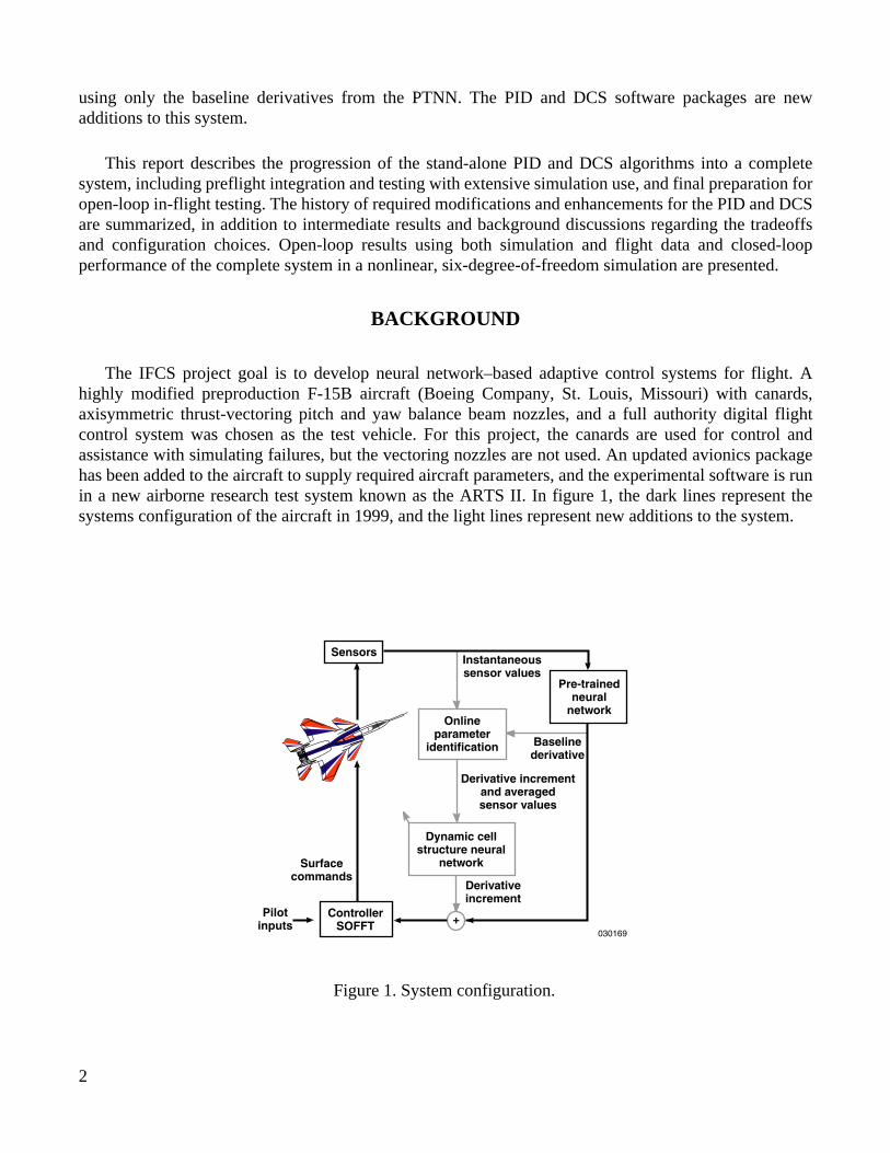
The IFCS project goal is to develop neural network–based adaptive control systems for flight. Ahighly modified preproduction F-15B aircraft (Boeing Company, St. Louis, Missouri) with canards,axisymmetric thrust-vectoring pitch and yaw balance beam nozzles, and a full authority digital flightcontrol system was chosen as the test vehicle. For this project, the canards are used for control andassistance with simulating failures, but the vectoring nozzles are not used. An updated avionics packagehas been added to the aircraft to supply required aircraft parameters, and the experimental software is runin a new airborne research test system known as the ARTS II. In figure 1, the dark lines represent thesystems configuration of the aircraft in 1999, and the light lines represent new additions to the system.
Sensors
Pre-trainedneural
network
Baselinederivative
Instantaneoussensor values
Derivativeincrement
Derivative incrementand averagedsensor values
Onlineparameter
identification
Pilotinputs +Controller
SOFFT
Surfacecommands
030169
Dynamic cellstructure neural
network
Figure 1. System configuration.
3
In the system shown in figure 1, the PTNN provides the wind-tunnel derived prediction of 26 stabilityand control derivatives based on flight condition and surface positions. Training is performed on theground before flight, and the algorithm has no online learning capability. The PTNN is classified as amultilayer perceptron (MLP) neural network. The training method uses a trust region variation of theLevenberg-Marquardt algorithm to optimize the network weights for a minimum mean square error. Thismethod has been used at the NASA Ames Research Center (Moffett Field, California) for prediction ofaircraft coefficients during wind-tunnel operations.
1
The SOFFT controller uses 26 stability and control derivatives with the aircraft states and pilot inputsto calculate surface commands. The main feature of the SOFFT control design methodology is theseparation of the feedforward and feedback portions of the controller to allow fast and smooth trackingresponse while suppressing noise and disturbances through the use of two different cost functions.
9,10
The feedforward part of the SOFFT controller uses a pilot selectable command model for achievingspecific handling characteristics (that is, frequency and damping). The feedback portion uses an onlineRiccati solver for stabilization and disturbance rejection. Both the feedforward and feedback portions ofthe controller rely on aircraft plant models formulated from aerodynamic stability and control derivatives.The ability to modify the aircraft plant model in flight in near real time using updated aerodynamicstability and control derivatives enables this controller to indirectly adapt to uncertain aerodynamics.
6
For the 1999 flights, to show the validity of using neural networks in flight, the PTNN derivativeswere fed into the SOFFT controller to update the aircraft plant model depending on flight conditions. Atthis stage no online learning of the neural network existed; the system would only recall estimates of thederivatives from the wind-tunnel data on which the PTNN had been trained. This system performed verywell in the lateral axis where the commanded roll rate and actual roll rate very closely matched. Incomparing the conventional control system to the PTNN and SOFFT controller, pilots commented thatthe new controller had similar or slightly improved handling qualities characteristics.
11,12
Pilots noteddegraded handling qualities in the pitch axis and commented that the commands did not track actual ratesas well as they did in the lateral axis. The suspected cause of this degradation is a difference between theoriginal wind-tunnel model estimate of , based on a previous rectangular engine nozzle design usedto train the PTNN, and the current configuration of the aircraft that uses round engine nozzles.
During the phase of flights completed in the spring of 2003, data were gathered for offline testing ofthe parameter estimation and learning neural network. In the next phase of flights, the aerodynamicstability and control derivatives will be estimated online in real time. The differences between the onlineestimates and the PTNN estimates will be stored as a function of flight condition with another neuralnetwork. This online learning portion of the system will be run open loop on the aircraft, allowing for aninitial comparison of the derivatives with the PTNN and postflight analysis routines before closing theloop. In the subsequent flight phase, the online estimates will be used to update the aircraft plant model inthe SOFFT controller, thereby closing the loop. At this stage, the ability of the entire system to activelyadapt to changing aerodynamic stability and control derivatives can be tested and analyzed.
Identification of the in-flight aircraft stability and control parameters is accomplished using PID,which involves correlating aircraft responses to control surface inputs. Various techniques have beenused postflight to calculate the aerodynamic stability and control derivatives, but the IFCS conceptrequires near real-time parameter identification during flight. The PID technique used for this study is areal-time equation error method that operates in the frequency domain called Fourier transform
Cmα
4
regression (FTR).
5
Modifications were made to the original technique for use in this study, including areduction in the number of calculated derivatives and operation on a time-based window of data.
6
A few properties of the PID algorithm must be considered. First, the PID has no long-term storage ofestimated derivatives, because it works only on a window of recent data. Another result of working on awindow of recent data is that estimated derivatives are not valid for the current flight condition. Instead,the estimates are correlated to averaged flight conditions over the data window. Also, the PID is only ableto compute valid estimates with sufficient system excitation, so the estimates should not be used undercertain conditions. For long-term storage and to fill in the gaps where PID results are not valid, the DCShas been added to the system to learn the estimated derivative corrections and recall instantaneous valuesfor use in the SOFFT controller.
The DCS belongs to the class of topology representing networks with mixed unit insertionsdepending on approximation error and stimulus distance. A competitive, nonsymmetric Hebbian rule isused for topology learning, and an error-modulated Kohonen rule is used for center adaptation, in whichthe goal is a uniform distribution of resource values.
7
The DCS has been used in a direct adaptive aircraftcontrol method with favorable piloted simulation results.
8
The simulation data shown in this report come from a six-degree-of-freedom, flight validated,nonlinear simulation using modified second-order Runge-Kutta integration.
13
Oblate Earth equations areused with a gravity model based on the Goddard Earth Model-10 and a standard day atmospheric model.Fixed-base, real-time, piloted flight and batch operation modes are available, and both are used forvalidation and verification of the research systems.
REAL-TIME PARAMETER IDENTIFICATION (PID)
A major goal for using PID in a real-time flight environment is to be able to calculate aerodynamicderivative information using typical pilot inputs and still obtain rapid convergence. As a result of usingpilot inputs, enough system excitation might not always exist to calculate accurate answers, or calculatederrors might be large, thus a measure of confidence in the derivatives is needed. Furthermore, thederivatives must be updated with respect to flight condition and aircraft configuration changes.
Postflight parameter identification methods can be used to calculate the same 26 aerodynamicstability and control derivatives estimated by the PTNN using independent stacked sine inputs to thesurfaces to decouple the dynamic effects.
14
Canards are symmetrically scheduled with angle of attack,and multiple surfaces are used for roll and yaw commands. These surface correlations cause difficulty incalculating independent surface contributions. To account for this difficulty, the number of derivativesestimated by the online PID was reduced to 13, and the other 13 derivatives are assumed known from thePTNN. This assumption creates an undesirable dependence on the PTNN for the individual derivativeresults, but because the focus is on the complete model using coordinated commands, the final result isacceptable.
The postflight version of the PID also works on the complete time history of data given to the system.To estimate derivatives for a specific flight condition, only that section of data would be given to the PID.Single averaged derivatives for that section of data would be output, whereas for the real-time system,derivatives must be updated as the flight condition changes. To perform the real-time updates, anadjustable data buffer stores the recent input information for the PID calculations. The lower size limit of

5
this buffer is driven by the amount of information needed for the PID to converge. The upper limit affectsthe response time of the PID and the ability of the PID to converge because of changing conditions. Forall results presented in this report, a 10-second data buffer is used. Because the derivatives are actually anaverage over the data in the buffer, the PID also averages the flight conditions to use as independentinputs for DCS training. Because the PID is always running while the research system is active on theaircraft, the inputs are tested and limited to avoid numerical errors in the matrix inversion routines of thealgorithm.
To determine the validity of the PID estimates for the current conditions, four types of tests areperformed. The first two tests measure the standard and relative error calculated for each derivative. Thethird test checks for a sufficient amount of system excitation per axis. The fourth and final test requiresthat the system pass the standard error test for a specific number of frames before a derivative isconsidered valid for DCS training.
5
For the flight test, many parameters that control the various functions of the PID are read from aconfiguration file, allowing for tuning of the algorithm between flights without requiring softwarerecompilation. Data buffer size, validity test limits, filter, and calibration values are variables included inthe configuration file.
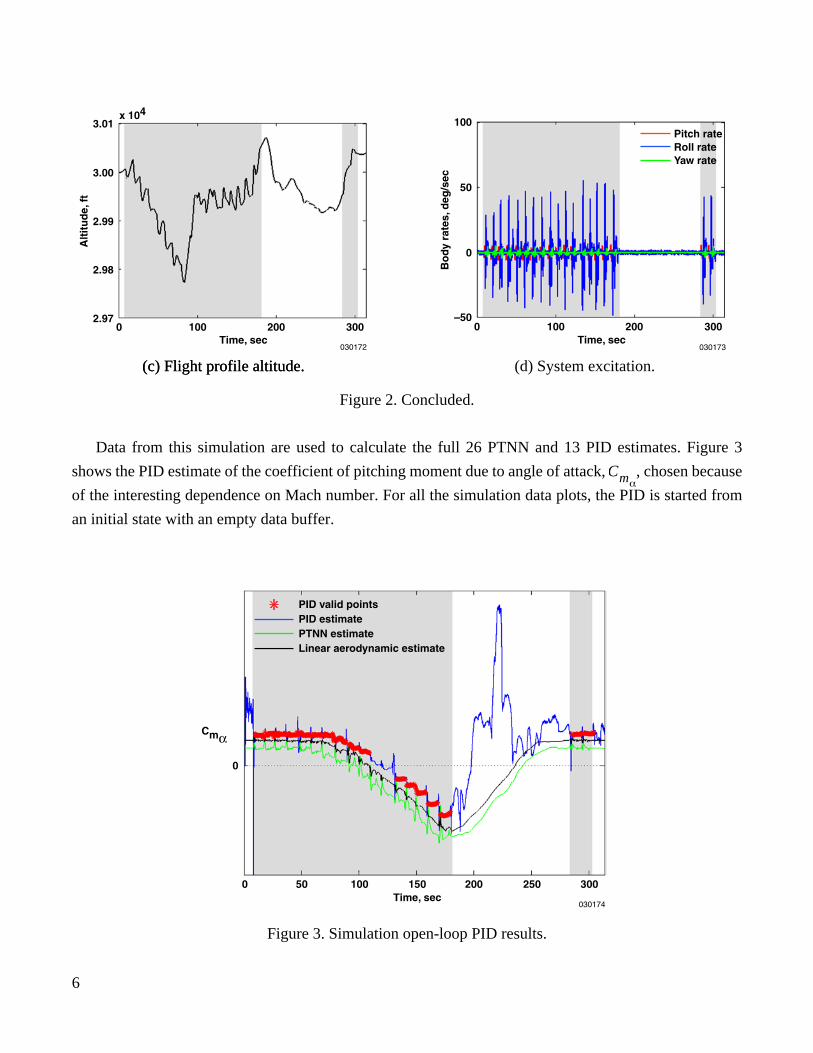
Figure 2 shows the F-15 IFCS piloted simulation flight profile used for open-loop PID testing. Theflight consisted of an acceleration with pitch, roll, and yaw doublets approximately every 7 secondsfollowed by a smooth deceleration and three doublets at the end, all at a constant altitude. The Machnumber ranged from 0.8 to 1.2, spanning the experimental envelope with the acceleration occurring in thefirst 175 seconds, followed by a deceleration back to initial conditions. For the plots presented here,highlighted portions of the profile indicate when the system was being excited by pilot inputs.
Alt
itu
de,
ft
4.0x 10⁴
.50
030170
.75 1.00Mach number
1.25 1.50
3.5
3.0
2.5
2.0
1.5
1.0
(a) Flight profile in experimental envelope. (b) Flight profile Mach number.
Figure 2. Simulation open-loop flight profile.
6
Data from this simulation are used to calculate the full 26 PTNN and 13 PID estimates. Figure 3
shows the PID estimate of the coefficient of pitching moment due to angle of attack, , chosen because
of the interesting dependence on Mach number. For all the simulation data plots, the PID is started from
an initial state with an empty data buffer.
Cmα
0
150Time, sec
0 50 100 200 250 300
Cmα
030174
PID valid pointsPID estimatePTNN estimateLinear aerodynamic estimate
Figure 3. Simulation open-loop PID results.
(c) Flight profile altitude.
Bo
dy
rate
s,d
eg/s
ec
100
030173
300200100Time, sec
0
50
0
–50
Pitch rateRoll rateYaw rate
(d) System excitation.(c) Flight profile altitude.
Figure 2. Concluded.
7
The linear aerodynamic estimation shown in figure 3 is calculated using the aerodynamic model inthe simulation and perturbing it to find the linear derivative for the current condition. This linearaerodynamic estimation is used as a comparison model.
As expected, the PID, PTNN, and linear aerodynamic estimates are very similar for thisconfiguration, because the aircraft is in a healthy unmodified configuration. The pitch, roll, and yawdoublets during the acceleration and at the end of the run excite the system, allowing the PID to estimatethe derivative with high confidence, marked by the PID valid points. During deceleration, the lack ofinputs cause the PID estimate to become erratic and fail the validity tests. Because of the multiaxis pilotinputs, these results are common across all 13 of the PID-estimated derivatives.
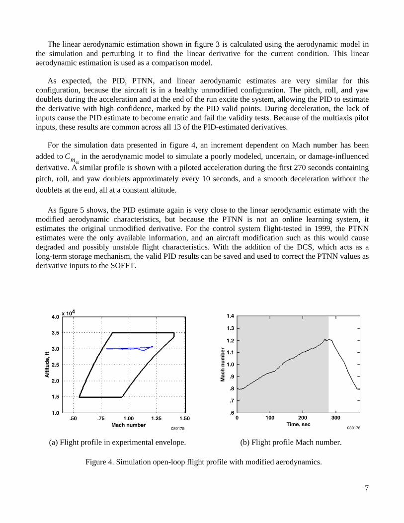
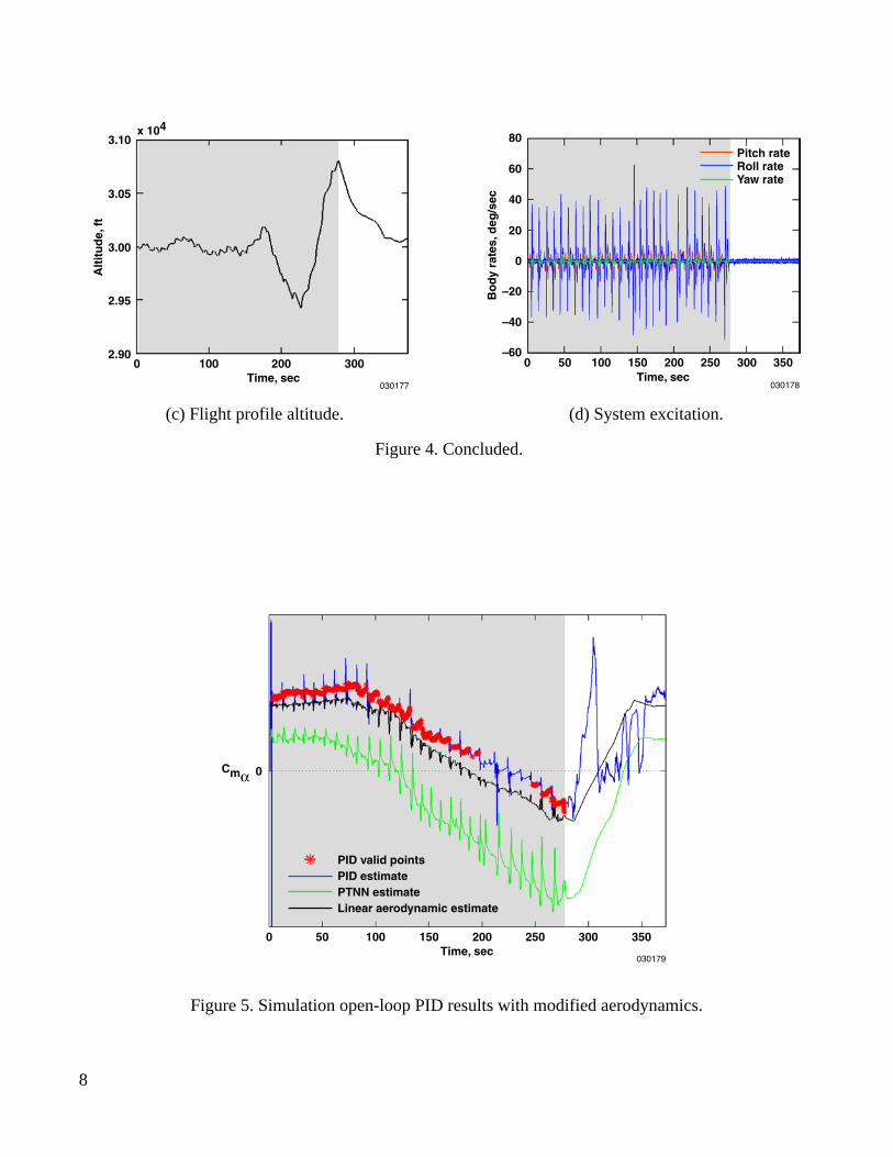
For the simulation data presented in figure 4, an increment dependent on Mach number has been
added to in the aerodynamic model to simulate a poorly modeled, uncertain, or damage-influenced
derivative. A similar profile is shown with a piloted acceleration during the first 270 seconds containing
pitch, roll, and yaw doublets approximately every 10 seconds, and a smooth deceleration without the
doublets at the end, all at a constant altitude.
As figure 5 shows, the PID estimate again is very close to the linear aerodynamic estimate with themodified aerodynamic characteristics, but because the PTNN is not an online learning system, itestimates the original unmodified derivative. For the control system flight-tested in 1999, the PTNNestimates were the only available information, and an aircraft modification such as this would causedegraded and possibly unstable flight characteristics. With the addition of the DCS, which acts as along-term storage mechanism, the valid PID results can be saved and used to correct the PTNN values asderivative inputs to the SOFFT.
Cmα
Alt
itu
de,
ft
4.0x 10⁴
.50
030175
.75 1.00Mach number
1.25 1.50
3.5
3.0
2.5
2.0
1.5
1.0
Mac
hn
um
ber
1.4
100Time, sec
030176
200 3000
1.3
1.2
1.1
1.0
.9
.8
.7
.6
(a) Flight profile in experimental envelope. (b) Flight profile Mach number.
Figure 4. Simulation open-loop flight profile with modified aerodynamics.
8
0
150Time, sec
0 50 100 200 250 300
Cmα
030179
350
PID valid pointsPID estimatePTNN estimateLinear aerodynamic estimate
Alt
itu
de,
ft
3.10x 10⁴
100
030177
3.05
3.00
2.95
2.90200
Time, sec3000
Bo
dy
rate
s,d
eg/s
ec
80
030178
300200100Time, sec
0 50
–20
–40
–60
0
20
40
60Pitch rateRoll rateYaw rate
150 250 350
(c) Flight profile altitude. (d) System excitation.
Figure 4. Concluded.
Figure 5. Simulation open-loop PID results with modified aerodynamics.
9
DYNAMIC CELL STRUCTURE NEURAL NETWORK (DCS)
The role of the DCS is to use valid information from the PID to store and recall an estimate of thederivative increment based on the current flight conditions. The derivative increment learned by the DCSis the PID estimate minus an averaged PTNN estimate over the same PID window of data. The flightconditions and surface positions are average values corresponding to the window of data used by the PIDto calculate the derivative estimate. When information is recalled from the DCS, flight conditions andsurface positions are used as inputs, and the outputs are added to the instantaneous PTNN estimates andfed to the SOFFT controller. These corrected derivatives are used to update the model that is used by thecontroller to calculate surface gains.
To use the DCS as the online learning mechanism in this system, many modifications to the genericalgorithm were necessary. The original DCS contained all 26 derivative increments in 1 very largenetwork, resulting in extensive training time and undesirable interaction between different axes. Anindividual network for each derivative increment was deemed too computationally expensive, so the finalconfiguration involved grouping the derivative increments by axis (the three moments, side force, andnormal force) for a total of five networks. Creating additional difficulty is the fact that validity isindependently calculated for each derivative increment, and all increments in an axis are not always validat the same instant. Because training is important whenever a derivative increment is valid, if otherderivative increments in that axis are invalid, they are marked as unknown so they will not adverselyeffect the network. All calculations are done on the current valid derivative increments only, and if noneexist for that axis, no training is performed.
A very important ability of the network is to scale both the independent and dependent inputs beforecalculations are done. This ability allows for adjusting the importance of inputs for determination oferrors, node addition location, and recall of derivative increments from the network. Typically, Machnumber is scaled to be the most important, followed by angle of attack, with sideslip, altitude, and surfacepositions of lesser importance. The typical topology of the network mainly depends on the independentinputs as in a typical aerodynamic table formulation, but more nodes are also desirable in areas where thederivative increments are rapidly changing as in the transonic range. The scaling of the derivativeincrements is an involved process and very dependent on the input data used. Fortunately, like the PID,the DCS has a configuration file to adjust many of the important parameters including the scalingbetween flights. An initial set of scaling values has been chosen, but when in-flight testing begins,updates are expected for optimal performance.
Included in the configuration file are other values that can be independently modified per axis andaffect the internal operation of the DCS. The way data are inserted into the training set and criteria forwhat data are inserted is controlled by two of the values in the configuration file. The error level foradding a new node, edge forgetting behavior, and amount of adaptation for best matching andneighboring nodes are also included. These values control the topology, size, speed, adaptability, andlong-term storage behavior of the neural network.
All the network data are periodically saved during testing. Between runs the network can be reset to azero condition, restored to a previously saved network, or allowed to continue training. Currently, whentraining occurs from a zero condition, and the first derivative increment is valid, all zero nodes are set tothese initial values. For any derivative increments that are not valid, all nodes receive that increment setas soon as validity is achieved. This method decreases the initial response time of the DCS and eliminates
10
the condition of having nodes near the untrained zero condition. Before this modification wasimplemented, the recall data would occasionally jump to the insufficiently trained nodes, causingunfavorable results.
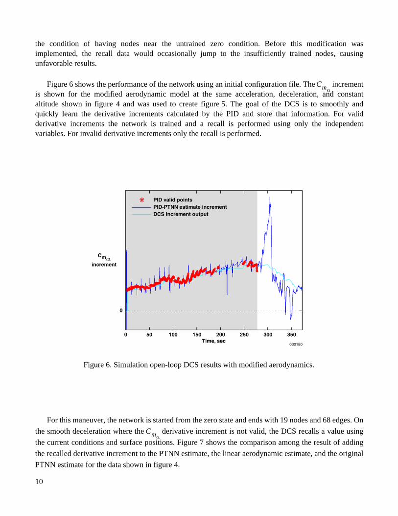
Figure 6 shows the performance of the network using an initial configuration file. The incrementis shown for the modified aerodynamic model at the same acceleration, deceleration, and constantaltitude shown in figure 4 and was used to create figure 5. The goal of the DCS is to smoothly andquickly learn the derivative increments calculated by the PID and store that information. For validderivative increments the network is trained and a recall is performed using only the independentvariables. For invalid derivative increments only the recall is performed.
For this maneuver, the network is started from the zero state and ends with 19 nodes and 68 edges. On
the smooth deceleration where the derivative increment is not valid, the DCS recalls a value using
the current conditions and surface positions. Figure 7 shows the comparison among the result of adding
the recalled derivative increment to the PTNN estimate, the linear aerodynamic estimate, and the original
PTNN estimate for the data shown in figure 4.
Cmα
0
150Time, sec
0 50 100 200 250 300
Cmαincrement
030180
350
PID valid pointsPID-PTNN estimate incrementDCS increment output
Figure 6. Simulation open-loop DCS results with modified aerodynamics.
Cmα

11
Figure 7. Simulation open-loop total estimated derivative with modified aerodynamics.
In a closed-loop configuration, the total estimate is sent to the SOFFT controller to update the model.Figure 7 illustrates how, at 4 seconds into the maneuver when the PID gives the DCS the first validderivative increment, the total estimate quickly jumps to a value close to the linear aerodynamic estimatefrom the simulation. On the deceleration when the PID estimate is invalid because of insufficientfrequency information, the DCS successfully recalls the correct derivative increment. The roughnessduring the excitation phase comes from the PTNN, which is dependent on aircraft states and surfacepositions. The total estimated derivative is simply the sum of the PTNN estimate and the DCS derivativeincrement estimate.
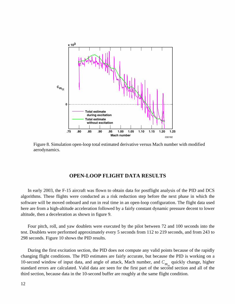
Figure 8 shows the total estimated as a function of Mach number. This figure illustrates theability of the DCS to learn the valid derivative increment during the training portion of the flight andsmoothly recall an estimate of the derivative increment when the PID estimates are invalid.
Cmα
Cmα
12
OPEN-LOOP FLIGHT DATA RESULTS
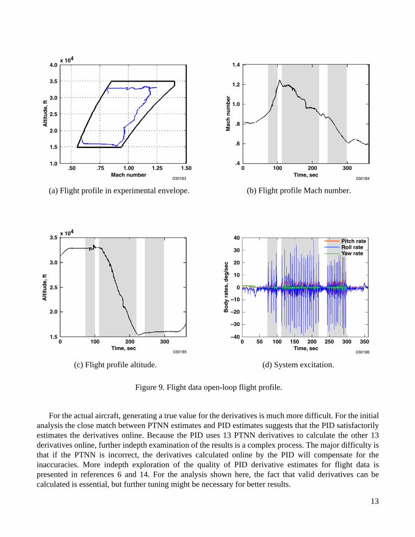
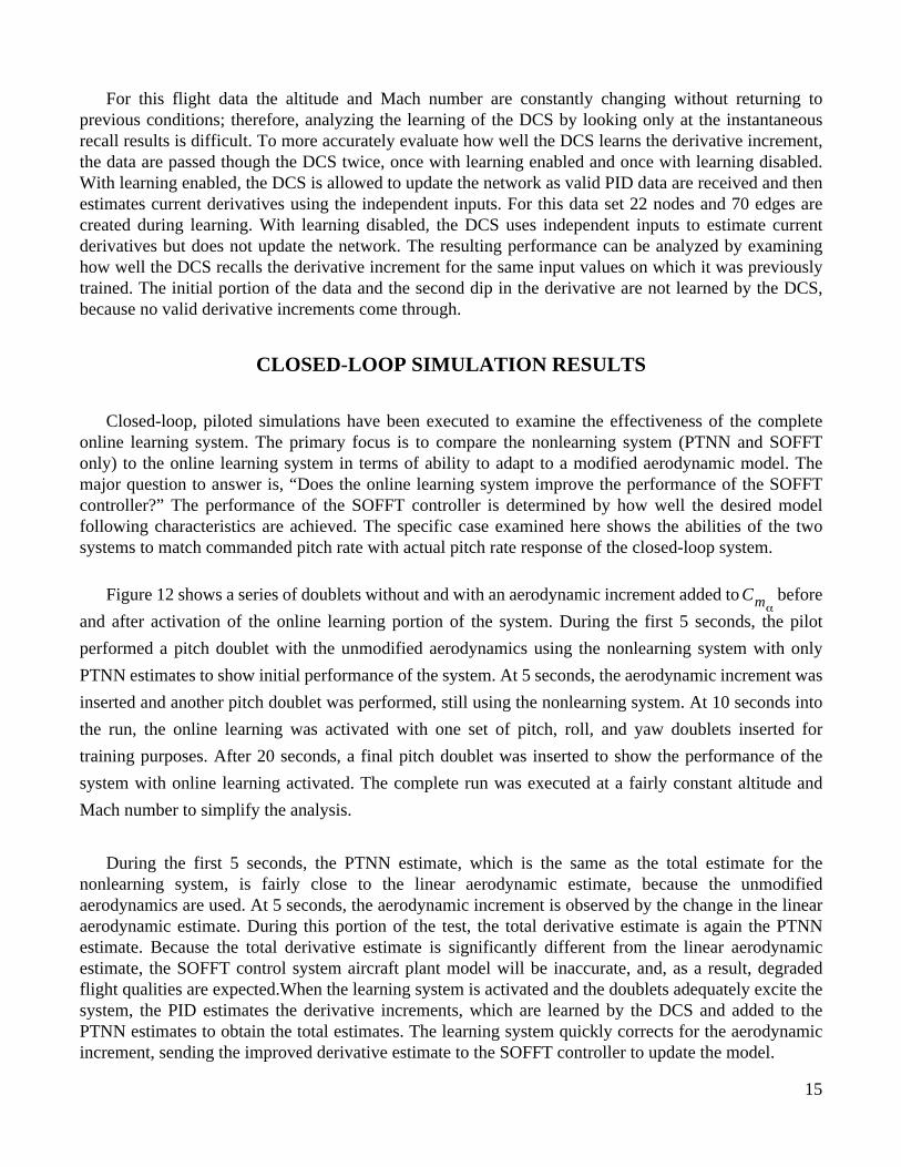
In early 2003, the F-15 aircraft was flown to obtain data for postflight analysis of the PID and DCSalgorithms. These flights were conducted as a risk reduction step before the next phase in which thesoftware will be moved onboard and run in real time in an open-loop configuration. The flight data usedhere are from a high-altitude acceleration followed by a fairly constant dynamic pressure decent to loweraltitude, then a deceleration as shown in figure 9.
Four pitch, roll, and yaw doublets were executed by the pilot between 72 and 100 seconds into thetest. Doublets were performed approximately every 5 seconds from 112 to 219 seconds, and from 243 to298 seconds. Figure 10 shows the PID results.
During the first excitation section, the PID does not compute any valid points because of the rapidlychanging flight conditions. The PID estimates are fairly accurate, but because the PID is working on a10-second window of input data, and angle of attack, Mach number, and quickly change, higherstandard errors are calculated. Valid data are seen for the first part of the second section and all of thethird section, because data in the 10-second buffer are roughly at the same flight condition.
Total estimateduring excitation
Total estimatewithout excitation
.75
0
x 103
.80 .85 .90 .95 1.00Mach number
1.05 1.10 1.15 1.20
030182
1.25
Cmα
Figure 8. Simulation open-loop total estimated derivative versus Mach number with modifiedaerodynamics.
Cmα
13
For the actual aircraft, generating a true value for the derivatives is much more difficult. For the initialanalysis the close match between PTNN estimates and PID estimates suggests that the PID satisfactorilyestimates the derivatives online. Because the PID uses 13 PTNN derivatives to calculate the other 13derivatives online, further indepth examination of the results is a complex process. The major difficulty isthat if the PTNN is incorrect, the derivatives calculated online by the PID will compensate for theinaccuracies. More indepth exploration of the quality of PID derivative estimates for flight data ispresented in references 6 and 14. For the analysis shown here, the fact that valid derivatives can becalculated is essential, but further tuning might be necessary for better results.
Alt
itu
de,
ft
4.0x 10⁴
.50
030183
.75 1.00Mach number
1.25 1.50
3.5
3.0
2.5
2.0
1.5
1.0
(a) Flight profile in experimental envelope.
Mac
hn
um
ber
1.4
100Time, sec
030184
200 3000
1.2
1.0
.8
.6
.4
(b) Flight profile Mach number.
Alt
itu
de,
ft
3.5x 10⁴
100
030185
3.0
2.5
2.0
1.5200
Time, sec3000
Bo
dy
rate
s,d
eg/s
ec
40
20
30
10
030186
300200100Time, sec
0 50 150 250 350
0
–20
–30
–10
–40
Pitch rateRoll rateYaw rate
(d) System excitation.(c) Flight profile altitude.
Figure 9. Flight data open-loop flight profile.

14
Figure 10. Flight data open-loop PID results.
Figure 11 shows the DCS performance on the derivative increment for the same flight maneuver
shown in figure 9. Because the research portion of the initial flights were primarily conducted to gather
data for PID analysis, DCS maneuvers comparable to those shown during the simulation data analysis are
not available.
Figure 11. Flight data open-loop DCS results.
0
150Time, sec
0 50 100 200 250 300 350
Cmα
030187
PID valid pointsPID estimatePTNN estimate
Cmα
0Cmα
030188
150Time, sec
0 50 100 200 250 300 350
PID valid pointsDCS increment recall onlyDCS increment outputPID-PTNN estimate increment
15
For this flight data the altitude and Mach number are constantly changing without returning toprevious conditions; therefore, analyzing the learning of the DCS by looking only at the instantaneousrecall results is difficult. To more accurately evaluate how well the DCS learns the derivative increment,the data are passed though the DCS twice, once with learning enabled and once with learning disabled.With learning enabled, the DCS is allowed to update the network as valid PID data are received and thenestimates current derivatives using the independent inputs. For this data set 22 nodes and 70 edges arecreated during learning. With learning disabled, the DCS uses independent inputs to estimate currentderivatives but does not update the network. The resulting performance can be analyzed by examininghow well the DCS recalls the derivative increment for the same input values on which it was previouslytrained. The initial portion of the data and the second dip in the derivative are not learned by the DCS,because no valid derivative increments come through.
CLOSED-LOOP SIMULATION RESULTS
Closed-loop, piloted simulations have been executed to examine the effectiveness of the completeonline learning system. The primary focus is to compare the nonlearning system (PTNN and SOFFTonly) to the online learning system in terms of ability to adapt to a modified aerodynamic model. Themajor question to answer is, “Does the online learning system improve the performance of the SOFFTcontroller?” The performance of the SOFFT controller is determined by how well the desired modelfollowing characteristics are achieved. The specific case examined here shows the abilities of the twosystems to match commanded pitch rate with actual pitch rate response of the closed-loop system.
Figure 12 shows a series of doublets without and with an aerodynamic increment added to before
and after activation of the online learning portion of the system. During the first 5 seconds, the pilot
performed a pitch doublet with the unmodified aerodynamics using the nonlearning system with only
PTNN estimates to show initial performance of the system. At 5 seconds, the aerodynamic increment was
inserted and another pitch doublet was performed, still using the nonlearning system. At 10 seconds into
the run, the online learning was activated with one set of pitch, roll, and yaw doublets inserted for
training purposes. After 20 seconds, a final pitch doublet was inserted to show the performance of the
system with online learning activated. The complete run was executed at a fairly constant altitude and
Mach number to simplify the analysis.
During the first 5 seconds, the PTNN estimate, which is the same as the total estimate for thenonlearning system, is fairly close to the linear aerodynamic estimate, because the unmodifiedaerodynamics are used. At 5 seconds, the aerodynamic increment is observed by the change in the linearaerodynamic estimate. During this portion of the test, the total derivative estimate is again the PTNNestimate. Because the total derivative estimate is significantly different from the linear aerodynamicestimate, the SOFFT control system aircraft plant model will be inaccurate, and, as a result, degradedflight qualities are expected.When the learning system is activated and the doublets adequately excite thesystem, the PID estimates the derivative increments, which are learned by the DCS and added to thePTNN estimates to obtain the total estimates. The learning system quickly corrects for the aerodynamicincrement, sending the improved derivative estimate to the SOFFT controller to update the model.
Cmα

16
Figure 12. Simulation closed-loop total estimated derivative.
Figure 13 shows the actual pitch rate of the system compared to the commanded pitch rate. Theclosed-loop results of the nonlearning and learning systems are observed for the complete system.
Figure 13. Simulation closed-loop pitch performance.
Non-learningsystem,standardaerodynamics
Non-learningsystem, withaerodynamicincrement
Learning system,training segment,with aerodynamicincrement
Learning system,training complete,with aerodynamicincrement
OriginalPTNN error
Aerodynamicincrement
Learnedincrement
Linear aerodynamic estimatePTNN estimateTotal estimate
15Time, sec
0 5 10 20 25
Cmα
030189
Non-learningsystem,standardaerodynamics
Non-learningsystem,withaerodynamicincrement
Learning system,training segment,with aerodynamicincrement
Learning system,training complete,with aerodynamicincrement
Pitch, roll,yaw doublet
Cmα increment inserted
Actual pitch rateCommanded pitch rate
15Time, sec
0
20
5 10 20 3025
Pitch rate,deg/sec
030190
15
10
5
0
–5
–10
–15
–20
17
For the unmodified aerodynamics during the first doublet, the nonlearning system response is a fairlyclose match to the command. The second doublet shows that the nonlearning system has degradedcontrol characteristics, and the response is significantly different from the command because of theaerodynamic modification. During the pitch, roll, and yaw doublets the online learning systemimmediately starts to improve the response of the aircraft. After exciting the system, the final pitchdoublet shows excellent performance.
The performance improvement that occurs with the learning system and modified aerodynamicsemphasizes that the PTNN does not exactly match the aerodynamic model in the standard simulation. Aspreviously discussed, the suspected cause is that the PTNN was trained on an aerodynamic model usingthe original wind-tunnel model with rectangular engine nozzles. Although the PTNN is not perfectlyaccurate, the complete response of the online learning system compensates for both the PTNNinaccuracies and the modified aerodynamics, resulting in better performance than is achieved withoutlearning.
CONCLUDING REMARKS
The online real-time parameter identification (PID) algorithm and dynamic cell structure neuralnetwork (DCS) have been successfully integrated in preparation for flight demonstration. This indirectadaptive system has worked well in the open-loop simulation data and flight data cases and theclosed-loop simulation tests. The PID has demonstrated the ability to estimate the aerodynamic stabilityand control derivatives in real time in the flight environment. The DCS has demonstrated the ability toefficiently and effectively train and recall the derivative increment information. As a complete system,the online PID algorithm and DCS have produced promising results in a closed-loop simulationenvironment. The online learning system is being installed on the F-15 research aircraft for open-loop,in-flight testing. During this phase of flight tests, different properties of the PID and DCS can be exploredon and offline through modifying configuration files over various flight conditions and pilot maneuvers.In-flight performance of the PID can be analyzed for estimation accuracy and validity testing. Continuedeffort is needed, but with further testing and analysis this system has the potential for effective use inflight projects requiring adaptive flight control systems.
REFERENCES
1. Kaneshige, John, and Karen Gundy-Burlet, “Integrated Neural Flight and Propulsion ControlSystem,” AIAA-2001-4386, Aug. 2001.
2. Gundy-Burlet, Karen, K. Krishnakumar, Greg Limes, and Don Bryant, “Control ReallocationStrategies for Damage Adaptation in Transport Class Aircraft,”
AIAA Guidance, Navigation, andControl Conference and Exhibit,
AIAA-2003-5642, Aug. 2003.
3. Krishnakumar, K., G. Limes, K. Gundy-Burlet, and D. Bryant, “An Adaptive Critic Approach toReference Model Adaptation,”
AIAA Guidance, Navigation, and Control Conference and Exhibit,
AIAA-2003-5790, Aug. 2003.
4. Norgaard, Magnus, Charles C. Jorgensen, and James C. Ross,
Neural Network Prediction of NewAircraft Design Coefficients
, NASA TM-112197, May 1997.

18
5. Morelli, Eugene A., “Real-Time Parameter Estimation in the Frequency Domain,”
AIAAAtmospheric Flight Mechanics Conference
, AIAA-99-4043, Aug. 1999.
6. Smith, Mark S., Timothy R. Moes, and Eugene A. Morelli, “Real-Time Stability and ControlDerivative Extraction from F-15 Flight Data,”
AIAA Atmospheric Flight Mechanics Conference
,AIAA-2003-5701, Aug. 2003.
7. Ahrns, Ingo, Jörg Bruske, and Gerald Sommer, “On-line Learning with Dynamic Cell Structures,”
Proceedings of ICANN’95
, vol. 2, 1995, pp.141–146.
8. Jorgensen, Charles C.,
Direct Adaptive Aircraft Control Using Dynamic Cell Structure NeuralNetworks
, NASA TM-112198, May 1997.
9. Halyo, Nesim, and Haldun Direskeneli,
A Stochastic Optimal Feedforward and Feedback ControlMethodology for Superagility
, NASA CR-4471, 1992.
10. Halyo, Nesim,
Integrated Control Using the SOFFT Control Structure
, NASA CR-4748, July 1996.
11. Urnes, James, Sr., Ron Davidson, Steve Jacobson, “A Damage Adaptive Flight Control SystemUsing Neural Network Technology,”
2001 American Control Conference
, June 2001.
12. Lee, Chong O., Michael P. Thomson, and James M. Urnes, Sr., “Development of aNeural-Network-Based Fault-Tolerant Adaptive Flight Control System,”
2001 American ControlConference
, June 2001.
13. Norlin, Ken A.,
Flight Simulation Software at NASA Dryden Flight Research Center
, NASATM-104315, Oct. 1995.
14. Moes, Timothy R., Mark S. Smith, and Eugene A. Morelli, “Flight Investigation of PrescribedSimultaneous Independent Surface Excitations (PreSISE) for Real-Time Stability and ControlDerivative Estimation,”
AIAA Atmospheric Flight Mechanics Conference
, AIAA-2003-5702, Aug.2003.
REPORT DOCUMENTATION PAGE
Form ApprovedOMB No. 0704-0188
Public reporting burden for this collection of information is estimated to average 1 hour per response, including the time for reviewing instructions, searching existing data sources, gathering andmaintaining the data needed, and completing and reviewing the collection of information. Send comments regarding this burden estimate or any other aspect of this collection of information,including suggestions for reducing this burden, to Washington Headquarters Services, Directorate for Information Operations and Reports, 1215 Jefferson Davis Highway, Suite 1204, Arlington,VA 22202-4302, and to the Office of Management and Budget, Paperwork Reduction Project (0704-0188), Washington, DC 20503.
1. AGENCY USE ONLY (Leave blank) 2. REPORT DATE 3. REPORT TYPE AND DATES COVERED
4. TITLE AND SUBTITLE 5. FUNDING NUMBERS
6. AUTHOR(S)
8. PERFORMING ORGANIZATION REPORT NUMBER
7. PERFORMING ORGANIZATION NAME(S) AND ADDRESS(ES)
9. SPONSORING/MONITORING AGENCY NAME(S) AND ADDRESS(ES) 10. SPONSORING/MONITORING AGENCY REPORT NUMBER
11. SUPPLEMENTARY NOTES
12a. DISTRIBUTION/AVAILABILITY STATEMENT 12b. DISTRIBUTION CODE
13. ABSTRACT (Maximum 200 words)
14. SUBJECT TERMS 15. NUMBER OF PAGES
16. PRICE CODE
17. SECURITY CLASSIFICATION OF REPORT
18. SECURITY CLASSIFICATION OF THIS PAGE
19. SECURITY CLASSIFICATION OF ABSTRACT
20. LIMITATION OF ABSTRACT
NSN 7540-01-280-5500 Standard Form 298 (Rev. 2-89)
Prescribed by ANSI Std. Z39-18298-102
Integration of Online Parameter Identification and Neural Network forIn-Flight Adaptive Control
WU 745-20-00-SE-40-00-IFS
Jacob J. Hageman, Mark S. Smith, and Susan Stachowiak
NASA Dryden Flight Research CenterP.O. Box 273Edwards, California 93523-0273
H-2543
National Aeronautics and Space AdministrationWashington, DC 20546-0001 NASA/TM-2003-212028
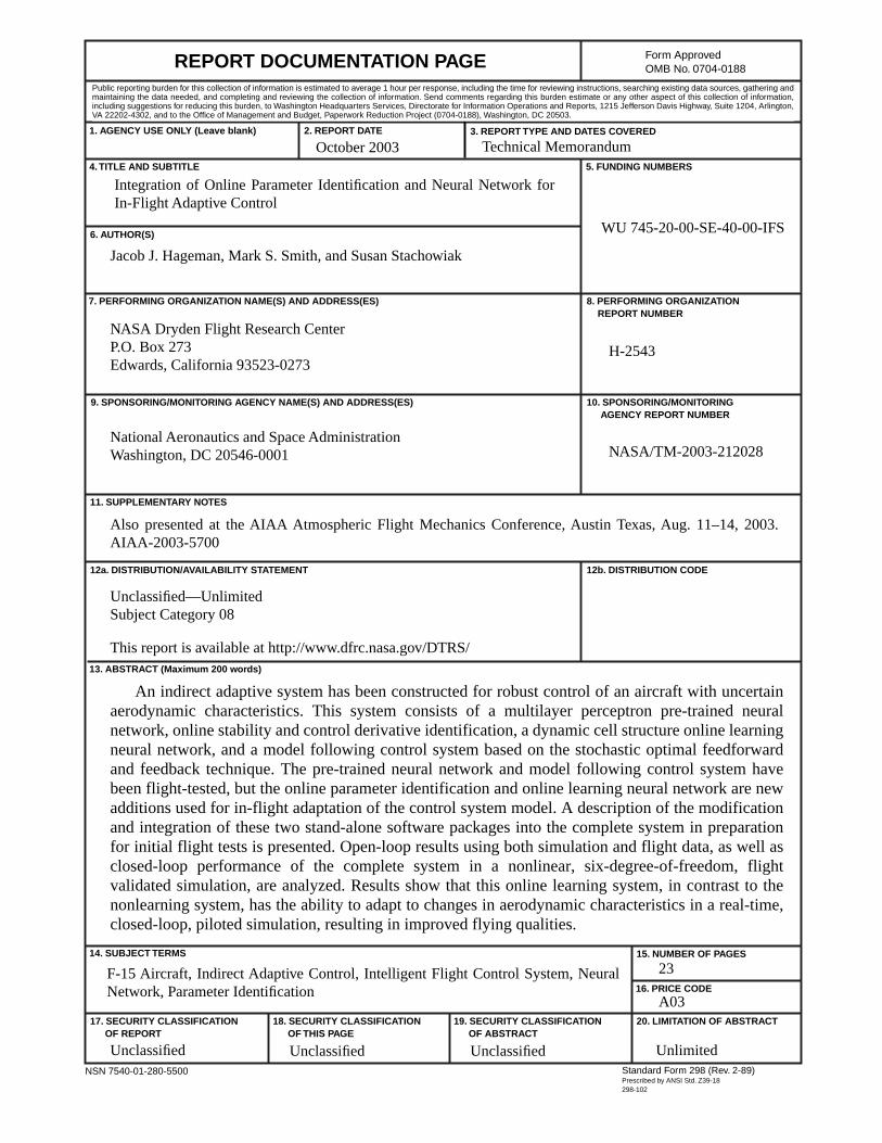
An indirect adaptive system has been constructed for robust control of an aircraft with uncertainaerodynamic characteristics. This system consists of a multilayer perceptron pre-trained neuralnetwork, online stability and control derivative identification, a dynamic cell structure online learningneural network, and a model following control system based on the stochastic optimal feedforwardand feedback technique. The pre-trained neural network and model following control system havebeen flight-tested, but the online parameter identification and online learning neural network are newadditions used for in-flight adaptation of the control system model. A description of the modificationand integration of these two stand-alone software packages into the complete system in preparationfor initial flight tests is presented. Open-loop results using both simulation and flight data, as well asclosed-loop performance of the complete system in a nonlinear, six-degree-of-freedom, flightvalidated simulation, are analyzed. Results show that this online learning system, in contrast to thenonlearning system, has the ability to adapt to changes in aerodynamic characteristics in a real-time,closed-loop, piloted simulation, resulting in improved flying qualities.
F-15 Aircraft, Indirect Adaptive Control, Intelligent Flight Control System, NeuralNetwork, Parameter Identification
A03
23
Unclassified Unclassified Unclassified Unlimited
October 2003 Technical Memorandum
Also presented at the AIAA Atmospheric Flight Mechanics Conference, Austin Texas, Aug. 11–14, 2003.AIAA-2003-5700
Unclassified—UnlimitedSubject Category 08
This report is available at http://www.dfrc.nasa.gov/DTRS/