Embed Size (px)
Citation preview

Intelligent Event Processor (IEP)User's Guide
Part No: 821–1070–11February 2009

Copyright ©2010 Sun Microsystems, Inc. 4150 Network Circle, Santa Clara, CA 95054 U.S.A. All rights reserved.
Sun Microsystems, Inc. has intellectual property rights relating to technology embodied in the product that is described in this document. In particular, and withoutlimitation, these intellectual property rights may include one or more U.S. patents or pending patent applications in the U.S. and in other countries.
U.S. Government Rights – Commercial software. Government users are subject to the Sun Microsystems, Inc. standard license agreement and applicable provisionsof the FAR and its supplements.
This distribution may include materials developed by third parties.
Parts of the product may be derived from Berkeley BSD systems, licensed from the University of California. UNIX is a registered trademark in the U.S. and othercountries, exclusively licensed through X/Open Company, Ltd.
Sun, Sun Microsystems, the Sun logo, the Solaris logo, the Java Coffee Cup logo, docs.sun.com, Java, and Solaris are trademarks or registered trademarks of SunMicrosystems, Inc. or its subsidiaries in the U.S. and other countries. All SPARC trademarks are used under license and are trademarks or registered trademarks ofSPARC International, Inc. in the U.S. and other countries. Products bearing SPARC trademarks are based upon an architecture developed by Sun Microsystems, Inc.
The OPEN LOOK and SunTM Graphical User Interface was developed by Sun Microsystems, Inc. for its users and licensees. Sun acknowledges the pioneering effortsof Xerox in researching and developing the concept of visual or graphical user interfaces for the computer industry. Sun holds a non-exclusive license from Xerox tothe Xerox Graphical User Interface, which license also covers Sun's licensees who implement OPEN LOOK GUIs and otherwise comply with Sun's written licenseagreements.
Products covered by and information contained in this publication are controlled by U.S. Export Control laws and may be subject to the export or import laws inother countries. Nuclear, missile, chemical or biological weapons or nuclear maritime end uses or end users, whether direct or indirect, are strictly prohibited. Exportor reexport to countries subject to U.S. embargo or to entities identified on U.S. export exclusion lists, including, but not limited to, the denied persons and speciallydesignated nationals lists is strictly prohibited.
DOCUMENTATION IS PROVIDED “AS IS” AND ALL EXPRESS OR IMPLIED CONDITIONS, REPRESENTATIONS AND WARRANTIES, INCLUDING ANYIMPLIED WARRANTY OF MERCHANTABILITY, FITNESS FOR A PARTICULAR PURPOSE OR NON-INFRINGEMENT, ARE DISCLAIMED, EXCEPT TOTHE EXTENT THAT SUCH DISCLAIMERS ARE HELD TO BE LEGALLY INVALID.
100217@23474

Contents
1 Designing Intelligent Event Processor (IEP) Projects ...................................................................... 7Intelligent Event Processor Overview ..................................................................................................8
Complex Event Processing and Event Stream Processing .........................................................8Typical IEP Scenarios .....................................................................................................................9IEP Architecture ..............................................................................................................................9IEP Design-Time and Runtime Components .......................................................................... 10
Basic Workflow .................................................................................................................................... 12Creating an Intelligent Event Processing Module Project ...................................................... 12Adding and Configuring IEP Operators ................................................................................... 13Disabling the Generation of Bindings and Services ................................................................. 14Validating Event Processors ....................................................................................................... 15Creating and Deploying the Composite Application Project ................................................. 15
Introduction to IEP Operators ........................................................................................................... 17Understanding Schemas ............................................................................................................. 17Understanding Streams ............................................................................................................... 18Understanding Relations ............................................................................................................ 18Supported Data Types ................................................................................................................. 19IEP Operator Inputs and Outputs .............................................................................................. 20
Aggregator Operators ......................................................................................................................... 20Relation Aggregator ..................................................................................................................... 21Time Based Aggregator ............................................................................................................... 22Tuple Based Aggregator .............................................................................................................. 23
Correlation and Filter Operators ....................................................................................................... 24Relation Map ................................................................................................................................ 24Stream Projection and Filter ....................................................................................................... 25Tuple Serial Correlation .............................................................................................................. 28
Input Operators ................................................................................................................................... 28External Table Polling Stream .................................................................................................... 28
3

Replay Stream ............................................................................................................................... 30Stream Input ................................................................................................................................. 32Table Input .................................................................................................................................... 33
Output Operators ................................................................................................................................ 34Batched Stream Output ............................................................................................................... 34Invoke Stream ............................................................................................................................... 35Relation Output ........................................................................................................................... 36Save Stream ................................................................................................................................... 36Stream Output .............................................................................................................................. 38Table Output ................................................................................................................................ 39
Relation Converter Operators ........................................................................................................... 39Delete Stream ............................................................................................................................... 39Insert Stream ................................................................................................................................. 40Notification Stream ...................................................................................................................... 41Relation Stream ............................................................................................................................ 42
Relation Operators .............................................................................................................................. 42Distinct .......................................................................................................................................... 42Intersect ......................................................................................................................................... 43Minus ............................................................................................................................................. 44Union ............................................................................................................................................. 45Union All ....................................................................................................................................... 45
Sequence Operators ............................................................................................................................ 46Contiguous Order ........................................................................................................................ 46Gap Window ................................................................................................................................ 48
Stream Converter Operators .............................................................................................................. 49Attribute Based Window ............................................................................................................. 49Partitioned Window .................................................................................................................... 50Time Based Window ................................................................................................................... 51Tuple Based Window .................................................................................................................. 52
WSDL Documents in IEP Module Projects ..................................................................................... 53Data Types in the WSDL Document ......................................................................................... 53Message Objects in the WSDL Document ................................................................................ 55Bindings and Services in the WSDL Document ....................................................................... 56
Understanding the IEP Database ...................................................................................................... 58Configuring the IEP Database to Use Oracle ............................................................................ 60Configuring the IEP Database to Use MySQL .......................................................................... 66
Contents
Intelligent Event Processor (IEP) User's Guide • February 20094

IEP Service Engine-Specific Database Tables ........................................................................... 71Event Process-Specific Database Tables .................................................................................... 72Operator-Specific Database Tables ............................................................................................ 73
Configuring Message Reliability in an IEP Module Project ........................................................... 74▼ To Disable Message Reliability for Outbound Messages ......................................................... 75
Index ......................................................................................................................................................77
Contents
5

6

Designing Intelligent Event Processor (IEP)Projects
The topics listed here provide information about how to use the Intelligent Event Processor(IEP).
If you have any questions or problems, see the Java CAPS web site at http://goldstar.stc.com/support.
What You Need to Know
■ “Intelligent Event Processor Overview” on page 8
What You Need to Do
■ “Basic Workflow” on page 12■ “Introduction to IEP Operators” on page 17■ “Aggregator Operators” on page 20■ “Correlation and Filter Operators” on page 24■ “Input Operators” on page 28■ “Output Operators” on page 34■ “Relation Converter Operators” on page 39■ “Relation Operators” on page 42■ “Sequence Operators” on page 46■ “Stream Converter Operators” on page 49■ “WSDL Documents in IEP Module Projects” on page 53■ “Understanding the IEP Database” on page 58■ “Configuring Message Reliability in an IEP Module Project” on page 74
1C H A P T E R 1
7

Intelligent Event Processor OverviewThe Intelligent Event Processor (IEP) enables you to perform complex event processing (CEP)and event stream processing (ESP) from within an enterprise service bus.
■ “Complex Event Processing and Event Stream Processing” on page 8■ “Typical IEP Scenarios” on page 9■ “IEP Architecture” on page 9■ “IEP Design-Time and Runtime Components” on page 10
Complex Event Processing and Event StreamProcessingIn the most general sense, the term event refers to anything that happens in a system. Forexample:
■ A password change■ A stock purchase■ A transfer of funds
You use IEP to process computerized representations of these events.
These events are generated and sent out by applications. The applications can be located withinthe enterprise service bus, or they can come from an external system that is connected to theenterprise service bus.
The term event stream refers to a continuous set of events. For example, an event stream couldcontain the password changes made by the users of a web-based application.
Processing an event stream can involve many types of activities. For example:
■ You can examine a bounded portion of an event stream, such as all of the events thatoccurred in the last two minutes. This bounded portion is called a window.
■ You can apply a function to a set of events. For example, you can determine the averageprice of a stock during the last three hours, with the calculation updated every five minutes.
■ You can change the order of the events.
When you combine multiple events to create a higher level event, the result is called a complexevent.
An architectural style in which software modules operate in response to the arrival of events iscalled event driven architecture.
Intelligent Event Processor Overview
Intelligent Event Processor (IEP) User's Guide • February 20098

Typical IEP ScenariosThe following table describes typical IEP scenarios.
Scenario Example
Financial trade auditing andcompliance
Examine a stream of stock transactions and find any transactions thatare suspicious. Check whether any traders involved in a suspicioustransaction also appear in a database table that contains the names ofpersons of interest.
Network monitoring and trafficengineering
Receive an undifferentiated stream of alerts from various hardwaredevices, group them by the device, and sort them by the unique ID. Foreach device, detect any missing alerts and request them to be re-sent.
IT security event correlation Examine the password changes that have been made to a web-basedapplication. If the number of password changes in a given hour ismore than twice the average, then generate a security alert.
Asset management and tracking usingRFID
Examine the RFID signals that are regularly emitted by all of theproducts in a store. Determine whether a product is moving throughthe exit area without having been purchased. Determine whether aproduct's RFID emitter is no longer working.
IEP ArchitectureThe following diagram illustrates the IEP architecture.
Intelligent Event Processor Overview
Chapter 1 • Designing Intelligent Event Processor (IEP) Projects 9

Within the enterprise service bus, the IEP Service Engine can interact with any JavaTM BusinessIntegration (JBI) service engine or binding component that is also plugged into the bus. TheNormalized Message Router takes care of message exchanges between the components.
By default, the IEP Service Engine receives input events from the HTTP Binding Componentand sends output to the File Binding Component. The IEP Service Engine uses a database tomaintain information about deployed event processors.
IEP Design-Time and Runtime ComponentsIEP consists of a design-time component and a runtime component.■ The design-time component is integrated within the NetBeans IDE.■ The runtime component is implemented as a JBI service engine.
In the NetBeans IDE, you create an IEP Module project and then add one or more eventprocessors.
For each event processor, you drag operators from the palette onto the design canvas. In thepalette, the operators are grouped into the following categories: Aggregator, Correlation andFilter, Input, Output, Relation Converter, Relation, Sequence, and Stream Converter.
Database
IEPService Engine
HTTP BindingComponent
External ServiceConsumer
External ServiceProvider
JMX BasedAdmin Tools
File BindingComponent
BindingComponent
SystemManagement
Layer
Service Engine
Normalized Message Router
JBI Framework
Java SE/Java EE
Intelligent Event Processor Overview
Intelligent Event Processor (IEP) User's Guide • February 200910

An event processor must have at least one input operator and one output operator. You can addany number of operators between the input operator and the output operator.
On the design canvas, you connect the operators with each other and use property editors toconfigure the operators.
The following screen capture shows a set of operators in an event processor. The operator at theleft is an input operator. The operator at the right is an output operator.
Some operators allow you to enter SQL-like statements. For these operators, knowledge of theSQL SELECT statement can be useful.
When you save an IEP Module project, IEP generates a Web Services Description Language(WSDL) document for each event processor. The WSDL documents contain the endpoints forthe event processors.
You can run a set of predefined validation rules on an event processor at design time.
To deploy an IEP Module project, you must create and build a Composite Application project.These tasks create a service assembly. The service assembly is a collection of service unitsintended for the IEP Service Engine and any other required JBI component (such as the HTTPBinding Component and the File Binding Component).
Intelligent Event Processor Overview
Chapter 1 • Designing Intelligent Event Processor (IEP) Projects 11

When the project is deployed, the IEP Service Engine receives and processes the input events.
Basic WorkflowThis topic describes the basic workflow of IEP.
■ “Creating an Intelligent Event Processing Module Project” on page 12■ “Adding and Configuring IEP Operators” on page 13■ “Disabling the Generation of Bindings and Services” on page 14■ “Validating Event Processors” on page 15■ “Creating and Deploying the Composite Application Project” on page 15
Creating an Intelligent Event Processing ModuleProjectYou create a new Intelligent Event Processing Module project in the NetBeans IDE. You thenadd one or more event processors to the project.
The following screen capture shows an IEP Module project that has one event processor.
▼ To Create an Intelligent Event Processing Module Project
From the IDE's main menu, choose File → New Project.The New Project wizard opens.
In the Categories list, select the SOA node.
In the Projects list, select the Intelligent Event Processing Module node.
Click Next.
1
2
3
4
Basic Workflow
Intelligent Event Processor (IEP) User's Guide • February 200912

(Optional) In the Project Name field, change the default project name.
Click Finish.The new IEP Module project appears in the Projects window. You can now add one or moreevent processors to the project.
▼ To Add an Event Processor to the Project
Right-click the Processor Files node and choose New → Intelligent Event Processor.
(Optional) In the File Name field, change the default file name.
Click Finish.The event processor is added. The IEP Editor opens in Design view. You can now define theevent processing logic by adding and configuring IEP operators.
Adding and Configuring IEP OperatorsOnce you add an event processor to an IEP Module project, you define the event processinglogic by adding and configuring IEP operators.
An event processor must have at least one input operator.
An event processor must have at least one output operator.
You can add any number of operators between the input operator and the output operator.
The following screen capture shows a set of operators in an event processor. The operator at theleft is an input operator. The operator at the right is an output operator.
For general information about the IEP operators, see “Introduction to IEP Operators” onpage 17.
For specific information about each IEP operator, see the following topics:
■ “Aggregator Operators” on page 20
5
6
1
2
3
Basic Workflow
Chapter 1 • Designing Intelligent Event Processor (IEP) Projects 13

■ “Correlation and Filter Operators” on page 24■ “Input Operators” on page 28■ “Output Operators” on page 34■ “Relation Converter Operators” on page 39■ “Relation Operators” on page 42■ “Sequence Operators” on page 46■ “Stream Converter Operators” on page 49
▼ To Add IEP Operators to an Event Processor
If the Palette is not visible in the NetBeans IDE, then choose Window → Palette from the IDE'smain menu.
Drag the appropriate IEP operators from the Palette to the Design view.
▼ To Configure IEP Operators in an Event Processor
For each IEP operator that you added, do the following:
a. Double-click the operator. Alternately, you can click the operator, go to the Propertieswindow, and click the ellipsis.The property editor opens.
b. Edit the appropriate properties. For some operators, you can add or modify attributes.
c. (Optional) Click the Documentation tab and supply notes on this component.
d. Click OK.
Connect the operators to each other as appropriate.You send the output of one operator to the input of another operator by selecting the outputport of the first operator and dragging it to the input port of the second operator.
Disabling the Generation of Bindings and ServicesWhen you save an IEP Module project, IEP generates a Web Services Description Language(WSDL) document for each event processor. The WSDL documents contain the endpoints forthe event processors.
By default, the WSDL documents include concrete information (that is, bindings and services).You might need to manually update the default settings for any binding and service. Forexample, the default file directory is a Windows path, which would not work correctly on a
1
2
1
2
Basic Workflow
Intelligent Event Processor (IEP) User's Guide • February 200914
UNIX system. If you manually update the WSDL document and then save the IEP Moduleproject again, the changes that you made to the WSDL document are overwritten.
You can configure IEP to generate abstract WSDL documents instead. The bindings andservices are not included. With this approach, you can define the bindings and services by usingthe Composite Application Service Assembly (CASA) Editor. These bindings and services arenot affected by subsequent changes to the IEP Module project.
▼ To Disable the Generation of Bindings and Services
Go to the location of the IEP Module project and open the project.properties file.
Change the value of the always.generate.abstract.wsdl flag to true.
Save the project.properties file.
Validating Event ProcessorsYou can run a set of predefined validation rules on an event processor at design time. Thevalidation rules include:■ An event processor must have at least one input operator.■ An event processor must have at least one output operator.■ All of an operator's required properties must have values.■ If an attribute has a data type of VARCHAR, then the size must also be specified.
▼ To Validate Event Processors
In the NetBeans IDE, open the event processor that you want to validate.
Click the Validate XML icon at the top of the Design view.The results appear in the Output window.
If you switch to the Source view and click a validation error in the Output window, then thesource of the error is highlighted.
Creating and Deploying the Composite ApplicationProjectYou deploy an IEP Module project as part of a Composite Application project.
1
2
3
1
2
3
Basic Workflow
Chapter 1 • Designing Intelligent Event Processor (IEP) Projects 15

The Composite Application Service Assembly (CASA) Editor provides a visual interface forediting the deployment configuration of a Composite Application project. You can performsuch tasks as adding JBI module projects, adding and removing connections betweenendpoints, and adding concrete WSDL elements.
▼ To Create a Composite Application Project
From the IDE's main menu, choose File → New Project.The New Project wizard opens.
In the Categories list, select the SOA node.
In the Projects list, select the Composite Application node.
Click Next.
(Optional) In the Project Name field, change the default project name.
Click Finish.The new Composite Application project appears in the Projects window. In addition, the CASAEditor appears.
▼ To Add the IEP Module Project to the Composite Application Project
In the Projects window, right-click the Composite Application project and choose Add JBIModule.The Select Project dialog box appears.
Select the IEP Module project.
Click Add Project JAR Files.The IEP Module project is added to the JBI Modules area of the CASA Editor.
▼ To Define the Binding Components and Connections
If you generated an abstract WSDL document, then use the CASA Editor to define the bindingcomponents and connections.For detailed instructions, see the CASA Editor topics in the NetBeans IDE help.
If you generated a concrete WSDL document, then you can override the generated bindings bydeleting the connections and defining the new binding components and connections.
1
2
3
4
5
6
1
2
3
1
2
Basic Workflow
Intelligent Event Processor (IEP) User's Guide • February 200916

Caution – For both abstract and concrete WSDL documents, do not clone the WSDL documentto customize its generated bindings and services. Updates to the generated WSDL documentswill not be updated after the cloning. Over time, the cloned and edited WSDL documentdeployed for the bindings will become inconsistent with the WSDL document deployed for theIEP Service Engine.
▼ To Deploy the Composite Application Project
Right-click the Composite Application project and select Build.
Right-click the Composite Application project and select Deploy.
Wait until the BUILD SUCCESSFUL message appears in the Output window.You can now create test cases to ensure that the IEP Module project works as expected.
If you make additional changes to the IEP Module project, then you must rebuild and redeploythe Composite Application project.
Introduction to IEP OperatorsThe IEP operators enable you to define the logic in an event processor.
Most of the IEP operators take a stream or a relation as input and produce a stream or a relationas output.
■ “Understanding Schemas” on page 17■ “Understanding Streams” on page 18■ “Understanding Relations” on page 18■ “Supported Data Types” on page 19■ “IEP Operator Inputs and Outputs” on page 20
Understanding SchemasA schema defines the types of information that a set of data contains. A schema consists of oneor more attributes. Each attribute is identified by a name and has a data type that specifies theallowed values.
For example, a schema could consist of the following attributes:
■ An attribute called Symbol that allows character values of between 1 and 10 characters■ An attribute called Price that allows floating-point values
1
2
3
Introduction to IEP Operators
Chapter 1 • Designing Intelligent Event Processor (IEP) Projects 17

Understanding StreamsA stream is a series of timestamped events that have the same schema.
Assume that a stream has the following characteristics:
■ Each event represents a stock transaction.■ The schema consists of the stock symbol and the stock price.
The following table shows an example of the events in the stream during a brief interval of time.
Symbol Price Timestamp
ADBE 21.60 2008-12-15-T10:30:02:899-05.00
AMZN 50.12 2008-12-15-T10:32:44:674-05.00
ATT 23.88 2008-12-15-T10:35:17:198-05.00
ADBE 21.70 2008-12-15-T10:38:23:257-05.00
Understanding RelationsA relation is a collection of events that match a user-defined condition at a point in time.
You can define the condition in various ways. For example:
■ All events that arrived in the last five seconds■ All events that arrived in the last five hours■ The most recent two events
Assume that you define the condition as all events that arrived in the last five seconds. For theexample in “Understanding Streams” on page 18, the relation at time2008-12-15-T10:35:00:000-05.00 would consist of the following events.
Symbol Price Timestamp
ADBE 21.60 2008-12-15-T10:30:02:899-05.00
AMZN 50.12 2008-12-15-T10:32:44:674-05.00
Let's move forward one second in time. The relation at time 2008-12-15-T10:36:00:000-05.00would consist of the following events. Compared with the previous relation, one event hasdropped out and one event has been added.
Introduction to IEP Operators
Intelligent Event Processor (IEP) User's Guide • February 200918

Symbol Price Timestamp
AMZN 50.12 2008-12-15-T10:32:44:674-05.00
ATT 23.88 2008-12-15-T10:35:17:198-05.00
The relation at time 2008-12-15-T10:37:00:000-05.00 would consist of the following events.This relation has the same events as the previous relation.
Symbol Price Timestamp
AMZN 50.12 2008-12-15-T10:32:44:674-05.00
ATT 23.88 2008-12-15-T10:35:17:198-05.00
The relation at time 2008-12-15-T10:38:00:000-05.00 would consist of the following events.Compared with the previous relation, one event has dropped out.
Symbol Price Timestamp
ATT 23.88 2008-12-15-T10:35:17:198-05.00
The relation at time 2008-12-15-T10:39:00:000-05.00 would consist of the following events.Compared with the previous relation, one event has been added.
Symbol Price Timestamp
ATT 23.88 2008-12-15-T10:35:17:198-05.00
ADBE 21.70 2008-12-15-T10:38:23:257-05.00
A relation can be empty. For the example in “Understanding Streams” on page 18, the relationat time 2008-12-15-T10:45:00:000-05.00 would not contain any events because none of theevents arrived in the last five seconds.
Supported Data TypesIn the property editor of an IEP operator, you can assign any of the following data types to anattribute:
■ INTEGER■ BIGINT■ DOUBLE
Introduction to IEP Operators
Chapter 1 • Designing Intelligent Event Processor (IEP) Projects 19

■ VARCHAR■ DATE■ TIMESTAMP
The Size and Scale columns are disabled for the DATE and TIMESTAMP data types.
You must ensure that input and output data types are appropriately matched.
IEP Operator Inputs and OutputsYou can categorize the IEP operators by their input and outputs.
■ Stream to Relation. Operators that take a stream as input, and produce a relation as outputwith the same schema as the stream.
■ Relation to Stream. Operators that take a relation as input, and produce a stream as outputwith the same schema as the relation.
■ Relation to Relation. Operators that take one or more relations as input, and produce arelation as output.
■ Stream to Stream. Operators that take a stream as input, and produce a stream as output.The input stream and the output stream can have different schemas.
■ Relation to Table. Operators that take a relation as input, and produce a table as output.
For specific information about each IEP operator, see the following topics:
■ “Aggregator Operators” on page 20■ “Correlation and Filter Operators” on page 24■ “Input Operators” on page 28■ “Output Operators” on page 34■ “Relation Converter Operators” on page 39■ “Relation Operators” on page 42■ “Sequence Operators” on page 46■ “Stream Converter Operators” on page 49
Aggregator OperatorsAggregator operators enable you to aggregate data and to perform additional operations on thatdata to obtain output.
The following table lists the input and output for each operator.
Operator Input Ouput
Relation Aggregator Relation Relation
Aggregator Operators
Intelligent Event Processor (IEP) User's Guide • February 200920
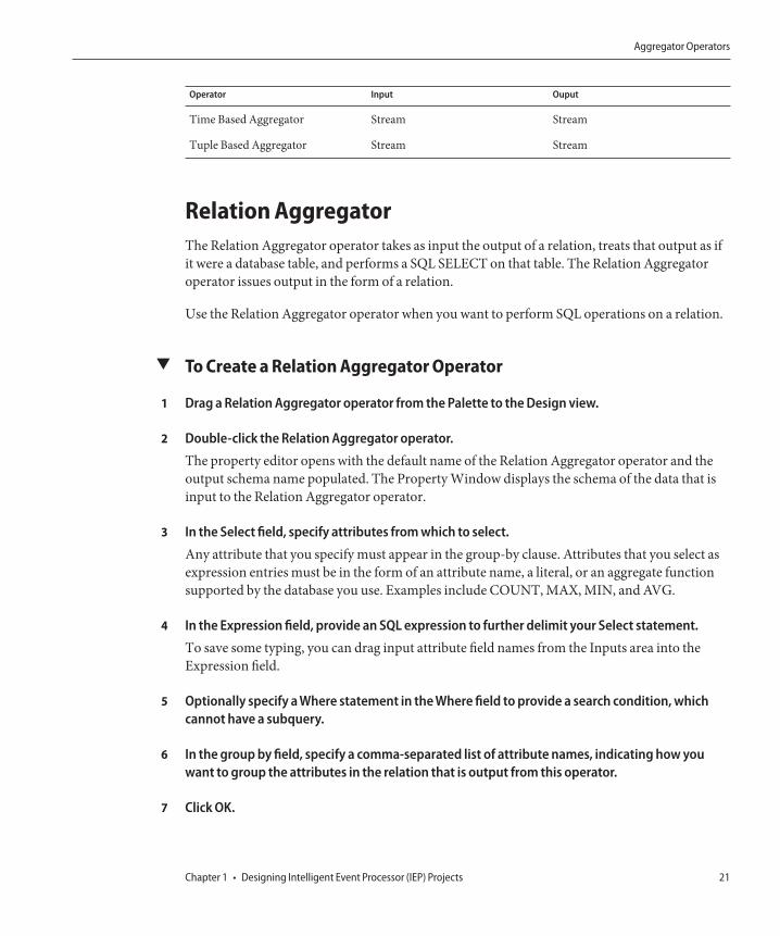
Operator Input Ouput
Time Based Aggregator Stream Stream
Tuple Based Aggregator Stream Stream
Relation AggregatorThe Relation Aggregator operator takes as input the output of a relation, treats that output as ifit were a database table, and performs a SQL SELECT on that table. The Relation Aggregatoroperator issues output in the form of a relation.
Use the Relation Aggregator operator when you want to perform SQL operations on a relation.
▼ To Create a Relation Aggregator Operator
Drag a Relation Aggregator operator from the Palette to the Design view.
Double-click the Relation Aggregator operator.
The property editor opens with the default name of the Relation Aggregator operator and theoutput schema name populated. The Property Window displays the schema of the data that isinput to the Relation Aggregator operator.
In the Select field, specify attributes from which to select.
Any attribute that you specify must appear in the group-by clause. Attributes that you select asexpression entries must be in the form of an attribute name, a literal, or an aggregate functionsupported by the database you use. Examples include COUNT, MAX, MIN, and AVG.
In the Expression field, provide an SQL expression to further delimit your Select statement.
To save some typing, you can drag input attribute field names from the Inputs area into theExpression field.
Optionally specify a Where statement in the Where field to provide a search condition, whichcannot have a subquery.
In the group by field, specify a comma-separated list of attribute names, indicating how youwant to group the attributes in the relation that is output from this operator.
Click OK.
1
2
3
4
5
6
7
Aggregator Operators
Chapter 1 • Designing Intelligent Event Processor (IEP) Projects 21

Time Based AggregatorThe Time Based Aggregator operator performs statistical analysis within a specified amount oftime that you provide as a size, which is period of time over which you can perform acalculation, or the time slot. Increment specifies the frequency of the calculation; that is, howoften you calculate the statistical analysis.
Assume that you want to calculate a stock price's 20–day moving average. You can supply a sizeof 20 in the property editor, and an increment that specifies how often you want to perform thatcalculation (for example, once a day).
Statistics that you can compute via SQL statements in the property editor of the Time BasedAggregator operator include:■ Sum■ Average■ Minimum■ Maximum■ COUNT
Use the Time Based Aggregator operator when you want to perform real-time statisticalanalysis. You can do simple or complex SQL manipulation within the time frame that youspecify, by using the Select, From and Where clauses, as indicated in the property editor.
For example, given a stream of transactions of a stock, you can compute the new stream thatholds the hourly minimum average and the maximum of the stock price.
▼ To Create a Time Based Aggregator Operator
Drag a Time Based Aggregator operator from the Palette to the Design view.
Double-click the Time Based Aggregator operator.The property editor opens.
In the Start field, enter the time to start calculating the tasks that are to be performed by theTime Based Aggregator within the process.
In the Increment field, enter the time increment for the Time Based Aggregator to perform theanalysis.
In the Size field, enter the time range for the Time Based Aggregator to perform the analysis.
In the Expression box, enter the expression for the SQL SELECT statement to specify the inputattribute upon which the SELECT is performed. Add attribute names, data types. and sizes, asapplicable.
1
2
3
4
5
6
Aggregator Operators
Intelligent Event Processor (IEP) User's Guide • February 200922

In the From box, define the input on which to perform the selection.
In the Where clause box, provide additional filtering on records.For example:
WHERE price > 30.00 AND stockDate < ’2006-01-01’ ;
In the Group by box, group a result into subsets that have matching values for one or morecolumns of the database by specifying a comma-separated list of qualified attribute names.
Click OK.
Tuple Based AggregatorThe Tuple Based Aggregator operator performs statistical analysis for a specified number ofrecords (also called tuples) that you provide as a size, and also for an increment that indicateshow often you want the operation performed.
Statistics that you can compute via SQL statements in the property editor of the Tuple BasedAggregator operator include:■ Sum■ Average■ Minimum■ Maximum■ COUNT
Use the Tuple Based Aggregator operator when you want to perform statistical analysis on aspecified number of tuples.
For example, provided a stream of stock transactions, the Tuple Based Aggregator operatorcomputes a new stream that holds the minimum, average, and maximum of the stock price ofevery 10 transactions, in which the size is 10.
▼ To Create a Tuple Based Aggregator Operator
Drag a Tuple Based Aggregator operator from the Palette to the Design view.
Double-click the Tuple Based Aggregator operator.The property editor opens.
In the Start field, enter the record in which you want the operator calculations to begin.
In the Increment field, enter how often you want the analysis performed.
7
8
9
10
1
2
3
4
Aggregator Operators
Chapter 1 • Designing Intelligent Event Processor (IEP) Projects 23

In the Expression box, enter the expression for the SQL SELECT statement that is used to specifythe input attribute upon which the SELECT is performed. You can add, delete, or moveattributes.
In the From box, define the input on which to perform the selection.
In the Where clause box, provide additional filtering on records.For example:
WHERE price > 30.00 AND stockDate < ’2006-01-01’ ;
In the Group by box, group a result into subsets that have matching values for one or morecolumns of the database by specifying a comma-separated list of qualified attribute names.
Click OK.
Correlation and Filter OperatorsCorrelation enables you to obtain data based on the relationship of two pieces of existing data.Filtering enables you to provide information to obtain a subset of data you want.
The following table lists the input and output for each operator.
Operator Input Output
Relation Map Relation Relation
Stream Projection and Filter Stream Stream
Tuple Serial Correlation Stream Stream
Relation MapThe Relation Map operator performs a select on two or more incoming relations, equivalent toa SQL join view of a minimum of one relation and additional tables and relations. The RelationMap operator can take multiple inputs.
You can use a Relation Map to join input from other operator sources, for example, from two ormore tuple based windows, or from two or more partitioned windows.
For example, with the latest two-hour window of stock transactions and the latest two-hourwindow of trader information as input, you can compute the latest two-hour window ofpossible trades by joining the trader's name with the name provided in the trader information.
5
6
7
8
9
Correlation and Filter Operators
Intelligent Event Processor (IEP) User's Guide • February 200924

▼ To Create a Relation Map Operator
Drag a Relation Map operator from the Palette to the Design view.
Connect at least two inputs to the Relation Map operator.
Double-click the Relation Map operator.
The property editor opens.
In the Expression box, enter the expression for the SQL SELECT statement. Add attribute names,data types and sizes, as applicable. Add, delete, or move attributes.
In the From field, define the input on which to perform the selection.
In the Where clause field, provide additional search criteria.
Click OK.
Stream Projection and FilterThe Stream Projection and Filter operator enables you to join a stream with multiple relationsand tables, in order to create new events or to filter existing events based on specifiedconditions.
The input to the Stream Projection and Filter operator must include one (and only one) stream.The input can also include any number of relations and tables.
The output from the Stream Projection and Filter operator is a stream.
Configuring the Stream Projection and Filter operator resembles the process of writing a SQLSELECT statement. The property editor includes a SELECT area, a FROM area, and a WHEREarea. The property editor also includes a tree structure that contains the input operators andtheir attributes.
1
2
3
4
5
6
7
Correlation and Filter Operators
Chapter 1 • Designing Intelligent Event Processor (IEP) Projects 25

In the SELECT area, you populate a table with one or more attributes. You can quickly add anexisting attribute by selecting the attribute in the tree structure and dragging it to theExpression column. You can create a new attribute by using a mathematical computation in theExpression column. In the following example, two existing attributes are multiplied to createthe new attribute.
total=Products.price*Products.tax
You can remove an attribute from the input stream by not including it in the SELECT area.
In the WHERE area, you can specify a search condition in the form of a boolean valueexpression. The boolean value expression can include the following types of predicates:comparison, between, in, like, null, quantified comparison, and exists.
One of the IEP tutorials uses the Stream Projection and Filter operator to check whether theprice of each stock transaction is significantly different from the average price of all stocktransactions during the last two minutes. The operator contains the following WHERE clause:
StockTransactions.symbol=RollingAvgPrice.symbol AND
(StockTransactions.price > 1.1 * RollingAvgPrice.price OR
Correlation and Filter Operators
Intelligent Event Processor (IEP) User's Guide • February 200926

StockTransactions.price < 0.9 * RollingAvgPrice.price)
▼ To Create a Stream Projection and Filter Operator
Drag a Stream Projection and Filter operator from the Palette to the Design view.
Connect the output of an operator that has stream output to the input of the Stream Projectionand Filter operator.
(Optional) Connect the output of one or more operators that have relation output to the input ofthe Stream Projection and Filter operator.
(Optional) Connect the output of one or more operators that have table output to the input ofthe Stream Projection and Filter operator.
Double-click the Stream Projection and Filter operator.
The property editor opens.
If you want to change the default name, then change the value in the Name field.
In the SELECT area, populate the table with one or more attributes.
By default, the SELECT area contains only one attribute row. To create additional rows, clickAdd Attribute.
You can drag and drop attributes from the tree structure into the Expression column. If you usethis approach, then the operator name is automatically added to the FROM area.
In the FROM area, specify the names of one or more input operators.
You can drag and drop operators from the tree structure into the FROM area.
You can specify an alias for a table (for example, TableInput0 t) and then use the alias in theWHERE clause. You cannot specify an alias for a stream or a relation.
If you specify more than one operator name, then separate the names with a comma (forexample, StockTransactions,RollingAvgPrice).
(Optional) In the WHERE area, specify a search condition in the form of a boolean valueexpression.
You can drag and drop operators and attributes from the tree structure into the WHERE area.
Click OK.
1
2
3
4
5
6
7
8
9
10
Correlation and Filter Operators
Chapter 1 • Designing Intelligent Event Processor (IEP) Projects 27

Tuple Serial CorrelationThe Tuple Serial Correlation operator provides correlation of sequential events; that is, theoperator uses a specification of a number of events from an existing stream to create a streamthat contains larger events.
Assume that you have a stream of transactions of a stock, and you want to compute a newstream in which each event is composed of three consecutive events from the original stream.Using the latest two stock prices as output, you can build a trading model that predicts the nextstock prices.
▼ To Create a Tuple Serial Correlation Operator
Drag a Tuple Serial Correlation operator from the Palette to the Design view.
Double-click the Tuple Serial Correlation operator.The property editor opens.
In the Increment field, enter how often you want to obtain events via the Tuple SerialCorrelation operator, based on the number of events.
In the Size field, specify the number of small consecutive events that you want to add to thelarger cumulative event.
Click OK.
Input OperatorsInput operators enable you to receive data from external sources.
External Table Polling StreamThe External Table Polling Stream operator enables you to retrieve records from an externaldatabase table at a specified interval, and to output the records as a stream. The PropertiesEditor includes a wizard that you use to specify the various properties, including the tablecolumns, the polling interval, and the number of records to retrieve.
After using the wizard, you can update the values for most of the properties from the propertyeditor. However, if you want to add or remove table columns, then you must go through thewizard again.
In the event process, you can link the output of the External Table Polling Stream operator tomore than one operator.
1
2
3
4
5
Input Operators
Intelligent Event Processor (IEP) User's Guide • February 200928

One of the properties is the JNDI name of the database resource. Before you deploy the eventprocess, ensure that the JNDI name is configured in the application server to point to a validdatabase connection. For detailed instructions on configuring JNDI names, see the applicationserver documentation.
▼ To Create an External Table Polling Stream Operator
Drag an External Table Polling Stream operator from the Palette to the Design view.
Double-click the External Table Polling Stream operator.The property editor opens.
Click Select Table.The Select External Table To Poll wizard appears.
In step 1 of the wizard, do the following:
a. Select the data source.
Note – Data sources are configured in the Databases node of the Services window.
b. Select the table from which you want to poll.
c. Click Next.
In step 2 of the wizard, do the following:
a. Select the column or columns that you want to retrieve from the table.
b. (Optional) Add a condition to the Where Clause area (for example, amount > 100).
c. Click Next.
In step 3 of the wizard, do the following:
a. The wizard displays the column or columns that you specified in step 2. Select the one ormore columns that uniquely identify each record.
Note – The operator uses this information to keep track of the last record that was retrieved.If you do not select any of the columns, then each fetch will start at the beginning of thetable.
1
2
3
4
5
6
Input Operators
Chapter 1 • Designing Intelligent Event Processor (IEP) Projects 29

b. In the Interval field and drop-down list, specify how often you want to retrieve records fromthe table.
c. In the Record Size field, specify the number of records to retrieve each time.
d. If you want to delete the records from the table after they have been fetched, then select theDelete Records check box.
Note – If you do not select the one or more columns that uniquely identify each record, thenselecting the Delete Records check box will ensure that you do not keep retrieving the samerecords.
e. In the JNDI Name field, type the JNDI name of the database resource (for example,jdbc/iepseDerbyNonXA).
f. Click Finish. The property editor displays the values that you specified.
By default, the Preserve Last Fetched Record check box is selected. This setting indicates that ifthe event process is redeployed, then the operator starts retrieving records where it left off.
If you leave the Preserve Last Fetched Record check box selected, then you must specify a tablename in the Last Fetched Record Table field. This table will be created in the IEP database, notin the external database table.
If you want the operator to go back to the beginning of the table instead, then clear the PreserveLast Fetched Record check box.
If you are retrieving records from an Oracle external database, then examine the Data Typecolumn. If a data type is not one of the supported IEP data types, then change the data type to asupported IEP data type. For example, change the DECIMAL data type to the INTEGER data type.
(Optional) In the SELECT area, modify any of the default expressions by adding a SQL function.
(Optional) Click the Documentation tab and supply notes on this component.
Click OK.
Replay StreamThe Save Stream and Replay Stream operators are intended to help you perform diagnostics.For example, you can use these operators when the output from an IEP Module project is notthe expected output.
7
8
9
10
11
Input Operators
Intelligent Event Processor (IEP) User's Guide • February 200930

You first enable the Save Stream operator to begin saving an input stream to a database table.You then use the Replay Stream operator to replay the events that the Save Stream operatorsaved to the database table.
▼ To Create a Replay Stream Operator
Drag a Replay Stream operator from the Palette to the Design view.
Connect the output of the Replay Stream operator to any operator that accepts stream input(for example, the Stream Output operator).
Double-click the Replay Stream operator.The property editor opens.
Click Select Table.The Select Table which has Stream Events wizard appears.
In step 1 of the wizard, do the following:
a. Select the data source.
Note – Data sources are configured in the Databases node of the Services window.
b. Select the table where the events are being saved.
c. Click Next.
In step 2 of the wizard, do the following:
a. Select the column or columns that you want to replay.
b. (Optional) Add a condition to the Where Clause area (for example, amount > 100).
c. Click Next.
In step 3 of the wizard, do the following:
a. Select the EMS_TIMESTAMP column.
b. In the JNDI Name field, type the JNDI name of the database resource (for example,jdbc/iepseDerbyNonXA).
c. Click Finish. The property editor displays the values that you specified.
1
2
3
4
5
6
7
Input Operators
Chapter 1 • Designing Intelligent Event Processor (IEP) Projects 31

By default, the Preserve Last Fetched Record check box is selected. This setting indicates that ifthe event process is redeployed, then the operator starts retrieving records where it left off.If you leave the Preserve Last Fetched Record check box selected, then you must specify a tablename in the Last Fetched Record Table field. This table will be created in the IEP database, notin the external database table.
If you want the operator to go back to the beginning of the table instead, then clear the PreserveLast Fetched Record check box.
(Optional) Click the Documentation tab and supply notes on this component.
Click OK.The Replay Stream operator reads events from the database table and sends the events to thenext operator.
Stream InputThe Stream Input operator enables you to convert incoming messages to a format that can beused in the event process.
In the property editor, you define a schema that consists of one or more attributes. For example,the schema could consist of two attributes: stock symbol and stock price. Each attribute has adata type, such as INTEGER or VARCHAR.
At runtime, the event process reads the incoming messages from the Normalized MessageRouter and creates a stream based on the schema that you defined.
You can connect the Stream Input operator to any operator that accepts stream input (forexample, the Time Based Window operator).
▼ To Create a Stream Input Operator
Drag a Stream Input operator from the Palette to the Design view.
Double-click the Stream Input operator.The property editor opens.
If you want to change the default name, then change the value in the Name field.
If you want to define the schema by adding attributes, then do the following:
a. For each attribute in the schema, click Add Attribute and specify the name, data type, size (ifapplicable), and scale (if applicable). You can optionally enter a comment.
8
9
10
1
2
3
4
Input Operators
Intelligent Event Processor (IEP) User's Guide • February 200932

b. To remove an attribute from the schema, select the attribute and click Delete.
c. To move an attribute up or down in the schema, select the attribute and click Move Up orMove Down.
If you want to define the schema by selecting an XML schema definition, then do the following:
a. Click Select Schema.
b. Select the element or type.
c. Click OK.
(Optional) Click the Documentation tab and supply notes on this component.
Click OK.
Table InputThe Table Input operator enables you to use a relational database table as input to the eventprocess.
You can connect the Table Input operator to any operator that accepts stream input (forexample, the Time Based Window operator).
▼ To Create a Table Input Operator
Drag a Table Input operator from the Palette to the Design view.
Double-click the Table Input operator.The property editor opens.
The Details section of the property editor displays the name of the operator and the outputschema.
In the Attributes section, you can add or delete attributes for this table input, or move theattributes up or down in order.
In the Data Type column in the Attributes section, select the appropriate data type from the listof data types.
In the Size column, you can specify the size of the data type if, for example, you specify theVARCHAR data type.
5
6
7
1
2
3
4
5
Input Operators
Chapter 1 • Designing Intelligent Event Processor (IEP) Projects 33

Click OK.
Output OperatorsOutput operators enable you to send data from an event process to an external source.
Batched Stream OutputThe Batched Stream Output operator enables you to output events in batches, rather than oneevent at a time.
Depending on the downstream JBI component, this approach can improve performance. Forexample, if you are using IEP with the File Binding Component, sending 10 events at a timemight be faster than sending one event at a time.
▼ To Create a Batched Stream Output Operator
Drag a Batched Stream Output operator from the Palette to the Design view.
Connect the input of the new Batched Stream Output component to an operator that hasstream output.
Double-click the Batched Stream Output operator.The property editor opens. Notice that the component has inherited the schema of its inputstream.
If you want to include a timestamp on the output, then select the Include Timestamp check box.
In the Batch Size field, specify the number of events in a batch.
In the Maximum Delay field and drop-down list, specify the maximum amount of time that theoperator will wait before sending a batch.For example, assume that the batch size is 10 and the maximum delay is 30 seconds. If 30seconds have passed since the previous batch was sent, and only eight events have arrived, thenthe operator sends the eight events.
(Optional) Click the Documentation tab and supply notes on this component.
Click OK.
6
1
2
3
4
5
6
7
8
Output Operators
Intelligent Event Processor (IEP) User's Guide • February 200934

Invoke StreamThe Invoke Stream operator enables you to send a stream of data from one event processdirectly to another event process. The stream does not go through the Normalized MessageRouter.
For example, you could create two event processes:
■ The first event process contains a Stream Input operator and a Stream Output operator.■ The second event process contains a Stream Input operator and an Invoke Stream operator.
You could then configure the Invoke Stream operator in the second event process to send datato the first event process.
▼ To Create an Invoke Stream Operator
Create an event process that will receive a stream of data from another event process. This eventprocess must contain a Stream Input operator.
Create an event process that will send a stream of data to the first event process. This eventprocess must contain an Invoke Stream operator.
Double-click the Invoke Stream operator in the second event process.
The property editor opens.
Click the ellipsis.
The Select Stream Input dialog box appears.
Expand the node that represents the first event process and select the Stream Input operator.
Click OK to close the Select Stream Input dialog box.
The Inputs area contains the attributes of the second event process. Drag and drop attributesfrom the Inputs area to the Expression column in the SELECT area.
(Optional) Click the Documentation tab and supply notes on this component.
Click OK to close the property editor.
Now you can deploy both event processes. When an event is sent to the stream input of thesecond event process, the Invoke Stream operator sends the event to the stream input of the firstevent process.
1
2
3
4
5
6
7
8
9
Output Operators
Chapter 1 • Designing Intelligent Event Processor (IEP) Projects 35

Relation OutputThe Relation Output operator sends out groups of tuples that reflect its input. When an eventtriggers a change in a relation result, the operator sends out changes rather than an entire resulteach time a triggering event is received.
The Relation Output operator sends out groups of tuples that reflect changes in the relationresult. Whenever an event triggers a change in the relation result, the operator sends out recordswith a tag on the end. If the tag is a plus sign (+), then the record has been added. If the tag is aminus sign (-), then the record has been deleted.
If a change occurs as a result of the triggering event such that a record changes, IEP sends adelete record matching the changed record. IEP sends an add record when there is an updatedor new version of that record. The operator only sends out change events rather than repeatedlysending the entire result.
If a triggering event enters into the event process, but the result of the final relation from thatevent does not change, then the relation output is not triggered and data is not sent.
Use the Relation Output operator to provide a summary of data that has been added or deleted.
▼ To Create a Relation Output Operator
Drag a Relation Output operator from the Palette to the Design view.
Double-click the Relation Output operator.The property editor opens.
If you want to include a timestamp on the output, then select the Include Timestamp check box.
Click OK.
Save StreamThe Save Stream and Replay Stream operators are intended to help you perform diagnostics.For example, you can use these operators when the output from an IEP Module project is notthe expected output.
You first enable the Save Stream operator to begin saving an input stream to a database table.You then use the Replay Stream operator to replay the events that the Save Stream operatorsaved to the database table.
Before you begin, you must deploy an event process that contains a Stream Input operator.
1
2
3
4
Output Operators
Intelligent Event Processor (IEP) User's Guide • February 200936

Note – If you know up front that you want to save an input stream to a database table, then youcan use the Save Stream operator at design time. The property editor enables you to configurethe same properties described in the following procedure.
▼ To Enable the Save Stream Operator Dynamically at Runtime
Start the IEP monitoring and debugging tool. For detailed information about this tool, see theOpen ESB wiki.
Run the listIEP command. You must specify the IEP service unit name as a parameter. You canfind the service unit name by going to the Services window of the IDE and expanding theServers node, the GlassFish V2 node, the JBI node, the Service Assemblies node, and theindividual service assembly node.
The command returns a list of plan names. For example:[IEP] listIEP CompositeApp1-IepModule1
test_iep
Run the listOperators command. You must specify the plan name as a parameter.
The command returns a list of the operators in the event process. For example:[IEP] listOperators test_iep
StreamInput0
StreamOutput0
Run the addSaveStream command. You must specify the following parameters: the plan name,the name of the Stream Input operator, the JNDI name of the database resource, and the nameof the database table where the input stream will be saved. You can optionally specify a booleanparameter called Is Global, which indicates whether the table and its data are kept betweendeployments. By default, the Is Global parameter is set to true.The command returns the name of the Save Stream operator that was added. For example:[IEP] addSaveStream test_iep StreamInput0 jdbc/iepseDerbyNonXA STOCKTRANSACTIONS false
The result is StreamInput0SaveStream0
The Save Stream operator begins saving the input stream to the database table. If the tablename that you specified does not exist, then the table is created.
▼ To Disable the Save Stream Operator Dynamically at Runtime
Start the IEP monitoring and debugging tool. For detailed information about this tool, see theOpen ESB wiki.
1
2
3
4
5
1
Output Operators
Chapter 1 • Designing Intelligent Event Processor (IEP) Projects 37

Run the removeSaveStream command. You must specify the following parameters: the planname and the name of the Save Stream operator. For example:[IEP] removeSaveStream test_iep StreamInput0SaveStream0
The Save Stream operator stops saving the input stream to the database table.
If the Is Global parameter of the addSaveStream command was set to true, then the table andits data are not deleted. However, if you subsequently modify the schema of the stream input(for example, by adding a column) and re-enable the Save Stream operator, then the table andits data are deleted at that time.
If the Is Global parameter of the addSaveStream command was set to false, then the table andits data are deleted.
Stream OutputThe Stream Output operator enables you to convert a stream of events into outgoing messagesthat can be sent to the Normalized Message Router and received by any JBI component.
When the WSDL document for the event processor is automatically generated, IEP uses theStream Output operator to define various WSDL elements. For example, if the Stream Outputoperator is called SuspiciousTransactions, then the WSDL document contains an operationcalled SuspiciousTransactions and a message called SuspiciousTransactions_Msg.
▼ To Create a Stream Output Operator
Drag a Stream Output operator from the Palette to the Design view.
Connect the input of the Stream Output operator to an operator that has stream output.
Double-click the Stream Output operator.
The property editor opens. Notice that the component has inherited the schema of its inputstream.
If you want to change the default name, then change the value in the Name field.
If you want to include a timestamp on the output, then select the Include Timestamp check box.
(Optional) Click the Documentation tab and supply notes on this component.
Click OK.
2
3
1
2
3
4
5
6
7
Output Operators
Intelligent Event Processor (IEP) User's Guide • February 200938
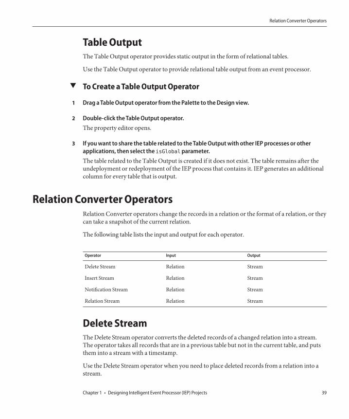
Table OutputThe Table Output operator provides static output in the form of relational tables.
Use the Table Output operator to provide relational table output from an event processor.
▼ To Create a Table Output Operator
Drag a Table Output operator from the Palette to the Design view.
Double-click the Table Output operator.The property editor opens.
If you want to share the table related to the Table Output with other IEP processes or otherapplications, then select the isGlobalparameter.The table related to the Table Output is created if it does not exist. The table remains after theundeployment or redeployment of the IEP process that contains it. IEP generates an additionalcolumn for every table that is output.
Relation Converter OperatorsRelation Converter operators change the records in a relation or the format of a relation, or theycan take a snapshot of the current relation.
The following table lists the input and output for each operator.
Operator Input Output
Delete Stream Relation Stream
Insert Stream Relation Stream
Notification Stream Relation Stream
Relation Stream Relation Stream
Delete StreamThe Delete Stream operator converts the deleted records of a changed relation into a stream.The operator takes all records that are in a previous table but not in the current table, and putsthem into a stream with a timestamp.
Use the Delete Stream operator when you need to place deleted records from a relation into astream.
1
2
3
Relation Converter Operators
Chapter 1 • Designing Intelligent Event Processor (IEP) Projects 39

▼ To Create a Delete Stream Operator
Drag a Delete Stream operator from the Palette to the Design view.
Connect the input side of the Delete Stream operator to a relation output.
Double-click the Delete Stream operator.The property editor opens.
The Details section of the property editor displays the name of the operator and the outputschema.
The Attributes section provides a picture of the current state of a stream.
Click OK.
Insert StreamThe Insert Stream operator converts a relation into a stream.
When the Insert Stream operation is triggered, all changed or new records are issued as output.
The Insert Stream operator passes new records as output. In contrast, the Relation Outputoperator issues individual records tagged with either a plus, meaning a new record, or minus,meaning a record that was issued previously but is no longer part of the relation result.
Use the Insert Stream operator when you want to pass new or changed records into the outputstream.
▼ To Create an Insert Stream Operator
Drag an Insert Stream operator from the Palette to the Design view.
Connect it to an operator with a relation output.
Double-click the Insert Stream operator.The property editor opens.
The Details section of the property editor displays the name of the operator and the outputschema.
Click OK.
1
2
3
4
5
6
1
2
3
4
5
Relation Converter Operators
Intelligent Event Processor (IEP) User's Guide • February 200940

Notification StreamThe Notification Stream operator takes a relation as input, and outputs a stream that consists ofevents whose presence is determined by a specific time interval.
Assume that the following conditions are true:
■ The time interval of the Notification Stream operator is set to 1 minute.■ An event arrives at the input relation at 2:00 in the afternoon.
If the event is still in the relation at 2:01 in the afternoon, then the event is included in the outputstream for the first time.
If the event is still in the relation at 2:02 in the afternoon, then the event is included in the outputstream for the second time.
If the event is still in the relation at 2:03 in the afternoon, then the event is included in the outputstream for the third time.
If the event is no longer in the relation at 2:04 in the afternoon, then the event is no longerincluded in the output stream.
The scenario in “Gap Window” on page 48 involves creating a relation that indicates whichmessage is missing at any point in time. You could use the Notification Stream operator tocreate an output stream of resend requests for the missing messages. Connect the Gap Windowoperator to a Notification Stream operator, configure the time interval, and then send theoutput to a Stream Output operator.
▼ To Create a Notification Stream Operator
Drag a Notification Stream operator from the Palette to the Design view.
Connect the input of the new Notification Stream component to an operator that has relationoutput.
Double-click the Notification Stream operator.The property editor opens. Notice that the component has inherited the schema of its inputrelation.
Use the Notify Every field and drop-down list to specify the time interval.
(Optional) Click the Documentation tab and supply notes on this component.
Click OK.
1
2
3
4
5
6
Relation Converter Operators
Chapter 1 • Designing Intelligent Event Processor (IEP) Projects 41
Relation StreamThe Relation Stream operator converts a relation result from an input operator into a stream. Itprovides a summary of the differences between the two consecutive tables, and places atimestamp on each event in the diff and places the result into the output stream.
Use the Relation Stream operator when you need relation result information in stream.
▼ To Create a Relation Stream Operator
Drag a Relation Stream operator from the Palette to the Design view.
If needed, double-click the Relation Stream operator to examine the Details and Attributesections.
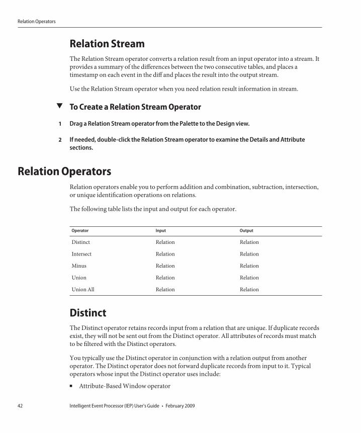
Relation OperatorsRelation operators enable you to perform addition and combination, subtraction, intersection,or unique identification operations on relations.
The following table lists the input and output for each operator.
Operator Input Output
Distinct Relation Relation
Intersect Relation Relation
Minus Relation Relation
Union Relation Relation
Union All Relation Relation
DistinctThe Distinct operator retains records input from a relation that are unique. If duplicate recordsexist, they will not be sent out from the Distinct operator. All attributes of records must matchto be filtered with the Distinct operators.
You typically use the Distinct operator in conjunction with a relation output from anotheroperator. The Distinct operator does not forward duplicate records from input to it. Typicaloperators whose input the Distinct operator uses include:
■ Attribute-Based Window operator
1
2
Relation Operators
Intelligent Event Processor (IEP) User's Guide • February 200942

■ Partitioned Window operator■ Time Based Window operator■ Tuple-Based Window operator■ Relation Map operator■ Relation Aggregator operator
When you use the Distinct operator, any records provided must be a complete duplicate,meaning that all attributes have to match for the Distinct operator to fill out all records.
The Distinct operator works with other operators. For example, you can use the Distinctoperator with a Tuple-Based Window operator to limit the number of tuples that are affected bythe operator. Or you can use the Distinct operator with the Time-Based Window operator tokeep records for only 30 seconds, but to filter out records if there are no duplicates.
▼ To Create a Distinct Operator
Drag a Distinct operator from the Palette to the Design view.
Connect an input from an operator that has a relation result.
Double-click the Distinct operator.
The property editor opens with the name of the Distinct operator and the output schema namepopulated. The property editor displays the schema of the data that is input to the Distinctoperator.
(Optional) Click the Documentation tab and supply notes on this component.
Click OK.
IntersectThe Intersect operator enables definition of relation intersection. In effect, the operator behaveslike the SQL INTERSECT command and acts as an AND operator (that is, values are selectedonly if they appear in all inputs provided to the operator).
All input schemas to the Intersect operator must be identical in format: column name and typemust match for all attributes. You cannot select a subset of columns (attributes) from the inputschemas, as you can with the SQL INTERSECT command.
1
2
3
4
5
Relation Operators
Chapter 1 • Designing Intelligent Event Processor (IEP) Projects 43

▼ To Create an Intersect Operator
Drag an Intersect operator from the Palette to the Design view.
Connect two input relations to the Intersect operator.
Double-click the Intersect operator.The property editor opens.
Examine the Details and Attributes sections.
(Optional) Click the Documentation tab and supply notes on this component.
Click OK.
MinusThe Minus operator subtracts one stream from another stream. The order of subtraction isdetermined by the order in which you connect the input relations. You cannot subtract unlikeoperator attributes. The input schemas must be identical, with identical names and types for allattributes.
Specify the operator to subtract from, then choose the expression in the Expression drop-downlist, where you can change the order for the subtraction operation. As with other operators, youcan specify multiple input streams to a minus operation, and provide filters before the Minusoperator.
▼ To Create a Minus Operator
Drag a Minus operator from the Palette to the Design view.
Connect two or more input relations to the Minus operator.
Double-click the Minus operator.The Expression field provides the order of the minus expression. This is initially determined bythe order in which the inputs were connected. You can determine this by opening the propertiespane for the Minus operator. The input ID list provides the order of the operators that theMinus operator subtracts. Next, open the properties pane for the relations feeding into theMinus operator and examine their ID.
To change the order in the Expression dialog box, choose the Order by drop-down list and a newprimary operator. The latter becomes the first operator on the Expression field. You can connect
1
2
3
4
5
6
1
2
3
4
Relation Operators
Intelligent Event Processor (IEP) User's Guide • February 200944

additional inputs to the Minus operator at a later time. You can also remove inputs. When youremove inputs, the Expression is automatically updated.
UnionThe Union operator combines elements from input relations. The Union operator captures oneof every record in every relation and provides one of every record as output, with duplicatesremoved.
All input relations must have the same schema. Relations that are output from the Unionoperator will have the same schema.
Because the Union operator does not pass through duplicates, if two different files input to itindicate size of 1, the behavior is similar to having two single streams input to a merged file.
That is, for each event a new row is added, and one subtracted. Note that if the input files areidentical (the rows are exactly the same), and the Tuple Size is also 1, then the previous output isdeleted, but nothing is added.
▼ To Create a Union Operator
Drag a Union operator from the Palette to the Design view.
Connect the input of the new Union component to two or more operators that have relationoutput.
Double-click the Union operator.The property editor opens. Notice that the component has inherited the schema of its inputrelations.
As needed, configure the following property: Name:
(Optional) Click the Documentation tab and supply notes on this component.
Click OK.
Union AllThe Union All operator combines elements from input relations, and captures one of everyrecord in every relation and provides one of every record as output, including duplicates.
All input relations must have the same schema. Relations that are output from the Union Alloperator have the same schema.
1
2
3
4
5
6
Relation Operators
Chapter 1 • Designing Intelligent Event Processor (IEP) Projects 45

You typically use the Union All operator to join data from two separate streams, such as whenyour application requires that you match data from one stream against that of another, withoutexcluding duplicate records from the output.
▼ To Create a Union All Operator
Drag a Union All operator from the Palette to the Design view.
Connect the input of the new Union All component to two or more operators that have relationoutput.
Double-click the Union All operator.The property editor opens. Notice that the component has inherited the schema of its inputrelations.
As needed, configure the following property: Name:
(Optional) Click the Documentation tab and supply notes on this component.
Click OK.
Sequence OperatorsSequence operators enable you to order events based on attributes that have sequential order.
The following table lists the input and output for each operator.
Operator Input Output
Contiguous Order Stream Stream
Gap Window Stream Relation
Contiguous OrderThe Contiguous Order operator defines a stream that consists of events selected by one or moreattributes and then placed in sequence sorted by another attribute.
Assume that you have the following scenario:
■ A server receives a stream of messages from various hardware devices.■ For each hardware device, the messages have unique IDs (1, 2, 3, 4, and so on).
1
2
3
4
5
6
Sequence Operators
Intelligent Event Processor (IEP) User's Guide • February 200946

■ Because of an unreliable network, messages may be lost or received in a different order.■ For each hardware device, you want to sort the messages by their unique ID.
You could add a Stream Input operator with the following attributes:
■ deviceID (VARCHAR)■ msgID (BIGINT)■ msg (VARCHAR)
You could then connect the Stream Input operator to a Contiguous Order operator.
In the property editor of the Contiguous Order operator, set the partition key to the deviceIDattribute. This setting divides the input stream into multiple substreams, one per device.
In the property editor of the Contiguous Order operator, set the sort value to the msgIDattribute and the start value to 1. For each substream, the Contiguous Order operator sorts themessages by their unique ID.
For example, let's say that the messages from one device arrive in the following order: 3, 2, 5, 1,7, 4, 4, 6.
When message 1 is received, the Contiguous Order operator will output messages 1, 2, and 3.When message 4 is received, the Contiguous Order operator will output messages 4 and 5.When message 6 is received, the Contiguous Order operator will output messages 6 and 7.
The Contiguous Order operator ignores duplicate events. Therefore, the output stream in thehardware device scenario contains only one instance of message 4.
Note that in the output stream, the output from the multiple substreams is interspersed.
▼ To Create a Contiguous Order Operator:
Drag a Contiguous Order operator from the Palette to the Design view.
Connect the input of the new Contiguous Order component to an operator that has streamoutput.
Double-click the Contiguous Order operator.The property editor opens. Notice that the component has inherited the schema of its inputstream.
In the Attributes area, set the Partition Key column to the attribute or attributes that you wantto use to divide the input stream into substreams.
In the Sort By drop-down list, select the attribute that you want to sort by.The attribute must have values that can be sorted sequentially.
1
2
3
4
5
Sequence Operators
Chapter 1 • Designing Intelligent Event Processor (IEP) Projects 47

In the Start field, type the attribute value that you want to start with.
(Optional) Click the Documentation tab and supply notes on this component.
Click OK.
Gap WindowThe Gap Window operator defines a relation that consists of events that are missing from theinput stream, based on an attribute that has a sequential order.
Assume that you have the following scenario:
■ A server receives a stream of messages from various hardware devices.■ For each hardware device, the messages have unique IDs (1, 2, 3, 4, and so on).■ Because of an unreliable network, messages may be lost or received in a different order.■ For each hardware device, you want to sort the messages by their unique ID.
You could add a Stream Input operator with the following attributes:
■ deviceID (VARCHAR)■ msgID (BIGINT)■ msg (VARCHAR)
You could then connect the Stream Input operator to a Gap Window operator.
In the property editor of the Gap Window operator, set the partition key to the deviceIDattribute. This setting divides the input stream into multiple substreams, one per device.
In the property editor of the Gap Window operator, set the sort value to the msgID attribute andthe start value to 1. For each substream, the Gap Window operator creates an output relationthat indicates which message is missing at any point in time.
For example, let's say that the messages from one device arrive in the following order: 3, 2, 5, 1,7, 4, 4, 6.
When message 3 is received, the Gap Window operator will output message 1. When message 1is received, the Gap Window operator will output message 4. When message 4 is received, theGap Window operator will output message 6. When message 6 is received, the Gap Windowoperator will output message 8.
Note that in the output relation, the output from the multiple relations is interspersed.
6
7
8
Sequence Operators
Intelligent Event Processor (IEP) User's Guide • February 200948

▼ To Create a Gap Window Operator:
Drag a Gap Window operator from the Palette to the Design view.
Connect the input of the new Gap Window component to an operator that has stream output.
Double-click the Gap Window operator.The property editor opens. Notice that the component has inherited the schema of its inputstream.
In the Attributes area, set the partition key to the attribute or attributes that you want to use todivide the input stream into substreams.
In the Sort By drop-down list, select the attribute that you want to sort by.The attribute must have values that can be sorted sequentially.
In the Start field, type the attribute value that you want to start with.
(Optional) Click the Documentation tab and supply notes on this component.
Click OK.
Stream Converter OperatorsStream Converter operators convert stream data formats into other formats, and can performadditional processing.
The following table lists the input and output for each operator.
Operator Input Output
Attribute Based Window Stream Relation
Partitioned Window Stream Relation
Time Based Window Stream Relation
Tuple Based Window Stream Relation
Attribute Based WindowThe Attribute Based Window operator converts an input stream to a relation based on aspecified attribute and a size that defines the range of values for the attribute.
1
2
3
4
5
6
7
8
Stream Converter Operators
Chapter 1 • Designing Intelligent Event Processor (IEP) Projects 49
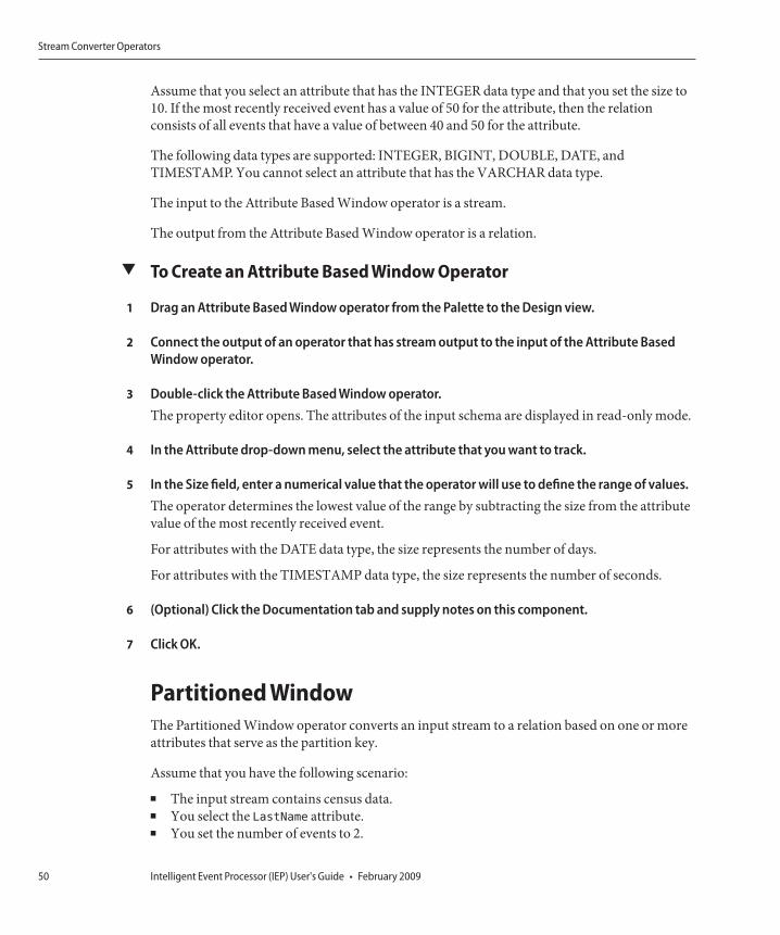
Assume that you select an attribute that has the INTEGER data type and that you set the size to10. If the most recently received event has a value of 50 for the attribute, then the relationconsists of all events that have a value of between 40 and 50 for the attribute.
The following data types are supported: INTEGER, BIGINT, DOUBLE, DATE, andTIMESTAMP. You cannot select an attribute that has the VARCHAR data type.
The input to the Attribute Based Window operator is a stream.
The output from the Attribute Based Window operator is a relation.
▼ To Create an Attribute Based Window Operator
Drag an Attribute Based Window operator from the Palette to the Design view.
Connect the output of an operator that has stream output to the input of the Attribute BasedWindow operator.
Double-click the Attribute Based Window operator.The property editor opens. The attributes of the input schema are displayed in read-only mode.
In the Attribute drop-down menu, select the attribute that you want to track.
In the Size field, enter a numerical value that the operator will use to define the range of values.The operator determines the lowest value of the range by subtracting the size from the attributevalue of the most recently received event.
For attributes with the DATE data type, the size represents the number of days.
For attributes with the TIMESTAMP data type, the size represents the number of seconds.
(Optional) Click the Documentation tab and supply notes on this component.
Click OK.
Partitioned WindowThe Partitioned Window operator converts an input stream to a relation based on one or moreattributes that serve as the partition key.
Assume that you have the following scenario:
■ The input stream contains census data.■ You select the LastName attribute.■ You set the number of events to 2.
1
2
3
4
5
6
7
Stream Converter Operators
Intelligent Event Processor (IEP) User's Guide • February 200950

Each relation will consist of the last two events that contain the LastName attribute.
The input to the Partitioned Window operator is a stream.
The output from the Partitioned Window operator is a relation.
▼ To Create a Partitioned Window Operator
Drag a Partitioned Window operator from the Palette to the Design View.
Connect the output of an operator that has stream output to the input of the PartitionedWindow operator.
Double-click the Partitioned Window operator.The property editor opens. The attributes of the input schema are displayed in read-only mode.
In the Size field, specify the number of events.
In the Partition Key column, select one or more attributes.
(Optional) Click the Documentation tab and supply notes on this component.
Click OK.
Time Based WindowThe Time Based Window operator converts an input stream to a relation based on a specifiedperiod of time.
Assume that you set the period of time to five seconds. Each relation will consist of all eventsthat arrived in the last five seconds.
The input to the Time Based Window operator is a stream.
The output from the Time Based Window operator is a relation.
You can combine the Time Based Window operator with a subsequent Relation Outputoperator to provide a timestamp record for the records retained.
▼ To Create a Time Based Window Operator
Drag a Time Based Window operator from the Palette to the Design view.
Connect the output of an operator that has stream output to the input of the Time BasedWindow operator.
1
2
3
4
5
6
7
1
2
Stream Converter Operators
Chapter 1 • Designing Intelligent Event Processor (IEP) Projects 51

Double-click the Time Based Window operator.The property editor opens. The attributes of the input schema are displayed in read-only mode.
In the Size field and drop-down menu, specify the period of time.
(Optional) Click the Documentation tab and supply notes on this component.
Click OK.
Tuple Based WindowThe Tuple Based Window operator converts an input stream to a relation based on a specifiednumber of events.
Assume that you set the number of events to two. Each relation will consist of the most recenttwo events.
The input to the Tuple Based Window operator is a stream.
The output from the Tuple Based Window operator is a relation.
▼ To Create a Tuple Based Window Operator
Drag a Tuple Based Window operator from the Palette to the Design view.
Connect the output of an operator that has stream output to the input of the Tuple BasedWindow operator.
Double-click the Tuple Based Window operator.The property editor opens. The attributes of the input schema are displayed in read-only mode.
In the Size field, specify the number of events.
(Optional) Click the Documentation tab and supply notes on this component.
Click OK.
3
4
5
6
1
2
3
4
5
6
Stream Converter Operators
Intelligent Event Processor (IEP) User's Guide • February 200952

WSDL Documents in IEP Module ProjectsWhen you save an IEP Module project, IEP generates a Web Services Description Language(WSDL) document for each event processor.
The WSDL documents contain the endpoints for the event processors.
Caution – Do not edit any section of the generated WSDL other than the following sections:■ HTTP SOAP binding and service generation for input■ File binding and service generation for output
IEP generates a WSDL document according to specific rules based on the XML Schema (theXSD) that are important to understand. These rules are provided as reference and to enable youto change specific binding components and service engines that can be changed.
The name of the WSDL document is derived from the name of the event processor. Forexample, if the event processor is called insiderTrade.iep, then the WSDL document is calledinsiderTrade.wsdl.
Note – If you subsequently rename the event processor, IEP does not refactor the name of theWSDL document.
The target namespace is a convention of an XML Schema that enables the WSDL document torefer to itself.
In the process of representing the event process in the WSDL document, the name of your eventprocess is concatenated with the string _iep to form the target namespace. For example, if thename of the event process is MyEventProcessor, then the target namespace of the WSDL isMyEventProcessor_iep.
<definitions targetNamespace="MyEventProcessor_iep"
xmlns:tns="MyEventProcessor_iep"xmlns:typens="MyEventProcessor_iep"xmlns:defns="MyEventProcessor_iep"xmlns:xsd="http://www.w3.org/2001/XMLSchema"xmlns:soap="http://schemas.xmlsoap.org/wsdl/soap/"xmlns:file="http://schemas.sun.com/jbi/wsdl-extensions/file/"xmlns="http://schemas.xmlsoap.org/wsdl/">
Data Types in the WSDL DocumentThe WSDL document defines XSD types (data types). IEP data types, as observable and editablefrom the property editor for a specific operator, have their counterparts in XSD data types.
WSDL Documents in IEP Module Projects
Chapter 1 • Designing Intelligent Event Processor (IEP) Projects 53

For each operator, IEP generates two XSD elements: a regular message object and a batchmessage object.
Each XSD element contains the following:■ Operator name■ Attribute name for each attribute in the attribute list■ XSD data type
Attributes have specific data types and have their equivalent representation in the XSD.
IEP Data Type XSD Data Type
INTEGER int
BIGINT long
DOUBLE double
VARCHAR string
DATE date
TIMESTAMP dateTime
The following types are based on a simple event process that contains a Stream Input operatorand a Stream Output operator.
<types>
<xsd:schema targetNamespace="MyEventProcessor_iep"xmlns:xsd="http://www.w3.org/2001/XMLSchema">
<xsd:element name="MyStreamInput_MsgObj"><xsd:complexType>
<xsd:sequence>
<xsd:element name="AttrInteger" type="xsd:int"/><xsd:element name="AttrBigInt" type="xsd:long"/><xsd:element name="AttrDouble" type="xsd:double"/><xsd:element name="AttrVarchar" type="xsd:string"/><xsd:element name="AttrDate" type="xsd:date"/><xsd:element name="AttrTimestamp" type="xsd:dateTime"/>
</xsd:sequence>
</xsd:complexType>
</xsd:element>
<xsd:element name="MyStreamInputBatch_MsgObj"><xsd:complexType>
<xsd:sequence>
<xsd:element name="MyStreamInput_MsgObj" minOccurs="0"maxOccurs="unbounded">
<xsd:complexType>
WSDL Documents in IEP Module Projects
Intelligent Event Processor (IEP) User's Guide • February 200954

<xsd:sequence>
<xsd:element name="AttrInteger" type="xsd:int"/><xsd:element name="AttrBigInt" type="xsd:long"/><xsd:element name="AttrDouble" type="xsd:double"/><xsd:element name="AttrVarchar" type="xsd:string"/><xsd:element name="AttrDate" type="xsd:date"/><xsd:element name="AttrTimestamp" type="xsd:dateTime"/>
</xsd:sequence>
</xsd:complexType>
</xsd:element>
</xsd:sequence>
</xsd:complexType>
</xsd:element>
<xsd:element name="StreamOutput0_MsgObj"><xsd:complexType>
<xsd:sequence>
<xsd:element name="AttrInteger" type="xsd:int"/><xsd:element name="AttrBigInt" type="xsd:long"/><xsd:element name="AttrDouble" type="xsd:double"/><xsd:element name="AttrVarchar" type="xsd:string"/><xsd:element name="AttrDate" type="xsd:date"/><xsd:element name="AttrTimestamp" type="xsd:dateTime"/>
</xsd:sequence>
</xsd:complexType>
</xsd:element>
</xsd:schema>
</types>
Message Objects in the WSDL DocumentThe WSDL document contains two types of message objects:
■ Regular message object■ Batch message object
IEP uses the regular message object when you are sending in one message at a time. A batchmessage object is useful when you want to send in multiple messages.
<message name="MyStreamInput_Msg"><part name="input" element="typens:MyStreamInput_MsgObj"/>
</message>
<message name="MyStreamInputBatch_Msg"><part name="input" element="typens:MyStreamInputBatch_MsgObj"/>
</message>
<message name="StreamOutput0_Msg"><part name="output" element="typens:StreamOutput0_MsgObj"/>
</message>
WSDL Documents in IEP Module Projects
Chapter 1 • Designing Intelligent Event Processor (IEP) Projects 55

If one of the messages in the batch message group fails to be processed appropriately in the IEP,others will fail as well.
With a single message object, message failure is on a one-by-one basis.
Bindings and Services in the WSDL DocumentBy default, the WSDL documents that are automatically generated in an IEP Module projectinclude concrete information (bindings and services).
You can configure IEP to generate abstract WSDL documents instead.
Generating Concrete WSDL DocumentsBy default, the WSDL documents that are automatically generated in an IEP Module projectinclude concrete information (bindings and services).
If the event processor has a Stream Input operator, then the WSDL document contains aSOAP-based binding and service.
If the event processor has a Stream Output operator, a Batched Stream Output operator, or aRelation Output operator, then the WSDL document contains a file-based binding and service.
The following example shows a SOAP-based binding and service, followed by a file-basedbinding and service.
<binding name="InputBinding" type="defns:InputPt"><soap:binding style="document" transport="http://schemas.xmlsoap.org/soap/http"/><operation name="MyStreamInput">
<soap:operation soapAction="MyStreamInput"/><input>
<soap:body use="literal"/></input>
</operation>
<operation name="MyStreamInputBatch"><soap:operation soapAction="MyStreamInputBatch"/><input>
<soap:body use="literal"/></input>
</operation>
</binding>
<service name="InputService"><port name="InputPort" binding="tns:InputBinding">
<soap:address location="http://localhost:12100/service/newEventProcessor_iep"/></port>
WSDL Documents in IEP Module Projects
Intelligent Event Processor (IEP) User's Guide • February 200956

</service>
<binding name="OutputBinding_StreamOutput0" type="defns:OutputPt_StreamOutput0"><file:binding/>
<operation name="StreamOutput0"><file:operation/>
<input>
<file:message fileName="StreamOutput0.txt"fileNameIsPattern="false"addEOL="false"multipleRecordsPerFile="true"use="literal"/>
</input>
</operation>
</binding>
<service name="OutputService_StreamOutput0"><port name="OutputPort_StreamOutput0" binding="tns:OutputBinding_StreamOutput0">
<file:address fileDirectory="C:/temp/newEventProcessor_iep"/></port>
</service>
You might need to manually update the default settings for any binding and service. Forexample, the default file directory is a Windows path, which would not work correctly on aUNIX system.
For detailed information about the binding and service configuration, see the documentationfor the HTTP Binding Component and the File Binding Component.
Note – If you manually update the WSDL document and then save the IEP Module project again,the changes that you made to the WSDL document are overwritten.
Generating Abstract WSDL DocumentsYou can configure IEP to generate abstract WSDL documents by editing a flag in the IEPproject properties file. The bindings and services are not included.
With this approach, you can define the bindings and services by using the CompositeApplication Service Assembly (CASA) Editor.
WSDL Documents in IEP Module Projects
Chapter 1 • Designing Intelligent Event Processor (IEP) Projects 57

Caution – If you use the CASA Editor, do not clone the IEP WSDL document to customize itsgenerated bindings and services. Updates to the generated WSDL documents will not beupdated after the cloning. Over time, the cloned and edited WSDL document deployed for thebindings will become inconsistent with the WSDL document deployed for the IEP ServiceEngine.
▼ To Generate Abstract WSDL Documents
Go to the location of the IEP Module project and open the project.properties file.
Change the value of the always.generate.abstract.wsdl flag to true.
Save the project.properties file.
Understanding the IEP DatabaseIEP uses a set of database tables to maintain information about the IEP Service Engine anddeployed event processes. You can connect to the database through NetBeans, and then viewthe tables and their content through NetBeans windows. To view the IEP database tables, clickthe Services window of the NetBeans IDE. Expand the Databases node, the connection node,and the Tables node.
1
2
3
Understanding the IEP Database
Intelligent Event Processor (IEP) User's Guide • February 200958

To view the contents of an IEP database table, right-click the table node and choose View Data.The SQL Editor appears and displays the appropriate SQL SELECT statement, which isperformed on the table. The results of the query appear near the bottom of the SQL Editor.
The following image shows the contents of the EMS_PLAN table.
Understanding the IEP Database
Chapter 1 • Designing Intelligent Event Processor (IEP) Projects 59

You can use any of the following database servers for the IEP database:■ MySQL ES 5.1.32■ Java DB (bundled with GlassFish)■ Oracle Database 11g■ Oracle Database 10g■ Oracle 9i Database
Configuring the IEP Database to Use OracleBy default, the IEP database is configured to use Java DB. Java DB is Sun's supporteddistribution of the open source Apache Derby database. After installation, you can configurethe IEP database to use Oracle instead.
The first task is to create an IEP user in the Oracle database. You can run a provided SQL scriptthat creates the IEP user and grants the appropriate privileges. The default version of the scriptcontains the following SQL statements:
CREATE TABLESPACE "IEPSEDB_DB"DATAFILE
’IEPSEDB_DB1.dat’ SIZE 2000M,
’IEPSEDB_DB2.dat’ SIZE 2000M;
CREATE USER IEPSEDB IDENTIFIED BY IEPSEDB
DEFAULT TABLESPACE IEPSEDB_DB
QUOTA UNLIMITED ON IEPSEDB_DB
TEMPORARY TABLESPACE temp
QUOTA 0M ON system;
GRANT CONNECT TO IEPSEDB;
Understanding the IEP Database
Intelligent Event Processor (IEP) User's Guide • February 200960

GRANT RESOURCE TO IEPSEDB;
GRANT CREATE VIEW TO IEPSEDB;
grant select on sys.dba_pending_transactions to IEPSEDB;
grant select on sys.pending_trans$ to IEPSEDB;
grant select on sys.dba_2pc_pending to IEPSEDB;
grant execute on sys.dbms_system to IEPSEDB;
grant select on SYS.dba_2pc_neighbors to IEPSEDB;
grant force any transaction to IEPSEDB;
You need to create two sets of connection pools and JDBC resources. A connection pool is agroup of reusable connections for a particular database. The server maintains a pool of availableconnections to increase performance. A JDBC resource provides applications with a means ofconnecting to a database. Additional configuration of the service engine is also required.
To configure the IEP Service Engine to use Oracle, perform the following steps:
■ “To Create the IEP User in the Oracle Database” on page 61■ “To Install the Oracle Database Driver in the Application Server” on page 62■ “To Create the Non-XA Connection Pool” on page 62■ “To Create the Non-XA JDBC Resource” on page 63■ “To Create the XA Connection Pool” on page 63■ “To Create the XA JDBC Resource” on page 64■ “To Enable Automatic Recovery of XA Transactions” on page 65■ “To Configure the IEP Service Engine to Use the JDBC Resources” on page 65■ “To Restart the IEP Service Engine and Create the Database Tables” on page 65
▼ To Create the IEP User in the Oracle Database
In a web browser, enter the following URL: http://wiki.open-esb.java.net/Wiki.jsp?page=HowToRunIEPOnOracle.
Download the create_iepse_user.sql script.
Open the create_iepse_user.sql script and review the instructions.
The names of the tablespace, data files, user, and password include the string IEPSEDB. If youwant to change this string to a different string, then replace all occurrences of IEPSEDBwith thenew string.
Connect to the Oracle database as a user with the SYSDBAprivilege.
Run the create_iepse_user.sql script against the database.
1
2
3
4
5
6
Understanding the IEP Database
Chapter 1 • Designing Intelligent Event Processor (IEP) Projects 61

▼ To Install the Oracle Database Driver in the Application Server
Go to the computer where the application server is installed.
Copy and paste the Oracle database driver (for example, ojdbc14.jar) to theglassfish-home/libdirectory.
Restart the application server.
▼ To Create the Non-XA Connection Pool
Log in to the GlassFish Admin Console.
In the left navigation panel, expand Resources and JDBC, and then select Connection Pools.
Click New.The New JDBC Connection Pool page appears.
Do the following:
a. In the Name field, specify a name for the non-XA connection pool (for example,iepseOraclePoolNonXA).
b. In the Resource Type field, select javax.sql.DataSource.
c. In the Database Vendor field, select Oracle.
d. Click Next.
Scroll down to the Additional Properties table, and then do the following:
a. In the User row, enter the user name of the IEP user (for example, IEPSEDB).
b. In the Password row, enter the password of the IEP user (for example, IEPSEDB).
c. In the URL row, enter the string for connecting to the database (for example,jdbc:oracle:thin:@myserver:1521:orcl).
Click Finish.The connection pool is created.
Click the connection pool that you just created.The Edit Connection Pool page appears.
1
2
3
1
2
3
4
5
6
7
Understanding the IEP Database
Intelligent Event Processor (IEP) User's Guide • February 200962
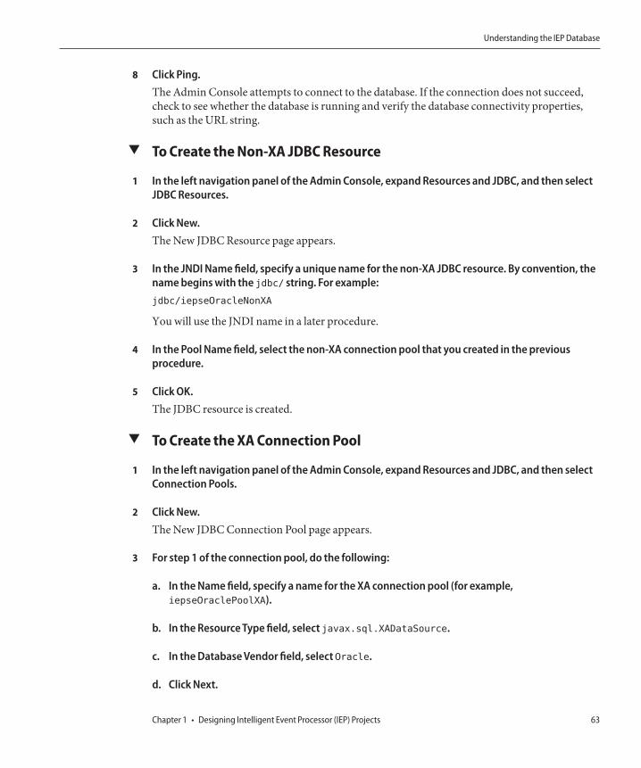
Click Ping.The Admin Console attempts to connect to the database. If the connection does not succeed,check to see whether the database is running and verify the database connectivity properties,such as the URL string.
▼ To Create the Non-XA JDBC Resource
In the left navigation panel of the Admin Console, expand Resources and JDBC, and then selectJDBC Resources.
Click New.The New JDBC Resource page appears.
In the JNDI Name field, specify a unique name for the non-XA JDBC resource. By convention, thename begins with the jdbc/ string. For example:jdbc/iepseOracleNonXA
You will use the JNDI name in a later procedure.
In the Pool Name field, select the non-XA connection pool that you created in the previousprocedure.
Click OK.The JDBC resource is created.
▼ To Create the XA Connection Pool
In the left navigation panel of the Admin Console, expand Resources and JDBC, and then selectConnection Pools.
Click New.The New JDBC Connection Pool page appears.
For step 1 of the connection pool, do the following:
a. In the Name field, specify a name for the XA connection pool (for example,iepseOraclePoolXA).
b. In the Resource Type field, select javax.sql.XADataSource.
c. In the Database Vendor field, select Oracle.
d. Click Next.
8
1
2
3
4
5
1
2
3
Understanding the IEP Database
Chapter 1 • Designing Intelligent Event Processor (IEP) Projects 63

For step 2 of the connection pool, do the following:
a. Scroll down to the Connection Validation section.
b. Select the Enabled check box that appears to the right of the Allow Non Component Callerslabel.
c. Scroll down to the Additional Properties table.
d. In the User row, enter the user name of the IEP user (for example, IEPSEDB).
e. In the Password row, enter the password of the IEP user (for example, IEPSEDB).
f. In the URL row, enter the string for connecting to the database (for example,jdbc:oracle:thin:@myserver:1521:orcl).
Click Finish.The connection pool is created.
Click the connection pool that you just created.The Edit Connection Pool page appears.
Click Ping.The Admin Console attempts to connect to the database. If the connection does not succeed,check to see whether the database is running, and verify the connectivity parameters, such asthe URL string.
▼ To Create the XA JDBC Resource
In the left navigation panel of the Admin Console, expand Resources and JDBC, and then selectJDBC Resources.
Click New.The New JDBC Resource page appears.
In the JNDI Name field, specify a unique name for the XA JDBC resource. By convention, thename begins with the jdbc/ string. For example:jdbc/iepseOracleXA
You use the JNDI name in a later procedure.
In the Pool Name drop-down menu, select the XA connection pool that you created.
4
5
6
7
1
2
3
4
Understanding the IEP Database
Intelligent Event Processor (IEP) User's Guide • February 200964

Click OK.The JDBC resource is created.
▼ To Enable Automatic Recovery of XA Transactions
In the left navigation panel of the Admin Console, expand Configuration and then selectTransaction Service.
Select the Enabled check box that appears to the right of the On Restart label.
Click Save.
▼ To Configure the IEP Service Engine to Use the JDBC Resources
Log in to the NetBeans IDE.
In the Services window, expand Servers > GlassFish V2 > JBI > Service Engines.
If the IEP Service Engine is not started, right-click sun-iep-engine and select Start.
Right-click sun-iep-engine and select Properties.The Properties dialog box appears.
In the Non XA Data Source Name property, enter the non-XA JDBC resource that you created (forexample, jdbc/iepseOracleNonXA).
In the XA Data Source Name property, enter the XA JDBC resource that you created (for example,jdbc/iepseOracleXA).
In the Database Schema Name property, enter the user name of the IEP user (for example,IEPSEDB).In an Oracle database, the database schema name is identical to the user name.
Click OK.
▼ To Restart the IEP Service Engine and Create the Database TablesWhen you restart the IEP Service Engine, the database tables are automatically created in thedatabase you specified through the connection pools and runtime properties.
If any Composite Application projects that contain event processes are currently deployed,undeploy the projects.
5
1
2
3
1
2
3
4
5
6
7
8
1
Understanding the IEP Database
Chapter 1 • Designing Intelligent Event Processor (IEP) Projects 65

In the Services window, expand Servers > GlassFish V2 > JBI > Service Engines.
Right-click sun-iep-engine and select Stop.
Right-click sun-iep-engine and select Start.
If you undeployed any Composite Application projects, you can now redeploy the projects.
Configuring the IEP Database to Use MySQLBy default, the IEP database is configured to use Java DB. Java DB is Sun's supporteddistribution of the open source Apache Derby database. After installation, you can configurethe IEP database to use MySQL instead.
The first task is to create an IEP user in the MySQL database and install the MySQL driver. Youalso need to create two sets of connection pools and JDBC resources. A connection pool is agroup of reusable connections for a particular database. The server maintains a pool of availableconnections to increase performance. A JDBC resource provides applications with a means ofconnecting to a database. Additional configuration of the service engine is also required.
To configure the IEP Service Engine to use MySQL, perform the following steps:
■ “To Create the IEP User in the MySQL Database” on page 66■ “To Install the MySQL Database Driver in the Application Server” on page 67■ “To Create the Non-XA Connection Pool” on page 67■ “To Create the Non-XA JDBC Resource” on page 68■ “To Create the XA Connection Pool” on page 68■ “To Create the XA JDBC Resource” on page 69■ “To Enable Automatic Recovery of XA Transactions” on page 70■ “To Configure the IEP Service Engine to Use the JDBC Resources” on page 70■ “To Restart the IEP Service Engine and Create the Database Tables” on page 71
▼ To Create the IEP User in the MySQL Database
Connect to the MySQL database as a user as root.
Run the following statements against the database:create user username@hostname identified by ’password’;create database database-name;grant all on database-name.* to username@hostname;
2
3
4
5
1
2
Understanding the IEP Database
Intelligent Event Processor (IEP) User's Guide • February 200966

Note – In the default Java DB database, the database schema name, username, and password areall IEPSEDB. You do not need to use these values.
▼ To Install the MySQL Database Driver in the Application Server
Go to the computer where the application server is installed.
Copy and paste the MySQL database driver (mysql-connector-java-5.1.6-bin.jar) to theglassfish-home/libdirectory.
Restart the application server.
▼ To Create the Non-XA Connection Pool
Log in to the GlassFish Admin Console.
In the left navigation panel, expand Resources and JDBC, and then select Connection Pools.
Click New.The New JDBC Connection Pool page appears.
Do the following:
a. In the Name field, specify a name for the non-XA connection pool (for example,iepseMySqlPoolNonXA).
b. In the Resource Type field, select javax.sql.DataSource orjavax.sql.ConnectionPoolDataSource.
c. In the Database Vendor field, select MySQL.
d. Click Next.
Scroll down to the Additional Properties table, and enter the following values:
■ port – The port number for the database. By default, MySQL uses 3306.■ databaseName – The name of the database schema.■ serverName – The name of the server on which the database is located.■ user – The login ID of the IEP user (for example, IEPSEDB).■ password – The password of the IEP user (for example, IEPSEDB).
1
2
3
1
2
3
4
5
Understanding the IEP Database
Chapter 1 • Designing Intelligent Event Processor (IEP) Projects 67

■ url – The string for connecting to the database (for example,jdbc:mysql://myserver:3306/IEPSEDB).
Click Finish.The connection pool is created.
Click the connection pool that you just created.The Edit Connection Pool page appears.
Click Ping.The Admin Console attempts to connect to the database. If the connection does not succeed,check to see whether the database is running and verify the database connectivity properties,such as the URL string.
▼ To Create the Non-XA JDBC Resource
In the left navigation panel of the Admin Console, expand Resources and JDBC, and then selectJDBC Resources.
Click New.The New JDBC Resource page appears.
In the JNDI Name field, specify a unique name for the non-XA JDBC resource. By convention, thename begins with the jdbc/ string. For example:jdbc/iepseMySqlNonXA
You will use the JNDI name in a later procedure.
In the Pool Name field, select the non-XA connection pool that you created in the previousprocedure.
Click OK.The JDBC resource is created.
▼ To Create the XA Connection Pool
In the left navigation panel of the Admin Console, expand Resources and JDBC, and then selectConnection Pools.
Click New.The New JDBC Connection Pool page appears.
6
7
8
1
2
3
4
5
1
2
Understanding the IEP Database
Intelligent Event Processor (IEP) User's Guide • February 200968

Do the following:
a. In the Name field, specify a name for the XA connection pool (for example,iepseMuyMySqlPoolXA).
b. In the Resource Type field, select javax.sql.XADataSource.
c. In the Database Vendor field, select MySQL.
d. Click Next.
Scroll down to the Connection Validation section, and select the Enabled check box that appearsto the right of the Allow Non Component Callers label.
Scroll down to the Additional Properties table, and enter the following values:
■ port – The port number for the database. By default, MySQL uses 3306.■ databaseName – The name of the database schema.■ serverName – The name of the server on which the database is located.■ user – The login ID of the IEP user (for example, IEPSEDB).■ password – The password of the IEP user (for example, IEPSEDB).■ url – The string for connecting to the database (for example,
jdbc:mysql://myserver:3306/IEPSEDB).
Click Finish.The connection pool is created.
Click the connection pool that you just created.The Edit Connection Pool page appears.
Click Ping.The Admin Console attempts to connect to the database. If the connection does not succeed,check to see whether the database is running, and verify the connectivity parameters, such asthe URL string.
▼ To Create the XA JDBC Resource
In the left navigation panel of the Admin Console, expand Resources and JDBC, and then selectJDBC Resources.
Click New.The New JDBC Resource page appears.
3
4
5
6
7
8
1
2
Understanding the IEP Database
Chapter 1 • Designing Intelligent Event Processor (IEP) Projects 69

In the JNDI Name field, specify a unique name for the XA JDBC resource. By convention, thename begins with the jdbc/ string. For example:
jdbc/iepseMySqlXA
You use the JNDI name in a later procedure.
In the Pool Name drop-down menu, select the XA connection pool that you created.
Click OK.
The JDBC resource is created.
▼ To Enable Automatic Recovery of XA Transactions
In the left navigation panel of the Admin Console, expand Configuration and then selectTransaction Service.
Select the Enabled check box that appears to the right of the On Restart label.
Click Save.
▼ To Configure the IEP Service Engine to Use the JDBC Resources
Log in to the NetBeans IDE.
In the Services window, expand Servers > GlassFish V2 > JBI > Service Engines.
If the IEP Service Engine is not started, right-click sun-iep-engine and select Start.
Right-click sun-iep-engine and select Properties.
The Properties dialog box appears.
In the Non XA Data Source Name property, enter the non-XA JDBC resource that you created (forexample, jdbc/iepseMySqlNonXA).
In the XA Data Source Name property, enter the XA JDBC resource that you created (for example,jdbc/iepseMySQLXA).
In the Database Schema Name property, enter the name of the MySQL schema for the IEPdatabase.
Click OK.
3
4
5
1
2
3
1
2
3
4
5
6
7
8
Understanding the IEP Database
Intelligent Event Processor (IEP) User's Guide • February 200970

▼ To Restart the IEP Service Engine and Create the Database TablesWhen you restart the IEP Service Engine, the database tables are automatically created in thedatabase you specified through the connection pools and runtime properties.
If any Composite Application projects that contain event processes are currently deployed,undeploy the projects.
In the Services window, expand Servers > GlassFish V2 > JBI > Service Engines.
Right-click sun-iep-engine and select Stop.
Right-click sun-iep-engine and select Start.
If you undeployed any Composite Application projects, you can now redeploy the projects.
IEP Service Engine-Specific Database TablesWhen you start the IEP Service Engine for the first time, the following tables are created in theIEP database. These tables apply to the IEP Service Engine as a whole.
Caution – Do not delete or alter these tables.
EMS_PLAN TableThe EMS_PLAN table maintains information about the event processes that are deployed to theIEP Service Engine. The EMS_PLAN table contains the following columns:■ ID. An integer that uniquely identifies the event process.■ INSTANCE_ID. A value that represents the event process.■ NAME. The name of the event process.■ CONTENT. The XML content of the event process. The value is displayed in binary format.■ LAST_ACTIVATION. The last time the event process was started.■ STATUS. The status of the event process definition. The valid values are started, stopped,
deployed, and undeployed.■ ENGINE_ID. The ID of the cluster node that is running the event process. If you are not
running IEP in cluster mode, then the value is stand-alone.
EMS_OUTPUT TableThe EMS_OUTPUT table maintains information for event processes that have a Table Outputoperator. The EMS_OUTPUT table contains the following columns:
1
2
3
4
5
Understanding the IEP Database
Chapter 1 • Designing Intelligent Event Processor (IEP) Projects 71

■ PLAN_INSTANCE_ID. The instance ID of the event process that has the Table Outputoperator.
■ OUTPUT_NAME. The name of the table.■ OUTPUT_DESCRIPTION. The description of the table.■ LAST_UPDATED. The last time the output table was updated.
EMS_ENGINE TableThe EMS_ENGINE table is used when you are running IEP in cluster mode. TheEMS_ENGINE table contains the following columns:
■ ID. A value that uniquely identifies the IEP instance (instance1, instance2, and so on). Ifyou are not running IEP in cluster mode, then the value is stand-alone.
■ INSTANCE_LOCATION. The IP address of the computer where the IEP instance isrunning.
■ LEASE_EXPIRATION. A timestamp that the cluster nodes use to determine which IEPinstance is active.
EMS_TOKEN TableThe EMS_TOKEN table is used when you are running IEP in cluster mode. The EMS_TOKENtable contains the following columns:
■ ID. The unique identifier of a token that can be acquired and released by cluster nodes.■ NAME. The name of a token that can be acquired and released by cluster nodes.
Event Process-Specific Database TablesWhen you deploy an event process, the following tables are created in the IEP database. If youundeploy the event process, then the tables are deleted.
Caution – Do not delete or alter these tables.
EMS_PROCESSING_STATE_N TablesThe EMS_PROCESSING_STATE_N tables are used by the IEP Service Engine to maintainexecution state for an event process. The EMS_PROCESSING_STATE_N tables contain thefollowing columns:
■ PROCESSING_STATE. The execution state of the event process. The value is displayed inbinary format.
Understanding the IEP Database
Intelligent Event Processor (IEP) User's Guide • February 200972

■ PREV_TIMESTAMP_TO_CHECK. A timestamp that the IEP Service Engine uses tomaintain execution state for the event process.
■ PREV_TIMESTAMP_TO_PROCESS. A timestamp that the IEP Service Engine uses tomaintain execution state for the event process.
EMS_TABLE_USAGE_N TablesThe EMS_TABLE_USAGE_N tables are used in garbage collection. TheEMS_TABLE_USAGE_N tables contain the following columns:
■ TABLE_NAME. The name of a table.■ USER_ID. The ID of the operator that is using the table.■ EMS_TIMESTAMP. A timestamp that is used in garbage collection.
Operator-Specific Database TablesIn the IEP Service Engine, one or more tables are created per operator. These tables are specificto operator behavior and functionality.
Caution – Do not delete or alter these tables.
The following table names illustrate how the names are formatted.
■ Q_0_O0■ Q_0_O1■ Q_1_O0■ Q_1_O1
The first character of the table name is always Q.
The character after the first underscore is the ID of the event processor in the EMS_PLAN table.
The characters after the second underscore are the ID of the operator. You can view theoperator ID in the IEP design view by selecting the operator and displaying the Propertieswindow.
Understanding the IEP Database
Chapter 1 • Designing Intelligent Event Processor (IEP) Projects 73

The operator ID is automatically generated. You cannot change the ID.
Configuring Message Reliability in an IEP Module ProjectThe IEP Service Engine receives messages from and sends messages to other Java BusinessIntegration (JBI) components. You can configure an IEP Module project for reliability in thesemessage exchanges. If the system crashes and is subsequently restarted, message loss andmessage duplication do not occur.
This feature is supported for any JBI component that supports XA transactions.
You must follow the JBI component's procedure for configuring XA transactions.
Assume that you create an IEP Module project that receives messages from the JMS BindingComponent and sends messages to the JMS Binding Component. To configure messagereliability, set the transaction attribute of the JMS operation element to XATransaction.
The following example shows an input binding in a WSDL document. The transactionattribute is set to XATransaction.
<binding name="InputBinding"type="defns:InputPt">
<jms:binding></jms:binding>
<operation name="StreamInput0"><jms:operation destination="ext_client_publish_IEPCrashAndRecoveryNoBP"
destinationType="Queue"transaction="XATransaction"
maxConcurrentConsumers="32"></jms:operation>
<input>
<jms:message textPart="input"messageType="TextMessage">
</jms:message>
</input>
</operation>
</binding>
Configuring Message Reliability in an IEP Module Project
Intelligent Event Processor (IEP) User's Guide • February 200974

The following example shows an output binding in a WSDL document. The transactionattribute is set to XATransaction.
<binding name="OutputBinding_StreamOutput0"type="defns:OutputPt_StreamOutput0">
<jms:binding></jms:binding>
<operation name="StreamOutput0"><jms:operation destination="ext_client_consume_IEPCrashAndRecoveryNoBP"
destinationType="Queue"transaction="XATransaction"
deliveryMode="PERSISTENT"disableMessageID="true"disableMessageTimeStamp="true">
</jms:operation>
<input>
<jms:message textPart="output"messageType="TextMessage">
</jms:message>
</input>
</operation>
</binding>
For more information about the JMS Binding Component, see Using the JMS BindingComponent.
You can disable message reliability for outbound messages by editing the Transacted Outputproperty of the IEP Service Engine.
▼ To Disable Message Reliability for OutboundMessages
Go to the NetBeans IDE.
In the Services window, right-click the sun-iep-engine node and choose Properties.
Clear the Transacted Output check box.
Click OK.
1
2
3
4
Configuring Message Reliability in an IEP Module Project
Chapter 1 • Designing Intelligent Event Processor (IEP) Projects 75

76

Index
AAttribute Based Window operator, 49-50
BBatched Stream Output operator, 34
CCASA Editor, 16, 57clustering, 71complex event processing (CEP), 8connection pool
defined, 61, 66non XA, 62-63, 67-68XA, 63-64, 68-69
Contiguous Order operator, 46-48create_iepse_user.sql script, 61, 66-67
Ddata types, 19-20, 53-55database, IEP, 58-74Database Schema Name property, 65, 70Delete Stream operator, 39-40Distinct operator, 42-43
EEMS_ENGINE table, 72EMS_OUTPUT table, 71-72EMS_PLAN table, 59, 71EMS_PROCESSING_STATE_N tables, 72-73EMS_TABLE_USAGE_N tables, 73EMS_TOKEN table, 72event, defined, 8event driven architecture, 8event processors
editing, 13-14validating, 15
event stream processing (ESP), 8External Table Polling Stream operator, 28-30
FFile Binding Component, 34
GGap Window operator, 48-49
IIEP Service Engine
Database Schema Name property, 65, 70Non XA Data Source Name property, 65, 70Transacted Output property, 75XA Data Source Name property, 65, 70
77

Insert Stream operator, 40instance ID, 71Intelligent Event Processor
about, 8-12database, 58-74operators, 17-20workflow, 12-17
Intersect operator, 43-44Invoke Stream operator, 35
JJava DB, 60JDBC resource
defined, 61, 66non XA, 63, 68XA, 64-65, 69-70
Llast activation, 71
Mmessage reliability, 74-75Minus operator, 44-45MySQL, 60mysql-connector-java-5.1.6-bin.jar, 67MySQL Database, driver, 67
NNon XA Data Source Name property, 65, 70Normalized Message Router, 10Notification Stream operator, 41
Oojdbc14.jar file, 62operator ID, 73
operatorsAttribute Based Window, 49-50Batched Stream Output, 34Continuous Order, 46-48Delete Stream, 39-40Distinct, 42-43External Table Polling Stream, 28-30Gap Window, 48-49Insert Stream, 40Intersect, 43-44Invoke Stream, 35Minus, 44-45Notification Stream, 41Partitioned Window, 50-51Relation Aggregator, 21Relation Map, 24-25Relation Output, 36Relation Stream, 42Replay Stream, 30-32Save Stream, 36-38Stream Input, 32-33Stream Output, 38Stream Projection and Filter, 25-27Table Input, 33-34Table Output, 39Time Based Aggregator, 22-23Time Based Window, 51-52Tuple Based Aggregator, 23-24Tuple Based Window, 52Tuple Serial Correlation, 28Union, 45Union All, 45-46
Oracle Databasedriver, 62supported versions, 60
PPartitioned Window operator, 50-51performance, improving, 34Preserve Last Fetched Record, 30processing state, 72-73project, creating, 12-13project.properties file, 15, 58
Index
Intelligent Event Processor (IEP) User's Guide • February 200978

QQ tables, 73-74
Rrelation, defined, 18-19Relation Aggregator operator, 21Relation Map operator, 24-25Relation Output operator, 36Relation Stream operator, 42Replay Stream operator, 30-32RFID scenario, 9
SSave Stream operator, 36-38Scale column, 20scenarios, typical, 9schema, defined, 17Size column, 20SQL statements, 11stream, defined, 18Stream Input operator, 32-33Stream Output operator, 38Stream Projection and Filter operator, 25-27
TTable Input operator, 33-34Table Output operator, 39target namespace, 53Time Based Aggregator operator, 22-23Time Based Window operator, 51-52Transacted Output property, 75Tuple Based Aggregator operator, 23-24Tuple Based Window operator, 52Tuple Serial Correlation operator, 28
UUnion All operator, 45-46
Union operator, 45user
IEP, 61, 66-67
Vvalidating, 15
Wwindow, defined, 8workflow, 12-17WSDL documents
bindings, 56-58data types, 53-55message objects, 55-56services, 56-58
XXA Data Source Name property, 65, 70
Index
79

80