Embed Size (px)
Citation preview
TSDSI-SG1-WG1-SI10-WI1-V0.1.0-201606223
Work Item Report
Wireless Systems
Radio Network Evolution and Spectrum (RNES)
Relay enhancements to achieve good wireless backhaul
1
Intentionally left blank to fill information on:
a. Secretariat addressb. Editor with addressc. Chair with addressd. Vice-Chair with addresse. Copyright information
2

Intentionally left blank to fill information on:
a. Standard numberb. Standard mnemonicc. Version [for status information]d. Draft date, if not published [for status information]e. Publication date of the standard [for status information]
3

1 Intended Audience ..............................................................................................................................6
2 Abstract ...............................................................................................................................................7
3 Definition, Abbreviations, Acronyms ...................................................................................................8
4 Scope of the work/study item .............................................................................................................9
5 References .........................................................................................................................................10
5.1 TSDSI ..........................................................................................................................................10
5.2 External ......................................................................................................................................10
6 Introduction .......................................................................................................................................11
6.1 Purpose ......................................................................................................................................12
7 Various Ways to Classify Relay Node .................................................................................................13
7.1 Classification based on Architecture A and B .............................................................................13
7.2 Classification based on Layer 1, 2, and 3 ....................................................................................14
7.3 Classification based on Type 1 and 2 .........................................................................................14
8 Deployment concerns ........................................................................................................................16
9 Virtual eNodeB, a new Relay architecture .........................................................................................17
9.1 Multiplexers for V-NB ................................................................................................................18
10 Message flow in VeNB based EPS ..................................................................................................19
11 Protocol Stack ................................................................................................................................21
12 Phased VeNB Deployment Strategy ...............................................................................................22
13 Deployment Examples of Virtual eNodeB ......................................................................................23
13.1 Deployment Example 1 ..............................................................................................................23
13.2 Deployment Example 2: .............................................................................................................24
13.3 Deployment Example 3: .............................................................................................................25
14 Summary ........................................................................................................................................26
15 Revision history .............................................................................................................................26
5
1 Intended AudienceFollowing are the intended audiences:
1. TSDSI Members2. Others
a. SSOs and SDOsb. Vendorsc. Operatorsd. Academiae. R&D Centersf. Manufacturers
6

2 Abstract<<Chairman: This WI report is replica of SI report [12]. The version is 0.1.0 as this is the first Work Item Report.>>
This SI reportWI report highlights the various ways of classifying a Relay Node, addresses architectural concerns that add to cost of deploying Relay by the operators, proposes going beyond existing Relay Node architecture and proposes a new eNodeB, Virtual eNodeB. Virtual eNodeB architecture does not require any change to existing elements defined in 3GPP specification. The only network element that is new and different from Relay Node is the Virtual eNodeB. Further, the Virtual eNodeB is so designed to reuse existing 3GPP network elements within a new rearrangement of the RAN and CN. The report provides some of the deployment examples of Virtual eNodeB towards ultra-low cost Radio Access Element or Relay solution. Effort is made to restrict the fundamental changes, if any, required for this Study Item to be only localized within the Virtual eNodeB.
SI 10 [2] talks about Relay enhancements to achieve good wireless backhaul.
In the SG1-WG1 meeting, it was expressed that though the name Virtual eNodeB is appropriate for the proposed device, a new name be coined so that it can be differentiated and identified distinctly with respect to the Virtualized eNodeB. In Virtualized eNodeB scenario, eNodeBs are virtual systems carved out of systems maintained in a centralized Server Farm, perhaps specialized with Radio Access functions. Elsewhere Cloud RAN is the term used to signify the same behavior. Given the many names floating around, it was decided that a new distinct name for VeNB be arrived at TSDSI-SG1-WG1.
SWIP [11] was posted for the following two reasons and requirements:
First, to maintain our own naming convention and device list. For this a new document needs to be created. It will be appropriate that a new Study Item be created whose sole purpose is to reconcile naming conventions and associated confusion. A NIP to this effect can be created during the meeting and text can be drafted by SG1. This SI should maintain what network elements are developed and trademarked in which SDO and particularly at TSDSI.
Second, to arrive with a temporary name for VeNB so that we can start using it. We propose that the VeNB be prefixed with “Temporary” and called as “Temporary Node”. When the work item (WI1-SI10) matures into a standard, enough consensus will be available in the naming convention to rename the “Temporary Node” appropriately.
This naming issue will pose big hurdle even to TSDSI OP relation and the steps mentioned here would help towards resolving such hurdles and remove confusion to first time Members/attendees/contributors of TSDSI.
7

In future versions, Virtual eNodeB will be replaced with appropriate name. And this section will define it for the first time.
3 Definition, Abbreviations, Acronymsv-NB Virtual eNodeB (This name will change as per SWIP [11])
8

5 References
5.1 TSDSI
[1]. R&R[2]. WP
i. NIP
[3]. TSDSI-SG1-NIP58-V1.0.0-20150722
ii. SWIP
[4]. TSDSI-SI11-SWIP6-V1.0.0-20150814 [Agreed to move this to SI10][5]. TSDSI-SI10-SWIP14-V1.0.0-20150901[6]. TSDSI-SI10-SWIP15-V1.0.0-20150901[7]. TSDSI-SI10-SWIP17-V1.0.0-20150901[8]. TSDSI-SI10-SWIP19-V1.0.0-20150901[9]. TSDSI-SI10-SWIP21-V1.0.0-20150901[10]. TSDSI-SI10-SWIP59-V1.0.0-20160111[11]. TSDSI-SI10-SWIP109-V1.0.0-20160615
iii. SI
[12] TSDSI-SG1-WG1-SI10-V0.3.0-20150129
5.2 External
TBD
10
6 IntroductionLTE or Long term evolution is a 3GPP standard for mobile communication. LTE refers to the Evolved UMTS Radio Access Network (E-UTRAN), whereas System Architecture Evolution (SAE) refers to the Evolved Packet Core (EPC).
Network elements in LTE include eNodeB (Base Transceiver Station – BTS), UE (user equipment – used to connect to eNodeB for accessing or getting voice or data service), Relay Node and Repeater.
Network elements in SAE include MME (Mobility Management Entity), SGW (Serving Gateway), PDN-GW (Packet Data Network Gateway).
eNodeB is responsible for completing radio resource management when allowing UE to access services. eNodeB are connected to the EPC using MME for control plane signaling and using SGW for user plane data.
The SGW is connected to a PDN-GW or PGW for connectivity to external networks including the public internet.
eNodeB are of various types, e.g. Macro/Wide-area, Micro/local-area, Pico/Small-area, Femto/home, and can be called, for example as Macro BTS, Femto BTS, etc.
Repeaters are used to extend the coverage of an existing BTS. They re-transmit the uplink and downlink signals without having to decode any of the content. Repeaters have one antenna directed towards the donor cell, and a second antenna directed towards the target coverage area. The target coverage area could be an indoor location so the second antenna could be indoors.
Relays also rely upon an RF connection to a donor cell, but Relays differ from Repeater because Relays have their own cells and their own protocol stack. That is, a Relay is similar to a normal BTS but without a fixed transport connection. Relays decode signals and make radio resource management decisions.
PGW connects to packet data network, which could be an external network (either public or private), or could belong to the operator.
Other elements like HSS (Home Subscriber Server), EIR (Equipment Identify Register), PCRF (Policy and Charging Rules Function), etc. and interfaces connecting all the above/preceding elements are also defined in 3GPP specifications.
Various Relay Architectures are being considered by many Organizational Partners and SDOs, e.g. 3GPP. Many of the proposed architectures therein have dependencies on the eNodeB. If an eNodeB does not support Relay protocols then Relay cannot be deployed within the cell of such eNodeB. Due to this and various other issues, Relay Architecture is still a Study Item in 3GPP. In forthcoming chapters we present brief on the existing architectures. Following that, we look at new Relay Architecture, called Virtual eNodeB, by restricting the fundamental changes, if any, required for this Study Item to be only localized within the Virtual eNodeB.
11

6.1 PurposeThe purpose is to:
1. Relook entire relay architecture (including signaling) and see if it can be modified for middle mile and/or backhaul options
2. Reduce cost and impact on eNodeB and EPC elements3. Present the deployment concern and problem with Relay Nodes defined in 3GPP specifications4. Restrict the fundamental changes, if any, required for this Study Item to be only localized within
the Virtual eNodeB.
12

7 Various Ways to Classify Relay Node We provide ways of classifying a Relay Node. Additional details may be found from 3GPP specification and other published contents.
There are three primary ways of classifying a Relay node:
- Architecture A and B
- Layer 1, 2 and 3
- Type 1 and 2
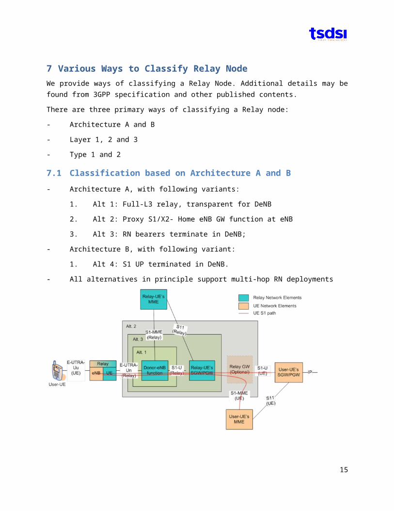
7.1 Classification based on Architecture A and B
- Architecture A, with following variants:
1. Alt 1: Full-L3 relay, transparent for DeNB
2. Alt 2: Proxy S1/X2- Home eNB GW function at eNB
3. Alt 3: RN bearers terminate in DeNB;
- Architecture B, with following variant:
1. Alt 4: S1 UP terminated in DeNB.
- All alternatives in principle support multi-hop RN deployments
13
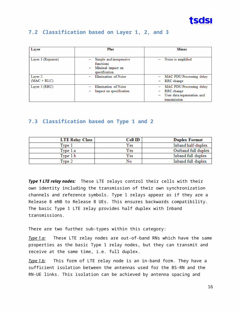
7.2 Classification based on Layer 1, 2, and 3
7.3 Classification based on Type 1 and 2
Type 1 LTE relay nodes: These LTE relays control their cells with their own identity including the transmission of their own synchronization channels and reference symbols. Type 1 relays appear as if they are a Release 8 eNB to Release 8 UEs. This ensures backwards compatibility. The basic Type 1 LTE relay provides half duplex with Inband transmissions.
There are two further sub-types within this category:
Type 1.a: These LTE relay nodes are out-of-band RNs which have the same properties as the basic Type 1 relay nodes, but they can transmit and receive at the same time, i.e. full duplex.
Type 1.b: This form of LTE relay node is an in-band form. They have a sufficient isolation between the antennas used for the BS-RN and the RN-UE links. This isolation can be achieved by antenna spacing and directivity as well as specialized digital signal processing techniques, although there are cost impacts of doing this. The performance of these RNs is anticipated to be similar to that of femtocells.
Type 2 LTE relay nodes: These LTE relaying nodes do not have their own cell identity and look just like the main cell. Any UE in range is not able to distinguish a relay from the main eNB within the cell. Control information can be transmitted from the eNB and user data from the LTE relay.
14
All architectures and types of Relay Node specified in 3GPP require enhancements to eNodeB and EPC elements and therefore in addition to cost of Relay Node, the operators have to pay heavily, for software and hardware upgrades in eNodeB and EPC elements.
15
8 Deployment concernsThe deployment concern and problem with Relay Nodes defined in 3GPP specifications are following:
1. They are not transparent to eNB (this adds to deployment cost)2. eNB must support RN protocol stacks to allow signalling and the transfer of user plane data (adds to
deployment cost)3. Modified air-interface – called as ‘Un’ interface for user and control plane
a. RRC (Radio resource configuration) between RN and ENB (adds cost)b. NAS (Non-Access Stratum) between RN and MME (no change)
4. RN subframe configuration information element (adds cost)a. TDD uplink and downlink subframe configuration patternb. R-PDCCH that includes MBSFN and ABS, etc.c. Relay specific new Scheduler
All architectures and types of Relay Node specified in 3GPP require enhancements to eNodeB and EPC elements and therefore in addition to cost of Relay Node, the operators have to pay, for software and hardware upgrades in eNodeB and EPC elements.
It is generally preferred that network elements be allowed to be placed independently irrespective of other elements in the network. In other words, any placement of a new element should not require modifications in existing deployed elements.
16

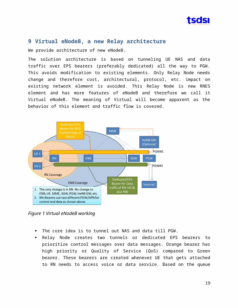
9 Virtual eNodeB, a new Relay architectureWe provide architecture of new eNodeB.
The solution architecture is based on tunneling UE NAS and data traffic over EPS bearers (preferably dedicated) all the way to PGW. This avoids modification to existing elements. Only Relay Node needs change and therefore cost, architectural, protocol, etc. impact on existing network element is avoided. This Relay Node is new RNES element and has more features of eNodeB and therefore we call it Virtual eNodeB. The meaning of Virtual will become apparent as the behavior of this element and traffic flow is covered.
Figure 1 Virtual eNodeB working
The core idea is to tunnel out NAS and data till PGW. Relay Node creates two tunnels or dedicated EPS bearers to prioritize control messages over
data messages. Orange bearer has high priority or Quality of Service (QoS) compared to Green bearer. These bearers are created whenever UE that gets attached to RN needs to access voice or data service. Based on the queue or buffer status exchanged between UE and RN, an RN will create a bearer of a specific bit rate and QoS.
eNB:- unpacks NAS from RN and sends NAS to MME. eNB will be unaware of the NAS and data traffic from UEs attached to RN. UEs (or RN-UE) shown here are only attached to RN for clarity and simplicity.
RN:- sends, encapsulates or tunnels NAS message of RN-UE over dedicated EPS bearer (orange color) towards PGW#1. PGW#1 forwards the NAS message of RN-UE to MME (If encapsulation is performed at RN, then de-encapsulation is performed at PGW#1.) S5/S8 can be configured for
17
roaming UEs. Similarly data traffic is sent by RN towards PGW#2 over dedicated EPS bearer (green color)
Various flavours are possible. E.g. Optionally HeNB GW can be placed between PGW#1 and MME; HeNB GW can decouple control and/or data traffic, send control/NAS messages towards MME and data traffic towards Internet. HeNB GW may be used when there is only one dedicated EPS bearer between RN and PGW. Alternatively we can replace the optional HeNB GW with SGW/PGW, etc.
Note: We assume only one MME in this network for simplicity in explanation. Also, in the figure, the coverage of RN is slightly extended beyond the coverage area of eNB.
As can be inferred, new Relay architecture is possible that will enable low cost roll out in any existing RAN without support from incumbent vendors and without any change to existing network elements and protocol stack. All changes are restricted to Relay Node design only
A critical look at the architecture will enable one see that this is architecturally an eNodeB that is virtually extended and undetectable by eNodeB and EPC elements. So this architecture can be called as virtual eNodeB. For short V-eNodeB. This is similar to macro, micro, pico and femto but with a major difference of non-line of sight (wireless) backhaul. Also this is unlike all Relay architectures proposed till date.
In summary,
A new eNodeB architecture, called Virtual-eNodeB or V-eNodeB is proposed
Without any change to eNB, UE and all EPC elements Without any change to Protocol stack of existing elements All changes are restricted to Relay Node only
Optionally,
with mobility support with out of band with full duplex that reuses cell ID/fully transparent that reuses 3G/2.5G spectrum as backhaul
9.1 Multiplexers for V-NBThe virtual eNodeB (v-NB) requires two types of multiplexers, for data and for control.
9.1.1 Data multiplexer:The virtual eNodeB is proposed to aggregate the data received from UEs within the coverage of v-NB at PDCP layer from the U_u link over to PDCP layer on the uplink U_n towards the Donor eNB. Reverse operation is performed for data for the respective UEs based on unique UE ID.
9.1.2 Control multiplexer:The v-NB is proposed to aggregate the control messages received from UEs within the coverage of v-NB at RRC layer from the U_u link over to the PDCP layer on the uplink U_n towards the
18
Donor eNB. Reverse operations is performed for data for the respective UEs based on unique UE ID.
The multiplexed data and control both form the data part of the v-NB, when the v-NB appears as UE to the Donor eNB. V-NB may have data of its own in addition to the data and control received from the UEs within the coverage of v-NB. Control messages from v-NB are forwarded by Donor eNB as if the v-NB is a UE attached to itself (i.e. the Donor eNB).
[Details of these architectures can be worked out as part of Work Item.]
10Message flow in VeNB based EPSIt is to be impressed that VeNB is for coverage and not for capacity. So we can accept reduction in overall service throughput to bring UEs into coverage who other would not have been in coverage and consequently increasing revenue by coverage enhancement.
In the Figure 2: Message flow, we have UE (U1), Virtual eNodeB (V1), eNB (E1), two SGWs (S1 and S2), two PGWs (P1 and P2), one HeNB-GW (H1) and one MME (M1). U1 is close to V1, far away from E1. U1 is fixed or moves within the coverage of V1. There are two scenarios for serving U1: 1) with hard-handover 2) with soft-handover. In this SWIP we cover hard-handover; when U1 leaves V1 and enters coverage of E1, existing EPS bearer is discontinued.
Figure 2: Message flow
The inactivity timer for V1 is configured as infinity at E1. This network is under the OAM of mobile operator and therefore this assumption is valid.
Below is message flow for mobile originating connection request:
19
1. U1: RRC connection request is sent to V12. V1: RRC connection request is sent to E1. (If inactivity timer is set to infinity, then the ERAB
connection will be already available if it was previously established. There are many other methods to continue the ERAB connection and those can be spelled out as part of Work Item phase. It suffices that method to not terminate ERAB connection are out of the scope to enable vendors to design and implement their preferred methods.)
3. E1: S1-MME(V1) with connection request is sent to M14. M1: Create E1-P1 tunnel with guaranteed bit rate to APN3; this APN3 is operator configured for
V1, V2, etc. For UEs not connected through V1, APN1 is used. For U1 APN2 is used.5. M1: S1-AP(S1-MME(V1) with connection response for V16. E1: Learns S1-AP(S1-MME(V1) and creates ERAB for V17. V1: Encapsulates S1-MME(U1) within data bearer. (It gets tunneled till P1 through E1-P1 bearer
as in next step.)8. E1: S1-UP(S1-MME(U1) by tunneling with TEID of P19. P1: De-encapsulates S1-MME(U1) and transmits towards H110. H1: Transmits S1-MME(U1) to M1, either directly or via S2. (We are assuming only one MME, for
simplicity)11. M1: Create H1-P2 tunnel with guaranteed bit rate to APN2. As mentioned earlier APN2 is used
only for V1, V2, etc. 12. V1: Understands the request for creation of V1-P2 tunnel and establishes a tunnel13. M1: S1-AP(U1) with connection response via H1, P1-E1 tunnel and V1-E1 ERAB14. V1: Learns S1-AP response to U1 and creates ERAB for U115. U1: Now IP packet is transmitted with APN216. V1: Encapsulates the received packet with APN317. E1: Tunnels packet received from V1 and sends towards P118. P1: De-encapsulates packet with TEID=P1 and sends to APN3.19. H1: Receives packet with TEID=P2 and forwards to APN2. (If S1-MME(U1) was sent by V1, then
H1 will send this packet to M1. Else this is S1-UP(U1) towards APN2.)20. P2: De-encapsulates S1-UP(U1) packet with TEID=P2 and forwards to internet via APN2.
Now lets understand the mobile terminating call.
UE2 (U2) under the MME2 (M2) is trying to contact U1. The serving MME (M1) for U1 can be identified via HLR/VLR/HSS as in 3GPP specifications.
Below is the message flow for mobile terminating call:
1. M2: Contacts M1 for LAI/RAI/TAI2. M1: Knows U1 is in H1 and sends S1-MME(U1-paging) to V1 via H1 (or S2)3. V1: Pages U1. (If there were many VeNBs then all of them are paged by H1 (or S2)4. U1: Follows Mobile Originating flow as described above after reception of the page.
20
Hand-over of U1 from V1 to E1 is not of primary concern in coverage scenario when the UEs are primarily fixed and DSL-like broadband connection is required with restricted mobility. However, if HO is needed, then S1-HO can be used. The anchoring of bearers at P1 and/or P2 is also feasible as the IP traffic on APN1 can be also re-directed onto APN3.
The proposed architecture involves two types of PGW and SGW: one of smaller capacity and another of larger capacity. It is possible to reduce the count to one, each, by having back-and-forth flow through same SGW and PGW. This part can be worked out during Work Item Phase or be left to the operator’s choice.
11Protocol StackDouble IP stack is not uncommon in 3GPP, for example:
1. 3GPP Family of access (3GPP spec allows dual IP stack in EPC)2. Trusted non-3GPP Accesses with PMIP and GTP (3GPP spec allows dual IP stack in EPC)3. Trusted non-3GPP Accesses with DSMIPv6 (3GPP spec allows dual IP stack in LTE and EPC)4. Untrusted non-3GPP Accesses with PMIP and GTP (3GPP spec allows dual IP stack in LTE and
EPC)
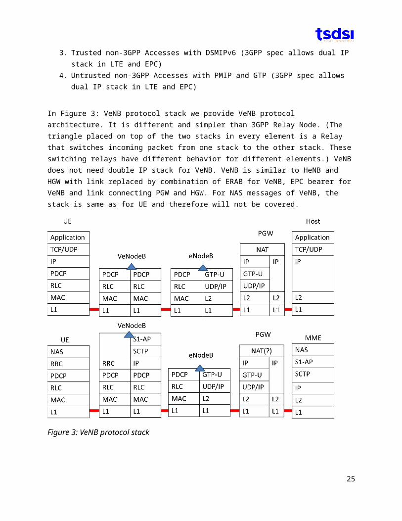
In Figure 3: VeNB protocol stack we provide VeNB protocol architecture. It is different and simpler than 3GPP Relay Node. (The triangle placed on top of the two stacks in every element is a Relay that switches incoming packet from one stack to the other stack. These switching relays have different behavior for different elements.) VeNB does not need double IP stack for VeNB. VeNB is similar to HeNB and HGW with link replaced by combination of ERAB for VeNB, EPC bearer for VeNB and link connecting PGW and HGW. For NAS messages of VeNB, the stack is same as for UE and therefore will not be covered.
21
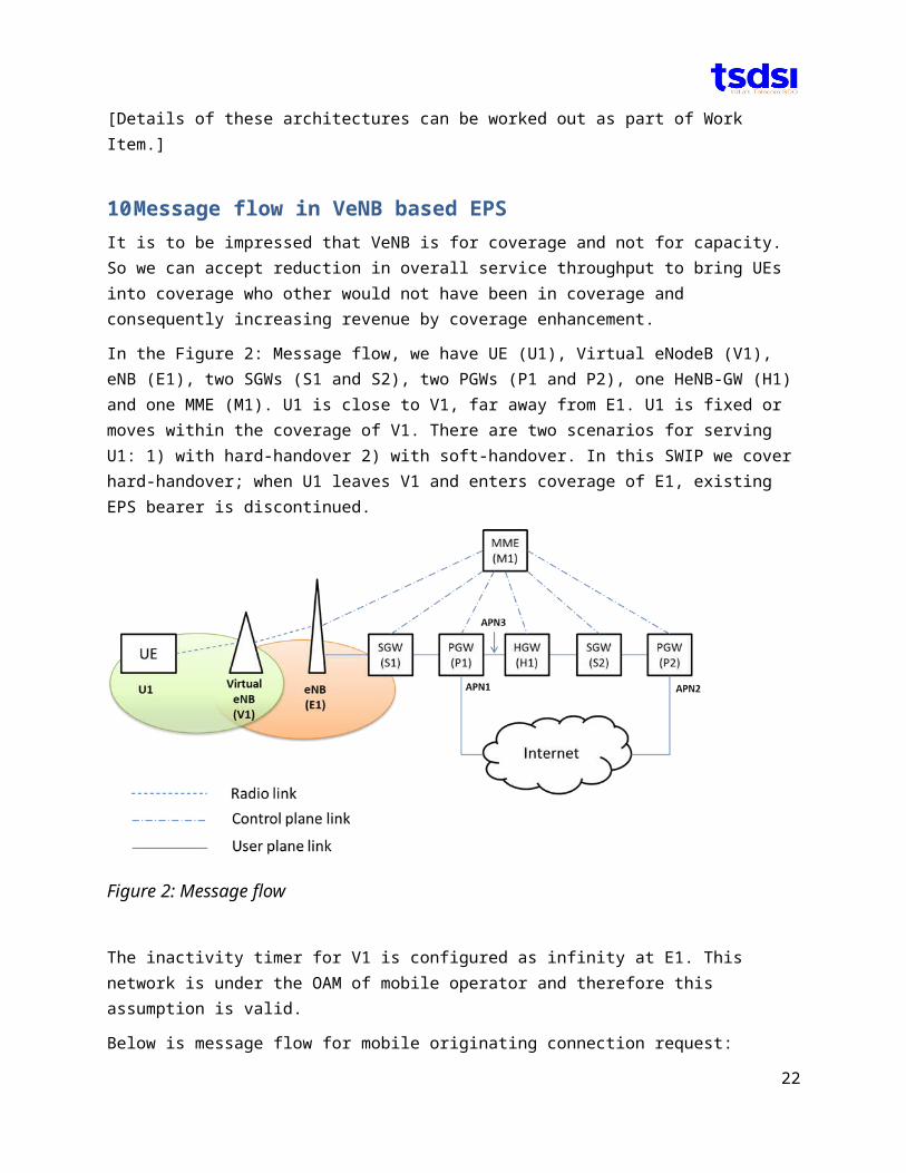
Figure 3: VeNB protocol stack
12Phased VeNB Deployment StrategyWe provide 4 phased deployment strategy for VeNB.
1. Phase 1: Primary DSL-like data connectiona) Reduction in UE throughput is acceptable for overall increase in cell throughput and revenueb) Seamless Handover is not requiredc) IP-session continuity is not required
2. Phase 2: Seamless Handovera) IP-session continuity is not required
3. Phase 3: IP-session continuity
4. Phase 4: Further enhancements to individual network elements
22
13Deployment Examples of Virtual eNodeBIn the referenced contribution, a new alternative for Relaying was proposed and a new architecture was suggested that was called as Virtual eNodeB.
The three deployment examples of Virtual EnodeB are illustrated below:
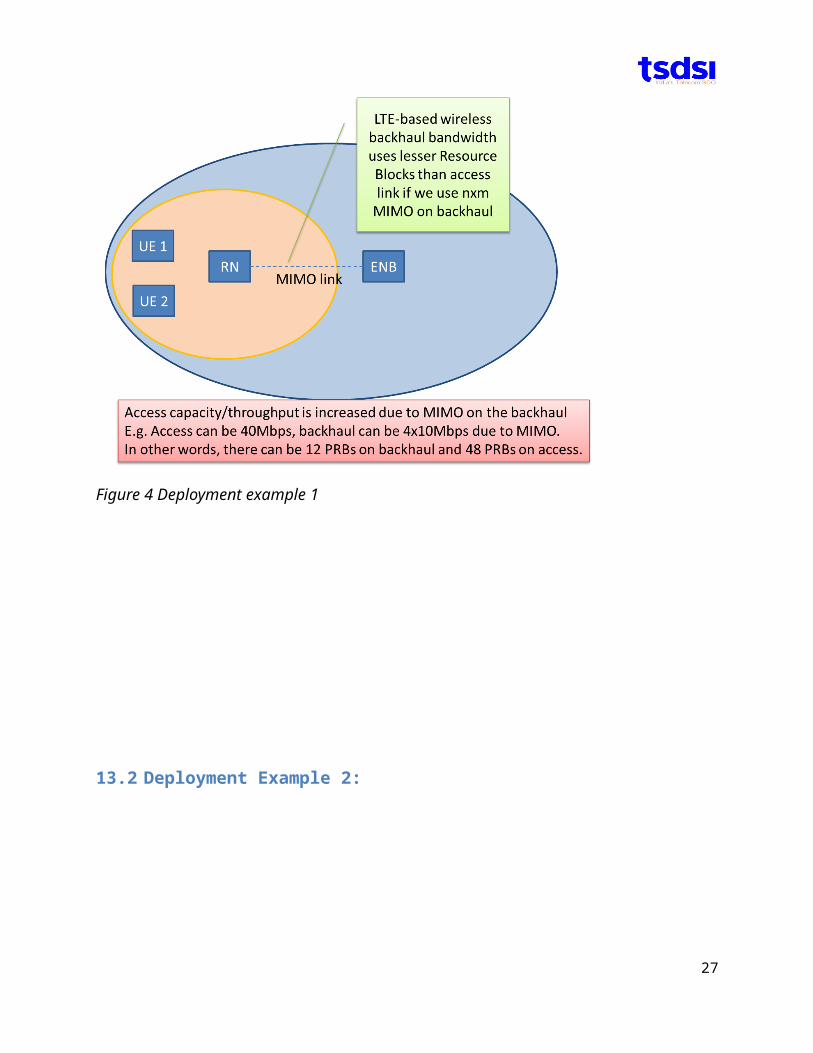
13.1 Deployment Example 1
Figure 4 Deployment example 1
23
14Summary
Three deployment examples of Virtual eNodeB were provided for faster and ultra-low cost roll out of Relaying solution.
15Revision history
Version Date PreparedReleased by Change Description
Version 0.1.0 20150909
9th September, 2015
Champion: Vinod Kumar, Tejas Networks SG1-WG1-MTG1
Version 0.2.0 3rd November, 2015
Champion: Vinod Kumar, Tejas Networks SG1-WG1-MTG2
Version 0.3.0 29 January, 2016
Champion: Vinod Kumar, Tejas Networks SG1-WG1-MTG3
Version 0.1.0 22th June, Champion: Vinod Kumar, Tejas Networks SG1 WG1 MTG4
26
We highlighted the various architectures of Relay Nodes as proposed by many SDOs.
We also highlighted the shortcomings of Relay Nodes defined towards building new type of Relay Node different from what other SDOs are proposing, without any impact what-so-ever to existing RAN/CN deployment and without any support from incumbent vendors or dependency on brownfield deployments.
New eNodeB architecture, called Virtual-eNodeB or V-eNodeB is proposed:
Without any change to eNB, UE and all EPC elements Without any change to Protocol stack All changes are restricted to Virtual-eNodeB only
Optionally,
with mobility support with out of band with full duplex that reuses cell ID/fully transparent
that reuses 3G/2.5G spectrum as backhaul.


![INTRODUCTION - TSDSI | Welcome to · Web viewDraft date, if not published [for status information] Publication date of the standard [for status information] Intentionally left Blank](https://img.pdfslide.net/doc/110x75/5abc73547f8b9af27d8df140/introduction-tsdsi-welcome-to-viewdraft-date-if-not-published-for-status-information.jpg)