Embed Size (px)
Citation preview
Journal of Ship Research, Vol. 41, No. 3, Sept. 1997, pp. 230-240
Interaction Equation for the Collapse of Tankers and Containerships Under Combined Bending Moments
J. M. Gordo, and C. Guedes Soares
The ultimate collapse of the midship section of tankers and container ships under combined vertical and horizontal bending moments is determined by an approximate method. That accounts for the load shortening contribution of each plate and stiffener assembly, thus being able to construct the moment-curvature relation for the hull girder. The method is applied to study five tankers and six container ships and the results are used to define an interaction formula proposed to account for the combination of the load effects for design purposes.
Introduction
THE IMPROVED knowledge of the collapse behavior of plate el- ements as well as the generalization of limit state design of ship structures has led to the development of various approximate methods to predict the collapse load of the ship hull girders.
While the original formulation of this problem can be at- tributed to Caldwell (1965) who considered the collapse of the hull girder, including the degrading effect of plate buckling, and to Faulkner (1965) who proposed a simplified method to pre- dict the collapse load of simple plate elements, several more recent proposals have dealt with various algorithms to achieve that aim.
Smith (1977) was the first to propose a method to account for the behavior of each individual element in the calculation of the ultimate behavior of the hull girder. This was an hy- brid procedure based mainly on a finite element formulation but the plate behavior was described by pre calculated load deformation curves.
Several other authors have proposed alternative methods to perform that prediction. Billingsley (1980): Adamchak (1984): Rutherford & Caldwell (1990) and Gordo et al (1996) have chosen to develop simplified models of structural behavior of the stiffened plate elements in order to construct the global moment curvature relation of the ship hull girder.
Other authors have chosen a different line of work by devel- oping simplified finite element formulations. Examples of such type of approaches are the contributions of Hori et al (1991), Yao & Nikolov (1992), Paik (1992), and of Bai et al (1993). These simplified methods contrast with the heavy computa- tional approach taken by Kutt et al (1985): which proved not to be very practical for adoption in a design type of environ- ment
The method used in this work is based on a simplified for- mulation of the behavior of plate-stiffener assemblies, described in Gordo & Guedes Soares (1993). The contribution of each el-
’ Unit of Marine Technology and Engineering, Instituto Superior TQcnico: Au. Rovisco Pais, 1096 Lisboa, Portugal.
Manuscript received at SNAME headquarters May 23, 1996.
ement to the moment curvature relation of the ship hull was described in Gordo et al (1996), and the predictions of this method were compared with various experimental results in Gordo & Guedes Soares (1996), showing a very good correla- tion.
The work reported in those papers has considered the hull collapse under vertical bending moment, which is indeed the most important load effect in that context. However, in many types of ships, the combined effect of the vertical and the hori- zontal bending moments is important and this work deals with the collapse of ship hulls under that combined load effect.
As in the case of biaxial compressive strength of plates (Guedes Soares & Gordo 1996), the nature of the interaction problem requires the solution of two issues. One is the collapse load in each individual mode, which will be used as a normal- izing factor in the interaction formula. The second problem is the interaction formula itself in order to adequately describe the combined effect of vertical and horizontal collapse moment.
The problem of the interaction relation for the collapse of hull sections under combined loading was addressed in a pre- liminary study by Gordo & Guedes Soares (1995) who analyzed the case of four single skin tankers. Mansour et al (1995) have also addressed this problem although using a different method to predict the collapse load and a different interaction formula.
The present paper extends the earlier work by considering five additional tankers with different configuration i.e., with double hull and with double bottom while the earlier study only contemplated single skin tankers. Furthermore, in order to cover the range of representative hull types, six container ships are also included in the calculations.
Finally, one has to note that the ultimate vertical sagging moment is normally different than the ultimate vertical hog- ging moment which requires a separate treatment for hogging and sagging when the ship is combined horizontal and vertical moment in order to use non dimensional equations in design.
Elastic behavior under combined moment
As it is well known the basic equation that relates the applied vertical and horizontal bending moments to the longitudinal
230 SEPTEMBER 1997 0022-4502/97/4103-0230$00.47/0 JOURNAL OF SHIP RESEARCH
stresses are very simple and may be resumed as followed:
Mz.y My.x
uz=-z-- IY \ /
or it may expressed as a function of the total moment by:
ut. y . coscp
TG= Is x . sin ‘p -~
IY (2)
where ‘p is the angle that the bending moment vector makes with the base line and z and y are the coordinates of the point in a referential located in any point of the neutral axis. For a given point of the cross section this relation is constant until the yield stress of the material is reached in any point of the section. Once the yield stress is reached in any point the neutral axis moves away from its original position and thus the constancy of the relation may be broken. Due to the same reason the relation between the angle of the moment vector cp and the angle of the neutral axis 0 is constant in the linear elastic range but looses it when some plasticity is already present. This relation may be expressed by:
For the analysis of the combined moment our interest should, however, be concentrated in the maximum moment that the cross section may sustain at any combination of vertical and horizontal moments until the first yield is reached and one should note that the first yield happens in the most faraway point to the neutral axis.
At this point (z’, y’), the magnitude of the moment vector may be expressed as a function of the angle between the neutral axis and the base line 0 by:
M - aolx 1+K;.tan20
Y’ 1- KytanO
where Kg is equal to x’/y’, KI is I,/I, and the horizontal and vertical components of the bending moment are given by:
and
111, = .%k 1 y’ l-KytanO
UOIY My = - KY tan .Q
x’ 1- Kytan6
The first term of the product in equations (5) and (6) denotes the pure vertical and horizontal bending moments for 0 and 90 deg respectively, and the second term shows that the variation with 0 is not linear.
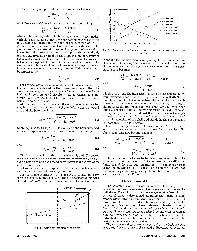
Let us consider two examples: the first is a symmetric square section and the second a rectangular one.
For the square section KY is -1 and KI is 1, thus one have the pure vertical moment equal to the pure horizontal one with the value MO = 2a,I/a, where a is width of the section and I
, Element i, M
I
Fig. 1 Combined bending of hull girder
SEPTEMBER 1997
- . - Rectangular-Mix
Comparison of first yield criteria for square and rectangular cross sections
is the inertial moment about any principal axis of inertia. Fur- thermore, in this case, 0 is always equal to cp which means that the moment vector is always over the neutral axis. The equa- tions 4 to 6 become:
M xg=
(cosO)-~ Mz 1 -zz 1 +tanB’ M0 lftan6
and s- tan8
MO -1 (7)
which shows that the interaction is not circular and the mini- mum moment is achieved at 45 deg with a value of 0.707M0. In fact the interaction between horizontal and vertical moment is linear as it may be seen from equation 1 making oZ = cr, and if the point at the first yield happens is the same whichever the angle 0. For usual ship hull forms this situation is almost satis- fied specially if the deck is almost flat. In any case is the angle of heel is greater than 10 deg the first yield is always located at the intersection of the shell and the deck, thus the relation is linear from 10 to 90 degrees.
For the rectangular section let us consider KY = -2 and KI = 3, which are values close to those found in ships. The above equations now become equal to:
M dm Mz 1 -zz MZO 1+2tan0 ’ x= 1+2tan8
and J&- -2 tan Q - MY, 1+2tanB (8)
The interaction continues to be linear, equation 1, but the variation of the components of the moment is now different, figure 2, and the minimum magnitude of the moment vector is now at an angle Q of 10 degrees, approximately. Note that corresponding cp is now given by the relation tan cp = 3 tan 8, and thus ‘p is around 30 deg.
Description of the method
The assessment of a moment-curvature relationship is ob- tained by imposing a sequence of increasing curvatures to the hull girder. For each curvature, the average strain of each beam- column element is determined assuming that plane sections remain plane after the curvature is applied. These values of strain are, then, introduced in the model that represents the load-shortening behavior of each element (Guedes Soares & Gordo 1993) and the load sustained by each element is cal- culated. The bending moment resisted by the cross section is obtained from the summation of the contributions from the individual elements. The calculated set of values defines the desired moment-curvature relation.
The most general case corresponds to that in which the ship is subjected to curvature in the x- and y-directions, respectively
JOURNAL OF SHIP RESEARCH 231
The condition to determine the correct position of the neutral 0.9 , 0.8
5 0.7 8 0.6 h 0.5 ul g 0.4 2 0.3 s 0.2
0.1 0.0 I I I I
0.0 0.5 1.0 1.5 2.0 2.5
Normalised Strain
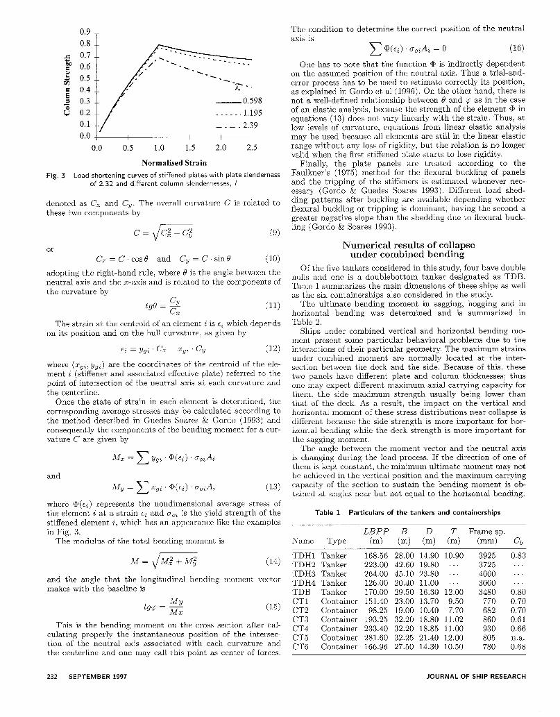
Fig. 3 Load shortening curves of stiffened plates with plate slenderness of 2.32 and different column slendernesses.
denoted as C, and C,. The overall curvature C is related to these two components by
c+-c; or
C, =C.COS~ and C, =C.sinQ (10)
adopting the right-hand rule, where 0 is the angle between the neutral axis and the x-axis and is related to the components of the curvature by
tgf3 = 2 (11) z
The strain at the centroid of an element i is ei which depends on its position and on the hull curvature, as given by
Ei = ygi Cz ~ Xgt Cy (12)
where (x9%; ygi) are the coordinates of the centroid of the ele- ment i (stiffener and associated effective plate) referred to t,he point of intersection of the neutral axis at each curvature and the centerline.
Once the state of strain in each element is determined, the corresponding average stresses may be calculated according to the method described in Guedes Soares & Gordo (1993) and consequently the components of the bending moment for a cur- vature C are given by
and
(13)
where @(E<) represents the nondimensional average stress of the element i at a strain ei and co2 is the yield strength of the stiffened element i, which has an appearance like the examples in Fig. 3.
The modulus of the total bending moment is
and the angle that the longitudinal bending moment vector makes with the baseline is
(15)
This is the bending moment on the cross section after cal- culating properly the instantaneous position of the intersec- tion of the neutral axis associated with each curvature and the centerline and one may call this point as center of forces.
axis is c (a(~~) . goiAi = 0 (16)
One has to note that the function @ is indirectly dependent on the assumed position of the neutral axis. Thus a trial-and- error process has to be used to estimate correctly its position, as explained in Gordo et al (1996). On the other hand, there is not a well-defined relationship between 0 and cp as in the case of an elastic analysis, because the strength of the element Q, in equations (13) does not vary linearly with the strain. Thus, at low levels of curvature, equations from linear elastic analysis may be used because all elements are still in the linear elastic range without any loss of rigidity, but the relation is no longer valid when the first stiffened plate starts to lose rigidity.
Finally, the plate panels are treated according to the Faulkner’s (1975) method for the flexural buckling of panels and the tripping of the stiffeners is estimated whenever nec- essary (Gordo & Guedes Soares 1993). Different load shed- ding patterns after buckling are available depending whether flexural buckling or tripping is dominant, having the second a greater negative slope than the shedding due to flexural buck- ling (Gordo & Soares 1993).
Numerical results of collapse under combined bending
Of the five tankers considered in this study, four have double hulls and one is a doublebottom tanker designated as TDB. Table 1 summarizes the main dimensions of these ships as well as the six containerships also considered in the study.
The ultimate bending moment in sagging, hogging and in horizontal bending was determined and is summarized in Table 2.
Ships under combined vertical and horizontal bending mo- ment present some particular behavioral problems due to the interactions of their particular geometry. The maximum strains under combined moment are normally located at the inter- section between the deck and the side. Because of this, these two panels have different plate and column thicknesses; thus one may expect different maximum axial carrying capacity for them, the side maximum strength usually being lower than that of the deck. As a result, the impact on the vertical and horizontal moment of these stress distributions near collapse is different because the side strength is more important for hor- izontal bending while the deck strength is more important for the sagging moment.
The angle between the moment vector and the neutral axis is changing during the load process. If the direction of one of them is kept constant, the minimum ultimate moment may not be achieved in the vertical position and the maximum carrying capacity of the section to sustain the bending moment is ob- tained at angles near but not equal to the horizontal bending.
Table 1 Particulars of the tankers and containerships
LBPP B D T Frame sp. lXame Type cm) cm) cm) cm) cmrn) cb
TDHl Tanker 168.56 28.00 14.90 10.90 3925 TDH2 Tanker 223.00 42.60 19.80 . 3725 TDH3 Tanker 264.00 45.10 23.80 ..’ 4000 TDH4 Tanker 126.00 20.40 11.00 3000 TDB Tanker 170.00 29.50 16.30 12.00 3480 CT1 Container 151.40 23.00 13.70 9.50 770 CT2 Container 98.25 19.00 10.40 7.70 682 CT3 Container 193.25 32.20 18.80 11.02 860 CT4 Container 233.40 32.20 18.85 11.00 930 CT5 Container 281.60 32.25 21.40 12.00 805 CT6 Container 166.96 27.50 14.30 10.50 780
0.83
. . 0.80 0.70 0.70 0.61 0.66 na. 0.68
232 SEPTEMBER 1997 JOURNAL OF SHIP RESEARCH
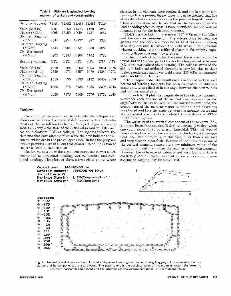
Table 2 Ultimate longitudinal bending
moment of tankers and containerships
Bending Moment TDHl TDH2 TDH3 TDH4 TDB
Yield (MN.m) 2501 9762 14475 1120 4289 Plastic (MN.m) 4095 13159 19054 1487 4857 Ultimate Sagging
(MN.m) 2644 8654 12297 887 3336 Ultimate Hogging
(MN.m) 3334 10994 16334 1280 4083 Ult. Horizontal
(MN.m) 4802 16343 22308 1792 4734
Bending Moment CT1 CT2 CT3 CT4 CT5 CT6
Yield (MN.m) 1920 608 5052 4093 9931 2578 Plastic (MN.m) 2389 973 6357 6079 11259 3273 Ultimate Sagging
(MN.m) 1513 596 4333 4132 10469 2679 Ultimate Hogging
Ul?!!Zont al 1688 875 5435 5455 8398 2845
stresses in the elements were produced, and the last point cor- responds to the present figure. Thus, it can be checked that the stress distribution corresponds to the point of largest moment. These curves allow one to see that in the two examples the load shedding after collapse is more significant for the vertical moment than for the horizontal moment.
TDH2 has the bottom in tension (327 MPa near the bilge) and the deck in compression. The intersections between the girders and the deck are modeled as hard corners, implying that they are able to sustain the yield stress in compression without buckling, but the stiffened plates in the vicinity expe- rience collapse at a much lower stress.
In the doublebottom tanker the same characteristics may be found, but in this case part of the bottom has yielded in tension (8% of the normalized plastic strain). The collapse stress of the side and bulkhead stiffened elements is very low due to their higher slenderness and lower yield stress, 235 MPa as compared with 355 MPa in the deck.
The collapse under the simultaneous action of vertical and horizontal bending moments has been calculated for different combinations as reflected in the angle between the neutral axis and the horizontal axis.
(MN.m) 2629 1378 7009 7576 13756 4645
Tankers
The computer program used to calculate the collapse load allows one to follow the state of deformation of the plate ele- ments as the overall load is being developed. Figures 3 and 4 show for example the state of the double-skin tanker TDH2 and the doublebottom TDB at collapse. The squares indicate the elements that have already failed while the dots indicate the el- ements which are in the pre-collapse state. In fact the program output provides a set of colors that allows also an indication of the stress level in each element.
The figures also show three moment curvature curves which correspond to horizontal bending, vertical bending and com- bined bending. The plots of these curves show points where
Figures 6 to 10 plot the magnitude of the ultimate moment vector for each position of the neutral axis, measured as the angle between the neutral axis and the horizontal axis. Also, the components of the moment vector about the main directions are plotted and thus the angle between the moment vector and the horizontal axis may be calculated; this is shown as ATAN in the figure legends.
The variation of the vertical component of the moment, AJZ, is almost linear from sagging (0 deg) to hogging (180 deg) when one could expect it to be nearly sinusoidal. This last type of behavior is observed on the variation of the horizontal compo- nent, A&. The function is, in this case? fuller than a sinusoid and very close to a parabola. Because of the linear variation of the vertical moment, some ships show minimum values of the ultimate moment lower than the sagging or hogging moment. However, the difference of values is not very high and thus a constancy of the ultimate moment at low angles around pure sagging or hogging may be considered.
Curuature= .14048E-03 /rn Bending Homent= .9057OE+04 MN.m Iteration vi.22 Maximum Strain= 1.28ICompression) Minimum Strain= -.SZITension) Ham-
C
-327 Stresses
Fig. 4 Geometry and stress state of TDH2 at collapse with an angle of heel of 10 deg (sagging). The moment curvature relation and its components are also plotted. The upper curve is the absolute value of the moment vector, the lowest is
represent horizontal component and the intermediate the vertical component of the moment vector.
SEPTEMBER 1997 JOURNAL OF SHIP RESEARCH 233

Fig. 5 Geometry and stress state of TDB at collapse with an angle of heel of 5 deg (sagging). The moment curvature relation and its components are also plotted
AngfeofNAandxx
Fig. 6 Double-skin tanker-TDHl
Angle of NAand xx
Fig. 7 Double-skin tanker-TDH2
AngleofNAandar
Fig. 8 Double-skin tanker-TDH3
The
AngleofNAmda
Fig. 9 Double-skin tanker-TDH4
5co3 180
4cm 160 3cKx 140 $
2cm -z 120 ~ loo3
ID3 I
0 I
-loco 8o $
-2m 60%
t
-3m 402
-4CCO 20
-5mx -~- 0
Angle of NA and xx
Fig. 10 Double-skin tanker-TDB
interactions between vertical and horizontal moments are plotted in Figs. 11 to 15. Several interaction curves that vary from linear to quadratic are plotted so as to compare the calculated points for sagging and hogging with the interactions.
The general governing equation is given by:
(17)
where MUV and A&h are, respectively, the vertical and hor- izontal ultimate moment. The ultimate vertical moment may be the sagging or the hogging ultimate moment depending upon which is the combination under analysis. The parameter Q is
234 SEPTEMBER 1997 JOURNAL OF SHIP RESEARCH

1.2 T------------- --?---“j 0 SAG/ I I 1 I I * HOG /
/ --- 2.00 I
0.6 MY
0.4
0.0 1 I I
0.0 0.2 0.4 0.6 0.8 1.0
Mx
Fig. 11 Double-skin tanker-TDHl
0.0 0.2 0.4 0.6 0.8
Mx
Fig. 14 Double-skin tanker-TDH4
1.0
1 .o
0.9
0.8
0.7
0.6
0.5 MY 0.4
0.3
0.2
0.1
0.0
. SAG
_____. 1.3
---- 1.50
0.6 MY
0.4
0.2
0.0 0.0 0.2 0.4 0.6 0.8
Mx
Fig. 15 Double-skin tanker-TDB
1.0 0.0 0.2 0.4 0.6 0.8 1.0
Mx
Fig. 12 Double-skin tanker-TDH2 tentatively used in the graphics of Figs. 11-15 with the values of 1.0, 1.5, 1.66 and 2.0.
Good correlation is achieved with Q between 1.5 and 1.66. It does not seem necessary to use different exponents in hog- ging and sagging for these types of ships. In fact, the double- skin tankers (TDHl, TDH2, TDHS, TDH4) have the hogging moment interaction above the sagging one near the horizontal moment, My/M, > 1, while the reverse happens with the dou- blebottom tanker (TDB). However, near pure vertical bending, TDH2, TDH3 and TDH4 have the same or lower exponent in hogging than in sagging although the differences are not impor- tant. The same exponent was found in Gordo & Guedes Soares (1995) for the other four single-skin tankers. In these cases, not much difference was found between the interaction formulas for sagging and hogging.
The behavior under hogging and sagging conditions is more clearly shown in Figs. 16 to 20, where the negative values of the abscissa represent hogging and the positive ones sagging. These figures plot the left-hand side of equation (17) for different val- ues of rr. In fact, these values, denoted as R, can be integrated as the bias of the method which should result in unity.
When a is equal to 1.66, there are some optimistic results for TDHl, TDH2, TDH3 and TD6 in hogging and for all hulls
1.2 l SAG + HOG
0.6 MY
0.4
0.2
0.0
0.0 0.2 0.4 0.6 0.8
MX
Fig. 13 Double-skin tanker-TDH3
1.0
SEPTEMBER 1997 JOURNAL OF SHIP RESEARCH 235

DBHl
n,T !
-I 0 -0 5 00 05 10
MXIM
Fig. 16 Double-skin tanker-TDHl
DBHZ
DBH3
I nr; I
-I 0 -0 5 00 OS 10
Mxmf
Fig. 18 Double-skin tanker-TDH5
Curuature= .17970E-03 /m Bending Moment= .1734OE+O4 HN.m Iteration n. 19 Maximum Strain= l.Z3ICompression~ Hinimum Strain= -1.03ITensian)
DBH4
R !
.I.0 -0 5 00 05 1.0
Munt
Fig. 19 Double-skin tanker-TDH6
TDB
r--‘---& /-----I
-I 0 -0.5 00 0.5 1.0
MdM
Fig. 20 Double-skin tanker-TDB
in sagging. If the interaction curve uses cy equal to 1.5 it then becomes conservative, but the corresponding bias, R, is close to one and the scatter is low, as may be seen in Figs. 16 to 20, where the greater part of the points is within a band of 5% of one.
Thus, the main conclusions one may extract from this set of figures is that the exponent 1.66 gives conservative results and 1.0 may be taken as a lower-bound interaction formula. The scatter of the results is low and very consistent along the range of the A&/M ratio.
Fig. 21 Geometry and stress state of CT5 at collapse with an angle of heel of 10 deg (hogging). The moment curvature relation and its components are also plotted
236 SEPTEMBER 1997 JOURNAL OF SHIP RESEARCH

Fig. 22 Geometry and stress state of CT5 at collapse with an angle of heel of 10 deg (sagging). The moment curvature relation and its components are also plotted
Fig. 23 Containership CT1
Angle of NA andxx
Fig. 26 Containership CT4
Angle of NA and xx Angle of NA and xx
Fig. 24 Containership CT2 Fig. 27 Containership CT5
Angle of NA and xx
Fig. 25 Containership CT3 Fig. 28 Containership CT6
SEPTEMBER 1997 JOURNAL OF SHIP RESEARCH 237

CT1
1.2 I i 0 SAG
1 0 HOG
L~~~~~-*--j~-.-.--.,--~~~. - - - 2.00 - . . -8
‘. ----m.1.20
0.8 0.8
0.6
MY
0.4
0.6
MY
0.4
0.2
CT4 CT3
.mT
0.8
0.6
MY
0.4
1.2
1.0
0.8
0.6
MY
0.4
I 0.2 t
I 0.0 L
I 0 SAG
* HOC ii
0.0 0.2 0.4 0.6 0.8 1.0 0.0 0.2 0.4 0.6 0.8 1.0
Mx Mx
CT5
1.2 -.----- 0 SAG 1
* HOGS 1.2 SAG
HOG
1.0
0.8
‘\ 0’. 0.6
MY
0.4
0.2
0.0
0.6
MY
0.4
0.2
0.0 0.2 0.4 0.6 0.8 1.0 0.0 0.2 0.4 0.6 0.8 1.0
Mx Mx
Fig. 29 Interaction relations between vertical and horizontal moment in collapse of containerships
238 SEPTEMBER 1997 JOURNAL OF SHIP RESEARCH

Containerships
The process used for the tanker calculations was applied to the containerships. Figures 21 and 22 show the hull cross section at collapse for two containerships.
The principal differences are a consequence of the absence of part of the deck and are due also to the existence of stockier plate elements in this region as compared with those in the tankers. Thus, the containerships are more sensitive to buckling under hogging than under sagging.
Due to the low position of the neutral axis in upright bend- ing, which promotes lower strains in the bottom than in the deck, the maximum strength to resist the bending moment is normally achieved at angles of heel higher than 90 deg, i.e., with some degree of hog. The behavior of the containerships is represented in Figs. 23 to 28.
CT1 and CT3 have a linear variation of the vertical compo- nent of the moment vector with an increase in the angle of heel as in the tankers, but for the others this function is far from linear, presenting three points of inflection at 30, 100 and 140 deg approximately. It is not an easy task to justify this type of behavior, but one may note that it is associated with the three main regions of the variation of the angle between the moment vector and the neutral axis direction. This angle grows steadily until 30-40 deg of the angle of the NA axis about the horizon- tal, which means that the horizontal component of the vector
CT1
t . .._. ---.-;.---. . . . . . ..---.------- -@,7.-------
-1.0 -0.5 0.0 OS 1.0
Mm
CT2
-1.0 -0.5 0.0 0.5 1.0
MUM
CT3
R
moment grows faster than the reduction in the vertical compo- nent of the moment. From 70 to 130 deg the ATAN function is relatively flat, which means that the direction of the moment vector is almost insensitive to the variation of direction of the neutral axis. For angles higher than 160 deg the first behavior is repeated but now in hogging.
Figure 29 shows the interaction curves for the containerships. It is evident that the exponent for hogging is higher than that for sagging. Conservative values of the exponent are 1.2 for sagging and 1.5 for hogging. Different exponents for vertical and horizontal moments were not considered necessary.
Figure 30 summarizes the performance of the interaction curves as a function of the contribution of the vertical compo- nent of the ultimate moment. In most cases, the use of the rec- ommended values for the exponent generates functions that are within a band of error of lo%, and this band reduces dramati- cally near pure hogging and sagging, respectively j&/M = -1 and 1, which are the regions of interest.
At low levels of the vertical component of the moment, MZ, the horizontal component exceeds the moment achieved at 90 deg of heel, which is represented in Fig. 29 by the points with A& greater than 1.0. In this region the difference of behavior between sagging and hogging is very marked even for those ships with similar behavior near the upright position, CT2 and CT4. For these two ships the best exponent of the interaction formula seems to be 1.5 for hogging and sagging.
CT4
~
I /
.I.0 -0 5 0.0 0.5 1.0
MXIM
CT5
-1.0 -0.5 0.0 0.5 1.0
MdM
CT6
Fig. 30 Plot of bias factor for various containerships
SEPTEMBER 1997 JOURNAL OF SHIP RESEARCH 239

The most abnormal behavior, with CT5, is a direct conse- quence of the different geometry of this ship when compared with the others. The differences are in the relations of both L/B (length/breadth) and L/D (length/depth) of the ship as well as in the thickness of the plate on the deck, which is 50 mm in the present case.
Conclusion
Based on the results of the collapse calculations performed for double-hull and doublebottom tankers and for container- ships, as well as the earlier results for single-hull tankers, it is recommended that equation (17) be used to predict the interac- tion between vertical and horizontal moments in the collapse of ship hulls. The ultimate vertical and horizontal moments that are normalizing factors are calculated with the present method.
The proposed interaction formula should have an exponent of 1.5 for tankers in both hogging and sagging. This value rep- resents a lower-bound curve and the small number of cases analyzed do not allow further conclusions.
The exponent of the interaction formula for containerships is different for sagging and hogging. Conservative values for these two cases are 1.2 and 1.5, respectively. However, the scatter of the results relative to the interaction formula is much higher than on the tankers when the bending moment varies from pure sagging to pure hogging. Some abnormal types of behavior may be present due to the special geometry of the ship, i.e., the absence of part of the deck and the stockiness of the deck plating.
Acknowledgments
This work has been performed as part of a research project (B/E 4554) “Reliability Methods for Ship Structural Design (SHIPREL) ,‘j which has been partially funded by the Commis- sion of the European Union under the BRITE/EURAM Con- tract No. CT91-0501, and which involves the following addi- tional participants: Bureau Veritas, Germanischer Lloyd, Reg- istro Italian0 Navale and the Technical University of Denmark.
References
ADAMCHAK, J. C. 1984 An approximate method for estimat- ing the collapse of a ship’s hull in preliminary design. Pro- ceedings, Ship Structure Symposium ‘84, SNAME, 37-61.
BAI: Y., BENDIKSEN, E.. AND PETERSEN, P. T. 1993 Collapse analysis of ship hulls. nilarine Structures, 6, 485-507.
BILLINGSLEY, D. W. 1980 Hull girder response to extreme bending moments. Proceedings, 5th STAR Symposium, SNAME, 51-63.
CALDWELL, J. B. 1965 Ultimate longitudinal strength. Trans. Royal Institution of Naval Architects 10’7, 411-430.
FAULKNER, D. 1965 Contribution to the discussion of Cald- well (1965). Trans. Royal Institution of Naval Architects 107.
FAULKNER, D. 1975 A review of effective steel plating for use in the analysis of stiffened plating. JOURNAL OF SHIP RESEARCH, 19, l-17.
GORDO, J. M. AND GUEDES SOARES, C. 1993 Approximate load shortening curves for stiffened plates under uniaxial compres- sion, Integrity of Offshore Structures--5, D. Faulkner et al, Eds., EMAS, 189-211.
GORDO, J. M. AND GUEDES SOARES, C. 1995 Collapse of ship hulls under combined vertical and horizontal bending mo- ments, Proceedings, International Symposium on Practical Design in Shipbuilding (PRADS 95), Seoul, Korea, 2, 808- 819.
GORDO, J. M. .4ix~ GUEDES SOARES, C. 1996a Approximate method to evaluate the hull girder collapse strength. Mm-he Structures, 9, 3-4, 449-470.
GORDO, J. IvI., GUEDES SOARES, C.: AND F.WLKNER, D. 1996 Ap- proximate assessment of the ultimate longitudinal strength of the hull girder. JOURNAL OF SHIP RESEARCH, 40, 1, March, 60-69.
GUEDES SOARES, C. AND GORDO; J. 1\/I. 1996b Compressive strength of rectangular plates under biaxial load and lateral pressure. Thin- Walled Structures, 24, 231-259.
HORI, T.: SEKIHAMA, AND RASHED. S. M. H. 1991 Structural design by analysis approach applied to a product oil carrier with unidirectional girder system. Trans. RINA, 133, 199- 215.
Ku?‘T, L. M., PIASZCZYK, C. M.. CHEN; Y. K., AND LIU, D. 1985 Evaluation of the longitudinal ultimate strength of various ship hull configurations. Trans. SNAME, 93, 33-53.
MANSOUR, -4. E.: LIN, Y. H. AND PAIK, J. K. 1995 Ultimate strength of ships under combined vertical and horizontal mo- ments. Proceedings, International Symposium on Practical Design in Shipbuilding (PRADS 95), Seoul, Korea, 2, 8444 856.
PAIK, J. K. 1992 Ultimate hull girder strength analysis us- ing the idealized structural unit method. Practical Design of Ships and Mobile Units, J. B. Caldwell and G. Ward, Eds., Elsevier Applied Science, II, 778-791.
RUTHERFORD, S. E. AI~D CALDWELL! J. B. 1990 Ultimate lon- gitudinal strength of ships: a case study. Trans. SNAME, 98, 441-471.
SMITH, C. 1977 Influence of local compressive failure on ul- timate longitudinal strength of a ship’s hull. Proceedings, In- ternational Symposium on Practical Design in Shipbuilding (PRADS) 77, Tokyo, 73-79.
YAO, T. AI\‘D NIKOLOV, P. I. 1992 Progressive collapse analysis of a ship’s hull under longitudinal bending. Journal of the Society of Naval Archztects of Jupan, 172, 437-446.
240 SEPTEMBER 1997 JOURNAL OF SHIP RESEARCH


![Tankers [Compatibility Mode]](https://img.pdfslide.net/doc/110x75/577cd8091a28ab9e78a04a70/tankers-compatibility-mode.jpg)