Embed Size (px)
Citation preview
Interactive Session RecorderInstallation GuideRelease 5.2
November 2017

Notices
Copyright© 2017, 2004, Oracle and/or its affiliates. All rights reserved.
This software and related documentation are provided under a license agreement containingrestrictions on use and disclosure and are protected by intellectual property laws. Except as expresslypermitted in your license agreement or allowed by law, you may not use, copy, reproduce, translate,broadcast, modify, license, transmit, distribute, exhibit, perform, publish, or display any part, in anyform, or by any means. Reverse engineering, disassembly, or decompilation of this software, unlessrequired by law for interoperability, is prohibited.
The information contained herein is subject to change without notice and is not warranted to be error-free. If you find any errors, please report them to us in writing.
If this is software or related documentation that is delivered to the U.S. Government or anyonelicensing it on behalf of the U.S. Government, then the following notice is applicable:
U.S. GOVERNMENT END USERS: Oracle programs, including any operating system, integratedsoftware, any programs installed on the hardware, and/or documentation, delivered to U.S.Government end users are "commercial computer software" pursuant to the applicable FederalAcquisition Regulation and agency-specific supplemental regulations. As such, use, duplication,disclosure, modification, and adaptation of the programs, including any operating system, integratedsoftware, any programs installed on the hardware, and/or documentation, shall be subject to licenseterms and license restrictions applicable to the programs. No other rights are granted to the U.S.Government.
This software or hardware is developed for general use in a variety of information managementapplications. It is not developed or intended for use in any inherently dangerous applications,including applications that may create a risk of personal injury. If you use this software or hardware indangerous applications, then you shall be responsible to take all appropriate fail-safe, backup,redundancy, and other measures to ensure its safe use. Oracle Corporation and its affiliates disclaimany liability for any damages caused by use of this software or hardware in dangerous applications.
Oracle and Java are registered trademarks of Oracle and/or its affiliates. Other names may betrademarks of their respective owners.
Intel and Intel Xeon are trademarks or registered trademarks of Intel Corporation. All SPARCtrademarks are used under license and are trademarks or registered trademarks of SPARCInternational, Inc. AMD, Opteron, the AMD logo, and the AMD Opteron logo are trademarks orregistered trademarks of Advanced Micro Devices. UNIX is a registered trademark of The OpenGroup.
This software or hardware and documentation may provide access to or information about content,products, and services from third parties. Oracle Corporation and its affiliates are not responsible forand expressly disclaim all warranties of any kind with respect to third-party content, products, andservices unless otherwise set forth in an applicable agreement between you and Oracle. OracleCorporation and its affiliates will not be responsible for any loss, costs, or damages incurred due toyour access to or use of third-party content, products, or services, except as set forth in an applicableagreement between you and Oracle.

Contents
1 Overview........................................................................................ 9About the ISR...................................................................................................................................................... 9
Supported Session Director Platforms................................................................................................ 9
2 Hardware/Software Requirements............................................... 11Hardware........................................................................................................................................................... 11Virtual Machine Default Resource Configurations......................................................................................11Software............................................................................................................................................................. 13
Installation Prerequisites..................................................................................................................... 13ISR Dashboard Requirements.............................................................................................................13
Supported Codecs............................................................................................................................................ 13Sample Implementation Diagrams................................................................................................................ 14
3 Installing the ISR Software........................................................... 19Installation Prerequisites................................................................................................................................. 19ISR Software...................................................................................................................................................... 20Installing the ISR Components.......................................................................................................................20
Installing the ISR Index....................................................................................................................... 20Installing the ISR RSS...........................................................................................................................21Installing the ISR Dashboard.............................................................................................................. 22
4 Post-Install Verification and Configuration....................................25Verifying Connectivity Between the RSS and the Index.............................................................................25
Testing Connectivity............................................................................................................................ 25Logging Into ISR Dashboard.............................................................................................................. 26
Configuring the ISR for Recording a Call..................................................................................................... 27Add Site for RSS Server....................................................................................................................... 27Add the RSS to a Site............................................................................................................................28
5 Setting up a Test Call.....................................................................31Configuring a Route.........................................................................................................................................31Setting Up a Softphone.................................................................................................................................... 33
Installing the Softphone.......................................................................................................................33Configuring the Softphone..................................................................................................................33
Making the First Call........................................................................................................................................35Before You Begin...................................................................................................................................35
Verifying Call Recording/Playback Using the Dashboard........................................................................ 37
6 Deploying and Configuring the Remote Archival Web Service........39Deploying the ISR Remote Archival Web Service....................................................................................... 39Installing the Remote Archival Web Service................................................................................................ 39
7 Deploying and Configuring ISR FACE............................................. 41Deploying ISR FACE........................................................................................................................................41
Interactive Session Recorder 3

Installing ISR FACE..............................................................................................................................41Configuring FACE Reduced Security................................................................................................42
8 Upgrading the ISR......................................................................... 43Upgrade Prerequisites..................................................................................................................................... 43Upgrading the ISR Index.................................................................................................................................44Upgrading the ISR RSS....................................................................................................................................44Upgrading the ISR Dashboard....................................................................................................................... 45Upgrading the ISR FACE................................................................................................................................ 45
A— Installing a Virtual Machine........................................ 47Configuring a VMware Enterprise vSphere Hypervisor (ESXi)................................................................47
What is vSphere Hypervisor?.............................................................................................................47Installing vSphere Hypervisor........................................................................................................... 47Configuring vSphere Hypervisor...................................................................................................... 48
VMware vSphere Client.................................................................................................................................. 49What is vSphere Client?.......................................................................................................................49Installing vSphere Client..................................................................................................................... 49Getting the vSphere Hypervisor License.......................................................................................... 51Applying the VMware vSphere Hypervisor License......................................................................52
Configuring your vSphere ESXi Host........................................................................................................... 53Assigning Network Time Server........................................................................................................53
Configuring Additional Networks................................................................................................................ 55Configuring the Local Network......................................................................................................... 55Configuring the VoIP Network.......................................................................................................... 57Configuring the Data Network.......................................................................................................... 59Network Mapping................................................................................................................................61
B— Creating an Oracle Linux Virtual Machine....................65Deploying the Oracle Linux Virtual Machine.............................................................................................. 66
C— Installing Oracle Linux 7 On a Bare-Metal Server........ 69
D— Configuring Automatic Start of the VMs...................... 73
E— Configuring the Timezone on an ISR........................... 77
F— Mounting a Second RSS Drive for Recordings.............. 79Mounting an Existing Pre-Formatted Second RSS Drive........................................................................... 79Editing the vmgConfig.xml File..................................................................................................................... 80
G— CIS Troubleshooting................................................... 81Log Collection Scripts...................................................................................................................................... 81vSphere Hypervisor......................................................................................................................................... 81Index Virtual Machine..................................................................................................................................... 82Dashboard Virtual Machine............................................................................................................................82
4 Interactive Session Recorder

H— vmgConfig.xml Parameters......................................... 85
I— Selective Call Recording/SIPREC................................. 91License/Hardware Requirements..................................................................................................................91How it Works.................................................................................................................................................... 91Configuring SIPREC........................................................................................................................................ 92
Session Recording Server (SRS)..........................................................................................................92Session Recording Group.................................................................................................................... 93Selective Recording.............................................................................................................................. 94High Availability (HA) Support.........................................................................................................94SIPREC Configuration Procedure...................................................................................................... 94Metadata Contents............................................................................................................................. 100Show Commands for Recording Sessions...................................................................................... 100
Codec Negotiation..........................................................................................................................................102Codec Negotiation Support For All Packet Times.........................................................................102
SIPREC Call Flows......................................................................................................................................... 102Selective Recording............................................................................................................................ 102
J— Configuring an NFS Share For Archival...................... 111Troubleshooting.............................................................................................................................................. 114
K— Configuring Circular Replication................................115Configuration Instructions............................................................................................................................ 115Configuring Database Failover.....................................................................................................................117
L— Oracle Public Yum Repository Configuration File....... 119
Interactive Session Recorder 5

6 Interactive Session Recorder

PrefaceAbout This Guide
The Interactive Session Recorder Installation Guide provides information including:
• Overview of the Interactive Session Recorder (ISR)• Hardware/Software Requirements/Recommendations• ISR Software Installation Procedures• Post-install and Verification Procedures• Making the First Call• Remote Archival Web Service and FACE Installation Procedures• Additional Advanced Topics (Appendices)
Related Documentation
The following table describes the documentation set for this release.
Document Name Document Description
ISR Release Notes Contains information about new ISR features, fixes, and known issues.
ISR Installation Guide Provides an overview of the ISR, hardware/software requirements andrecommendations, storage considerations, pre-installation information,installation procedures, post-install verification procedures, making the firstcall, and additional advanced topics about the ISR.
ISR User Guide Contains information about using the ISR Dashboard for all levels of users.Provides information about viewing, playing, deleting recordings, runningreports, and managing user profiles.
ISR AdministratorGuide
Contains information about using the ISR Dashboard for the Administratorlevel user (Super User, Account Administrator, Tenant Administrator). Providesinformation about creating and managing accounts, routes, and users. Alsoprovides information about configuring the ISR, running reports, viewing activecalls, and securing the ISR deployment.
ISR API ReferenceGuide
Contains information about ISR FACE, VoiceXML Commands, legacyapplication programming interfaces (APIs), Recording File Types/FormatsSupported, Return Codes, sendIPCRCommand.jsp Subdialog, AdvancedOptions, and Troubleshooting.

Document Name Document Description
ISR Monitoring Guide Contains information about installing and configuring the ISR Monitor, theMonitor database schema, and the Monitor MIB.
ISR Remote ArchivalWeb Services ReferenceGuide
Contains information about the Remote Archival Web Service, its methods,WSDL definitions, DataType definitions, sample responses, and importing itscertificates into the client keystore.
ISR Security Guide Contains information about security considerations and best practices from anetwork and application security perspective for the ISR product.
Revision History
Date Description
September 2016 • Initial release of ISR 5.2 software.
December 2016 • Adds the "Upgrading the ISR" chapter.• Updates the list of hardware requirements.• Removes "CIS Networking" from the CIS
Troubleshooting chapter.• Updates the following sections for technical
accuracy:
• Installation Prerequisites• Installing the ISR Index• Installing the ISR Dashboard• Configuring FACE Reduced Security• Virtual Machine Default Resource
Configurations• Creating an Oracle Linux Virtual Machine• Editing the vmgConfig.xml File• Index Virtual Machine• Configuring Circular Replication• Configuring Database Failover
February 2017 • Adds the g.722 and g.722.2 transmission codecsto the list of supported codecs.
March 2017 • Updates upgrade procedures for each ISRcomponent for technical accuracy.
November 2017 • Updates "Installation Prerequisites" for technicalaccuracy.
1Overview
This section provides an overview of the ISR. It also includes the features of the ISR suite of software youcan install on the ISR.
About the ISRDriven by a profusion of government and industry regulations, enterprises are required to record and storean increasing quantity of telephony sessions in order to maintain compliance. Conventional call recordingsolutions, designed for capturing contact center agent exchanges for training or quality assurancepurposes, are not well suited to compliance recording applications. They are difficult to integrate withbusiness applications, offer limited scalability, and can be costly to deploy.
The Oracle Communications Interactive Session Recorder (ISR) is specifically designed to eliminateenterprise compliance recording cost and complexity. The solution features an open, standards-basedarchitecture that dramatically simplifies the capture and storage of real-time IP communications sessionsthroughout the enterprise. Ideal for a wide range ofi compliance applications, ISR leverages a modulardesign for superior scalability and economics, offers an extensive API set for ultimate extensibility andflexibility, and includes integrated support for screen recording using an industry leading user monitoringsolution.
Supported Session Director PlatformsThe following Session Director (SD) products are certified for use with the ISR software:
• SIPREC-enabled SRCs such as the Oracle Communications Session Border Controller• Broadworks Application Server with SIPREC interface configuration R21
Interactive Session Recorder 9


2Hardware/Software Requirements
This section provides the hardware and software pre-requisites for installing the ISR. It provides therecommended certified hardware you can use in your network, as well as a list of the supported codecs.
HardwareISR is distributed as an application running on Oracle Linux 7.2 and higher, which abstracts the ISRapplication from the physical hardware. As such, ISR can be deployed on any hardware platforms thatsupport Oracle Linux 7.2 or higher. For a comprehensive list of the hardware platforms currently certified,see the Oracle Linux and Oracle VM Hardware Certification List (HCL).
ISR Internal testing is predominantly done on Oracle Server X5-2 and Oracle Server X6-2 systems with thefollowing resource configurations:
Hardware Description Quantity
Intel® Xeon® E5-2630 v3 8-core 2.4 GHz processor 2
One 16 GB DDR4-2133 DIMM 8
One 1.2 TB 10000 rpm 2.5-inch SAS-3 HDD with marlin bracket in RAID 10configuration using 12Gb SAS RAID HBA
4
Note: RAID must be configured BEFORE performing the ISR component installation.
Each of the ISR components must be installed on their own server/VM instance.
Virtual Machine Default Resource ConfigurationsThe ISR virtual hosts have changes to the following default VM configurations:
RSS:
VM Version 8
CPU 4 vCPU
Memory 16384 MB
Interactive Session Recorder 11

Disk Provisioning Type Thin
Disk Provisioning Provisioned Size 256 GB
Network Adapter 1 Admin
Network Adapter 2 Local (169.254.1.x)
Network Adapter 3 Voice
Network Adapter 4 Data
Index:
VM Version 8
CPU 4 vCPU
Memory 8192 MB
Disk Provisioning Type Thin
Disk Provisioning Provisioned Size 256 GB
Network Adapter 1 Admin
Network Adapter 2 Local (169.254.1.x)
Network Adapter 3 Data
Dashboard:
VM Version 8
CPU 1 vCPU
Memory 2048 MB
Hard Disk 1 Provisioning Type Thin
Hard Disk 1 Provisioned Size 12 GB
Hard Disk 2 Provisioning Type Thin
Network Adapter 1 Admin
Network Adapter 2 Local (169.254.1.x)
Network Adapter 3 Data
FACE:
VM Version 8
CPU 1 vCPU
Memory 2048 MB
Hard Disk 1 Provisioning Type Thin
Hard Disk 1 Provisioned Size 12 GB
Hard Disk 2 Provisioning Type Thin
Network Adapter 1 Admin
Network Adapter 2 Local (169.254.1.x)
Hardware/Software Requirements
12 Interactive Session Recorder

Network Adapter 3 Data
SoftwareThis section provides a list of the software that installs during the ISR installation process.
Installation PrerequisitesTo install the ISR components, you must:
1. Have installed Oracle Linux version 7.2 or higher2. Have access to the ISR rpms:
• isr-Index-<release#>.x86_64.rpm• isr-Dashboard-<release#>.x86_64.rpm• isr-rss-<release#>.x86_64.rpm• isr-Face-<release#>.x86_64.rpm (optional)
3. Have access to the Ruby 2.4 rpm ( ruby-2.4.0-1.el7.centos.x86_64.rpm )4. Configure a Linux user named isradm to allow you to automatically gain access to config and log files.
Once you have configured the isradm Linux user, you must add the user to the "sudoers" group.5. Verify you are connected to the Internet.6. Oracle Linux 7 has the yum package management utility configured by default with access to the
"public-yum.oracle.com" repositories in the file located at /etc/yum.repos.d/public-yum-ol7.repo. If, for some reason, this file needs to be created, see the Appendix, "Oracle Public YumRepository Configuration File" in the Oracle Communications Interactive Session Recorder InstallationGuide, which contains the specific repository entries.
7. Configure interfaces; ISR expects network configuration to include 4 interfaces, connecting to separateAdministration, Local, Data, and Voice networks. Refer to the Oracle Communications InteractiveSession Recorder Security Guide for more information on networking and trusted boundaries.
For more information on configuring networking in Oracle Linux 7, see the man nmtui guide and http://www.unixarena.com/2015/04/rhel-7-network-management-nmcli-or-nmtui.html.
8. Ensure the proxy parameter in the /etc/yum.conf file is set to:
proxy=http://<your_proxy_host>Note: During the installation process, you will be asked to provide and/or verify the users,passwords and interfaces you created during the Oracle Linux installation. Ensure you have thatinformation before you begin the installation process.
ISR Dashboard Requirements• Web browser recommendations for ISR Dashboard:
• Chrome Version 60.0.3112.113• Firefox ESR 52.3.0• Internet Explorer 11.0.9600.18762CO
Note: Browser playback support for recording codecs changes frequently. Refer to the OracleCommunications Interactive Session Recorder Release Notes and Oracle Communications InteractiveSession Recorder Maintenance Release Guide for current details.
Supported CodecsThe ISR supports the following transmission codecs:
• g.711 mulaw
Hardware/Software Requirements
Interactive Session Recorder 13

• g.711 alaw• g.729• g.722 and g.722.2 (excluding g.722.1)• H.264
These transmission codecs can be mapped to the following recording formats:
• RAW ulaw• RAW alaw• RAW PCM• WAVE PCM (8-bit 8k Hz) mono• WAVE PCM (8-bit 8k Hz) stereo• WAVE PCM (8-bit 8k Hz)• WAVE PCM (16-bit 8k Hz) mono• WAVE PCM (16-bit 8k Hz) stereo• WAVE PCM (16-bit 8k Hz)• WAVE PCM (16-bit 1k Hz) mono• WAVE PCM (16-bit 16k Hz) stereo• WAVE PCM (16-bit 16k Hz)• WAVE ulaw (8-bit 8k Hz) mono• WAVE ulaw (8-bit 8k Hz) stereo• WAVE ulaw (8-bit 8k Hz)• WAVE alaw (8-bit 8k Hz) mono• WAVE alaw (8-bit 8k Hz) stereo• WAVE alaw (8-bit 8k Hz)• WAVE ADPCM (4-bit 8k Hz) mono• WAVE ADPCM (4-bit 8k Hz) stereo• WAVE ADPCM (4-bit 8k Hz)• MP4
Sample Implementation DiagramsThe following are sampleISR/SBC implementation diagrams.
Hardware/Software Requirements
14 Interactive Session Recorder

Figure 1: Single Site-Single Server ISR/SBC Implementation
Hardware/Software Requirements
Interactive Session Recorder 15

Figure 2: Single Site-2RSS ISR/SBC Implementation
Hardware/Software Requirements
16 Interactive Session Recorder

Figure 3: Dual Site Redundant ISR/SBC Implementation
Hardware/Software Requirements
Interactive Session Recorder 17


3Installing the ISR Software
This chapter provides the information and procedures you need to install the ISR and its components.
The ISR runs on Oracle Linux 7 and uses yum to install and update RPM files.
Note: While the ISR operates under Oracle Linux, it has not been currently tested to verifyoperation in other Linux environments.
You must have Oracle Linux Release 7.2 or higher installed on your hardware prior to installing the ISR.
You must install the ISR components in the following order:
• Index• RSS• Dashboard• FACE (optional)
Installation PrerequisitesTo install the ISR components, you must:
1. Have installed Oracle Linux version 7.2 or higher2. Have access to the ISR rpms:
• isr-Index-<release#>.x86_64.rpm• isr-Dashboard-<release#>.x86_64.rpm• isr-rss-<release#>.x86_64.rpm• isr-Face-<release#>.x86_64.rpm (optional)
3. Have access to the Ruby 2.4 rpm ( ruby-2.4.0-1.el7.centos.x86_64.rpm )4. Configure a Linux user named isradm to allow you to automatically gain access to config and log files.
Once you have configured the isradm Linux user, you must add the user to the "sudoers" group.5. Verify you are connected to the Internet.6. Oracle Linux 7 has the yum package management utility configured by default with access to the
"public-yum.oracle.com" repositories in the file located at /etc/yum.repos.d/public-yum-ol7.repo. If, for some reason, this file needs to be created, see the Appendix, "Oracle Public YumRepository Configuration File" in the Oracle Communications Interactive Session Recorder InstallationGuide, which contains the specific repository entries.
Interactive Session Recorder 19

7. Configure interfaces; ISR expects network configuration to include 4 interfaces, connecting to separateAdministration, Local, Data, and Voice networks. Refer to the Oracle Communications InteractiveSession Recorder Security Guide for more information on networking and trusted boundaries.
For more information on configuring networking in Oracle Linux 7, see the man nmtui guide and http://www.unixarena.com/2015/04/rhel-7-network-management-nmcli-or-nmtui.html.
8. Ensure the proxy parameter in the /etc/yum.conf file is set to:
proxy=http://<your_proxy_host>Note: During the installation process, you will be asked to provide and/or verify the users,passwords and interfaces you created during the Oracle Linux installation. Ensure you have thatinformation before you begin the installation process.
ISR SoftwareThe following components are installed during the ISR installation process:
• RSS• Dashboard• Index• FACE (optional)
Installing the ISR ComponentsThis section describes how to install the ISR components, including the Index, Dashboard, and RSS.
Note: During the installation process, you will be asked to provide and/or verify the users,passwords, and interfaces you created during the Oracle Linux installation.
Installing the ISR IndexThis section describes how to install the ISR Index.
The ISR requires installations of both MySQL Server and the MySQL client application, which are includedin the Index RPM. The ISR has been tested using MySQL Enterprise Commercial (Advanced) EditionVersion 5.7.11. For more information, see Oracle's MySQL Products page to learn more about the MySQLplatform.
Note: During the installation process, you will be asked to provide and/or verify the users,passwords, and interfaces you created during the Oracle Linux installation, including:
• OS root passwords of all ISR component hosts• MySQL root password in the case of an existing MySQL deployment (otherwise the temporary
password is replaced during initial configuration)• An understanding of how to map your four network interfaces to ISR's 'Admin', 'Local', 'VoIP',
and 'Data'.
To install the ISR Index:
1. Log into the Oracle Linux CLI using an SSH client.
Note: The Oracle Linux CLI is case-sensitive.
2. Verify that the Index is connected to the Internet and that yum.conf is properly configured with theproxy.
3. Enter the following command into the CLI:
sudo yum install isr-Index
Installing the ISR Software
20 Interactive Session Recorder

Note: Most ISR installation environments do not have access to a repository with the RPMrequired to install the isr-Index RPM itself. The best way to manage this issue is to (secure) copythe following file onto the Index host:
• isr-Index-<release#>.x86_64.rpm
Once the file is properly copied, connect to the Index host with an SSH client and in thedirectory (for example, /tmp) containing the file, execute the following two commands:
# sudo yum localinstall /tmp/isr-Index-<release#>.x86_64.rpm4. Verify the installation when prompted.
Is this ok [y/d/N]:yOracle Linux downloads the Index installation packages.
5. Enter the following command into the CLI once Oracle Linux indicates the installation packages havefinished downloading.
sudo /opt/isr/configIsr.sh6. Follow the script's instructions closely.
• In order to install MySQL successfully, you must update the MySQL password provided to youduring the MySQL installation. When prompted by the script with, "If you have not changed theMySQL root user password, you will not be able to continue. Would you like to change it now?",answer yes and follow the instructions closely if the temporary MySQL root password has not beenupdated, otherwise answer no.
Note: MySQL User Passwords must be:
• At least 8 characters long• Contain at least 1 uppercase and 1 lower case letter• Contain at least 1 number• Contain at least 1 special character
• Map the physical network interfaces to ISR networks. Hit <Enter> when prompted.
System Interfaces Found:ens32 ens33-1 ens34 ens36
Enter Admin interface [ens32] <Enter>Enter Local Interface [ens33-1] <Enter>Enter VoIP Interface [ens34] <Enter>Enter Data Interface [ens36] <Enter>
• Modify the configuration as needed by selecting m when prompted by the script.
Please select from the following menu:--------------------------------------------
s) Show the current configurationm) Modify the current configurationi) Modify network interface mappingz) Show firewall settings for Index.q) Quit
Choice: m• With the m option, you are prompted to set the host name, add a remote MySQL user with a default
name isr_admin, and an opportunity to change network configurations and mappings.
The ISR Index is installed.
Installing the ISR RSSThis section describes how to install the ISR RSS.
Installing the ISR Software
Interactive Session Recorder 21

Note: During the installation process, you will be asked to provide and/or verify the users,passwords, and interfaces you created during the Oracle Linux installation.
To install the ISR RSS:
1. Log into the Oracle Linux CLI using an SSH client.
Note: The Oracle Linux CLI is case-sensitive.
2. Enter the following command into the CLI:
sudo yum install isr-rssNote: Most ISR installation environments do not have access to a repository with the RPMsrequired to install the isr-rss package and the isr-rss RPM itself. The simplest way to manage thisissue is to (secure) copy the following file onto the Index host:
• isr-rss-<release#>.x86_64.rpm
Once the file is properly copied, connect to the Index host with an SSH client and in thedirectory (for example, /tmp) containing the file, execute the following two commands:
# sudo yum localinstall /tmp/isr-rss-<release#>.x86_64.rpm3. Verify the installation when prompted.
Is this ok [y/d/N]:Oracle Linux downloads the RSS installation packages.
4. Enter the following command into the CLI once Oracle Linux indicates the installation packages havefinished downloading.
sudo /opt/isr/configIsr.sh5. You are prompted with the following important prompt:
Now Generating RSS key and certificate files. If you have not already configured the RSS data network IP address, please skip this key generation, and re-run configIsr.sh after completing that task. Hit <Enter> when ready.The RSS secure API requires the Data IP set properly when generating the secure key. If the Datanetwork is not configured during the initial run of the configIsr.sh script, the configIsr.sh script must berun one more time.
6. The RSS MySQL users must be granted access to the Index database and only can once networkconnectivity is established. If networking is not properly configured before the MySQL user step, thefollowing error and instructions are displayed:
Networking connection to MySQL index not available, please configure networking and run the configuration option 'm' again.Once you've chosen m to modify the configuration, accept the prompt to add the Dashboard MySQLuser and follow the steps carefully to grant privileges.
Installing the ISR DashboardThis section describes how to install the ISR Dashboard.
Note: During the installation process, you will be asked to provide and/or verify the users,passwords, and interfaces you created during the Oracle Linux installation.
To install the ISR Dashboard:
1. Log into the Oracle Linux CLI using an SSH client.
Note: The Oracle Linux CLI is case-sensitive.
Installing the ISR Software
22 Interactive Session Recorder

2. Install Ruby by copying the Ruby RPM, ruby-2.4.0-1.el7.centos.x86_64.rpm, to your workingdirectory (for example /tmp) and executing the yum localinstall command.. For example:
# sudo yum localinstall /tmp/ruby-2.4.0-1.el7.centos.x86_64.rpm3. Enter the following command into the CLI:
sudo yum install isr-DashboardNote: Most ISR installation environments do not have access to a repository with the RPMsrequired to install the ISR Dashboard. The simplest way to manage this issue is to (secure) copythe following file onto the Dashboard host:
• isr-Dashboard-<release#>.x86_64.rpm
Once the files are properly copied, connect to the Index host with an SSH client and in thedirectory (for example, /tmp) containing the files, execute the following command:
# sudo yum localinstall /tmp/isr-Dashboard-<release#>.x86_64.rpm4. Verify the installation when prompted.
Is this ok [y/d/N]:Oracle Linux downloads the Dashboard installation packages.
5. Enter the following command into the CLI once Oracle Linux indicates the installation packages havefinished downloading.
sudo /opt/isr/configIsr.sh6. Follow the script's instructions closely.
• Create a certificate key password when prompted.
Note: This password does not have to follow any rigid requirements.
• When prompted for Database IP addresses, you may press <Enter> to accept the default values,unless you are not using the default Index IP address of the Local network. In that case, enter theappropriate values.
• Map the physical network interfaces to ISR networks. Hit <Enter> when prompted.
System Interfaces Found:ens32 ens33 ens34 ens36
Enter Admin interface [ens32] <Enter>Enter Local Interface [ens33] <Enter>Enter VoIP Interface [ens34] <Enter>Enter Data Interface [ens36] <Enter>
Note: The following warning may appear during Dashboard gem configuration:
Do not run Bundler as root...You may ignore this warning.
• Select m when prompted to set the hostname and finish the configuration.
Please select from the following menu:--------------------------------------------
s) Show the current configurationm) Modify the current configurationi) Modify network interface mappingz) Show firewall settings for Index.q) Quit
Choice: m
Installing the ISR Software
Interactive Session Recorder 23

• The Dashboard MySQL user must be granted access to the Index database and only can once thenetwork connectivity is established. If networking is not properly configured before the MySQL userstep, the following error and instruction are displayed:
Missing IP Parameter to get_ip_for_iface().--------------------------------------Networking connection to MySQL index not available, please configure networking and run the configuration option 'm' again.Once you've configured networking on the Dashboard host and chosen m to modify theconfiguration, accept the prompt to add the Dashboard MySQL user and follow the steps carefullyto grant privileges.
The ISR Dashboard is installed.
Configuring Recording Capacity
Configuring recording capacity has not changed from previous releases and is performed via theconfigRss.sh script.
Once you have completed the initial configIsr.sh script steps, select the m option to finish configuring yourRSS. Follow the script's instructions closely, ensuring you set the RSS licensed capacity to the propernumber of sessions at the Enter Licensed RSS Capacity (Number of Sessions): [2] prompt.
Note: The Enter Licensed RSS Capacity (Number of Sessions): [2] value is the number ofconcurrent sessions allowed for this RSS host. This number must comply with your Oracle contract.For more information regarding your ISR software contract, contact your Oracle representative.
Installing the ISR Software
24 Interactive Session Recorder

4Post-Install Verification and Configuration
This section provides information and procedures for post-install verification and configuration. Itincludes verifying connectivity between the components and testing the call recording functionality of theISR. It also includes required ISR configuration that must be performed before making the first call.
Verifying Connectivity Between the RSS and the IndexWhen installation of the RSS and Index are complete, you can test the connectivity between thesecomponents to verify they are working properly. Procedures in this section include:
• Testing connectivity between the RSS and Index• Logging into the dashboard
Testing ConnectivityUse the following procedure to test connectivity between the RSS and Index VM.
To test connectivity:
1. Log in to the RSS host using an SSH client.2. Enter ping index_host_ip and press Enter.
hostname# ping <your_index_host_ip> The following is an example of the screen that displays.
Interactive Session Recorder 25
You can complete the connectivity verification by logging into the dashboard using the procedures in,"Logging Into ISR Dashboard".
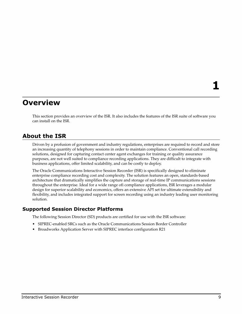
Logging Into ISR DashboardUse the following procedures to verify the administrator dashboard is working properly.
To log into the Dashboard:
1. Open your Internet Web browser.2. Enter the IP address of the ISR Dashboard. For example:
https://172.54.66.7The initial Login page displays.
3. Enter your email and password respectively, in the Email and Password fields.The initial temporary user name and password are:
User name: [email protected] Password: admin123.
Note: You are required to change the default email and password upon initial login and then thepassword again every 90 days.
4. After logging in, the following page displays.
Navigation Icons
The ISR Dashboard provides specific navigation tools you can use to perform functions when required.The following table identifies these tools.
Icon Description
Add - Adds an item to the list.
Delete - Removes the item from the list.
Post-Install Verification and Configuration
26 Interactive Session Recorder

Icon Description
Details - Shows additional information about the item.
Back - Navigates to the previous screen.
Forward - Navigates to the next screen.
Play - Plays the file.
Download - Downloads the selected recording to your PC or local server.
User Audit Trail - Display the selected user’s audit trail (Action performed,time, IP address, etc.)
RSS Details - Displays and allows you to edit RSS details and advancedconfiguration information about a Site.
Enabled - Status that indicates the element is enabled or active.
Disabled - Status that indicates the element is disabled or inactive.
Error - Status that indicates an error occurred on the element.
Help - Displays information about online Technical Support.
Logoff - Exits from the ISR Dashboard.
For more information about using the features and functions of the ISR dashboard, see the InteractiveSession Recorder Administrator Guide or the Interactive Session Recorder User Guide.
Before you can make the first call, you must configure the RSS and the route to use to receive the call. Usethe procedures in Configuring the ISR for Recording a Call to configure the RSS and route.
Configuring the ISR for Recording a CallYou can place a call to verify that the ISR call recording functionality is working properly. Before you canplace a call, you must configure the following on the ISR:
• Add a new site for the RSS server• Add a new RSS to the site• Add a Route
Add Site for RSS ServerTo verify that the RSS and the dashboard are communicating, you must add a new site for the RSS server.Use the following procedure to add a new site.
To add a site:
1. From the Main Menu, click Admin.2. Click Sites.3. Click Create.4. In the Name field, enter a name for the Site and click Create. The new site displays on the Sites page.
Post-Install Verification and Configuration
Interactive Session Recorder 27

For more information about creating Sites, see the Oracle Communications Interactive Session RecorderAdministrator Guide.
Add the RSS to a SiteTo enable connectivity between the RSS and the CIS, you must add the new RSS to a site. Use the followingprocedure to add the new RSS.
To add the new RSS to the site:
1. On the All Sites page, select a site for which you want to add the RSS, and click .
The following page displays.
The RSS block displays the following:
Field Description
Running
Displays the number of RSSs currently enabled (active.)
Running with errors
Displays the number of RSSs currently active with errors.
Not running (or could notconnect to)
Displays the number of RSSs currently disabled (inactive).
Total ports in use Displays the total number of RSS ports currently in use.
Total ports Displays the total number of licensed ports.
2. Click the RSS block. The following page displays.
Post-Install Verification and Configuration
28 Interactive Session Recorder

The RSS page displays the following about each RSS.
Column Description
Name Name of the RSS.
VoIP IP IP Address of the VoIP interface of the RSS.
Status Current status of the RSS . Status can be:
Enabled (active)
Disabled (inactive)
Active with errors
Uptime Time elapsed since the last RSS process restart.
Current Sessions in Use Total number of ports currently being used on the RSS.
Sessions Capacity Total number of licensed ports on the RSS.
3. Click Create. The following dialog box displays.
4. In the Name field, enter a name for the RSS you are adding.5. In the VoIP IP field, enter the IP address (in dotted decimal format) on which the RSS is listening for
SIP traffic.6. In the Admin IP field, enter the IP address at which to connect to the RSS host over the Administrator
network.7. In the Data IP field, enter the IP address at which ISR components communicate with the RSS host over
the Data network.
Post-Install Verification and Configuration
Interactive Session Recorder 29

8. In the Sessions Capacity field, enter the value of the number of concurrent sessions allowed for thisRSS host.
Note: This number must comply with your Oracle contract.
9. Click Create.For additional information about RSS, see the Interactive Session Recorder Administrator Guide.
Post-Install Verification and Configuration
30 Interactive Session Recorder

5Setting up a Test Call
This chapter provides information and procedures for configuring the first route to use for placing a testcall to the ISR. It also includes information for setting up a Softphone for making the first call proceduresfor verifying that the recording was made and that the Dashboard works properly.
Configuring a RouteRoute configuration is important to the flexibility of your ISR installation. A route defines the parametersto evaluate and invoke recording, as well as the recording rules to apply for all calls received by the ISR.Users are given access to recordings based on routes.
Use the following test procedure to make your first recording. This procedure uses a wildcard route thatapplies the same recording rules to every call received. Please note that this is not the recommendedconfiguration to deploy in a production system, as it eliminates the ability to assign users access to specificrecordings.
Note: Use the new Route you configure in this section for call verification purposes only.
To configure a route:
1. Open your Internet Web browser.2. Enter the IP address of the ISR. For example:
https://172.54.66.7The Login page displays.
3. Enter your email and password, respectively, in the "Email" and Password fields.
Note: Upon initial login, you are required to change the email and password login credentials, and thenyou must update the password again every 90 days.
Interactive Session Recorder 31

The following page displays.
4. From the Main Menu, click Admin. The following page displays.
5. Click the Routes . The following page displays.
The Route page displays the following about each Route.
Column Description
Account Name of the Account assigned to the current route.
Type Type of route associated with this account (DNIS - To, ANI - From, orBoth - To/From)
Pattern Pattern that is matched in the incoming INVITE.
Virtual Pattern The user portion of the destination where the calls matching the routepattern are forwarded once recording rules have been evaluated.
Record Specifies whether or not recording is enabled on this account/route.
Setting up a Test Call
32 Interactive Session Recorder
Column Description
Recording is enabled
Recording is disabled
Percent to Record Indicates the percentage of calls currently being recorded on thisaccount/route.
This route can also be used to test SIPREC traffic without any changes.
Setting Up a SoftphoneIn order to make calls to the RSS, you must have phone hardware or a softphone. If you have phonehardware with a configured route to the ISR, you can skip the procedure in this section and go directly tothe procedure Verifying Call Recording/Playback Using the Dashboard to verify connectivity to the RSS.
A softphone is software that allows you to talk using VoIP without having a physical phone set. It acts asan interface allowing you to dial numbers and carry out other phone functions using your computer screenand your mouse, keyboard or keypad.
If you would like to make a call to the RSS using a softphone, use the procedures in this section to install aSIP Softphone onto your computer. You can use any SIP Softphone application that supports G.711a/u.The following example installs the PhonerLite SIP Softphone application.
Installing the SoftphoneUse the following procedure to install the Softphone.
To install the softphone:
Note: You must install the Softphone onto a computer with network access to the RSS server andthe computer must have audio input/output (microphone/speakers).
1. Open a Web browser and enter the following URL in the URL field to access the download page for thePhonerLite application: http://www.phonerlite.de/download_en.htm
2. Click on the PhonerLiteSetup.exe file in the download box to download the application to your PC.3. Double-click the application and follow the instructions to install PhonerLite to your PC.
Configuring the SoftphoneUse the following procedure to configure the Softphone.
To configure the softphone:
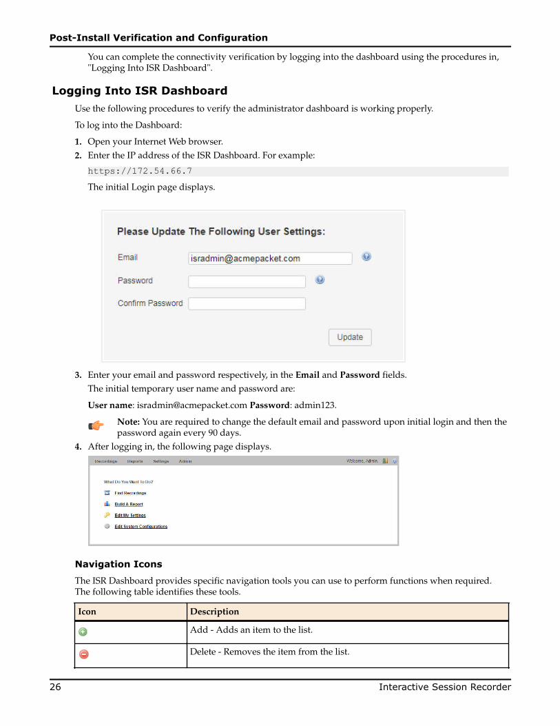
1. When PhonerLite is installed, double-click the PhonerLite icon on your desktop to open the application.
2. In the PhonerLite window, click the Configuration tab.3. Click the Server tab.
Setting up a Test Call
Interactive Session Recorder 33

4. Verify that the Register box is disabled (unchecked).5. Click the User tab.
6. In the User name box, enter your user name. Your user name is your outgoing caller ID (SIP URI).7. In the Displayed name box, enter a name to display to the recipient of a call. Valid values are alpha-
numerical characters.8. Click on the Network tab.
9. In the Local Port box, enter the value for an open port on your computer. Default SIP port is 5060. Thisport value should be available if you have no other SIP devices running on your computer.
10. In the Preferred connection type field, click UDP to enable it. The RSS requires the UDP transportprotocol. All other network parameters can remain at default values.
Setting up a Test Call
34 Interactive Session Recorder

11. Click the Codecs tab.
12. In the codec list, select "G.711 A-Law, 64 kbps" and/or G.711 u-Law, 64 kbps. At least one of thesecodecs must be selected.
13. In the drop-down box, select blank silence packets.14. Click the <Save> icon. Do not close this Softphone application as you will be using it to make your first
call. Go to Making the First Call to make the first test call to the RSS.
Making the First CallAfter installing the Softphone Client, you can use it to place your first call to the RSS.
Before You BeginBefore you make your first call to the RSS, open the /opt/isr/logs/recorder/recorder.log file to observethe cache refresh and see your test call display in the log as it happens.
To open the ISR.log file:
1. Enter tail -f /opt/isr/logs/recorder/recorder.log and press Enter.
<hostname> # tail -f /opt/isr/logs/recorder/recorder.log2. In your Softphone client (PhonerLite), enter a test phone number in the "Destination Number" field.
The destination number must be a full SIP URI of the format sip:<User>@<your_rss_ip>. The followingwindow uses an example destination number of sip:[email protected].
Setting up a Test Call
Interactive Session Recorder 35

3.Click the icon in the Main Menu or Press Enter.The output in the /opt/isr/logs/recorder/recorder.log displayed in your RSS tail should look similarto the following:
08/30/2011 07:31:54[ INFO] sipProxy: (SIP INVITE received - new call!!! [cid = 1, did = 2]) 08/30/2011 07:31:54[ INFO] sipProxy: [Channel 1] Looking up call w/ ANI: 7818692818 DNIS: test 08/30/2011 07:31:54[ INFO]callManager: [Channel 1] Enqueueing SipCall, callId: [email protected] 08/30/2011 07:31:54[ INFO]callManager: [Channel 1] Dequeueing SipCall, callId: [email protected], queueSize: 1 08/30/2011 07:31:54[ INFO]callManager: [Channel 1] Looking up call w/ ANI: 7818692818 DNIS: test 08/30/2011 07:31:54[ INFO] RouteMap: Call route with ANI:7818692818 DNIS: test returned CALL_TYPE_CONFERENCE accountName: System 08/30/2011 07:31:54[ INFO] RouteMap: [Channel 1] getRouteInfo returned with vDNIS: test, isRecordable: true 08/30/2011 07:31:54[ INFO]xmlRpcQueryAgent: XmlRpcQueryAgent::execute: method addDirectVmgEntry (_connectionState 0). 08/30/2011 07:31:54[ INFO]xmlRpcQueryAgent: XmlRpcQueryAgent::execute: method addDirectVmgEntry completed. 08/30/2011 07:31:54[ INFO]callManager: [Channel 1] addDirectVmgEntry return with ACK. 08/30/2011 07:31:54[ INFO]callManager: [Channel 1] addDirectVmgEntry is successful with ANI: 7818692818 DNIS: test channelId 1 08/30/2011 07:31:54[ INFO]callManager: [Channel 1] routeId 1 adjusted limit is 24, adjusted burst ports is 6, acct limit is 100, acct burst port is -1. 08/30/2011 07:31:54[ INFO]callManager: [Channel 1] Current route (1) usage: 1, account (1) usage: 1. 08/30/2011 07:31:54[ INFO] sipProxy: [Channel 1] Call State Transition: Idle -> Called
Setting up a Test Call
36 Interactive Session Recorder

08/30/2011 07:31:54[ INFO] sipProxy: [Channel 1] Got rtp port 22000 for Caller->Mixer RTP Stream. 08/30/2011 07:31:54[ INFO] sipProxy: [Channel 1] Got RTP Port 22002 for 3Party->Mixer RTP Stream.
4. When the RSS answers the call, leave a voice recording.5.
Click to hang up the phone.6. Verify that no errors appear in the ISR.log file on your RSS tail output. Go to Verifying Call Recording/
Playback Using the Dashboard to verify the call recording was successful.
Verifying Call Recording/Playback Using the DashboardAfter making a call with your phone equipment or softphone, you can verify that the call recording wassuccessful by playing back the call using the ISR Dashboard. Use this procedure to verify that the RSS hasstored your recording.
Note: Before playing recordings, make sure you have a media application that plays audio fileswith a .wav format and that your speaker/microphone is turned ON. For more information aboutthe software requirements and recommendations for playing recordings, see ISR DashboardRequirements.
To verify the call recording/playback:
From the Main Menu, click Recordings. The following page displays.
This page displays the test recording you just made on the first call to the RSS.
Select the recording and click the Play icon. Your media application opens and plays the file for you tolisten. If you can hear the recording, the call recording process was successful.
If required, you can also view the details of the recording by clicking the Details icon on the recordingspage. This displays details about the recording and allows you to select the Play icon at the top of thepage to play the recording from the details page.
If the recording does not appear in the dashboard, review your ISR log for errors.
If the recording appears in the dashboard but does not play, ensure your media application is installed.Dashboard logging can be found on the dashboard VM in /opt/isr/logs/dashboard/production.log.
Setting up a Test Call
Interactive Session Recorder 37


6Deploying and Configuring the Remote ArchivalWeb Service
Deploying the ISR Remote Archival Web ServiceThe ISR Remote Archival Web Service (RAWS) is deployed the same way as the other ISR components. Formore information, see Installing the ISR Index in the Oracle Communications Interactive Session RecorderInstallation Guide.
Installing the Remote Archival Web ServiceThis section describes how to install the ISR Remote Archival Web Service (RAWS).
Note: During the installation process, you will be asked to provide and/or verify the users,passwords, and interfaces you created during the Oracle Linux installation.
To install the ISR RAWS:
1. Log into the Oracle Linux CLI using an SSH client.
Note: The Oracle Linux CLI is case-sensitive.
2. Enter the following command into the CLI:
sudo yum install isr-RemoteArchivalNote: Most ISR installation environments do not have access to a repository with the RPMrequired to install the isr-RemoteArchival RPM itself. The simplest way to manage this issue isto (secure) copy the following files onto the Index host:
• isr-RemoteArchival-5.2-0.x86_64.rpm
Once the files are properly copied, connect to the Index host with an SSH client and in thedirectory (for example, /tmp) containing the files, execute the following two commands:
# sudo yum localinstall /tmp/isr-RemoteArchival-5.2-0.x86_64.rpm3. Verify the installation when prompted.
Is this ok [y/d/N]:Oracle Linux downloads the RAWS installation packages.
Interactive Session Recorder 39

4. Enter the following command into the CLI once Oracle Linux indicates the installation packages havefinished downloading.
sudo /opt/isr/configIsr.shNote: Once you begin editing the configIsr.sh script, you cannot perform a <Ctrl> C to exit thefile.
5. Follow the script's instructions closely.
• Create a certificate key password when prompted.
Note: This password does not have to follow any rigid requirements.
• When prompted for Database IP addresses, you may press <Enter> to accept the default values,unless you are not using the default Index IP address of the Local network. In that case, enter theappropriate values.
• Map the physical network interfaces to ISR networks. Hit <Enter> when prompted.
System Interfaces Found:ens32 ens33-1 ens34 ens36
Enter Admin interface [ens32] <Enter>Enter Local Interface [ens33-1] <Enter>Enter VoIP Interface [ens34] <Enter>Enter Data Interface [ens36] <Enter>
• Select m when prompted to set the hostname and finish the configuration.
Please select from the following menu:--------------------------------------------
s) Show the current configurationm) Modify the current configurationi) Modify network interface mappingz) Show firewall settings for Remote Archival.q) Quit
Choice: m• The RAWS MySQL user must be granted access to the Index database and only can once the
network connectivity is established. If networking is not properly configured before the MySQL userstep, the following error and instruction are displayed:
Networking connection to MySQL index not available, please configure networking and run the configuration option 'm' again. Hit <Enter> when ready. Once you've chosen m to modify the configuration, accept the prompt to add the Remote Archival/RAWS MySQL user and follow the steps carefully to grant privileges.
The ISR Remote Archiver is installed.
Deploying and Configuring the Remote Archival Web Service
40 Interactive Session Recorder

7Deploying and Configuring ISR FACE
Deploying ISR FACEThe ISR FACE is deployed the same way as the other ISR components. The ISR FACE is commonlydeployed on an Oracle Linux 7 VM and has the same prerequisites as the other ISR components.
Installing ISR FACEBy default, FACE is configured to handle HTTP requests over SSL, but you must perform the followingsteps to complete the initial configuration.
Note: During the installation process, you will be asked to provide and/or verify the users,passwords, and interfaces you created during the Oracle Linux installation.
To install the ISR FACE:
1. Log into the Oracle Linux CLI using an SSH client.
Note: The Oracle Linux CLI is case-sensitive.
2. Enter the following command into the CLI:
sudo yum install isr-FaceNote: Most ISR installation environments do not have access to a repository with the RPMrequired to install the isr-Face RPM itself. The simplest way to manage this issue is to (secure)copy the following file onto the Index host:
• isr-Face-<release#>.x86_64.rpm
Once the file is properly copied, connect to the Index host with an SSH client and in thedirectory (for example, /tmp) containing the file, execute the following command:
# sudo yum localinstall /tmp/isr-Face-<release#>.x86_64.rpm3. Verify the installation when prompted.
Is this ok [y/d/N]:Oracle Linux downloads the FACE installation packages.
4. Enter the following command into the CLI once Oracle Linux indicates the installation packages havefinished downloading.
sudo /opt/isr/configIsr.sh
Interactive Session Recorder 41

5. Follow the script's instructions closely.
• Create a certificate key password when prompted.
Note: This password does not have to follow any rigid requirements.
• When prompted for Database IP addresses, you may press <Enter> to accept the default values,unless you are not using the default Index IP address of the Local network. In that case, enter theappropriate values.
• Select m when prompted to set the hostname and finish the configuration.
Please select from the following menu:--------------------------------------------
s) Show the current configurationm) Modify the current configurationi) Modify network interface mappingz) Show firewall settings for Index.q) Quit
Choice: mThe ISR FACE is installed.
Configuring FACE Reduced SecurityThe ISR's FACE functionality may be run with reduced security. You can use the configCis.sh script toloosen security settings on the FACE host.
To disable HTTPS in FACE, run the configCis.sh script and select HTTP for FACE.
[root@face ~]# configCis.sh--------------------------------------------Please select from the following menu:--------------------------------------------
s) Show the current configurationm) Modify the current configurationi) Add/modify a second network interfacef) Set face default configuration in DBq) Quit
Choice: f
WARNING, this action will reset the FACE to its default configuration. ** All customization of FACE or EEN configured will be lost.
Continue? (yes|no) [yes] yesYou have been warned.
Enter Face Host IP: [] 1.2.3.4Protocol to use for FACE connections? (http|https) [https] http
FACE connection protocol set to httpEnter ObserveIT Server IP: [] 2.3.4.5Protocol to use for ObserveIT Server connections? (http|https) [https]ObserveIT connection protocol set to httpsAttempting to restore backup SQLBacking up FACE Config (to /opt/isr/faceSetupTemplate.sql.bak).Updating FACE IP in SQL Script.Updating FACE HTTP/S in SQL Script.Updating ObserveIT IP in SQL Script.
Deploying and Configuring ISR FACE
42 Interactive Session Recorder

8Upgrading the ISR
The ISR includes a "yum-style" approach to upgrading all ISR applications on each ISR component host.The upgrade feature is limited to upgrades within the 5.2Mx and later release sets, and an upgrade processfrom release 5.1 or earlier is not currently available. Contact your Oracle account representative with anyquestions.
You must upgrade the ISR components in the following order:
• Index• RSS• Dashboard• FACE (if present)
Note: The order in which you must upgrade ISR components has changed from 5.x releases.
Upgrade PrerequisitesTo upgrade the ISR components, you must complete the following prerequisites:
• The ISR component hosts are properly running on the Oracle Linux 7.2 OS• Access to the following upgrade tar files from the ISR component hosts:
• isr-Index-<release#>-upgrade.tgz• isr-Dashboard-<release#>-upgrade.tgz• isr-rss-<release#>-upgrade.tgz• isr-Face-<release#>-upgrade.tgz
• Have access to the Ruby 2.4 rpm ( ruby-2.4.0-1.el7.centos.x86_64.rpm )• For the duration of the maintenance window, all call traffic is stopped on all sites and outside client
access to the Dashboard and API services, is prohibited.
Note: The following instructions assume the recommended "isradm" Linux user has sudopermissions.
WARNING: The upgrade process for each component includes a critical backup step that copies importanthost configuration, ISR application configuration, ISR application platform configuration, ISR applicationdata, encrypted keys, keystores, and log files to a temporary directory before consolidating these copiesinto a compressed set of files for a potential rollback situation. This backup step requires additional diskspace to successfully write the files, and a warning prompt is displayed to detail concerns and recommend
Interactive Session Recorder 43
an option to mount an additional drive if disk space may be an issue. Oracle strongly recommends youconsider these details and the recommended option carefully before continuing with the upgrade. Formore information about mounting remote storage, see Chapter 22, Shared File System Administration fromthe Oracle Linux Administrators Guide Release 7.
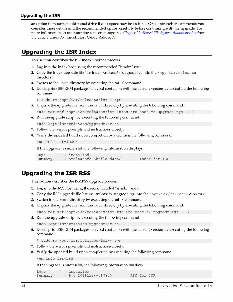
Upgrading the ISR IndexThis section describes the ISR Index upgrade process.
1. Log into the Index host using the recommended "isradm" user.2. Copy the Index upgrade file "isr-Index-<release#>-upgrade.tgz into the /opt/isr/releases
directory.3. Switch to the root directory by executing the cd / command.
4. Delete prior ISR RPM packages to avoid confusion with the current version by executing the followingcommand:
$ sudo rm /opt/isr/releases/isr-*.rpm5. Unpack the upgrade file from the root directory by executing the following command:
sudo tar xzf /opt/isr/releases/isr-Index-<release #>-upgrade.tgz -C /6. Run the upgrade script by executing the following command:
sudo /opt/isr/releases/upgradeIsr.sh7. Follow the script's prompts and instructions closely.8. Verify the updated build upon completion by executing the following command.
yum info isr-IndexIf the upgrade is successful, the following information displays:
Repo : installedSummary : <release#> <build_date> Index for ISR
Upgrading the ISR RSSThis section describes the ISR RSS upgrade process.
1. Log into the RSS host using the recommended "isradm" user.2. Copy the RSS upgrade file "isr-rss-<release#>-upgrade.tgz into the /opt/isr/releases directory.
3. Switch to the root directory by executing the cd / command.
4. Unpack the upgrade file from the root directory by executing the following command:
sudo tar xzf /opt/isr/releases/isr-rss-<release #>-upgrade.tgz -C /5. Run the upgrade script by executing the following command:
sudo /opt/isr/releases/upgradeIsr.sh6. Delete prior ISR RPM packages to avoid confusion with the current version by executing the following
command:
$ sudo rm /opt/isr/releases/isr-*.rpm7. Follow the script's prompts and instructions closely.8. Verify the updated build upon completion by executing the following command.
yum info isr-rssIf the upgrade is successful, the following information displays.
Repo : installedSummary : 6.0 20161234-567890 RSS for ISR
Upgrading the ISR
44 Interactive Session Recorder

9. Run the configuration script by executing the following command:
sudo /opt/isr/configIsr.sh10. Follow any configuration script's prompts and instructions closely to ensure all component
configurations are verified and select the q option to finish.
Upgrading the ISR DashboardThis section describes the ISR Dashboard upgrade process.
1. Log into the Dashboard host using the recommended "isradm" user.2. Copy the Dashboard upgrade file "isr-Dashboard-<release#>-upgrade.tgz into the /opt/isr/
releases directory.
3. Copy the Ruby 2.4 RPM to the /opt/isr/releases directory. The Ruby 2.4 RPM package is easilyobtained from GitHub here: https://github.com/feedforce/ruby-rpm/releases/tag/2.4.0 with the file name"ruby-2.4.0-1.el7.centos.x86_64.rpm".
4. Switch to the root directory by executing the cd / command.
5. Delete prior ISR RPM packages to avoid confusion with the current version by executing the followingcommand:
$ sudo rm /opt/isr/releases/isr-*.rpm6. Unpack the upgrade file from the root directory by executing the following command:
sudo tar xzf /opt/isr/releases/isr-Dashboard-<release #>-upgrade.tgz -C /7. Run the upgrade script by executing the following command:
sudo /opt/isr/releases/upgradeIsr.sh8. Follow the script's prompts and instructions closely.9. Verify the updated build upon completion by executing the following command.
yum info isr-DashboardIf the upgrade is successful, the following information displays:
Repo : installedSummary : <release#> <build_date> Dashboard for ISR
10. Run the configuration script with the following command:
sudo /opt/isr/configIsr.sh11. Follow the configuration script's prompts and instructions closely to import public keys from all RSS
hosts.
Note: For the Recorder and Converter processes to update their configurations and recordsuccessfully after upgrade, you must log into the Dashboard, access the Admin > Sites >Recorders page, and edit each Recorder, updating their network IPs, Sessions Capacity, Primaryand Failover Locations, and confirm the remaining configuration settings. The Primary Locationmay already be set. Typically, the Failover Location is configured to the Destination Location setfor the Archival process for this Recorder.
Upgrading the ISR FACEThis section describes the ISR FACE upgrade process.
1. Log into the FACE host using the recommended "isradm" user.2. Copy the FACE upgrade file "isr-Face-<release#>-upgrade.tgz into the /opt/isr/releases directory.
3. Switch to the root directory by executing the cd / command.
Upgrading the ISR
Interactive Session Recorder 45

4. Delete prior ISR RPM packages to avoid confusion with the current version by executing the followingcommand:
$ sudo rm /opt/isr/releases/isr-*.rpm5. Unpack the upgrade file from the root directory by executing the following command:
sudo tar xzf /opt/isr/releases/isr-Face-<release #>-upgrade.tgz -C /6. Run the upgrade script by executing the following command:
sudo /opt/isr/releases/upgradeIsr.sh7. Follow the script's prompts and instructions closely.8. Verify the updated build upon completion by executing the following command.
yum info isr-FaceIf the upgrade is successful, the following information displays:
Repo : installedSummary : <release#> <build_date> Face for ISR
9. Run the configuration script with the following command:
sudo /opt/isr/configIsr.sh10. Follow the configuration script's prompts and instructions closely to import public keys from all RSS
hosts.
Upgrading the ISR
46 Interactive Session Recorder

AInstalling a Virtual Machine
This section describes the process of installing a VM.
Configuring a VMware Enterprise vSphere Hypervisor (ESXi)
What is vSphere Hypervisor?The vSphere Hypervisor (formerly known as ESXi), is the free edition of vSphere offering the bare-metalarchitecture for best possible performance. It installs during boot-time of the Hypervisor host.
The following components traditionally run on the Hypervisor platform:
• Index - MySQL Server stores the recording and management data• Dashboard - Single ISR Dashboard for both the Administrator and User• FACE
Virtual Machine Default Resource Configurations
The ISR supports one platform, the VMWare vSphere Hypervisor. Any Hypervisor that Supports OracleLinux 7.2 and higher are permitted.
Note: A table on the VMWare Knowledge Base recommends certain VM virtual hardware versions(“VM Version” above) with Hypervisor (ESXi) platform versions. Although no misbehaviorassociated with the ISR hosts has been confirmed as related to hardware version incompatibilities,the latest virtual hardware version, vmx-10, has been successfully tested with the recommendedHypervisor version, VMware ESXi 5.5 Update 2. The following instructions from VMWare’sKnowledge Base explain upgrading the virtual hardware version of a VM:
1. Power on the VM to be upgraded.2. Install VMware Tools using vSphere client by right-clicking on the VM, selecting the Guest
menu, and the Install/Upgrade VMWare Tools option.3. In vSphere client, right-click the entry for the VM and select Upgrade Virtual Hardware.4. In vSphere Client’s General Summary of the VM confirm the VM Version value is vmx-10.5. Power on the VM.
Installing vSphere HypervisorUse the following procedure to install vSphere Hypervisor. Before beginning this installation, be sure youhave performed the tasks in the section Before You Begin.
Interactive Session Recorder 47

To install vSphere Hypervisor:
1. Open a web browser and enter the following URL to navigate to the VMware download page:
https://my.vmware.com/web/vmware/evalcenter?p=free-esxi5&lp=default2. Download the ESXi 5.5 update 1 file to your server.
Note: You may need to login into the VMware download page with a user name and passwordbefore downloading the file. If not already registered, please register and then login todownload the applicable file.
3. Burn the ESXi 5.5 update 1 <filename>.ISO image to a CD.4. Boot the server from the ESXi 5.5 update 1 CD you just created.5. At the prompt, press Enter to proceed with the installation.6. Press <F11> to accept the ESXi 5.5 license.7. At the Select a Disk menu, press Enter to confirm the remote storage device and continue.8. Press <F11> to install the ESXi 5.5 update 1.9. When the installation is complete, remove the CD and press Enter to reboot the server.10. Configure the vSphere Hypervisor using the procedures in Configuring vSphere Hypervisor.
Configuring vSphere HypervisorAfter installing the vSphere Hypervisor, you must perform two basic configuration step before you can useit. Use the following procedure to configure vSphere Hypervisor.
To deploy your Oracle Linux 7 Virtual Machines:
1. After installing vSphere Hypervisor and rebooting the server, press <F2> Customize System.2. At the login prompt, enter the following:
User name: rootPassword: <leave blank>
3. Select Configure Password and follow the instructions to assign a password to assign for logging intovSphere Hypervisor.
The password rules as stated on the VMWare knowledge base are as follows:
A valid password requires a mix of upper and lower case letters,digits, and other characters. You can use a 7-character long passwordwith characters from at least 3 of these 4 classes, or a 6-character longpassword containing characters from all the classes. An upper caseletter that begins the password and a digit that ends it do not counttowards the number of character classes used. It is recommended thatthe password does not contain the username.
Warning: This password is required to login to your Hypervisor instance (this console) as wellas for accessing through the vSphere client.
Keep this password secure.4. Press Enter when complete to enter the System Customization Menu.5. Select Configure Management Network and press Enter.6. Select Network Adapters and confirm at least one network interface card (NIC) has status showing
"Connected". Press Enter.
Note: Make a note of this NIC; you will need this information later.
7. Select IP Configuration and press Enter.8. Press <space bar> to select Set Static IP Address and Network Configuration.
Installing a Virtual Machine
48 Interactive Session Recorder

9. Enter the IP address of your ESXi Host and press Enter.For example, IP Address: 172.40.34.56
10. Enter the subnet mask and press Enter.For example, Subnet Mask: 255.255.255.0
11. Enter the default gateway and press Enter.For example, Default Gateway: 172.40.34.1
12. Press <Esc> to exit the IP Configuration Menu.13. Select DNS Configuration.14. In the DNS Server field, specify the domain name system (DNS) server addresses if required.
Note: Internet access is required to download the vSphere Client in the next section.
15. In the Hostname field, specify the Hostname for the server to use.16. Press <Esc> to exit the DNS Configuration Menu.17. Press <Esc> to exit the Management Network Menu.18. At the Save Changes prompt, press Y to apply the changes and restart the management network.19. Select Test Management Network.20. Attempt to ping your server in the network.
Note: The ping you send out may include any DNS server configured in your network.
If the first attempt fails, try pinging again. The test should show a response from your server indicatingthat your server was setup correctly for network management in your network.
Note: If your hostname cannot be resolved by your DNS servers, or you didn’t configure anyDNS servers, the resolving hostname test will fail. This does not adversely affect the CISperformance.
21. Press <Esc> to exit the Test Management Network Menu.22. Press <Esc> to log out.
Once the ESXi host is on the network, perform all configuration management through the vSphareclient.
VMware vSphere Client
What is vSphere Client?The vSphere Client is an application that enables management of a vSphere installation. The vSphereClient provides an administrator with access to the key functions of vSphere without the need to access avSphere server directly.
Installing vSphere ClientAfter installing the vSphere Hypervisor onto your server, you can then install the vSphere Client onto yourMicrosoft Windows® machine. Installing the vSphere Client, includes:
• Downloading the vSphere Client from VMware• Assigning a License to VMware vSphere Hypervisor• Assigning the network time servers• Adding additional virtual network
To install the vSphere Client:
Installing a Virtual Machine
Interactive Session Recorder 49
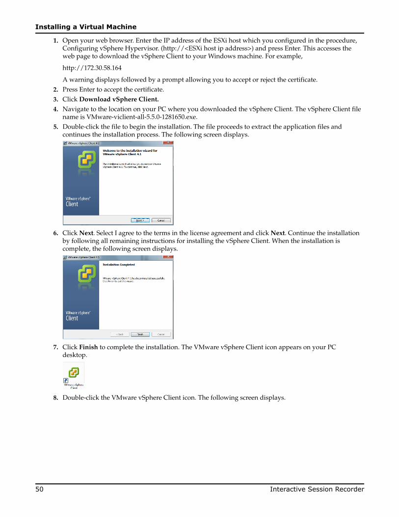
1. Open your web browser. Enter the IP address of the ESXi host which you configured in the procedure,Configuring vSphere Hypervisor. (http://<ESXi host ip address>) and press Enter. This accesses theweb page to download the vSphere Client to your Windows machine. For example,
http://172.30.58.164
A warning displays followed by a prompt allowing you to accept or reject the certificate.2. Press Enter to accept the certificate.3. Click Download vSphere Client.
4. Navigate to the location on your PC where you downloaded the vSphere Client. The vSphere Client filename is VMware-viclient-all-5.5.0-1281650.exe.
5. Double-click the file to begin the installation. The file proceeds to extract the application files andcontinues the installation process. The following screen displays.
6. Click Next. Select I agree to the terms in the license agreement and click Next. Continue the installationby following all remaining instructions for installing the vSphere Client. When the installation iscomplete, the following screen displays.
7. Click Finish to complete the installation. The VMware vSphere Client icon appears on your PCdesktop.
8. Double-click the VMware vSphere Client icon. The following screen displays.
Installing a Virtual Machine
50 Interactive Session Recorder

9. In the IP address / Name text box, enter the IP address or the domain name of the ESXi host. Forexample:
IP address / Name: 172.30.58.164
10. In the User name text box, enter the user name assigned to you by the system administrator of the ESXihost. For example:
User name: root
11. In the Password text box, enter the password assigned to you by the system administrator of the ESXihost. For example:
Password: jre453i
12. Click Login. The following Security Warning displays:
13. Place a check mark in the box that indicates: Install this certificate and do not display any securitywarnings for <ip_address>. The IP address is the address of the ESXi host.
14. Press Ignore. The VMware Evaluation Notice alert displays.15. Click "Assign license to the ESXi host."
Note: vSphere 4 Hypervisor is licensed for 2 physical CPUs (free, never expires).
Getting the vSphere Hypervisor LicenseTo get the VMware vSphere Hypervisor License:
1. Enter the following URL:https://www.vmware.com/account/login.do
2. Register for a VMware account by clicking Register. Or if already registered, enter your email addressor VMware customer number, and password, and click Sign In.
VMware sends the following message to the email address you specified during registration:
Thank you for creating a VMware account. To complete the registration process, please click the buttonbelow.
3. Open your email message from VMware and click the Activate Now button.The VMware ‘s Enter Your Password screen displays.
4. In the Password text box, enter the password you specified when registering with VMware and clickContinue.
Installing a Virtual Machine
Interactive Session Recorder 51

The "Account Activated" screen displays with the following message:
Success! Your account has been activated.5. Copy and paste the following link into your browser:
https://my.vmware.com/web/vmware/evalcenter?p=free-esxi5&lp=default&lp=1&ie=UTF-8&q=vmware%20vsphere%20hypervisor%20esxi%204.1%20license
6. In the box, On how many physical servers do you plan to install VMware vSphere Hypervisor?, enterthe number of servers on which you are installing the VMware vSphere Hypervisor.Valid values are 1 - 999.
7. Place a check mark in the box, I agree to the terms and conditions outlined in the VMware vSphereHypervisor End User License Agreement. and click Register.VMware sends you an email message for accessing your VMware ESXi License.
8. Open your email message from VMware and click Access Now.A VMware vSphere Hypervisor license string displays.
9. Copy the VMware vSphere Hypervisor license key string.
Applying the VMware vSphere Hypervisor LicenseTo apply the VMware vSphere Hypervisor license:
1. Click OK to close the VMware Evaluation Notice window that displayed in Step 14. The followingwindow displays. The ESXi Host IP displays in the left column.
2. Click the Configuration tab.3. In the left column, under the Software category, click Licensed Features.4. In the upper right corner of the window, click Edit. The following window displays.
Installing a Virtual Machine
52 Interactive Session Recorder
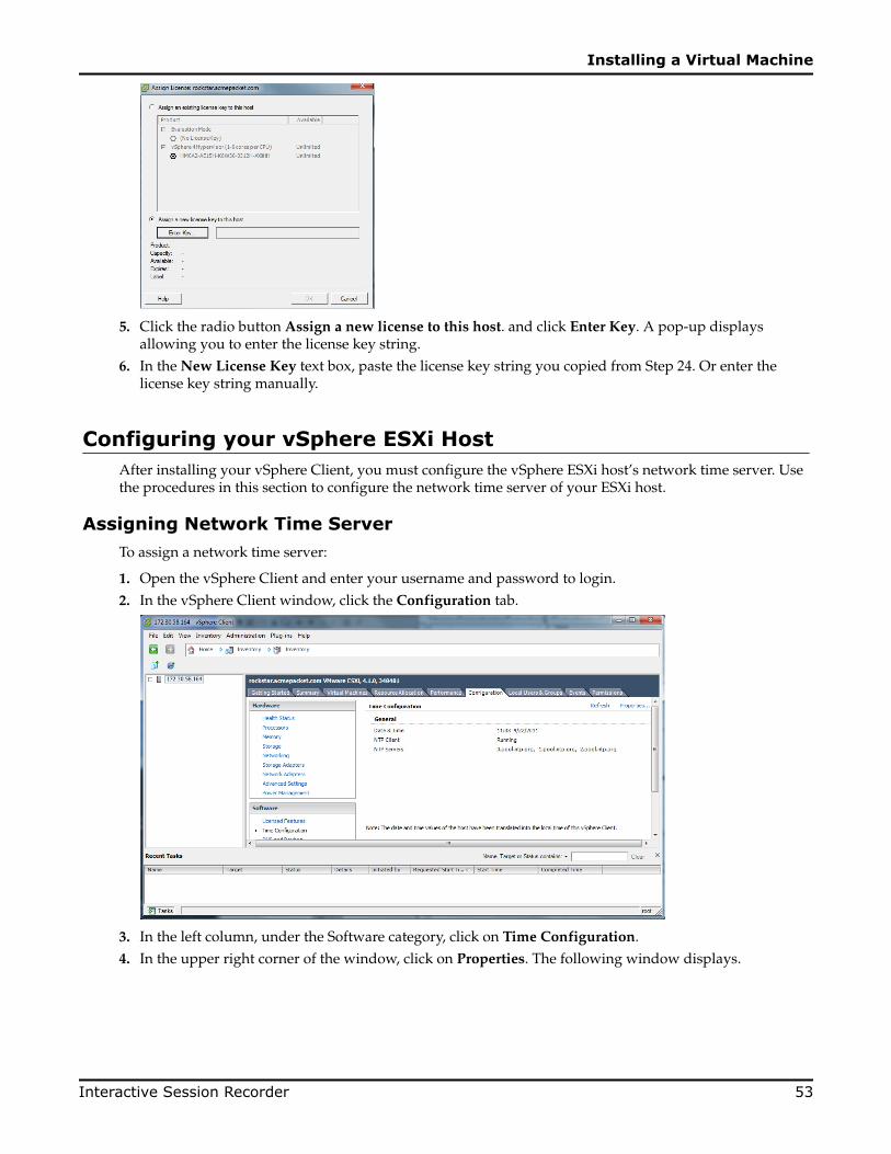
5. Click the radio button Assign a new license to this host. and click Enter Key. A pop-up displaysallowing you to enter the license key string.
6. In the New License Key text box, paste the license key string you copied from Step 24. Or enter thelicense key string manually.
Configuring your vSphere ESXi HostAfter installing your vSphere Client, you must configure the vSphere ESXi host’s network time server. Usethe procedures in this section to configure the network time server of your ESXi host.
Assigning Network Time ServerTo assign a network time server:
1. Open the vSphere Client and enter your username and password to login.2. In the vSphere Client window, click the Configuration tab.
3. In the left column, under the Software category, click on Time Configuration.4. In the upper right corner of the window, click on Properties. The following window displays.
Installing a Virtual Machine
Interactive Session Recorder 53

5. Click on Options. The following window displays.
6. In the left column, click on NTP Settnigs.7. Click Add. The following window displays.
8. Add each of the following in the Address text box, clicking OK after each entry:
• 0.pool.ntp.org• 1.pool.ntp.org• 2.pool.ntp.org
The entries display in the NTP Servers box.
9. In the left column, click on General. The following window displays.
Installing a Virtual Machine
54 Interactive Session Recorder
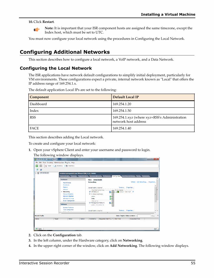
10. Click Restart.
Note: It is important that your ISR component hosts are assigned the same timezone, except theIndex host, which must be set to UTC.
You must now configure your local network using the procedures in Configuring the Local Network.
Configuring Additional NetworksThis section describes how to configure a local network, a VoIP network, and a Data Network.
Configuring the Local NetworkThe ISR applications have network default configurations to simplify initial deployment, particularly forVM environments. These configurations expect a private, internal network known as "Local" that offers theIP address range of 169.254.1.x.
The default application Local IPs are set to the following:
Component Default Local IP
Dashboard 169.254.1.20
Index 169.254.1.50
RSS 169.254.1.xyz (where xyz=RSS's Administrationnetwork host address
FACE 169.254.1.40
This section describes adding the Local network.
To create and configure your local network:
1. Open your vSphere Client and enter your username and password to login.The following window displays.
2. Click on the Configuration tab.3. In the left column, under the Hardware category, click on Networking.4. In the upper right corner of the window, click on Add Networking. The following window displays.
Installing a Virtual Machine
Interactive Session Recorder 55

5. Click on the radio button for Virtual Machine and click Next. The following window displays.
6. The Create a virtual switch radio button is enabled by default. Make sure you leave this enabled. In thecase of a pure-VM solution, the virtual network you are creating is not affiliated with any of thephysical network interfaces on your ESXi host. However, a bare-metal RSS installation requires aphysical interface between the CIS server and RSS server(s). For more information, see "Configuring aBare-Metal RSS Installation".
7. Uncheck (disable) the vmnic1 adapter.8. Click Next. The following window displays.
Installing a Virtual Machine
56 Interactive Session Recorder

9. In the Port Group Properties section, enter a network label for this virtual switch in the Network Labeltext box. For example, VM Local.
10. The VLAN ID value is set as None(0). Do not change the default value in this field.11. Click Next. Click Finish.
The local virtual switch is now created.
Configuring the VoIP NetworkThis section describes adding the VoIP network.
To create and configure your VoIP network:
1. Open your vSphere Client and enter your username and password to login.The following window displays.
2. Click on the Configuration tab.3. In the left column, under the Hardware category, click on Networking.4. In the upper right corner of the window, click on Add Networking. The following window displays.
Installing a Virtual Machine
Interactive Session Recorder 57

5. Click on the radio button for Virtual Machine and click Next. The following window displays.
6. The Create a virtual switch radio button is enabled by default. Make sure you leave this enabled. In thecase of a pure-VM solution, the virtual network you are creating is not affiliated with any of thephysical network interfaces on your ESXi host. However, a bare-metal RSS installation requires aphysical interface between the CIS server and RSS server(s). For more information, see "Configuring aBare-Metal RSS Installation".
7. Uncheck (disable) the vmnic1 adapter.8. Click Next. The following window displays.
Installing a Virtual Machine
58 Interactive Session Recorder

9. In the Port Group Properties section, enter a network label for this virtual switch in the Network Labeltext box. For example, VM Local.
10. The VLAN ID value is set as None(0). Do not change the default value in this field.11. Click Next. Click Finish.
The VoIP network is now created.
Configuring the Data NetworkThis section describes adding the Data network.
To create and configure your Data network:
1. Open your vSphere Client and enter your username and password to login.The following window displays.
2. Click on the Configuration tab.3. In the left column, under the Hardware category, click on Networking.4. In the upper right corner of the window, click on Add Networking. The following window displays.
Installing a Virtual Machine
Interactive Session Recorder 59

5. Click on the radio button for Virtual Machine and click Next. The following window displays.
6. The Create a virtual switch radio button is enabled by default. Make sure you leave this enabled. In thecase of a pure-VM solution, the virtual network you are creating is not affiliated with any of thephysical network interfaces on your ESXi host. However, a bare-metal RSS installation requires aphysical interface between the CIS server and RSS server(s). For more information, see "Configuring aBare-Metal RSS Installation".
7. Uncheck (disable) the vmnic1 adapter.8. Click Next. The following window displays.
Installing a Virtual Machine
60 Interactive Session Recorder

9. In the Port Group Properties section, enter a network label for this virtual switch in the Network Labeltext box. For example, VM Local.
10. The VLAN ID value is set as None(0). Do not change the default value in this field.11. Click Next. Click Finish.
The Data network is now created.
Network MappingThe ISR OVFs are defined with two network interfaces:
• VM Network—Physical interface for management• VM Local—Virtual interface for intra-VM communication
1. Map the Source Network column to the Destination Network column if only one physical interface isconfigured on your ESXi host.
2. Map VM Local to the network you crated in Configuring the Local Network.3. Click Next. The following window displays.
Installing a Virtual Machine
Interactive Session Recorder 61

4. Review all selections in the Ready to Complete window and click Finish.5. Click OK to close the Deploy OVF Template window. The following window displays.
6. In the left column, click on the Virtual Machine called for the component you are mapping.7. Press the Start/Play icon to power ON the VM.
Configure the VM network address using the procedures in "Configuring the VM Network Addresses".
Installing a Virtual Machine
62 Interactive Session Recorder

Repeat this entire process for all 3 required components.
Installing a Virtual Machine
Interactive Session Recorder 63


BCreating an Oracle Linux Virtual Machine
This section describes creating an Oracle Linux Virtual Machine (VM).
To create an Oracle Linux VM:
1. Download the "Oracle Linux 7.x for x86 64 bit ISO image" from http://edelivery.oracle.com/linux.
1. Sign in.2. Enter Oracle Linux in the search field.3. From Select Platform choose x86 64 bit and click Select.4. Click Continue.5. Click Continue again if the correct version is displayed.6. Follow the instructions to complete the download.
2. Open the vSphere Client and create a new VM.
1. Set Configuration to Typical.2. Enter the Name and Location.3. Set Storage to the appropriate datastore.4. Set Guest Operating System to Linux with Version Oracle Linux 4/5/6/7 (64-bit).5. Set Networks, with the number of NICs set to 4. Also set the following networks (all with Adapter
set to VMXNET3 and Connect at Power On selected):
• 1: "VM Network"• 2: "VM Local"• 3. "VM Voip"• 4. "VM Data"
6. Set Create a Disk as Thin Provisioned at either the Virtual Disk Size or a different size.7. On the "Ready to Complete" screen, select Edit the virtual machine setting before completion to
adjust resources such as Memory and CPUs.8. If necessary, select the "Options" tab's Boot Options menu item to force entry into the BIOS setup
screen.3. Select File > New > 'Virtual Machine...'
1. Follow the Typical instructions.2. Choose Oracle Linux 4/5/6/7 (64-bit) for Guest Operating System.3. Connect the 4 NICs.4. Select Thin Provision for the datastore.5. Click Finish.
Interactive Session Recorder 65

4. Right-click the new VM and select Edit Settings....
1. Select the Options tab.2. Select Boot Options from the left panel.3. Check the box under Force BIOS Setup in the right panel.4. Click OK.
5. Start the VM.6. 'Open Console' to the VM, and you see the BIOS screen.
1. Select the Boot table using the arrow keys.2. Move the curser over the CD-ROM Drive and hit the '+' key to move it above the Hard Drive.3. Do not exit BIOS yet.
7. Within the vSphere Client, ensure the VM is selected and click the CD icon in the toolbar.
1. Select CD/DVD drive 1.2. Select Connect to ISO image on local disk....3. Select the Oracle 7 ISO image downloaded in step 1.
8. In the console, Save & Exit from BIOS.Installation begins. Follow the instructions provided.
Note: During the installation, the default configuration of partitions allocates almost the entiredisk to the "/home" directory. ISR software is installed by default on the path /opt/isr, requiringmore space on the root ("/") directory, or more specifically the "/opt" directory. If the OracleLinux 7 installer defaults are accepted, the ISR components can very easily run out of disk spaceand not function properly.
Deploying the Oracle Linux Virtual MachineOnce you configure your ESXi host and local network, you use the vSphere Client to deploy your OracleLinux VMs into that network.
To deploy the Oracle Linux VM:
1. Open the vSphere Client application to the Home page.
2. From the Main Menu, select File->Deploy OVF Template.... The following window displays.
Creating an Oracle Linux Virtual Machine
66 Interactive Session Recorder

3. Click Browse and navigate to the directory where you have unzipped the VM.4. Select the file for the component you are deploying and click Open. The following window displays.
5. Click Next in the Deploy OVF Template window. The Name and Location window displays. This fieldis automatically populated with the name and location of the VM you selected in Step 4.
Note: You are able to change this name if desired.
6. Click Next. The Disk Format window displays.
Creating an Oracle Linux Virtual Machine
Interactive Session Recorder 67

Note: If using CIS certified hardware, ensure the datastore name is the datastore you created inthe section, "Adding the Datastore to the ESXi Storage Pool". This datastore is larger toaccommodate database growth.
7. Select Thin provision and click Next. The Network Mapping window displays.8. Map the Source Network column to the Destination Network column if only one physical interface is
configured on your ESXi host.9. Map VM Local to the network you created in "Configuring the Local Network".10. Click Next.11. Review all selections in the Ready to Complete window and click Finish.12. Click OK to close the Deploy OVF Template window.13. In the left column, click on the VM you are deploying.14. Press the Start/Play icon to power on the VM.15. To complete the VM installation, configure the network address of the VM using the procedure in
"Configuring the VM Network Addresses".
Creating an Oracle Linux Virtual Machine
68 Interactive Session Recorder

CInstalling Oracle Linux 7 On a Bare-Metal Server
Prior to installing the ISR components, you must have Oracle Linux installed on your hardware. You caneither install Oracle Linux via a USB stick or a DVD. This guide documents installing Oracle Linux via aUSB.
Note: When you install Oracle Linux via a USB stick, you must have a 16 GB or bigger USB drive.
For a much more comprehensive and thorough description of installing Oracle Linux 7, see https://docs.oracle.com/cd/E52668_01/E54695/E54695.pdf.
Note: Traditionally CIS hosts are installed as Virtual Machines (VMs) on VMware. For moreinformation on installing VMware, see APPENDIX.
To install Oracle Linux via a USB stick:
1. Download “Oracle Linux 7.X for x86 64 bit ISO image” from http://edelivery.oracle.com/linux.
1. Sign in.2. Enter Oracle Linux in the search field.3. Select x86 64 bit from Select Platform and click Select.4. Click Continue.5. Click Continue if the correct version is displayed.6. Follow the instructions provided to complete the download.
2. Create a bootable USB stick that contains the full Oracle Linux 7 ISO image. The following example usesRufus 2.8 software to create the bootable USB stick.
Interactive Session Recorder 69

Note: You can also install Oracle Linux via a DVD by downloading “Oracle Linux 7.1 for x86 64bit ISO image” from http://edelivery.oracle.com/linux and burning the *.iso image onto a DVD.
3. Insert your bootable Oracle Linux 7 USB drive onto your hardware.4. Boot the system from the boot image by selecting Boot from usb from the boot menu options.
Installing Oracle Linux 7 On a Bare-Metal Server
70 Interactive Session Recorder
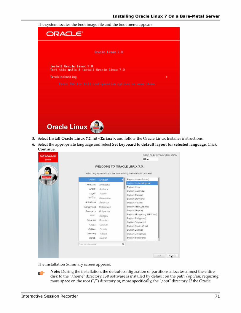
The system locates the boot image file and the boot menu appears.
5. Select Install Oracle Linux 7.2, hit <Enter>, and follow the Oracle Linux Installer instructions.
6. Select the appropriate language and select Set keyboard to default layout for selected language. ClickContinue.
The Installation Summary screen appears.
Note: During the installation, the default configuration of partitions allocates almost the entiredisk to the "/home" directory. ISR software is installed by default on the path /opt/isr, requiringmore space on the root ("/") directory or, more specifically, the "/opt" directory. If the Oracle
Installing Oracle Linux 7 On a Bare-Metal Server
Interactive Session Recorder 71

Linux 7 installer defaults are accepted, the ISR components can very easily run out of disk spaceand not function properly.
Installing Oracle Linux 7 On a Bare-Metal Server
72 Interactive Session Recorder

DConfiguring Automatic Start of the VMs
When all CIS components are installed, you must configure the virtual machines to start automatically.
Use the following procedure to configure the virtual machines to start automatically.
To configure the VMs to start automatically:
1. Open the vSphere Client application to the Home page.2. Click on the Configuration tab.
3. In the left column, under the Software category, click on Virtual Machine Startup/Shutdown. Thefollowing screen displays.
Interactive Session Recorder 73

4. In the upper right corner of the window, click Properties. The following window displays:
5. In System Settings section, enable the Allow virtual machines to start and stop automatically with thesystem by placing a check mark in the box.
6. In the Startup Order section, select the Index entry and then click <Move Up> to include the indexvirtual machine in the Automatic Startup group.
Note: When moving the entry up in the window, continue to click <Move Up> until the entry isin the appropriate category.
7. Select the Dashboard entry and then click <Move Up> to place the Dashboard VM just below the Indexentry in the Automatic Startup group.
8. Click OK. The window should displays as follows.
Configuring Automatic Start of the VMs
74 Interactive Session Recorder

You must continue the ISR installation process by installing the Record and Store Server (RSS). For RSSinstallation procedures, see Installing the RSS Software.
Configuring Automatic Start of the VMs
Interactive Session Recorder 75


EConfiguring the Timezone on an ISR
The timezone of each ISR has a default setting of America/New_York, also known as the Eastern TimeZone. To change the timezone on the ISR, the administrator must set all hosts to the timezone of choice andthe RSS hosts must be set to the same timezone as all ISRs (for RSS timezone configuration see the sectionConfiguring the Timezone in Chapter 4, Installing the RSS Software).
Note: It is important that your ISR component hosts are assigned the same timezone, except theIndex host, which must be set to UTC.
To configure the timezone of an ISR:
1. Connect to the ISR with an SSH client.2. Execute the rm -f /etc/localtime command to remove the previous timezone setting.3. Execute the following command to link the updated timezone.
ln -s /usr/share/zoneinfo/<region>/<timezone> /etc/localtimeNote: When you enter the /usr/share/zoneinfo/<region> and /usr/share/zoneinfo/<region>/<timezone> commands the CLI provides options for both the <region> and <timezone> arguments.
Interactive Session Recorder 77


FMounting a Second RSS Drive for Recordings
To mount a second new drive on the RSS for recording storage:
1. Using an SSH application (like Putty), SSH to the RSS server as root using the default password sips.2. Press Enter at both the "username" and "password" prompts.
The "Access granted since there are no configured users" prompt displays followed by the ISR> prompt.3. Format and mount the drive from the ISR> prompt (OS-E shell):
ISR> format data1 ext4These changes take affect upon restart.
4. Restart the RSS for the changes to take effect.
ISR> restart warmAre you sure (y or n)? yISR is restartingISR>
Mounting an Existing Pre-Formatted Second RSS DriveTo mount a second existing drive on the RSS for recording storage:
1. Using an SSH application (like Putty), SSH to the RSS server as root using the default password sips.2. Press Enter at both the "username" and "password" prompts.
The "Access granted since there are no configured users" prompt displays followed by the ISR> prompt.3. Format and mount the drive from the ISR> prompt (OS-E shell):
ISR> add-device data1 ext4These changes take affect upon restart.
4. Restart the RSS for the changes to take effect.
ISR> restart warmAre you sure (y or n)? yISR is restartingISR>
Interactive Session Recorder 79

Editing the vmgConfig.xml FileAfter completing the procedures in Mounting a Second RSS Drive for Recordings, you can make the newdrive the primary location for which the RSS writes recordings. To do this, you must edit thevmgConfig.xml file. Use the following procedure to edit the vmgConfig.xml file.
Note: For vmgConfig.xml parameter descriptions, see Appendix F, vmgConfig.xml Parameters.
To edit the vmgConfig.xml file:
1. Edit the /opt/isr/rss/vmgConfig.xml file.The initial location for all recordings is Line 6 of the XML file.
<Location>/opt/isr/Recordings</Location>2. Edit Line 6 to read <Location>/<Directory Name></Location>, replacing Directory Name with the
mount point created in the process step.For example,
<hostname> # <Location>/ArchivedRecordings</Location>3. Save the changes to the file.4. Enter systemctl restart recorderd for the RSS to use this new configuration.5. Confirm the /opt/isr/logs/recorder/recorder.log file has the new configuration written
towards the bottom of the file.
10/04/2011 06:01:23[NOTICE] mixMaster: Recordings Directory = /ArchivedRecordings
Mounting a Second RSS Drive for Recordings
80 Interactive Session Recorder
GCIS Troubleshooting
This Appendix provides FAQs and additional information regarding the CIS components for yourreference.
Log Collection ScriptsEach ISR component deployment contains a log collection script. To collect logs for a service request, runthe 'collectLogs.sh' script and attach the resulting TGZ file to the request.
Note: By default, the TGZ file can be found in the directory from where the script was executed.
vSphere HypervisorQ. How do I manage the virtual machine (VM) host?
A. You use the VMware vSphere client to monitor and configure the VM host. To install the vSphere client,see Chapter 3, Installing the CIS Software.
Q. What operating system do the virtual machines use?
A. All VMs use the Oracle Linux Server release 7.2.
Q. How do I monitor and manage the virtual machines?
A. You use the VMware vSphere client to monitor and configure the VMs. To install the vSphere client, seeChapter 3, Installing the CIS Software.
Q. What user and password is used to login on the guest OS?
A. All VMs have a "gansett" user with password "n3wf0und".
Q. What is the root password on the guest OS?
A. The root password for the guest OS is "64^5377".
A. Do I need to configure the database URL for the dashboards?
A. No. There is a local VM network (named VM Local) that includes the database VM (named "index")with IP address 192.168.1.50, and Dashboard VM (named "dashboard") on 192.168.1.25. These settings andthe "VM Local" virtual network remain static.
A. How do I download files from a virtual host?
Interactive Session Recorder 81

A. SSH file transfers with an SFTP client such as Filezilla using the root user and password gains access toany file on the system.
Index Virtual MachineQ. What version of MySQL Server is installed with the CIS?
A. The MySQL Server version is 14.14 Distrib 5.7.11, for Linux (x86_64).
Q. How do I connect directly to the CIS database in MySQL Server?
A. If the index VM was configured with a static IP on the VM Network, you can connect to the 'ipcr_db'database from a MySQL client with user 'Isr_admin' along with the password (for example, mysql -uisr_admin -p ipcr_db -h <Index_host_ip>.
Q. How do I view the logs in MySQL Server?
A. MySQL Server's log file can be found in the directory /var/lib/mysql.log. The main log file is named<host_name>.err. The error log can be found in the directory /var/lib/mysql/index.err.
If configured to do so, slow query logs can be found in the directory /var/lib/mysql/index-slow.log.
Note: All ISR-related errors are found in the respective component logs.
Q. How do I log slow queries in MySQL Server?
A. To start logging slow queries without restarting mysql server, execute the following:
1. At MySQL command prompt, enter set global slow_query_log=1.2. Enter set global long_query_time=1 (or whatever you want for query seconds).3. To verify the settings for these commands, use the following show variables: %slow% %length% By
default, the slow query logs are stored in the directory /var/lib/mysql/index-slow.log.
Q. How do I find the data files in MySQL Server?
A. Data files for the 'ipcr_db' database are found in the directory /var/lib/mysql/ipcr_db/.
Dashboard Virtual MachineQ. How do I log in to the ISR Dashboard?
A. Perform the following:
1. Open your Internet Web browser.2. Enter the IP address of the ISR. For example:
http://172.54.66.7The Login page displays.
3. Enter your email and password, respectively, in the Email and Password fields.
Note: When logging into the ISR Dashboard for the first time, you are required to enter newemail and password credentials, and then again every 90 days.
Q. How do I find the version of the ISR Dashboard?
A. The ISR Dashboard version number is shown on the bottom border of all pages in the graphical userinterface (GUI).
Q. How do I troubleshoot problems with the web interface on the Dashboard VM?
A. A common error during Dashboard deployment leaves the Dashboard unable to connect to theIndex VM database. If browsing to the Dashboard IP results in the display of a "500 Internal Server
CIS Troubleshooting
82 Interactive Session Recorder
Error" message (for example, in Chrome HTTP Error 500 (Internal Server Error): An unexpectedcondition was encountered while the server was attempting to fulfill the request.), the error should bedescribed in the Dashboard application log.
To access the application log:4. Access the Dashboard VM shell.5. Enter less /var/www/dashboard/current/log/production.log.6. Enter G to scroll to the bottom of the log.7. Scroll up the file looking for the following lines:
Status: 500 Internal Server ErrorCan’t connect to MySQL server on ‘169.254.1.50’ (113)
8. Enter q to exit.9. Enter ping 169.254.1.50.10. If the following appears:
PING 169.254.1.50 (169.254.1.50) 56(84) bytes of dataFrom 169.254.1.50 icmp_seq=2 Destination Host Unreachable.<Ctrl> C to discontinue the ping and check the network service status and connections on the Indexhost’s eth1 interface.
CIS Troubleshooting
Interactive Session Recorder 83


HvmgConfig.xml Parameters
This Appendix provides the parameters, the supported values, and the description of each parameter inthe vmgConfig.xml file. Refer to this appendix as required when editing the vmgConfig.xml file.
XML Parameters SupportedValues
Description
<NumberOfChannels>500</NumberOfChannels>
1 - 500 The number of sessions that should bestarted on this device. This parameter isrestricted by the license file.
<Recording>
<FullCallRecording>disabled</FullCallRecording>
<Location>/opt/isr/Recordings</Location>
enabled,disabled
accessibledirectory
enabled = ISR will not use recording rules,index recordings. It will record all trafficreceived and put files named<FileNameFormat> in <Location>.
disabled = ISR uses other sources toascertain how sessions should be recorded.This Is the standard behavior.
The location where recordings made on thisRSS will be written. This is normally the RSSitself.
<AlternativeLocation>/opt/isr/ArchivedRecordings </AlternativeLocation>
accessibledirectory
An alternate location where recordings willbe written. If <Location> is changed to aremote storage device,<AlternativeLocation> would allow you tospecify a fallback location in the event<Location> is not accessible. When<Location> is on the RSS,<AlternativeLocation> is not needed.
<ThirdLocation/> accessibledirectory
A third alternate location where recordingsare written. If <Location> is changed to aremote storage device, <ThirdLocation>would allow you to specify a fallback
Interactive Session Recorder 85

XML Parameters SupportedValues
Description
location in the event <Location> and<AlternativeLocation> are not accessible.When <Location> is on the RSS,<ThirdLocation> is not needed.
<FileNameFormat>%DNIS%-%CALLID%.wav</FileNameFormat>
text Any combination of letters and numbers, -(dash) and _ (underscore) along with systemvariables %DNIS%, %ANI%, %CALLID%,%DATE% that will be used as the defaultnaming convention for files.
<Format> true, false By default, with no parameter, this isdisabled. Set to true,<SeparateFilePerChannel>true</SeparateFilePerChannel>, if you want yourstereo recording to be in 2 separate files,caller in one file, called party in the other.Used in broadcast implementations.
Note: with this enabled , calls cannot be played back through theAcme provided dashboards.
<RIFFHeader>enabled</RIFFHeader>
<Encoding>linear</Encoding>
<BitRate>8</BitRate>
<NumberOfChannels>1</NumberOfChannels>
<SeparateFilePerChannel/>
</Format>
<BeepOnRecord>
<BeepFile>beep.wav</BeepFile>
<BeepIntervalSeconds>10</BeepIntervalSeconds>
<BeepOnRecordState>disabled</BeepOnRecordState>
<BeepDirection>ToCaller</BeepDirection>
</BeepOnRecord>
</Recording>
enabled,disabled
linear, ulaw,alaw, adpcm
8,16
1, 2
true, false
name of an 8bit8KHz ulaw file
numbers
enabled,disabled
ToCaller,ToCalledParty,ToBoth
Insert RIFF Header on WAV recordings
1 = mono
2 = stereo
By default, with no parameter, this isdisabled. Set to true,
<SeparateFilePerChannel>true</SeparateFilePerChannel>, if you want yourstereo recording to be in 2 separate files,caller in one file, called party in the other.Used in broadcast implementations.IMPORTANT -- with this enabled , calls cannot be played back through the Acmeprovided dashboards.
File that should be played when beep tone isenabled. This file needs to be placed in the<LocalRepository> directory specified in theCache section of this file.
Time, in seconds, between each beep, whenenabled in the dashboard.
This flag is obsolete. Beep enabled/disabledin AdminDashboard on route by route,account by account basis.
Specify who should hear the intermittentbeep tone.
<Sip> valid SIP URI Port RSS is listening for SIP Traffic.
vmgConfig.xml Parameters
86 Interactive Session Recorder

XML Parameters SupportedValues
Description
<SipPort>5060</SipPort>
<FromFormat>%ANI%@%IP%:%PORT%;channel=%CHANNEL%; call-id=%CALLID%</FromFormat>
<ToFormat>%DNIS%@%IP%:%PORT%</ToFormat>
<RejectionSubstitutionCode>-1</RejectionSubstitutionCode>
<RegistrarAddress/>
<RegistrarUserName/>
<RegistrarExpires>0</RegistrarExpires>
<AuthenticationUserId/>
<AuthenticationPassword/>
<AuthenticationRealm/>
<InviteTimeout>75</InviteTimeout>
<TransferInviteTimeout>75</TransferInviteTimeout>
<SipProxyAddress/>
<ForwardHoldRequest>disabled</ForwardHoldRequest>
<Supported>
<Headers/>
<ComfortNoise/>
</Supported>
<AuthorizedIncomingGateways>
<Host/>
</AuthorizedIncomingGateways>
</Sip>
valid SIP URI
Any valid SIPresponse
IP/FQDN ofRegistrar
text
numeric
text
text
text
1 - 180
1 - 180
enabled,disabled
SIP Header
Format of FROM header to be used onINVITES FROM the RSS back to theOutbound Session Agent. channel and callidare useful for API implemetnations. Theyshould not be removed.
Format of TO header to be used on INVITESFROM the RSS back to the OutboundSession Agent.
Error Message to be sent back in the eventthe RSS is unable to accept a call. Overridesall Error responses. -1 indicates no override,use standard rejection message.
IF RSS must register as endpoint, whataddress should it register with.
Registrar User Name
Registar Expiration. Default is no expiration.
User ID for Challenge Authentication
Password for Challenge Authentication
Realm for Challenge Authentication
Timer, in seconds, for how long RSS willwait for 18x message on an INVITE
Timer, in seconds, for how long RSS willwait for 18x message on an REFER
Header name that should be taken fromincoming INVITE and added to outgoingINVITE
With no values, RSS accepts all incomingINVITEs and evaluates for recording. Torestrict devices, enumerate.
<XmlRpc>
<ServerPort>8888</ServerPort>
<AllowedHosts>
<Host/>
</AllowedHosts>
<QueryAgent>
<Enabled>true</Enabled>
<Host>localhost</Host>
true, false
IP/FQDN
port
enabled,disabled
enabled,disabled
time, seconds
Port where XML RPC server is listening.This should not be changed.
Hosts that should be allowed to issue APIcommands
If true, RSS will connect to CIS to getrecording rules. If false, RSS expects thateither <FullCallRecording> is enabled OR<SkipVoiceBrowserMode> is disabled. DONOT EDIT UNLESS DIRECTED.
vmgConfig.xml Parameters
Interactive Session Recorder 87

XML Parameters SupportedValues
Description
<Port>8887</Port>
<SkipVoiceBrowserMode>enabled</SkipVoiceBrowserMode>
<LocalRouteMapCache>enabled</LocalRouteMapCache>
<LocalRouteMapCacheUpdateInterval>300</LocalRouteMapCacheUpdateInterval>
</QueryAgent>
</XmlRpc>
IP Address of XMLRPC Query Agent. Isinstalled on each RSS host. DO NOT EDITUNLESS DIRECTED.
Port for XMLRPC Query Agent. DO NOTEDIT UNLESS DIRECTED.
If disabled, RSS will issue INVITE toaddress specified in <IVRGateway> forrecording rules. This is the RSS 1.4implementation and is here for backwardscompatibility. DO NOT EDIT UNLESSDIRECTED.
If disabled, RSS will need to communiatewith CIS on every call, which could impactperformance. DO NOT EDIT UNLESSDIRECTED.
Interval, in seconds, that RSS shouldattempt to refresh the route map cache andread in changes in the CIS. 5 minutes is thedefault. This is the maximum amount oftime that will elapse before a change in theAdminDashboard will be applied toincoming sessions.
<TransferDropOutMode>disabled</TransferDropOutMode>
<Rtp>
<ListenPortStart>22000</ListenPortStart>
<SendPortStart>32000</SendPortStart>
<MinimumPacketSize>1</MinimumPacketSize>
<MaximumPacketSize>160</MaximumPacketSize>
<RtpInCheckPacketSource/>
<TransferMuteAudio/>
<MissingMediaDetection>
<SessionEstablishment>
<WarnAfterSeconds>10</WarnAfterSeconds>
<TerminateSessionAfterSeconds>300</TerminateSessionAfterSeconds>
</SessionEstablishment
</SessionInProgress
disabled,enabled
1 - 66535
1 - 66535
Should the RSS drop out of the call when arequest to transfer is received? If disabled,RSS will continue to record. If enabled, RSSwill remove itself from the call path ontransfer request.
vmgConfig.xml Parameters
88 Interactive Session Recorder
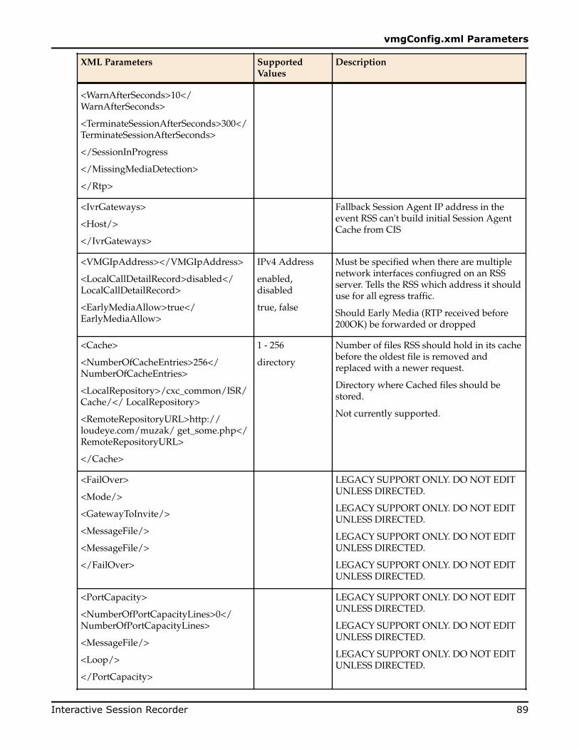
XML Parameters SupportedValues
Description
<WarnAfterSeconds>10</WarnAfterSeconds>
<TerminateSessionAfterSeconds>300</TerminateSessionAfterSeconds>
</SessionInProgress
</MissingMediaDetection>
</Rtp>
<IvrGateways>
<Host/>
</IvrGateways>
Fallback Session Agent IP address in theevent RSS can't build initial Session AgentCache from CIS
<VMGIpAddress></VMGIpAddress>
<LocalCallDetailRecord>disabled</LocalCallDetailRecord>
<EarlyMediaAllow>true</EarlyMediaAllow>
IPv4 Address
enabled,disabled
true, false
Must be specified when there are multiplenetwork interfaces confiugred on an RSSserver. Tells the RSS which address it shoulduse for all egress traffic.
Should Early Media (RTP received before200OK) be forwarded or dropped
<Cache>
<NumberOfCacheEntries>256</NumberOfCacheEntries>
<LocalRepository>/cxc_common/ISR/Cache/</ LocalRepository>
<RemoteRepositoryURL>http://loudeye.com/muzak/ get_some.php</RemoteRepositoryURL>
</Cache>
1 - 256
directory
Number of files RSS should hold in its cachebefore the oldest file is removed andreplaced with a newer request.
Directory where Cached files should bestored.
Not currently supported.
<FailOver>
<Mode/>
<GatewayToInvite/>
<MessageFile/>
<MessageFile/>
</FailOver>
LEGACY SUPPORT ONLY. DO NOT EDITUNLESS DIRECTED.
LEGACY SUPPORT ONLY. DO NOT EDITUNLESS DIRECTED.
LEGACY SUPPORT ONLY. DO NOT EDITUNLESS DIRECTED.
LEGACY SUPPORT ONLY. DO NOT EDITUNLESS DIRECTED.
<PortCapacity>
<NumberOfPortCapacityLines>0</NumberOfPortCapacityLines>
<MessageFile/>
<Loop/>
</PortCapacity>
LEGACY SUPPORT ONLY. DO NOT EDITUNLESS DIRECTED.
LEGACY SUPPORT ONLY. DO NOT EDITUNLESS DIRECTED.
LEGACY SUPPORT ONLY. DO NOT EDITUNLESS DIRECTED.
vmgConfig.xml Parameters
Interactive Session Recorder 89

XML Parameters SupportedValues
Description
<Sip>
<IsrUcidHeaderField> X-ISR-UCID </IsrUcidHeaderField>
</Sip>
Configures the X-ISR-UCID header field inSIP INVITE messages.
<Siprec>
<SiprecEnabled/>
</Siprec>
true, false Enables or disables SIPREC support. Thedefault is false.
<WebService>
<ServerPort/>
<SSLCertificateKeyFile/>
</WebService>
<ServerPort/> -port # (default9998)<SSLCertificateKeyFile/> -certificate filelocation(default /opt/isr/cert.pem)
These parameters enable the RSS RESTWebservice to listen on a specific port andenable HTTPS wiht the specified certificatefile name and path.
<WebService>
<serverPort>9998</ServerPort>
<SSLCertificateKeyFile>/opt/isr/cert.pem</SSLCertificateKeyFile>
</WebService>
vmgConfig.xml Parameters
90 Interactive Session Recorder

ISelective Call Recording/SIPREC
The SIPREC protocol is the protocol used to interact between a Session Recording Client (SRC) (the roleperformed by ESD) and a Session Recording Server (SRS) (a 3rd party call recorder or the ISR’s Record andStore Server (RSS)). It controls the recording of media transmitted in the context of a communicationssession (CS) between multiple user agents.
SIPREC provides a selective-based call recording solution that increases media and signaling performanceon 3rd party call recording servers, more robust failovers, and the ability to selectively record.
Note: SIPREC isolates the 3rd party recorders from the communication session. The 3rd partyrecorders can determine whether or not recording is desired.
Note: The SRC starts a recording session for every call within a configured realm. All call filtering,if desired, must be accomplished by the SRS. The SRS performs the filtering and selection of whichsessions it should record.
License/Hardware RequirementsSIPREC requires the purchase of a Session Recording license. Contact your Acme Packet Representative formore information.
SIPREC is currently supported on all Enterprise Acme Packet platforms.
How it WorksThe SIPREC feature supports active recording, where the ESD acting as the SRC, purposefully streamsmedia to the ISR’s RSS (or 3rd party call recorder) acting as the SRS. The SRC and SRS act as SIP UserAgents (UAs). The SRC provides additional information to the SRS to describe the communicationsessions, participants and media streams for the recording session to facilitate archival and retrieval of therecorded information.
The ESD acting as the SRC, is the source for the recorded media. The ESD consumes configurationinformation describing the ecosystem within which it operates. The interface, realm and session agentconfiguration objects specify the SIPREC configuration. A SIP UA can elect to allow or disallow anynetwork element from recording its media.
During the establishment of a SIP Session, the ESD determines if SIPREC is configured for recording thecall. If so, it then duplicates the media prior to initiating the session with the SRS. (Media replication is setup prior to the recording session). The SRS may choose to record, not record, or cancel the recording
Interactive Session Recorder 91

session, and then communicates via SIP signaling to the ESD. If the call is not to be recorded, the SRSsignals termination of the recording session.
The ESD maintains SIPREC metadata information associated with recording sessions. The recordingsession metadata describes the current state of the recording session and its communication session(s). It isupdated when a change of state in the communication session(s) is observed by the ESD. The SRS isresponsible for maintaining call history, etc. The ESD creates and logs call detail records (CDRs) in thecurrent manner, the 3rd party SRS vendor may collate this information if desired. (For more informationabout the contents of metadata, see Metadata Contents).
The following illustration shows two endpoints, User Agent A (UA-A) and User Agent B (UA-B). Theirsession is being recorded by an SRC (the ESD) and an SRS.
Configuring SIPRECThis section defines the information required to configure SIPREC on the ESD. It also provides a sampleprocedure for configuring SIPREC using the Acme Packet Command Line Interface (ACLI).
Session Recording Server (SRS)The ISR's RSS acts as the SRS in the network. A session-recording-server attribute under the session-router object in the ESD ACLI allows you to enable/disable the SRS. This object is the session recordingserver that receives replicated media and records signaling. Additional parameters for SRS are configuredunder the session-agent, realm-config, and sip-interface objects. The rules of precedence for which theESD uses these parameters are: session-agent takes precedence over the realm-config, and realm-configtakes precedence over sip-interface.
Each SRS is associated with a realm-config. The realm specifies the source interface from which replicatedtraffic originates. The destination is an IP Port parameter (IP address or hostname with an optional port)that defines the SIP address (request URI) of the actual SRS.
For an additional level of security, Acme Packet recommends the SRS be configured in its own realm so asto apply a set of access control lists (ACLs) and security for the replicated communication.
The ESD supports large UDP packets, and ISR currently only supports SRS realms provisioned with a UDPport.
Selective Call Recording/SIPREC
92 Interactive Session Recorder
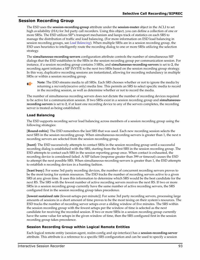
Session Recording GroupThe ESD uses the session-recording-group attribute under the session-router object in the ACLI to sethigh availability (HA) for 3rd party call recorders. Using this object, you can define a collection of one ormore SRSs. The ESD utilizes SIP’s transport mechanism and keeps track of statistics on each SRS tomanage the distribution of traffic and load balancing. (For more information on ESD load balancing insession recording groups, see Load Balancing). When multiple SRSs are in a session recording group, theESD uses heuristics to intelligently route the recording dialog to one or more SRSs utilizing the selectionstrategy.
The simultaneous-recording-servers configuration attribute controls the number of simultaneous SIPdialogs that the ESD establishes to the SRSs in the session recording group per communication session. Forinstance, if a session recording group contains 3 SRSs, and simultaneous-recording-servers is set to 2, therecording agent initiates a SIP INVITE to the next two SRSs based on the session recording group strategy.In this way, duplicative recording sessions are instantiated, allowing for recording redundancy in multipleSRSs or within a session recording group.
Note: The ESD streams media to all SRSs. Each SRS chooses whether or not to ignore the media byreturning a recvonly(receive only) media line. This permits an SRS to select specific media to recordin the recording session, as well as determine whether or not to record the media.
The number of simultaneous recording servers does not dictate the number of recording devices requiredto be active for a communication session. If two SRSs exist in a session recording group and simultaneous-recording-servers is set to 2, if at least one recording device to any of the servers completes, the recordingserver is treated as being established.
Load Balancing
The ESD supports recording server load balancing across members of a session recording group using thefollowing strategies:
[Round-robin]: The ESD remembers the last SRS that was used. Each new recording session selects thenext SRS in the session recording group. When simultaneous-recording-servers is greater than 1, the next nrecording servers are selected from the session recording group.
[hunt]: The ESD successively attempts to contact SRSs in the session recording group until a successfulrecording dialog is established with the SRS, starting from the first SRS in the session recording group. TheESD attempts to contact each SRS in the session reporting group once. When contact is exhausted, therecording device is considered failed. A SIP failure (response greater than 399 or timeout) causes the ESDto attempt the next possible SRS. When simultaneous-recording-servers is greater than 1, the ESD attemptsto establish n recording devices in a hunting fashion.
[least busy]: For some 3rd party recording devices, the number of concurrent recording servers proves tobe the most taxing for system resources. The ESD tracks the number of recording servers active to a givenSRS at any given time. It uses this information to determine which SRS would be the best candidate for thenext RS. The SRS with the fewest number of active recording servers receives the next RS. If two or moreSRSs in a session recording group currently have the same number of active recording servers, the SRSconfigured first in the session recording group takes precedence.
[lowest sustained rate (fewest-setups-per-minute)]: For some 3rd party recording servers, processing largeamounts of sessions in a short amount of time proves to be the most taxing on their system's resources. TheESD tracks the number of recording server setups over a sliding window of five minutes. The SRS withinthe session recording group with the fewest setups per the window of time is selected as the nextcandidate for receiving the recorded session. If two or more SRSs in a session recording group currentlyhave the same value for setups in the given window of time, then the SRS configured first in the sessionrecording group takes precedence.
Session Recording Group within Logical Remote Entities
Each logical remote entity (session-agent, realm-config and sip-interface) has a session-recording-serverattribute. This attribute is a reference to a specific SRS configuration and can be used to specify a session
Selective Call Recording/SIPREC
Interactive Session Recorder 93

recording group instead. If a session recording group is specified instead of an SRS, the session recordinggroup name must be prefixed with "SRG:" followed by the session recording group name. Thisdistinguishes between an SRS being referenced and a session recording group being referenced.
When the ESD is configured for legacy SRR features, it is possible to configure a call recording server onboth the ingress and egress realms. If configured, the ESD uses the egress call recording server to record.However, with SIPREC, this process works differently. With SIPREC, if an SRS or session recording groupis configured on both the ingress and egress logical remote entities, both the ingress and egress SRS/session recording groups are used. This means that the ESD records the media between participants twice(or more) - once for the ingress recorders and once for the egress recorders.
If both the ingress and egress SRS/session recording group are the same, the ESD makes an optimizationand only records the media once. Even if the ingress session recording group is the same exact set of SRSsas the egress session recording group (but with a different name), the ESD replicates media to bothdestinations. However, if the same set of SRSs has the exact same identifier, the ESD sends media to oneand not both SRSs.
Selective RecordingSIPREC defines a number of use cases for which the ESD can record communication sessions. These usecases include the use of selective based recording. A selective recording is one in which a uniquerecording server is created per communication session.
Note: The ESD does not support persistent recording.
For SRSs using selective recording, recording servers are unique per session recording group. For eachselective SRS in a session recording group, during the setup of a new communication session, the recordingmetadata is the same for each recording device. The SRC initiates a new SIP INVITE to the SRS carryingthe metadata for that new recording server. The recording agent terminates the SIP dialog at the time thatthe recording session ends.
The lifetime of a recording session extends beyond the lifetime of the recorded communication. The SRC( ESD) re-uses the recording session ID in the metadata instead of creating a new ID for each recording.
High Availability (HA) SupportAn ESD using SIPREC supports HA in the network. The ESD replicates all metadata states between theactive and standby ESDs. Any recording dialogs in progress do not survive the failover, but all calls inprogress are preserved. Additionally, the recording dialogs are replicated as well to the failed over ESD sothat in-dialog SIP requests continue to function.
Each recorded communication session replicated to a single SRS counts as two calls instead of one. TheESD creates two flows between the two participants and two additional flows to the SRS for each of theparent flows.
Single SRS
Assuming that each communication session (CS) is recorded to a single SRS with a single recordingsession, the total session capacity for recorded sessions is 4000.
SIPREC Configuration ProcedureThe following configuration example assumes the ESD has the session recording license enabled on theESD. Changes to the call session recording configuration for SIPREC are dynamic. Active calls in progressremain unaffected by the configuration changes. New calls, however, utilize the changes after a Save andActivate of the configuration.
The following attributes must be configured:
• session-recording-server
Selective Call Recording/SIPREC
94 Interactive Session Recorder

• session-recording-group (for RSS or 3rd party SRS high availability (HA) only) and at least one of thefollowing attributes:
• realm-config• session-agent• sip-interface
Session-recording-server Attribute
To configure the session-recording-server attribute:
1. In Superuser mode, type configure terminal and press Enter.
ACMEPACKET# configure terminal2. Type session-router and press Enter to access the session router-related objects.
ACMEPACKET(configure)# session-routerACMEPACKET(session-router)#
3. Type session-recording-server and press Enter to access the session recording server-related attributes.
ACMEPACKET(session-router)# session-recording-serverACMEPACKET(session-recording-server)#
4. name — Enter a unique name for the session recording server. This name can be referenced whenconfiguring realm-config, session-agent, and sip-interface. Valid values are alpha-numeric characters.Default is no value specified.
ACMEPACKET(session-recording-server)# name SRS15. (optional) description — Enter a description for the session recording server. Valid values are alpha-
numeric characters. Default is no value specified.
ACMEPACKET(session-recording-server)# description <recording server name>6. realm — Enter the realm for which the session recording server belongs. Valid values are alpha-numeric
characters. Default is no value specified.
ACMEPACKET(session-recording-server)# realm <realm name>Note: Acme Packet recommends that the session recording server be configured in its ownrealm.
7. recording-mode — Enter the recording mode for the session recording server. Valid values are:
• selective (default) - Unique recording server created per communication session• persistent - Not supported. If selected, this option behaves the same as the selective option.
ACMEPACKET(session-recording-server)# recording-mode selective8. destination — Enter the destination IP address with IP port (port specification is optional) that defines
the SIP address (request URI) of the session recording server. Enter values in the format 0.0.0.0:<portnumber>. Default is no value specified.
ACMEPACKET(session-recording-server)# destination 172.34.2.3:50609. protocol — Enter the protocol that the session recording server uses to accept incoming packets from
the session reporting client on the network. Default is UDP.
ACMEPACKET(session-recording-server)# protocol UDP10. Enter done to save the session recording configuration.
ACMEPACKET(session-recording-server)# done11. Enter exit to exit the session-recording-server configuration.
ACMEPACKET(session-recording-server)# exit12. Enter exit to exit the session-router configuration.
ACMEPACKET(session-router)# exit13. Enter exit to exit the configure mode.
Selective Call Recording/SIPREC
Interactive Session Recorder 95

ACMEPACKET(configure)# exit14. Enter save-config to save the session recording configuration.
ACMEPACKET# save-config15. Enter activate-config to activate the session recording configuration.
ACMEPACKET# activate-config
Session-recording-group Attribute (for HA only)
For environments that required high availability (HA) requirements, configure the session-recording-group attribute.
To configure the session-recording-group attribute and enable HA:
1. In Superuser mode, type configure terminal and press Enter.
ACMEPACKET# configure terminal2. Type session-router and press Enter to access the session router-related objects.
ACMEPACKET(configure)# session-routerACMEPACKET(session-router)#
3. Type session-recording-group and press Enter to access the session recording group-related attributes.
ACMEPACKET(session-router)# session-recording-groupACMEPACKET(session-recording-group)#
4. name — Enter a unique name for the session recording group that is a collection of one or more sessionrecording servers. This name can be referenced when configuring realm-config, session-agent, and sip-interface. Valid values are alpha-numeric characters. Default is no value specified.
ACMEPACKET(session-recording-group)# name <SRG Group Name>Note: The name of the session recording group must be prefixed with SRG.
5. (optional) description — Enter a description for the session recording group. Valid values are alpha-numeric characters. Default is no value specified.
ACMEPACKET(session-recording-group)# description <Recording Group Name>6. session-recording-servers — Enter the names of the session recording servers that belong to this
session recording group. Valid values are alpha-numeric characters. Default is no value specified.
ACMEPACKET(session-recording-group)# session-recording-servers SRS1,SRS2Note: You must enter multiple servers as values for the session-recording-servers attribute.
7. strategy — Enter the load balancing strategy that the session reporting client ( ESD) uses when sendingrecordings to the session reporting server. Valid values are:
• Round-robin (default) - The ESD remembers the last SRS that was used. Each new recording sessionselects the next SRS in the session recording group. When simultaneous-recording-servers is greaterthan 1, the next n recording servers are selected from the session recording group.
• hunt - The ESD successively attempts to contact SRSs in the session recording group until asuccessful recording dialog is established with the SRS, starting from the first SRS in the sessionrecording group. The ESD attempts to contact each SRS in the session reporting group once. Whencontact is exhausted, the recording device is considered failed. A SIP failure (response greater than399 or timeout) causes the ESD to attempt the next possible SRS. When simultaneous-recording-servers is greater than 1, the ESD attempts to establish n recording devices in a hunting fashion.
• least busy - For some 3rd party recording devices, the number of concurrent recording serversproves to be the most taxing for system resources. The ESD tracks the number of recording serversactive to a given SRS at any given time. It uses this information to determine which SRS would bethe best candidate for the next RS. The SRS with the fewest number of active recording serversreceives the next RS. If two or more SRSs in a session recording group currently have the same
Selective Call Recording/SIPREC
96 Interactive Session Recorder

number of active recording servers, the SRS configured first in the session recording group takesprecedence.
• lowest sustained rate (fewest-setups-per-minute) - For some 3rd party recording servers, processinglarge amounts of sessions in a short amount of time proves to be the most taxing on their system'sresources. The ESD tracks the number of recording server setups over a sliding window of fiveminutes. The SRS within the session recording group with the fewest setups per the window of timeis selected as the next candidate for receiving the recorded session. If two or more SRSs in a sessionrecording group currently have the same value for setups in the given window of time, then the SRSconfigured first in the session recording group takes precedence.
ACMEPACKET(session-recording-group)# strategy round-robin8. simultaneous-recording-servers — Enter the number of simultaneous SIP dialogs that the session
reporting client ( ESD) establishes to the session reporting servers in the session reporting group percommunication session. Valid values are 1 to 100. Default is 0.
ACMEPACKET(session-recording-group)# simultaneous-recording-servers 29. Enter done to save the session recording group configuration.
ACMEPACKET(session-recording-group)# done10. Enter exit to exit the session recording group configuration.
ACMEPACKET(session-recording-group)# exit11. Enter exit to exit the session-router configuration.
ACMEPACKET(session-router)# exit12. Enter exit to exit the configure mode.
ACMEPACKET(configure)# exit13. Enter save-config to save the session recording group configuration.
ACMEPACKET# save-config14. Enter activate-config to activate the session recording group configuration.
ACMEPACKET# activate-config
Realm-config Attribute
To configure the realm-config attribute and enable session recording:
1. In Superuser mode, type configure terminal and press Enter.
ACMEPACKET# configure terminal2. Type media-manager and press Enter to access the media manager-related objects.
ACMEPACKET(configure)# media-managerACMEPACKET(media-manager)#
3. Type realm-config and press Enter to access the realm-config-related attributes.
ACMEPACKET(media-manager)# realm-configACMEPACKET(realm-config)#
4. session-recording-server — Enter the name of the session-recording server or the session-recording-group in the realm associated with the session reporting client ( ESD). Valid values are alpha-numericcharacters. Default is no value specified.
ACMEPACKET(realm-config)# session-recording-server <srs-name>or
ACMEPACKET(realm-config)# session-recording-server SRG:<group-name>Note: The value for this attribute is the name you specified in Step 4 of the Session-recording-server Attribute or Step 4 of the Session-recording-grou Attribute. If specifying a session-recording-group, you must precede the group name with SRG:.
Selective Call Recording/SIPREC
Interactive Session Recorder 97

5. session-recording-required — Enter whether or not you want a call to be accepted by the ESD ifrecording is not available. Valid values are:
• Enabled - Restricts call sessions from being initiated when a recording server is not available.• Disabled (default)- Allows call sessions to initiate even if the recording server is not available.
ACMEPACKET(realm-config)# session-recording-required disabledNote: Acme Packet recommends that the session-recording-required parameter remaindisabled.
6. Enter done to save the realm configuration.
ACMEPACKET(realm-config)# done7. Enter exit to exit the realm configuration.
ACMEPACKET(realm-config)# exit8. Enter exit to exit the media manager configuration.
ACMEPACKET(media-manager)# exit9. Enter exit to exit the configure mode.
ACMEPACKET(configure)# exit10. Enter save-config to save the realm configuration.
ACMEPACKET# save-config11. Enter activate-config to activate the realm configuration.
ACMEPACKET# activate-config
Session-agent Attribute
To configure the session-agent attribute and enable session recording:
1. In Superuser mode, type configure terminal and press Enter.
ACMEPACKET# configure terminal2. Type session-router and press Enter to access the session router-related objects.
ACMEPACKET(configure)# session-routerACMEPACKET(session-router)#
3. Type session-agent and press Enter to access the session agent-related attributes.
ACMEPACKET(session-router)# session-agentACMEPACKET(session-agent)#
4. session-recording-server — Enter the name of the session-recording server or the session-recording-group to apply to the session recording client ( ESD). Valid values are alpha-numeric characters. Defaultis no value specified.
ACMEPACKET(session-agent)# session-recording-server <srs-name>or
ACMEPACKET(session-agent)# session-recording-server SRG:<group-name>Note: The value for this attribute is the name you specified in Step 4 of the Session-recording-server Attribute or Ste 4 of the Session-recording-group Attribute (for HA only). If specifying asession-recording-group, you must precede the group name with SRG:.
5. session-recording-required — Enter whether or not you want a call to be accepted by the ESD ifrecording is not available. Valid values are:
• Enabled - Restricts call sessions from being initiated when a recording server is not available.• Disabled (default)- Allows call sessions to initiate even if the recording server is not available.
ACMEPACKET(session-agent)# session-recording-required disabled
Selective Call Recording/SIPREC
98 Interactive Session Recorder

Note: Acme Packet recommends that the session-recording-required parameter remaindisabled.
6. Enter exit to exit the session agent configuration.
ACMEPACKET(session-agent)# exit7. Enter exit to exit the session router configuration.
ACMEPACKET(session-router)# exit8. Enter exit to exit the configure mode.
ACMEPACKET(configure)# exit9. Enter save-config to save the session agent configuration.
ACMEPACKET# save-config10. Enter activate-config to activate the session agent configuration.
ACMEPACKET# activate-config
Sip-interface Attribute
To configure the sip-interface attribute and enable session recording:
1. In Superuser mode, type configure terminal and press Enter.
ACMEPACKET# configure terminal2. Type session-router and press Enter to access the session router-related objects.
ACMEPACKET(configure)# session-routerACMEPACKET(session-router)#
3. Type sip-interface and press Enter to access the SIP interface-related attributes.
ACMEPACKET(session-router)# sip-interfaceACMEPACKET(sip-interface)#
4. session-recording-server — Enter the name of the session-recording server or the session-recording-group to apply to the SIP interface on the session recording client (ESD). Valid values are alpha-numericcharacters. Default is no value specified.
ACMEPACKET(sip-interface)# se ss on-recording-server SRG:<session recording server name or session-recording group name>
Note: The value for this attribute is the name you specified in Step 4 of the Session-recording-server Attribute or Step 4 of the Session-recording-grou Attribute (for HA only).
5. session-recording-required — Enter whether or not you want a call to be accepted by the ESD ifrecording is not available. Valid values are:
• Enabled - Restricts call sessions from being initiated when a recording server is not available.• Disabled (default)- Allows call sessions to initiate even if the recording server is not available.
ACMEPACKET(sip-interface)# session-recording-required disabledNote: Acme Packet recommends that the session-recording-required parameter remaindisabled.
6. Enter exit to exit the SIP interface configuration.
ACMEPACKET(sip-interface)# exit7. Enter exit to exit the session router configuration.
ACMEPACKET(session-router)# exit8. Enter exit to exit the configure mode.
ACMEPACKET(configure)# exit9. Enter save-config to save the SIP interface configuration.
ACMEPACKET# save-config
Selective Call Recording/SIPREC
Interactive Session Recorder 99

10. Enter activate-config to activate the SIP interface configuration.
ACMEPACKET# activate-config
Metadata ContentsThe recording metadata contains a set of related elements which define the recording session. A recordingsession may contain zero or more communication sessions and/or communication session groups. Acommunication session represents a call instance; a communication session group represents a relatedgroup of communication sessions. A recording session is composed of a sequence of complex elementtypes. Not all element types are required to describe a recording session initiated from the ESD. Therecording session XML schema defines the following element types:
• dataMode - partial or complete metadata description (required)• group - a collection of related communication sessions• session - a single communication session of two or more participants (required)• participant - a SIP endpoint representation (required)• stream - a media stream• extensiondata - application specific data outside of the SIPREC scope.
The recording agent generates dataMode, session, participant, and stream elements. Extension data isattached to other elements within the metadata through the use of the parent attribute. The recordingmetadata is defined as a sequence of element types; therefore all associations between elements arerepresented as references to element identifiers.
The state of the metadata within a recording session reflects the state of the communication session(s)which is being recorded. SIPREC implements stop-times and reason codes when communication sessionsend within a recording session. Once a communication session, participant, or media stream has beenmarked as 'stopped' and accepted by the SRS, the metadata item is removed from the current metadatastate. In addition, media lines within the SDP or the recording session may be re-used/re-labeled for reuseif new communication sessions and media streams are created within the recording session.
The XML schema for the recording metadata is defined in the IETF draft RFC draft-ram-siprec-metadata-format-02 [7].
The ACLI command to show recorded metadata is show rec. For more information on this command seethe section, Show rec.
Show Commands for Recording SessionsThe ESD allows you to utilize the following show commands via the ACLI to display statisticalinformation about recording sessions:
• show rec• show rec redundancy
Show rec
The show rec command displays the count of all metadata objects in sessions managed by the recordingagent. These statistics include metadata monitored over an active period of time and over a lifetime period(where lifetime totals reflect from the last reboot of the ESD to the present time). The following exampleshows the use of this command.
1. Log into the ESD as a User or Superuser.
ACMEPACKET> enableACMEPACKET(enable)#
2. Type show rec and press Enter to display the recording metadata statistics. The following output is anexample of the show rec command.
ACMEPACKET(enable)# show rec13:49:44-81645
Selective Call Recording/SIPREC
100 Interactive Session Recorder

Recording Agent Status -- Period -- -------- Lifetime -------- Active High Total Total PerMax HighRec Sessions 0 1 1 1 1 1Comm Groups 0 0 0 0 0 0Comm Sessions 0 1 1 1 1 1Media Streams 0 2 2 2 2 2Participants 0 2 2 2 2 2The following table describes the metadata objects in the show rec command output.
Object Description
Rec Sessions Number of recording sessions during an active period of time and over alifetime period.
Comm Groups Number of active communication session recording groups during an activeperiod of time and over a lifetime period.
Comm Sessions Number of active communication sessions during an active period of time andover a lifetime period.
Media Streams Number of active media streams during an active period of time and over alifetime period.
Participants Total number of participants in session recordings during an active period oftime and over a lifetime period.
Show rec redundancy
The show rec redundancy command displays information for session recording server statistics when theESD is configured for HA. These statistics include metadata monitored over an active period of time andover a lifetime period (where lifetime totals reflect from the last reboot of the ESD to the present time) onboth the primary and redundant ESD. The following example shows the use of this command.
1. Log into the ESD as a User or Superuser.
ACMEPACKET> enableACMEPACKET(enable)#
2. Type show rec redundancy and press Enter to display the session recording server statistics for ESDs inHA mode. The following output is an example of the show rec redundancy command.
ACMEPACKET(enable)# show rec redundancy13:49:44-81645Recording Agent Status -- Period -- -------- Lifetime -------- Active High Total Total PerMax HighRec Sessions 0 1 1 1 1 1Comm Groups 0 0 0 0 0 0Comm Sessions 0 1 1 1 1 1Media Streams 0 2 2 2 2 2Participants 0 2 2 2 2 2The following table describes the session recording server statistics in the show rec redundancycommand output.
Object Description
Rec Sessions Number of recording sessions during an active period of time and over alifetime period.
Comm Groups Number of active communication session recording groups during an activeperiod of time and over a lifetime period.
Comm Sessions Number of active communication sessions during an active period of time andover a lifetime period.
Selective Call Recording/SIPREC
Interactive Session Recorder 101

Object Description
Media Streams Number of active media streams during an active period of time and over alifetime period.
Participants Total number of participants in session recordings during an active period oftime and over a lifetime period.
Codec NegotiationIn a SIPREC environment, it is assumed that the recording ecosystem provides transcoding media serversfor which media calls can be redirected to, relieving the issue of codec matching from the recordingservers. However, if transcoding media servers are not provided, the responsibility for transcoding falls onthe recording server or the recording client in a SIPREC environment. The ESD/SRC is required to imposesome policy decisions on the codec negotiation between the three, or more, end-points. Specifically, thecodec negotiation between the two participants and the recording server is subject to additional policyactions.
The SDP answer from the SRS may not agree with the media flows established in the communicationsession between UA-A and UA-B. If UA-A and UA-B agree to use G729, yet the SRS's answer indicates nosupport for G729, the SRS is then unable to interpret the media streams. The SDP offer forwarded to thecalled party (in this case UA-B) limits the codec choices to those supported by the SRS.
Note: The recording agent forwards the original codec offer to the SRS prior to sending the invite tothe UA-B. The SRS responds with the SDP answer, indicating the codec list most desirable to theSRS. The codec list in the answer is then forwarded to UA-B. This allows three parties in aconference call to participate in the negotiation of the codecs among the supported formats only.
Codec Negotiation Support For All Packet TimesThe ISR supports codec negotiation for all additional packet times (ptimes) within codecs supported by theRSS, specifically including but not limited to 30ms, G.711, and ulaw/alaw.
SIPREC Call FlowsThis section provides examples of call flow scenarios that can occur in a SIPREC environment. SIPrecording call flow examples include:
For Selective Recording:
• Normal Call (recording required)• Normal Call (recording not required)• Early Media Call (recording not required)• REFER Pass-Through Call (REFER handled by User Agent)• REFER Call (REFER handled by ESD)• SRS Indicates Busy in Call (recording not required)
Note: REFER is a SIP method indicating that the recipient (identified by the Request-URI)should contact a third party using the contact information provided in the request.
Selective Recording
Normal Call (recording required)
The following illustration shows a normal call using selective recording with recording required. For SDPand Metadata information in Notes 1 and 2 , see Sample SDP and Metadata.
Selective Call Recording/SIPREC
102 Interactive Session Recorder

I
Call Flow Description
q UA-A sends INVITE to ESD. a RTP stream initiated between ESD and UA-B.
w ESD forwards INVITE with SDP and metadata toSRS.
s RTP stream initiated between ESD and SRS.
e SRS responds with OK to ESD. d UA-A sends BYE to ESD.
r ESD sends INVITE to UA-B. f ESD responds with OK to UA-A.
t UA-B responds with OK to ESD. g ESD sends BYE to ESD.
y ESD sends re-INVITE with SDP and metadatachanges to SRS.
h ESD responds with OK to UA-A.
u SRS responds with OK to ESD. j ESD sends BYE to UA-B.
i ESD forwards OK response to UA-A. k UA-B responds with OK to ESD.
o RTP stream initiated between UA-A and ESD. l ESD sends BYE to SRS.
; SRS responds with OK to ESD.
Sample SDP and Metadata
The following sample SDP and Metadata pertain to Notes 1 and 2 in the previous Call Flow diagram.
--[Note 1]------------------------------Content-Type: application/sdp
Selective Call Recording/SIPREC
Interactive Session Recorder 103

v=0o=- 171 213 IN IP4 10.0.0.2s=-c=IN IP4 10.0.0.1t=0 0m=audio 6000 RTP/AVP 0a=rtpmap:0 PCMU/8000a=label:1Content-Type: application/rs-metadata+xmlContent-Disposition: recording-session<?xml version='1.0' encoding='UTF-8'?><recording xmlns='urn:ietf:params:xml:ns:recording'> <dataMode>complete</dataMode> <session id="urn:uuid:79b2fcd8-5c7f-455c-783f-db334e5d57d0"> <start-time>2011-06-27T17:03:57</start-time> </session> <participant id="urn:uuid:10ac9063-76b7-40bb-4587-08ba290d7327" session="urn:uuid:79b2fcd8-5c7f-455c-783f-db334e5d57d0"> <aor>sip:[email protected]</aor> <name>sipp </name> <send>urn:uuid:07868c77-ef8e-4d6f-6dd5-a02ff53a1329</send> <start-time>2011-06-27T17:03:57</start-time> </participant> <participant id="urn:uuid:797c45f5-e765-4b12-52b0-d9be31138529" session="urn:uuid:79b2fcd8-5c7f-455c-783f-db334e5d57d0"> <aor>sip:[email protected]</aor> <name>sut </name> </participant> <stream id="urn:uuid:4a72a1ed-abb2-4d7c-5f4d-6d4c36e2d4ec" session="urn:uuid:79b2fcd8-5c7f-455c-783f-db334e5d57d0"> <mode>separate</mode> <start-time>2011-06-27T17:03:57</start-time> <label>1</label> </stream></recording>
--[Note 2]------------------------------Content-Type: application/sdpv=0o=- 171 213 IN IP4 10.0.0.2s=-c=IN IP4 10.0.0.1t=0 0m=audio 6000 RTP/AVP 0a=rtpmap:0 PCMU/8000a=label:1m=audio 6002 RTP/AVP 0a=rtpmap:0 PCMU/8000a=label:2Content-Type: application/rs-metadata+xmlContent-Disposition: recording-session<?xml version='1.0' encoding='UTF-8'?><recording xmlns='urn:ietf:params:xml:ns:recording'> <dataMode>partial</dataMode> <session id="urn:uuid:79b2fcd8-5c7f-455c-783f-db334e5d57d0"> <start-time>2011-06-27T17:03:57</start-time> </session> <participant id="urn:uuid:797c45f5-e765-4b12-52b0-d9be31138529" session="urn:uuid:79b2fcd8- 5c7f-455c-783f-db334e5d57d0"> <aor>sip:[email protected]</aor> <name>sut </name> <send>urn:uuid:4a72a1ed-abb2-4d7c-5f4d-6d4c36e2d4ec</send> <start-time>2011-06-27T17:03:58</start-time> </participant>
Selective Call Recording/SIPREC
104 Interactive Session Recorder

<stream id="urn:uuid:07868c77-ef8e-4d6f-6dd5-a02ff53a1329" session="urn:uuid:79b2fcd8-5c7f- 455c-783f-db334e5d57d0"> <mode>separate</mode> <start-time>2011-06-27T17:03:58</start-time> <label>2</label> </stream></recording>
Normal Call (recording not required)
The following illustration shows a normal call using selective recording with recording optional.
Call Flow Description
q UA-A sends INVITE to ESD. i RTP stream initiated between ESD and SRS.
w ESD forwards INVITE to UA-B. o UA-A sends BYE to ESD.
e UA-B responds with OK to ESD. a ESD responds with OK to UA-A.
r ESD forwards OK response to UA-A. s ESD sends BYE to UA-B.
t ESD sends INVITE with SDP and metadata toSRS.
d UA-B responds with OK to ESD.
y SRS responds with OK to ESD. f ESD sends BYE to SRS.
u RTP stream initiated between UA-A, ESD, andUA-B.
g SRS responds with OK to ESD.
Early Media Call (recording not required)
The following illustration shows an early media call using selective recording with recording optional.
Selective Call Recording/SIPREC
Interactive Session Recorder 105

Call Flow Description
q UA-A sends INVITE to ESD. a UA-B responds with OK to ESD.
w ESD forwards INVITE to UA-B. s ESD forwards OK to UA-A.
e UA-B sends 180 and SDP to ESD. d ESD sends re-INVITE with SDP and metadatachanges to SRS.
r ESD sends INVITE with SDP and metadata toSRS.
f SRS responds with OK to ESD.
t SRS responds with OK to ESD. g UA-A sends BYE to ESD.
y ESD sends 180 with SDP to UA-A. h ESD responds with OK to UA-A.
u RTP stream initiated between ESD and UA-A. j ESD sends BYE to UA-B.
i RTP stream initiated between ESD and UA-B. k UA-B responds with OK to ESD.
o RTP stream initiated between ESD and SRS. l ESD sends BYE to SRS.
; SRS responds with OK to ESD.
REFER Pass-Through Call (REFER handled by User Agent)
The following illustration shows a REFER pass-through call using selective recording and the User Agent(UA) handling the REFER on the call. Recording is required in this call flow.
Selective Call Recording/SIPREC
106 Interactive Session Recorder

Call Flow Description
1. UA-A sends INVITE to ESD. 18. UA-C responds with OK to ESD.
2. ESD forwards INVITE with SDP Offer andmetadata to SRS.
19. ESD forwards OK response to UA-B.
3. SRS responds with OK to ESD. 20. ESD sends NOTIFY with OK reponse to UA-A.
4. ESD sends INVITE to UA-B. 21. ESD sends re-INVITE to SRS with new SDP andmetadata, adds participant C, stops participant A .
5. UA-B responds with OK to ESD. 22. SRS responds with OK to ESD.
6. ESD sends re-INVITE with SDP and metadatachanges to SRS.
23. UA-A sends BYE to ESD.
7. SRS responds with OK to ESD. 24. ESD responds with OK to UA-A.
8. ESD forwards OK response to UA-A. 25. ESD responds with OK to UA-A.
9. RTP stream initiated between UA-A and ESD. 26. RTP stream initiated between ESD and UA-B.
10. RTP stream initiated between ESD and UA-B. 27. RTP stream initiated between ESD and UA-C.
11. RTP stream initiated between ESD and SRS. 28. RTP stream initiated between ESD and SRS.
12. UA-A sends REFER-TO: C to ESD. 29. UA-C sends BYE to ESD.
13. ESD forwards REFER-TO: C to UA-B. 30. ESD responds with OK to UA-C.
14. UA-B responds with 202 ACCEPTED to ESD. 31. ESD sends BYE to UA-B.
Selective Call Recording/SIPREC
Interactive Session Recorder 107

Call Flow Description
15. ESD forwards 202 ACCEPTED to UA-A. 32. UA-B responds with OK to ESD.
16. UA-B sends INVITE TO: C to ESD. 33. ESD sends BYE to SRS
17. ESD sends INVITE to UA-C. 34. SRS responds with OK to ESD.
REFER Call (REFER handled by ESD)
The following illustration shows a call using selective recording and the Session Border Controller ESD)handling the REFER on the call. Recording is required in this call flow.
Call Flow Description
1. UA-A sends INVITE to ESD. 16. ESD sends NOTIFY with OK response to UA-A.
2. ESD forwards INVITE with SDP Offer andmetadata to SRS.
17. UA-A sends BYE to ESD.
3. SRS responds with OK to ESD. 18. ESD responds with OK to UA-A.
4. ESD sends INVITE to UA-B. 19. ESD sends re-INVITE to UA-B.
5. UA-B responds with OK to ESD. 20. UA-B responds with OK to ESD.
6. ESD sends re-INVITE with SDP and metadatachanges to SRS.
21. ESD sends re-INVITE to SRS with new SDP andmetadata.
7. SRS responds with OK to ESD. 22. SRS responds with OK to ESD.
Selective Call Recording/SIPREC
108 Interactive Session Recorder

Call Flow Description
8. ESD forwards OK response to UA-A. 23. RTP stream initiated between ESD and UA-B.
9. RTP stream initiated between UA-A and ESD. 24. RTP stream initiated between ESD and UA-C.
10. RTP stream initiated between ESD and UA-B. 25. RTP stream initiated between ESD and SRS.
11. RTP stream initiated between ESD and SRS. 26. UA-C sends BYE to ESD.
12. UA-A sends REFER-TO: C to ESD. 27. ESD responds with OK to UA-C.
13. ESD responds with 202 ACCEPTED to UA-A. 28. ESD sends BYE to UA-B.
14. ESD sends INVITE to UA-C. 29. UA-B responds with OK to ESD.
15. UA-C responds with OK to ESD. 30. ESD sends BYE to SRS.
31. SRS responds with OK to ESD.
SRS Indicates Busy in Call (recording not required)
The following illustration shows the Session Recording Server (SRS) is BUSY for a call session. Recording isnot required in this call flow.
Call Flow Description
1. UA-A sends INVITE to ESD. 9. ESD sends INVITE to SRS2 with SDP and metadata.
2. ESD forwards INVITE to UA-B. 10. SRS2 responds with OK to ESD.
3. UA-B responds with OK to ESD. 11. RTP stream initiated between ESD and SRS2.
Selective Call Recording/SIPREC
Interactive Session Recorder 109

Call Flow Description
4. ESD forwards OK response to UA-A. 12. UA-A sends BYE to ESD.
5. ESD sends INVITE to SRS1 with SDP andmetadata.
13. ESD responds with OK to UA-A.
6. SRS1 responds to ESD with 436 BUSY HERE. 14. ESD sends BYE to UA-B.
7. RTP stream initiated between UA-A and ESD. 15. UA-B responds with OK to ESD.
8. RTP stream initiated between ESD and UA-B. 16. ESD sends BYE to SRS2.
17. SRS2 responds with OK to ESD.
Selective Call Recording/SIPREC
110 Interactive Session Recorder

JConfiguring an NFS Share For Archival
This chapter provides information about configuring a Network File System (NFS) share for archival.
To configure archival to an NFS share:
1. Once the NFS filesystem is properly being exported by the server, use the following command: object.
mount -t nfs -o ro,nosuid <nfs_host_name>:<nfs_mount_path> /opt/isr/ArchivedRecordings" e.g. mount -t nfs -o ro,nosuid host01.mydoc.com:/usr/local/apps /opt/isr/ArchivedRecordings
Note: You may need to install the nfs-utils package for mounting an NFS file system. For moreinformation, refer to https://docs.oracle.com/cd/E52668_01/E54669/html/ol7-cfgclnt-nfs.html.
2. Link the new mounted path to the default Archived Recordings Location.
ln -s /mnt/<nfsservername> /opt/isr/ArchivedRecordings3. From the RSS Linux shell, verify that users in the group "isr" have write permissions on the NFS share.
• Verify the current user is in the "isr" group (in the following example the user's name is "isradm").
#groups isradmisradm: isradm wheel isr wireshark
• Add a file on the share.
touch /opt/isr/ArchivedRecordings/foo.txt• Verify that the file exists
ls -l/opt/isr/ArchivedRecordings/foo.txt4. From the RSS Linux shell, using the systemctl restart tomcatd command, restart Tomcat. Since the
Archived Location was not available as a resource to the application server responsible for servingrecordings previously, this is necessary.
5. From the ISR Dashboard, add the new Archival Location.
• Click the Admin tab.• Click the Manage Sites link.• Click on the displayed Site.• Click on the Locations icon.• Click the Create link.
Interactive Session Recorder 111

•
• name—Enter a specific name for the Location.• Recordings Directory—Set the recordings directory path to /opt/isr/ArchivedRecordings.• URL—Set the URL serving recordings in the directory (this is likely to be http://<RSS IP>/
ArchivedRecording).• IP Address—Specify the RSS IP address for conversion to play recordings using certain codecs.• Click Create.
6. From the ISR Dashboard, configure Archival to the Location.
• Click the Admin tab.• Click the Manage Sites link.• Click on the displayed Site.• Click on the Archivers icon.• Click the Create link.
Configuring an NFS Share For Archival
112 Interactive Session Recorder

•
• IP Address—Enter the RSS IP address.• Source Location—Set to <RSS name> (<RSS IP>) Primary.• Destination Location—Set to the name you gave the Location.• Click Create.
For more information on advanced settings while configuring a new Archiver, see ManagingArchivers in the Oracle Communications Interactive Session Recorder Administrator Guide.
7. From the ISR Dashboard, verify that Archival is configured properly.
• Click on the Recordings tab.• Click on a recording to display the details.• Click the File Location tab and verify that the recording was archived in the Archival Remarks
field.
Configuring an NFS Share For Archival
Interactive Session Recorder 113

•
Note: By default, the Archival process runs every two minutes and you must wait for it to run at itsscheduled time.
TroubleshootingIssue:
If the showmount command fails:
$ showmount 10.138.217.89clnt_create: RPC: Port mapper failure - Unable to receive: errno 113 (No route to host)Solution:
This is likely due to a firewalld configuration problem. Verify your configuration.
Issue:
You cannot write to share.
$ touch tmpshare/foo.txttouch: cannot touch `tmpshare/foo.txt': Permission deniedSolution:
Update the permissions by changing the mode/ownership of the share on the NFS server using the chmodand/or chown commands.
Configuring an NFS Share For Archival
114 Interactive Session Recorder

KConfiguring Circular Replication
The Index software installation that you performed in Chapter 3, Installing the CIS Software installs andconfigures the database. For replication you need at least two index installations. You must setup circularreplication manually for the Index. Use the following procedure to setup circular replication.
Note: The below instructions are for configuring MySQL replication with two clean installations ofthe ISR Index. Any configuration or historical data causes this process to fail, while likelycorrupting the data. Consult your Oracle account representative for instructions on configuringreplication with an Index containing historical and configuration data.
Configuration InstructionsTo configure circular replication:
1. Create a replication user on each MySQL instance.
Using the MySQL command line client or a GUI tool such as MySQL Workbench, enter the followingon the PRIMARY index:
GRANT REPLICATION SLAVE ON *.* TO 'repl'@'<secondary index IP address>' IDENTIFIED BY 'n3wf0und';Using the MySQL client again, enter the following on the SECONDARY index:
GRANT REPLICATION SLAVE ON *.* TO 'repl'@'<primary index IP address>' IDENTIFIED BY 'n3wf0und';
2. Enable binary logging on the PRIMARY host.a) Log into the Index Virtual Machine (VM) of the PRIMARY host and shut down the MySQL service
by entering the following:
systemctl stop mysqlb) Make a back-up instance of the file /etc/my.cnf (for example, /tmp/my.cnf), and then edit /etc/
my.cnf by entering the following in the [mysqld] section:
log-bin=Primary1-mysql-bin server-id=1#Replication increments to avoid primary key auto-increment #collisions for 2 hostsauto_increment_increment=2 auto_increment_offset=1#Set the db/tables to replicatereplicate-do-db=ipcr_db replicate-ignore-table=ipcr_db.log replicate-ignore-table=ipcr_db.heartbeats
Interactive Session Recorder 115
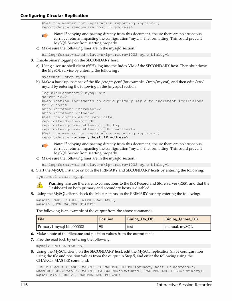
#Set the master for replication reporting (optional)report-host= <secondary host IP address>
Note: If copying and pasting directly from this document, ensure there are no erroneouscarriage returns impacting the configuration "my.cnf" file formatting. This could preventMySQL Server from starting properly.
c) Make sure the following lines are in the mysqld section:
binlog-format=mixed slave-skip-errors=1032 sync_binlog=13. Enable binary logging on the SECONDARY host.
a) Using a secure shell client (SSH), log into the Index VM of the SECONDARY host. Then shut downthe MySQL service by entering the following :
systemctl stop mysqlb) Make a back-up instance of the file /etc/my.cnf (for example, /tmp/my.cnf), and then edit /etc/
my.cnf by entering the following in the [mysqld] section:
log-bin=Secondary2-mysql-binserver-id=2#Replication increments to avoid primary key auto-increment #collisions for 2 hostsauto_increment_increment=2auto_increment_offset=2#Set the db/tables to replicatereplicate-do-db=ipcr_dbreplicate-ignore-table=ipcr_db.logreplicate-ignore-table=ipcr_db.heartbeats#Set the master for replication reporting (optional)report-host= <primary host IP address>
Note: If copying and pasting directly from this document, ensure there are no erroneouscarriage returns impacting the configuration "my.cnf" file formatting. This could preventMySQL Server from starting properly.
c) Make sure the following lines are in the mysqld section:
binlog-format=mixed slave-skip-errors=1032 sync_binlog=14. Start the MySQL instance on both the PRIMARY and SECONDARY hosts by entering the following:
systemctl start mysqlWarning: Ensure there are no connections to the ISR Record and Store Server (RSS), and that theDashboard on both primary and secondary hosts is disabled.
5. Using the MySQL client, check the Master status on the PRIMARY host by entering the following:
mysql> FLUSH TABLES WITH READ LOCK; mysql> SHOW MASTER STATUS;The following is an example of the output from the above commands.
File Position Binlog_Do_DB Binlog_Ignore_DB
Primary1-mysql-bin.000002 98 test manual, mySQL
6. Make a note of the filename and position values from the output table.7. Free the read lock by entering the following:
mysql> UNLOCK TABLES;8. Using the MySQL client, on the SECONDARY host, edit the MySQL replication Slave configuration
using the file and position values from the output in Step 5, and enter the following using theCHANGE MASTER command:
RESET SLAVE; CHANGE MASTER TO MASTER_HOST='<primary host IP address>', MASTER_USER='repl', MASTER_PASSWORD='n3wf0und', MASTER_LOG_FILE='Primary1-mysql-bin.000002', MASTER_LOG_POS=98;
Configuring Circular Replication
116 Interactive Session Recorder

9. Start the Slaves & ensure there are no errors in the "MySQL logs" by entering the following:
mysql> START SLAVE;10. Check the Master status on the SECONDARY host by entering the following:
mysql> FLUSH TABLES WITH READ LOCK; mysql> SHOW MASTER STATUS; The following is an example of the output from the above commands.
File Position Binlog_Do_DB Binlog_Ignore_DB
Secondary2-mysql-bin.000002 98 test manual, mySQL
11. Make a note of the filename and position values from the output table.12. Free the read lock by entering the following:
mysql> UNLOCK TABLES;13. Using the MySQL client, on the PRIMARY host, edit the MySQL replication Slave configuration using
the filename and position values from the output in Step 10 (from the SECONDARY host), and enterthe following using the CHANGE MASTER command:
RESET SLAVE; CHANGE MASTER TO MASTER_HOST='<secondary host IP address>', MASTER_USER='repl', MASTER_PASSWORD='n3wf0und', MASTER_LOG_FILE='Secondary2-mysql-bin.000002', MASTER_LOG_POS=98; START SLAVE;The following commands, run on each host, display the current replication status. To improve theformatting, append the command with \G.
mysql>SHOW MASTER STATUS \G mysql>SHOW SLAVE STATUS \G
Configuring Database FailoverTo edit the configuration on the ISR API and Archival deployments to include database failover:
1. Using a secure shell (SSH) client, log into the RSS host/s using a user name and password.2. To add the secondary database IP address to the API configuration, edit the following file.
/var/lib/tomcat/webapps/IsrApi/WEB-INF/web.xml3. Using the arrow keys to navigate the file and edit the following line with the relevant IP addresses:
<context-param> <param-name>connectionString</param-name> <param-value>jdbc:mysql://169.254.1.50,<secondary_host_IP>/ipcr_db</param-value> <description>MsSQLX connection URI</description> </context-param>
4. Save your changes to the file.5. Restart the application server by performing the following:
systemctl restart tomcat6. If required, verify successful failover between the PRIMARY and SECONDARY servers.
Configuring Circular Replication
Interactive Session Recorder 117

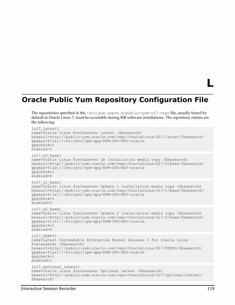
LOracle Public Yum Repository Configuration File
The repositories specified in the /etc/yum.repos.d/public-yum-ol7.repo file, usually found bydefault in Oracle Linux 7, must be accessible during ISR software installations. The repository entries arethe following:
[ol7_latest]name=Oracle Linux $releasever Latest ($basearch)baseurl=http://public-yum.oracle.com/repo/OracleLinux/OL7/latest/$basearch/gpgkey=file:///etc/pki/rpm-gpg/RPM-GPG-KEY-oraclegpgcheck=1enabled=1[ol7_u0_base]name=Oracle Linux $releasever GA installation media copy ($basearch)baseurl=http://public-yum.oracle.com/repo/OracleLinux/OL7/0/base/$basearch/gpgkey=file:///etc/pki/rpm-gpg/RPM-GPG-KEY-oraclegpgcheck=1enabled=0[ol7_u1_base]name=Oracle Linux $releasever Update 1 installation media copy ($basearch)baseurl=http://public-yum.oracle.com/repo/OracleLinux/OL7/1/base/$basearch/gpgkey=file:///etc/pki/rpm-gpg/RPM-GPG-KEY-oraclegpgcheck=1enabled=0[ol7_u2_base]name=Oracle Linux $releasever Update 2 installation media copy ($basearch)baseurl=http://public-yum.oracle.com/repo/OracleLinux/OL7/2/base/$basearch/gpgkey=file:///etc/pki/rpm-gpg/RPM-GPG-KEY-oraclegpgcheck=1enabled=0[ol7_UEKR3]name=Latest Unbreakable Enterprise Kernel Release 3 for Oracle Linux $releasever ($basearch)baseurl=http://public-yum.oracle.com/repo/OracleLinux/OL7/UEKR3/$basearch/gpgkey=file:///etc/pki/rpm-gpg/RPM-GPG-KEY-oraclegpgcheck=1enabled=1[ol7_optional_latest]name=Oracle Linux $releasever Optional Latest ($basearch)baseurl=http://public-yum.oracle.com/repo/OracleLinux/OL7/optional/latest/$basearch/
Interactive Session Recorder 119

gpgkey=file:///etc/pki/rpm-gpg/RPM-GPG-KEY-oraclegpgcheck=1enabled=0[ol7_addons]name=Oracle Linux $releasever Add ons ($basearch)baseurl=http://public-yum.oracle.com/repo/OracleLinux/OL7/addons/$basearch/gpgkey=file:///etc/pki/rpm-gpg/RPM-GPG-KEY-oraclegpgcheck=1enabled=0[ol7_UEKR3_OFED20]name=OFED supporting tool packages for Unbreakable Enterprise Kernel on Oracle Linux 7 ($basearch)baseurl=http://public-yum.oracle.com/repo/OracleLinux/OL7/UEKR3_OFED20/$basearch/gpgkey=file:///etc/pki/rpm-gpg/RPM-GPG-KEY-oraclegpgcheck=1enabled=0priority=20[ol7_MySQL56]name=MySQL 5.6 for Oracle Linux 7 ($basearch)baseurl=http://public-yum.oracle.com/repo/OracleLinux/OL7/MySQL56/$basearch/gpgkey=file:///etc/pki/rpm-gpg/RPM-GPG-KEY-oraclegpgcheck=1enabled=0[ol7_MySQL55]name=MySQL 5.5 for Oracle Linux 7 ($basearch)baseurl=http://public-yum.oracle.com/repo/OracleLinux/OL7/MySQL55/$basearch/gpgkey=file:///etc/pki/rpm-gpg/RPM-GPG-KEY-oraclegpgcheck=1enabled=0[ol7_spacewalk22_client]name=Spacewalk Client 2.2 for Oracle Linux 7 ($basearch)baseurl=http://public-yum.oracle.com/repo/OracleLinux/OL7/spacewalk22/client/$basearch/gpgkey=file:///etc/pki/rpm-gpg/RPM-GPG-KEY-oraclegpgcheck=1enabled=0
Oracle Public Yum Repository Configuration File
120 Interactive Session Recorder

![[XLS]minsvyaz.ruminsvyaz.ru/common/upload/docs/2007061917193vq.xls · Web viewINTRALINK IDR-38 INTRALINK ISR-71 INTRALINK ISR-81 INTRALINK ISR-13 INTRALINK ISR-15 INTRALINK ISR-18](https://img.pdfslide.net/doc/110x75/5b1d3ffb7f8b9acf678b6c15/xls-web-viewintralink-idr-38-intralink-isr-71-intralink-isr-81-intralink-isr-13.jpg)