Embed Size (px)
Citation preview
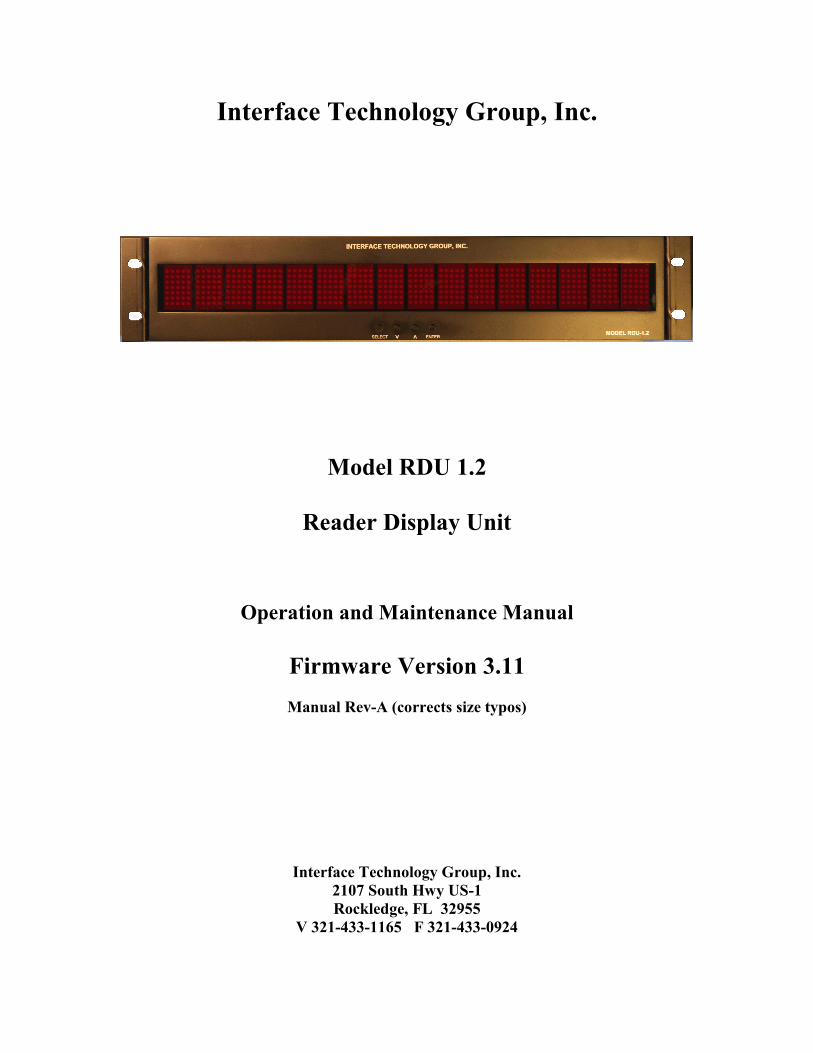
Interface Technology Group, Inc.
Model RDU 1.2
Reader Display Unit
Operation and Maintenance Manual
Firmware Version 3.11
Manual Rev-A (corrects size typos)
Interface Technology Group, Inc.
2107 South Hwy US-1
Rockledge, FL 32955
V 321-433-1165 F 321-433-0924
Specifications:
Power Input:…………………………. 90 – 265 VAC 47-470 Hz.
…………………………IEC Input connector 10W Nominal
Fuse:…………………………….…….1 Amp
Dimensions:………………….……… 19” Wide X 3.50” High (2 RU) X 5.0” Deep
Weight:……………………….……….4.0 Pounds
Operating Environment:…………… 32°°°° F to 100°°°° F, 0 – 95% RH Non condensing
Signal Inputs:
IRIG-B, CS-3 or MILA Modulated code. 109-64 multiplexed code can be read with
an optional 109-64 board. 100 mV to 10 V P-P. 10K ohm Input Impedance. Isolated
BNC Connector with transformer isolation.
CS-524X or CS-5X4 at 4800, 9600, or 19.2K baud, or CS-5259 at 38.4 KB.
Automatic baud rate detection. RS-422 input on Twinax and DB-9 Female
connector.
Signal Outputs:
CS-5XXX buffered output RS-422 on DB-9 Female connector.
DB-9 Female connector – First motion (MLO) relay contacts. N.O. and N.C.
contacts are available.
Ethernet port:
A 10-100 Base T port for control and status.
QUICK START INSTRUCTIONS
In order to get started quickly without reading the entire manual, a quick start lesson is
provided here.
With the RDU-1.2 turned on, pressing the “Select” button will allow the user to scroll
through the available modes or functions. When the desired mode is displayed, pressing
“Enter” will select the mode desired and present a drill down menu of options within that
mode. Generally, the options can be modified by the “Up” and “Down” buttons until the
desired option is displayed. Pressing the “Enter” button will select that option. At the end
of the drill down menus, the final “Enter” button press will cause the RDU-1.2 to store all
parameters and begin to display the mode selected.
Overview:
The model RDU-1.2 reads CS-524X, CS-5X4, CS-5259 and analog signals IRIG-B, CS-
3, MILA, and optionally 109-64 and displays these signals on a 16 digit alpha numeric
dot matrix display.
The RDU-1.2 is capable of reading count and time codes as well as displaying any 16
digit ASCII text message. All settings including the displayed text (in text mode) are
stored in non-volatile EEPROM memory.
The RDU-1.2 will read CS-524X and display either the EC (Event Count) field or the LT
(Launch Time) field. The RDU will also read CS-5259 and display EC, LT or TAG
information.
When CS-5X4 is selected, a specified identifier may be entered for use in selecting the
desired count. A scan function is also available. When in the scan mode, all available
identifiers are displayed in sequence. Pressing the enter button will instantly select the
displayed identifier and begin to display the desired count.
Either CS524X or CS-5X4 or CS-5259 may be displayed with decimal seconds or
without. All signals will be read with automatic baud rate detection.
Colons are displayed optionally. The display may be configured to display accumulated
seconds in both CS-5 and IRIG-B display modes.
When the “P” character changes to an “A” character in the CS-5 stream, a relay will
close. Both normally open and normally closed contacts are available on the rear panel.
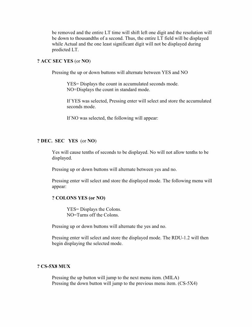
If the display is set to display the LT field, when the LT is Predicted, a “P” will be
displayed and the predicted time will have resolution down to hundredths of a second.
When the LT is Actual (there has been a missile lift off), the “P” will be removed and the
entire LT time will shift left one digit and the resolution will be down to thousandths of a
second. Thus, the entire LT field will be displayed while Actual and the one least
significant digit will not be displayed during predicted LT.
The model RDU-1.2 will also read IRIG-B, CS-3 and MILA. In addition, an identifier
may be selected and displayed on the LED screen. For IRIG-B, an offset of up to plus or
minus 12 hours in ½ hour increments may be selected.
Leading zero blanking may be selected. There are two modes available. First is straight
left to right leading zero suppression. Second is left to right per group leading zero
suppression. Per group is defined as days, hours, minutes, and seconds. In the first case,
the colons are extinguished as necessary. In the second case, colons will remain on.
The brightness of the display may be adjusted and the brightness level stored in
EEPROM.
The current leap year identification may be entered so as to properly calculate offset
times.
All mode changes and brightness changes will be stored in non-volatile memory. The unit
will enter into the last selected mode when it is powered up and begin displaying the
selected count.
Operation:
Connect a suitable AC mains power source to the rear IEC connector. Connect a CS-
524X signal or a CS-5X4 signal to the DB-9 or Twinax RS-422 input connector.
Connect an Analog modulated signal to the isolated BNC connector. Turn on the AC
power switch on the rear panel.
The RDU-1.2 will power up and read the last set-up that was entered. If a signal is
available, the unit will display that count (or time) on the display.
Display Details:
The display is set-up by means of an on screen menu system. The select button steps
through each of the menu screens. When the desired screen (or mode) is seen, pressing
the enter button will either execute that option or drill down to the next level menu. For
each menu level if there are options available, the up or down arrow will change the
option. When the desired option is seen, pressing enter will execute that option.
Whatever options or selections are made, they will be stored in memory and re-called on
power up. Thus, once set-up, the unit may be turned off and on again without having to
do anything.
When the unit is turned on, if there is no signal available to display, the unit will display
the following:
MODE Display
IRIG-B ?1111 11 11 1111
CS-3 ?3333 33 33 3333
IRIG-B ?1111 11 11 1111
CS-5 ?222222222222222
CS-5X4 ?222222222222222
CS-5X8 MUX ?222222222222222
MILA ?4444 44 44 4444
109-64 9 99 99 99
Pressing the Select button will Cause the following:
? IRIG-B
Pressing the up button will jump to the next menu item. (CS-3)
Pressing the down button will jump to the previous menu item. (VERSION)
Pressing enter will display the available ID characters that may be
assigned. (NONE, A-Z).
The up and down arrows will scroll through the available ID characters.
Pressing enter will select the display ID character and display:
X OFFSET XX.X H
Pressing the up or down buttons will scroll through the available offsets.
(Plus or minus 12 hours in ½ hr increments)
Pressing enter will select the desired offset and display:
? ACC SEC YES (or NO)
Pressing the up or down buttons will alternate between YES and NO
YES= Displays the count in accumulated seconds mode.
NO=Displays the count in standard mode.
If YES was selected, Pressing enter will select and store the
accumulated seconds mode and begin the display mode.
If NO was selected, the following will appear:
? COLONS YES (or NO)
Pressing the up or down buttons will alternate between YES and
NO
YES= Displays the colons.
NO= Turns the colons off.
After pressing Enter, the mode will be stored and the display will
begin.
? CS-3
Pressing the up button will jump to the next menu item. (CS-5)
Pressing the down button will jump to the previous menu item. (IRIG-B)
Pressing enter will display the available ID characters that may be
assigned. (NONE, A-Z).
The up and down arrows will scroll through the available ID characters.
Pressing enter will select CS-3 mode the menu will jump to the EC or LT
Mode selection.
Pressing the up or down button will alternate between EC or LT display mode.
Pressing enter will select and store the currently displayed mode.
IF EC is selected, the menu will jump to the CS-3 ? Accum seconds menu.
IF LT is selected, the menu will jump to the ? Decimal Seconds Menu.
CS-3 Accum seconds
Pressing enter will select the desired mode and display:
? ACC SEC YES (or NO)
Pressing the up or down buttons will alternate between YES and NO
YES= Displays the count in accumulated seconds mode.
NO=Displays the count in standard mode.
If YES was selected, Pressing enter will select and store the
accumulated seconds mode and begin the display mode.
If NO was selected, the following will appear:
? COLONS YES (or NO)
Pressing the up or down buttons will alternate between YES and
NO
YES= Displays the colons.
NO= Turns the colons off.

After pressing Enter, the mode will be stored and the display will
begin.
? CS-5
Pressing the up button will jump to the next menu item. (CS-5X4)
Pressing the down button will jump to the previous menu item. (CS-3)
Pressing enter will select CS-5 mode the menu will jump to the EC or LT
Mode selection.
? CS-5X4
Pressing the up button will jump to the next menu item. (CS-5X8 MUX)
Pressing the down button will jump to the previous menu item. (CS-5)
Pressing enter will select CS-5X4 mode and display:
X ID CHAR (where X= the current ID char)
Pressing up or down will scroll though the list of available ID characters
From which to select a CS-5 signal.
Pressing enter will select and store the currently displayed identifier and
go to the EC / LT Menu.
? CS-5 EC (or LT)
Pressing the up or down button will alternate between EC or LT display mode.
This affects both CS-524X and CS-5X4 modes
Pressing enter will select and store the currently displayed mode.
IF EC is selected, the menu will jump to the ? Accum seconds menu.
IF LT is selected, the menu will jump to the ? COLONS YES (or NO) Menu.
A note about displaying the LT field in CS-5. When the LT is Predicted, a “P”
will be displayed and the predicted time will have resolution down to hundredths
of a second. When the LT is Actual (there has been a missile lift off), the “P” will
be removed and the entire LT time will shift left one digit and the resolution will
be down to thousandths of a second. Thus, the entire LT field will be displayed
while Actual and the one least significant digit will not be displayed during
predicted LT.
? ACC SEC YES (or NO)
Pressing the up or down buttons will alternate between YES and NO
YES= Displays the count in accumulated seconds mode.
NO=Displays the count in standard mode.
If YES was selected, Pressing enter will select and store the accumulated
seconds mode.
If NO was selected, the following will appear:
? DEC. SEC YES (or NO)
Yes will cause tenths of seconds to be displayed. No will not allow tenths to be
displayed.
Pressing up or down buttons will alternate between yes and no.
Pressing enter will select and store the displayed mode. The following menu will
appear:
? COLONS YES (or NO)
YES= Displays the Colons.
NO=Turns off the Colons.
Pressing up or down buttons will alternate the yes and no.
Pressing enter will select and store the displayed mode. The RDU-1.2 will then
begin displaying the selected mode.
? CS-5X8 MUX
Pressing the up button will jump to the next menu item. (MILA)
Pressing the down button will jump to the previous menu item. (CS-5X4)
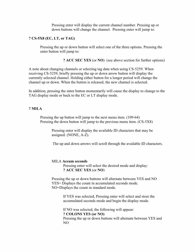
Pressing enter will display the current channel number. Pressing up or
down buttons will change the channel. Pressing enter will jump to:
? CS-5X8 (EC, LT, or TAG)
Pressing the up or down button will select one of the three options. Pressing the
enter button will jump to:
? ACC SEC YES (or NO) (see above section for further options)
A note about changing channels or selecting tag data when using CS-5259. When
receiving CS-5259, briefly pressing the up or down arrow button will display the
currently selected channel. Holding either button for a longer period will change the
channel up or down. When the button is released, the new channel is selected.
In addition, pressing the enter button momentarily will cause the display to change to the
TAG display mode or back to the EC or LT display mode.
? MILA
Pressing the up button will jump to the next menu item. (109-64)
Pressing the down button will jump to the previous menu item. (CS-5X8)
Pressing enter will display the available ID characters that may be
assigned. (NONE, A-Z).
The up and down arrows will scroll through the available ID characters.
MILA Accum seconds
Pressing enter will select the desired mode and display:
? ACC SEC YES (or NO)
Pressing the up or down buttons will alternate between YES and NO
YES= Displays the count in accumulated seconds mode.
NO=Displays the count in standard mode.
If YES was selected, Pressing enter will select and store the
accumulated seconds mode and begin the display mode.
If NO was selected, the following will appear:
? COLONS YES (or NO)
Pressing the up or down buttons will alternate between YES and
NO
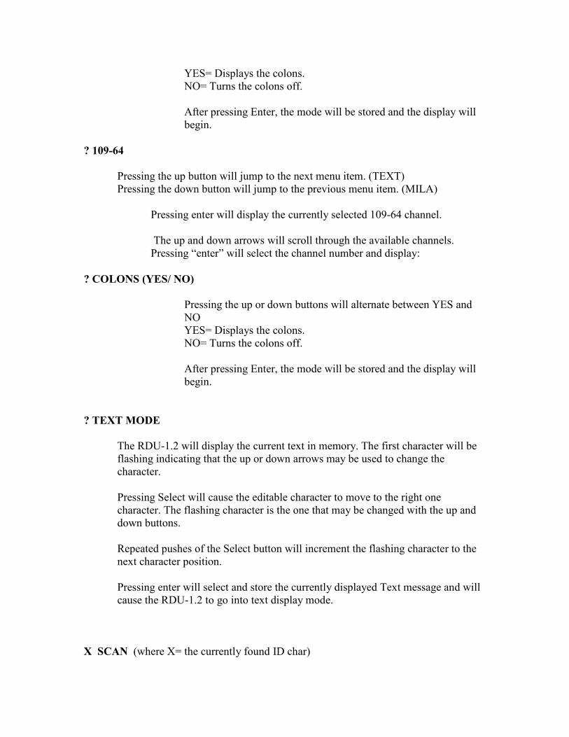
YES= Displays the colons.
NO= Turns the colons off.
After pressing Enter, the mode will be stored and the display will
begin.
? 109-64
Pressing the up button will jump to the next menu item. (TEXT)
Pressing the down button will jump to the previous menu item. (MILA)
Pressing enter will display the currently selected 109-64 channel.
The up and down arrows will scroll through the available channels.
Pressing “enter” will select the channel number and display:
? COLONS (YES/ NO)
Pressing the up or down buttons will alternate between YES and
NO
YES= Displays the colons.
NO= Turns the colons off.
After pressing Enter, the mode will be stored and the display will
begin.
? TEXT MODE
The RDU-1.2 will display the current text in memory. The first character will be
flashing indicating that the up or down arrows may be used to change the
character.
Pressing Select will cause the editable character to move to the right one
character. The flashing character is the one that may be changed with the up and
down buttons.
Repeated pushes of the Select button will increment the flashing character to the
next character position.
Pressing enter will select and store the currently displayed Text message and will
cause the RDU-1.2 to go into text display mode.
X SCAN (where X= the currently found ID char)
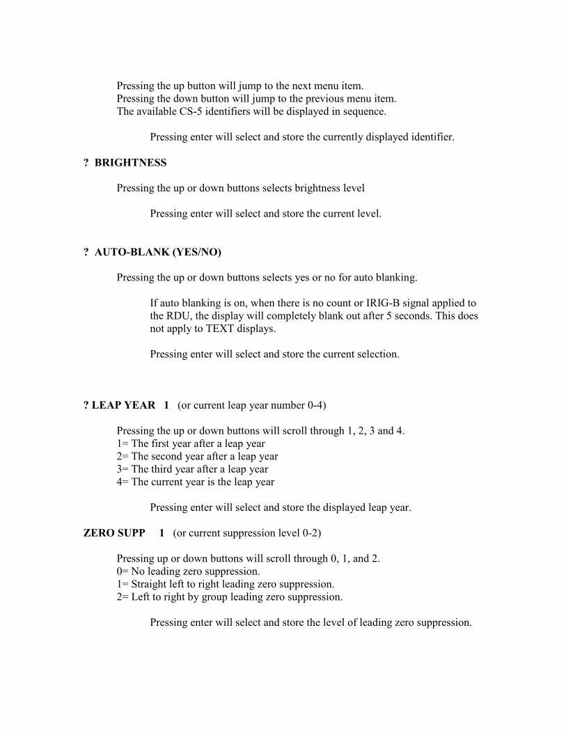
Pressing the up button will jump to the next menu item.
Pressing the down button will jump to the previous menu item.
The available CS-5 identifiers will be displayed in sequence.
Pressing enter will select and store the currently displayed identifier.
? BRIGHTNESS
Pressing the up or down buttons selects brightness level
Pressing enter will select and store the current level.
? AUTO-BLANK (YES/NO)
Pressing the up or down buttons selects yes or no for auto blanking.
If auto blanking is on, when there is no count or IRIG-B signal applied to
the RDU, the display will completely blank out after 5 seconds. This does
not apply to TEXT displays.
Pressing enter will select and store the current selection.
? LEAP YEAR 1 (or current leap year number 0-4)
Pressing the up or down buttons will scroll through 1, 2, 3 and 4.
1= The first year after a leap year
2= The second year after a leap year
3= The third year after a leap year
4= The current year is the leap year
Pressing enter will select and store the displayed leap year.
ZERO SUPP 1 (or current suppression level 0-2)
Pressing up or down buttons will scroll through 0, 1, and 2.
0= No leading zero suppression.
1= Straight left to right leading zero suppression.
2= Left to right by group leading zero suppression.
Pressing enter will select and store the level of leading zero suppression.
? DISPLAY + (YES/NO)
Pressing the up or down buttons selects yes or no for displaying the plus symbol
in a plus count. If “NO” is selected, a space (blank) will be displayed.
Pressing enter will select and store the current selection.
QUIT NO CHANGE
Pressing the up button will jump to the next menu item. (VERSION)
Pressing the down button will jump to the previous menu item. (ZERO SURP)
Pressing enter will exit the menu system without saving changes.
Pressing Select will cause a jump to the ? IRIG_B Menu.
VERSION 3.11 (or the current version)
Pressing the up button will jump to the next menu item. (? IRIG-B)
Pressing the down button will jump to a previous menu item. (ZERO SUPP X)
Pressing enter will exit the menu system and save any changes.
Remote Control:
RS-232 Port:
Remote control of the RDU 1.2 is accomplished through the Ethernet port or via the RS-
232 port on the rear of the unit.
Connecting a computer running a terminal program such as Hyperterminal set up as
9600-N-8-1 allows control and status information to be passed from or to the reader
display unit. A standard straight through cable is required. Only pins 2,3, and 5 are
utilized.
Hitting Enter (C/R) will cause the RDU-1.2 to respond with: RDU-1.2 #XXXX> Where
XXXX is the serial number of the unit.
KEYWORDS:
The following are keywords or words that are used by the RDU-1.2 to control the unit via
remote commands. The keywords may be upper or lower case. The words must be typed
correctly without back spacing or making corrections. Incorrect typing or misunderstood
words are returned as typed followed by a question mark.
STATUS (C/R) Returns the status of the display.
MODE (C/R) Enters into a dialog to control the function of the display.
HELP or ? (C/R) Displays a list of available commands.
Entering the mode command results in a dialog starting with the mode of operation
desired. The currently programmed variable is display and alternate selections are
displayed. If the current variable is desired to stay the same, a (C/R) or Enter may be used
and the next variable will be displayed.
If a mistake is made, hitting the escape key will cause the dialog to move up (or back)
one level. Repeated escape keys can cause the dialog to exit out of command mode.
At the end of the dialog, a question will appear: “Store Program? (Y/N )” Either Y or N
(or ESC) must be entered. If a Y is entered, the operational data will be stored and begin
operation as programmed.
Ethernet Port:
The Ethernet port may be used in exactly the same way as the RS-232 port by using a
Telnet program to connect to the IP address of the RDU 1.2. The IP address of the port
may be set to a fixed address or by dynamically set through DHCP. The factory default is
DHCP mode. The default telnet port is 10001. The default XPORT control port is 9999.
The Ethernet port module is a Lantronix XPort module. It is recommended that the
Lantronix web site WWW.lantronix.com be consulted to understand how to use the
interface. A utility program from Lantronix called Device Installer (current version
4.1.0.9) should be downloaded and used to set up the IP address. This utility program
makes it easy to set up the parameters of the XPort device to customize it for the
particular network application.
Note that the XPort must be configured to provide a Modem Ctrl Out (DCD) signal on
configurable pin (CP) #1 (input, active low). This is necessary for the RDU-1.2 to switch
control ports from the RS-232 to the ethernet port when a telnet session is established.
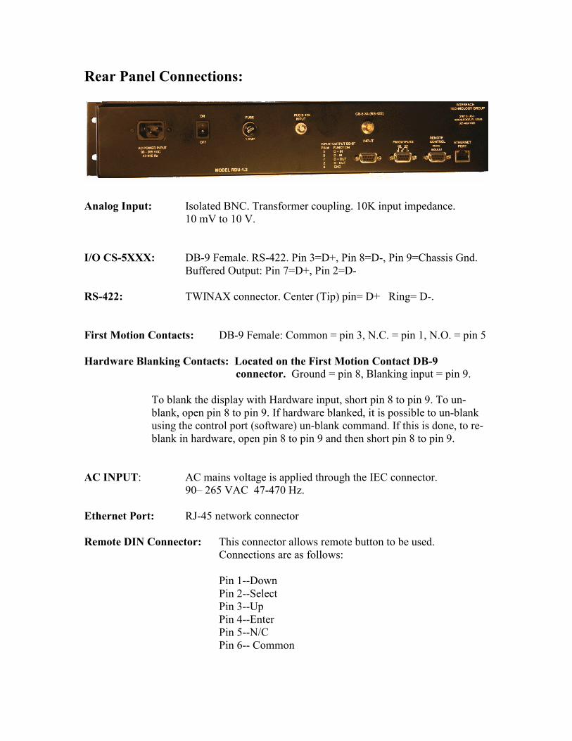
Rear Panel Connections:
Analog Input: Isolated BNC. Transformer coupling. 10K input impedance.
10 mV to 10 V.
I/O CS-5XXX: DB-9 Female. RS-422. Pin 3=D+, Pin 8=D-, Pin 9=Chassis Gnd.
Buffered Output: Pin 7=D+, Pin 2=D-
RS-422: TWINAX connector. Center (Tip) pin= D+ Ring= D-.
First Motion Contacts: DB-9 Female: Common = pin 3, N.C. = pin 1, N.O. = pin 5
Hardware Blanking Contacts: Located on the First Motion Contact DB-9
connector. Ground = pin 8, Blanking input = pin 9.
To blank the display with Hardware input, short pin 8 to pin 9. To un-
blank, open pin 8 to pin 9. If hardware blanked, it is possible to un-blank
using the control port (software) un-blank command. If this is done, to re-
blank in hardware, open pin 8 to pin 9 and then short pin 8 to pin 9.
AC INPUT: AC mains voltage is applied through the IEC connector.
90– 265 VAC 47-470 Hz.
Ethernet Port: RJ-45 network connector
Remote DIN Connector: This connector allows remote button to be used.
Connections are as follows:
Pin 1--Down
Pin 2--Select
Pin 3--Up
Pin 4--Enter
Pin 5--N/C
Pin 6-- Common
Power Supply:
The RDU uses a “Universal Input” switching power supply for cool and reliable
operation. The power supply accepts any common voltage between 90 and 265 VAC or
100 to 370 Volts DC without any adjustment. A separate line filter is built into the RDU-
1.2 for an additional measure of EMI suppression. The Power supply used is UL listed
and approved by several other agencies.
Routine Maintenance:
Remove dust from the cabinet when it accumulates. The front panel may cleaned with a
soft cotton cloth. Use only a small amount of mild soap and water solution to dampen the
cloth if necessary.
No routine checks or adjustments are required.


![show access-group mode interface - Cisco€¦ · show access-group mode interface [interface interface-number] Syntax Description Defaults This command has no default settings. Command](https://img.pdfslide.net/doc/110x75/605498174543517f51389fe7/show-access-group-mode-interface-cisco-show-access-group-mode-interface-interface.jpg)