Embed Size (px)
Citation preview

Interim Advice Note 149/11 Existing Motorway Minimum Requirements
IAN 149/11 Page 1 of 44 July 11
INTERIM ADVICE NOTE 149/11 Existing Motorway Minimum Requirements Summary This document provides amendments and additional relaxations to the DMRB standards listed below, allowing greater flexibility when dealing with the constraints associated with enhancing existing elements of the Motorway network. Instructions for Use This document is supplementary to: TD9 Highway Link Design TD22 Layout of Grade Separated
Junctions TD27 Cross-Sections and Headrooms TD46 Motorway Signalling and supersedes: IAN 87/07 The Provision of Signal Gantries
for Motorways with Four or More Running Lanes

Interim Advice Note 149/11 Existing Motorway Minimum Requirements
IAN 149/11 Page 2 of 44 July 11
Table of Contents 1 Introduction 2 Highway Link Design 3 Layout of Grade Separated Junctions 4 Cross-Sections and Headrooms 5 Motorway Signalling 6 Contacts 7 References
Annex A: Existing Motorway Minimum Requirements in English DBFO schemes
Interim Advice Note 149/11 Existing Motorway Minimum Requirements
IAN 149/11 Page 3 of 44 July 11
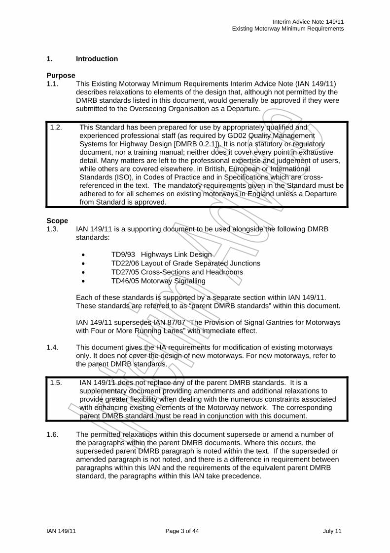
1. Introduction Purpose 1.1. This Existing Motorway Minimum Requirements Interim Advice Note (IAN 149/11)
describes relaxations to elements of the design that, although not permitted by the DMRB standards listed in this document, would generally be approved if they were submitted to the Overseeing Organisation as a Departure.
1.2. This Standard has been prepared for use by appropriately qualified and experienced professional staff (as required by GD02 Quality Management Systems for Highway Design [DMRB 0.2.1]). It is not a statutory or regulatory document, nor a training manual; neither does it cover every point in exhaustive detail. Many matters are left to the professional expertise and judgement of users, while others are covered elsewhere, in British, European or International Standards (ISO), in Codes of Practice and in Specifications which are cross-referenced in the text. The mandatory requirements given in the Standard must be adhered to for all schemes on existing motorways in England unless a Departure from Standard is approved.
Scope 1.3. IAN 149/11 is a supporting document to be used alongside the following DMRB
standards:
TD9/93 Highways Link Design TD22/06 Layout of Grade Separated Junctions TD27/05 Cross-Sections and Headrooms TD46/05 Motorway Signalling
Each of these standards is supported by a separate section within IAN 149/11. These standards are referred to as “parent DMRB standards” within this document. IAN 149/11 supersedes IAN 87/07 “The Provision of Signal Gantries for Motorways with Four or More Running Lanes” with immediate effect.
1.4. This document gives the HA requirements for modification of existing motorways
only. It does not cover the design of new motorways. For new motorways, refer to the parent DMRB standards.
1.5. IAN 149/11 does not replace any of the parent DMRB standards. It is a supplementary document providing amendments and additional relaxations to provide greater flexibility when dealing with the numerous constraints associated with enhancing existing elements of the Motorway network. The corresponding parent DMRB standard must be read in conjunction with this document.
1.6. The permitted relaxations within this document supersede or amend a number of
the paragraphs within the parent DMRB documents. Where this occurs, the superseded parent DMRB paragraph is noted within the text. If the superseded or amended paragraph is not noted, and there is a difference in requirement between paragraphs within this IAN and the requirements of the equivalent parent DMRB standard, the paragraphs within this IAN take precedence.

Interim Advice Note 149/11 Existing Motorway Minimum Requirements
IAN 149/11 Page 4 of 44 July 11
1.7. The parent DMRB standards listed in paragraph 1.3 are current at the time of writing this IAN. Should future versions of the above standards be developed whilst IAN 149/11 is still in use, IAN 149/11 will need to be updated accordingly and reissued. If there is a discrepancy between the current version of the parent DMRB standard, and the version referenced in IAN 149/11, an appropriate judgement on the application of IAN 149/11 must be made and recorded in an auditable manner, in the Design Strategy Record.
Implementation
1.8. IAN 149/11 must be used on all schemes on existing trunk roads in England where motorway regulations apply.
1.9. This Advice Note should be used forthwith for all trunk road schemes currently
being prepared provided that, in the opinion of the Overseeing Organisation, this would not result in significant additional expense or delay progress.
1.10. IAN 149/11 has been developed for use on trunk roads where motorway
regulations apply in England; however the additional relaxations available may provide benefits to other schemes such as improvements to other roads, new build schemes, or projects outside of the Highways Agency. Use of IAN 149/11 on roads other than roads where the motorway regulations apply in England requires approval from the relevant authority.
Safety Management System 1.11. Projects undertaken by the Highways Agency (HA) have to be implemented with an
appropriate level of safety risk management in order to provide road users, road workers and 3rd parties with adequate risk protection. Project safety risk is controlled by deploying an appropriate Safety Management System (SMS), so determining the activities that make up the SMS is important for all projects.
1.12. Application of this IAN is based on fulfilling the Highways Agency requirements for safety risk assessment and management as appropriate for the type of project, through the use of an appropriate Safety Management System. For Managed Motorway projects this would be IAN139/11 Managed Motorways Project Safety Risk Work Instructions.
Design Strategy Record (DSR) 1.13. The Departures from Standard process provides an auditable record of the
decisions made in providing a non-compliant solution. Use of IAN 149/11 will eliminate the need for many of the departures from standard. The DSR provides an auditable record of decisions to reflect the remaining need for an audit trail around Departure from Standard.
1.14. A DSR must be developed as the design progresses, to demonstrate and record
strategic and design constraints and decisions, with supporting evidence, in an auditable manner.
1.15. The DSR should be used to demonstrate the existing accident record and
operational performance has been considered.
Interim Advice Note 149/11 Existing Motorway Minimum Requirements
IAN 149/11 Page 5 of 44 July 11
1.16. Consideration must be given to applying this document and the effects of incorporating the relaxations having weighed the benefits and potential disbenefits.
Departures from Standard 1.17. The intent of IAN 149/11 is to reduce the number of departures from standard;
however in exceptional circumstances departures may still be required. In these instances, the departures should be made against IAN 149/11, not the parent DMRB standard.
1.18. Mandatory sections of this document are contained in boxes. If it is not possible to comply, a suitable Departure from Standard must be agreed with the Overseeing Organisation. The remainder of the document contains advice, explanation and guidance for consideration.

Interim Advice Note 149/11 Existing Motorway Minimum Requirements
IAN 149/11 Page 6 of 44 July 11
2. HIGHWAY LINK DESIGN 2.1. GENERAL 2.1.1. This chapter is to be read in conjunction with TD9/93 (DMRB6.1) Highway Link
Design. Together with TD9, this chapter must be used to derive the Design Speed and the appropriate geometric parameters
i) The following paragraphs in TD9 are amended:
1.6 1.7 3.1 3.2 3.15 4.1
ii) The following paragraphs in TD9 are superseded:
1.24 1.26 2.13 4.13 4.17
2.1.2. This chapter increases the scope of Relaxations provided in TD 9 to allow
consideration of alignment parameter values, and combinations of those values, that would generally be approved if they were put to the Overseeing Organisation as Departure proposals.
2.2. DESIGN SPEED Selection of Design speed 2.2.1. Design Speed must be derived in the manner described in TD9 Paragraphs 1.6
and 1.7, however when applying this document all Design Speeds may be classed as Band B. This amends TD9 Paragraphs 1.6 and 1.7.
Relaxations 2.2.2. The Relaxations below Desirable Minimum in stopping sight distance, horizontal
curvature, vertical crest curves and Absolute Minimum for sag curves described in TD9 Paragraphs 2.8 to 2.13 inclusive, 3.4 to 3.6 inclusive, 4.9 to 4.12 inclusive and 4.14 to 4.16 inclusive may be used in combination. This supersedes TD9 Paragraph 1.24.
2.2.3. The Relaxations below Desirable Minimum in stopping sight distance, vertical
crest curves and Absolute Minimum for sag curves described in TD9 Paragraphs 2.8 to 2.13 inclusive, 4.9 to 4.12 inclusive and 4.14 to 4.16 inclusive may be used on the immediate approaches to junctions. This supersedes TD9 paragraph 1.26.
2.3. SIGHT DISTANCE Relaxations 2.3.1. For all Band B roads where the stopping sight distance is reduced by bridge piers,
bridge abutments, lighting columns, supports for gantries and traffic signs in the verge or central reserve which form momentary obstructions, the scope for Relaxations may be extended by 1 Design Speed step.

Interim Advice Note 149/11 Existing Motorway Minimum Requirements
IAN 149/11 Page 7 of 44 July 11
2.3.2. Long bridge parapets or safety fences or safety barriers on horizontal curves may obscure stopping sight distance to the 0.26m object height, although the appropriate sight distance to the tops of other vehicles, represented by the 1.05m object height, will be obtained above the parapet or safety fence or safety barrier. For Band B roads where the appropriate stopping sight distance to the high object is available in this way, the scope for Relaxation of stopping sight distance for sight lines passing in front of the obstruction to the 0.26m object height may be extended by one Design Speed step.
2.3.3. If Hard Shoulder Running is provided, the design speed used in determining
minimum sight distances in the Hard Shoulder should be appropriate for the anticipated traffic speed under this operating system.
2.3.4. All Relaxations below desirable Minimum stopping sight distance described in
TD9 Paragraphs 2.8 to 2.12 are permitted on the immediate approach to junctions. This supersedes TD9 Paragraph 1.26 and 2.13.
2.4. HORIZONTAL ALIGNMENT
Relaxations 2.4.1. The number of Design steps permitted below Desirable Minimum may be for
Band B roads as described in Paragraph 2.2.1 of this Document.
Road Camber 2.4.2. The existing crossfall or superelevation may be retained unless:
The variation in crossfall for any given cross-section exceeds the limits identified in Paragraph 2.4.4 of this Document
The resultant drainage flow path does not satisfy the assessment required in Paragraph 2.4.7 to 2.4.9 of this Document
The review of the existing operational performance identifies any issues related to crossfall.
This amends TD9 Paragraphs 3.1 and 3.2.
2.4.3. Crossfall and superelevation shall be measured between the outer edges of the
two outside carriageway edge lines, with the exception of the introduction of superelevation described in Paragraph 2.4.4 of this Document.
2.4.4. Crossfall or superelevation must satisfy the following criteria:
The change of angle must not exceed 5%. i.e. a hardshoulder with a 2.5% fall towards the verge adjacent to a carriageway with a 2.5% fall towards the central reserve produces a change of 5% and would be acceptable.
Changes in crossfall that create a sag must take place within hatched markings with solid edge lines.
Where a sag creates a low point the associated surface water flow width must not enter a traffic lane.
A minimum 3m distance must be provided between changes in crossfall or superelevation within any given cross-section.
Adverse camber is not permitted on horizontal radii less than 2000m. Crossfalls may be increased by 0.5% above the requirements of TD9
Table 3 to mitigate excessive depths of water as identified in paragraph 2.4.7 of this document.

Interim Advice Note 149/11 Existing Motorway Minimum Requirements
IAN 149/11 Page 8 of 44 July 11
2.4.5. The implementation of Paragraph 2.4.4 of this Document must be recorded in the DSR.
2.4.6. There may be benefit to the design by introducing a variation in crossfall or
superelevation, as described above, at existing bridges which are to be retained. If so, a Departure from Standard must be submitted to provide a change in crossfall at a lane line to:
provide the maintained headroom (TD27) at an overbridge or; follow the deck cross-section of an underbridge.
Water Depths on Wide Carriageways
2.4.7. TA80 gives guidance for the preparation and assessment of drainage designs for carriageway surfaces to limit depths of water during rain storms. It is based on research into water depths on wide carriageways and must be used on all schemes where the total width of running lanes, including hard shoulder running, is increased.
2.4.8. An alternative method for establishing compliance with TA80 Figure 2.4 is for the
flow path gradient to exceed 0.0007(FPL)2+0.0406(FPL)+0.146, where FPL is the flow path length.
2.4.9. The location of flow paths identified in Paragraphs 2.4.7 to 2.4.8, and the proposed mitigation must be recorded in the DSR.
Transitions
2.4.10. The basic transition length must be no shorter than the existing transition. This amends TD9 Paragraph 3.15.
2.5. VERTICAL ALIGNMENT
Relaxations 2.5.1. The number of Design steps permitted below Desirable Minimum may be for
Band B roads as described in Paragraph 2.2.1 of this Document. 2.5.2. Relaxations below Desirable Minimum vertical curvature and Absolute Minimum
for sag curves are permitted on the immediate approach to junctions, as described in Paragraph 2.2.3 of this Document. This supersedes TD9 Paragraphs 1.26, 4.13 and 4.17.
Gradients 2.5.3. The maximum gradient requirements of TD9 Paragraph 4.1 do not apply when
modifying existing connector roads. This amends TD9 Paragraph 4.1.

Interim Advice Note 149/11 Existing Motorway Minimum Requirements
IAN 149/11 Page 9 of 44 July 11
3. LAYOUT OF GRADE SEPARATED JUNCTIONS 3.1. GENERAL 3.1.1. This chapter is to be read in conjunction with TD22/06 (DMRB6.2.1) Layout of
Grade Separated Junctions. It is supplementary to TD22, but does not supersede it. Together with TD22, it gives requirements and guidance for modification of grade separated junctions and interchanges on motorways.
i) The following paragraphs and figures in TD22 are amended:
2.29 2.30 Figure 2/4.5 2.34 2.46 4.1 4.7 4.16 to 4.19 4.22 4.35
ii) The following paragraphs in TD22 are superseded:
2.35 2.47
3.1.2. This IAN must also be applied where TD22 is augmented by TD39 The Design of Major Interchanges or TD40 Layout of Compact Grade Separated Junctions.
3.1.3. In order to achieve the optimal junction layout on an existing motorway, a balance
should be reached between what is required by TD22 and what is achievable within the scheme constraints, whether physical or financial. This document describes relaxations that can be applied to TD22.
3.2. TRAFFIC FLOWS 3.2.1. A Design Strategy, appropriate to the type of scheme and the local factors, needs
to be agreed with the Overseeing Organisation and recorded in the DSR. 3.3. DESIGNING MERGES AND DIVERGE LAYOUTS
Designing Merges
3.3.1. Hourly flows for the merge and mainline upstream, as determined in Paragraph 3.2.1 of this Document must be inserted in Figure 2/3 MW of TD22 to select a merge layout as shown in Figures 2/4.1 to 2/4.5 of TD22.
3.3.2. The layouts provided in TD22 apply a consistency across the motorway network,
and drivers are familiar with the standard layouts. The provision of a substitute layout that differs from that derived from the use of TD22 Figure 2/3 MW, as described in Paragraphs 3.3.3 and 3.3.4 of this Document, is an acceptable relaxation. This amends TD22 Paragraph 2.29.

Interim Advice Note 149/11 Existing Motorway Minimum Requirements
IAN 149/11 Page 10 of 44 July 11
3.3.3. If the appropriate layout cannot be provided in full within the scheme constraints, the layout may be amended by either of the following methods:
a) The Road Class in TD22 Table 4/3 may be relaxed to the ‘Rural All-
Purpose 120kph’ as described in Paragraphs 3.4.4 and 3.4.5 of this Document. This amends TD22 Paragraph 4.22. The DSR shall record the Road Class adopted for each geometric parameter this relaxation has been applied to:
b) Merge layouts derived from TD22 Figure 2/3 MW may be substituted
as described below:
Layout F may be substituted by Layout E Layout C may be substituted by Layout B or A Layout B may be substituted by Layout A
3.3.4. Layouts E and F both provide lane gains. If the Overseeing Organisation has
determined that no lane gains are to be introduced, Layouts E and F may be substituted as follows:
Layout E may be substituted by Layout B Layout F may be substituted by Layout C or H No departure is required for the use of Layout H. This amends TD22
Paragraph 2.30 and Figure 2/4.5 by removing the requirement for a departure for the use of Layout H.
3.3.5. The layouts derived from TD22 Figure 2/3 MW and any substitute layouts
proposed must be recorded in the DSR. The DSR must also record the constraints on any given layout, justifying the proposal for a substitute layout.
3.3.6. The revised layout may act as a throttle on the merging traffic and the merge
flows should be reduced accordingly for subsequent capacity calculations on downstream elements of the network.
3.3.7. Many existing slip roads are currently 2 lanes wide but do not follow the Layout
C merge layout. If a Layout B or Layout A merge is desirable on a 2 lane slip road, the slip road must be reduced to a single lane using the reduction taper + 50m length prior to the nose as shown in Layout D. The geometric parameters for the reduction taper must be to Table 10-3 of Traffic Signs Manual Chapter 5. From the back of nose onwards, the alternative Layout B or Layout A must be provided.
Designing Diverges
3.3.8. Hourly flows for the diverge and mainline downstream, as determined in Paragraphs 3.2.1 of this Document must be inserted in Figure 2/5 MW of TD22 to select a diverge layout as shown in Figures 2/6.1 to 2/6.4 of TD22.

Interim Advice Note 149/11 Existing Motorway Minimum Requirements
IAN 149/11 Page 11 of 44 July 11
3.3.9. The layouts provided in TD22 apply a consistency across the motorway network, and drivers are familiar with the standard layouts. If the appropriate layout cannot be provided in full within the scheme constraints, the layout may be amended as follows:
a) The Road Class in TD22 Table 4/4 may be relaxed to the ‘Rural All-
Purpose 120kph’ as described in Paragraphs 3.4.6 to 3.4.8 of this Document. The DSR shall record the Road Class adopted for each geometric parameter this relaxation has been applied to. This amends TD22 Paragraph 4.22.
3.3.10. Any other alterations to the layouts derived in Paragraphs 3.3.8 and 3.3.9 of this Document must be agreed by the Overseeing Organisation and submitted as a Departure from IAN 149/11.
3.3.11. Alternative diverge layouts to those derived in accordance with Paragraph 3.3.8
must not be used. A reduced diverge layout, with subsequently reduced capacity, may have an adverse impact on the mainline traffic. Assessment of this impact is beyond the scope of this Document. The principle of substituting layouts, as described for merge layouts in Paragraph 3.3.3, may be considered for amending the diverge layout, however this must be in agreement with the Overseeing Organisation and will be a Departure from Standard.
3.4. GEOMETRIC STANDARDS
Cross-Sections 3.4.1. For the purpose of designing junctions and interchanges, cross-sections for the
mainline and all connector roads are given in TD 27 (DMRB 6.1.2) as amended by Chapter 4 Cross-Sections and Headrooms of this Document. This amends TD22 Paragraph 4.1.
Horizontal and Vertical Alignment
3.4.2. The geometric standards for horizontal and vertical alignment and stopping sight distance for the mainline through grade separated junction and connector roads must be provided in accordance with TD9 (DMRB 6.1.1) as amended by Chapter 2 Highway Link Design of this Document. This amends TD22 Paragraph 4.7.
Sight Distances
3.4.3. On all connector roads, where the stopping sight distance requirements of TD22 cannot be achieved, the existing sight distance must be maintained as a minimum. This amends TD22 Paragraphs 4.16 to 4.19.
Geometric Design Parameters for Merging Lanes
3.4.4. The merge layouts should be designed to TD22, where possible within the scheme constraints whether physical or financial. If the appropriate layout cannot be provided, the Road Class in TD22 Tables 4/3 may be relaxed to the ‘Rural All-Purpose 120kph’, as described below for merge layouts, and the appropriate geometric parameters applied. This amends TD22 Paragraph 4.22. The DSR must record if this relaxation has been applied.
Interim Advice Note 149/11 Existing Motorway Minimum Requirements
IAN 149/11 Page 12 of 44 July 11
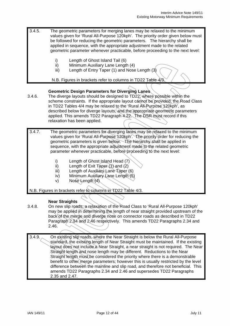
3.4.5. The geometric parameters for merging lanes may be relaxed to the minimum values given for ‘Rural All-Purpose 120kph’. The priority order given below must be followed for reducing the geometric parameters. The hierarchy shall be applied in sequence, with the appropriate adjustment made to the related geometric parameter whenever practicable, before proceeding to the next level:
i) Length of Ghost Island Tail (6) ii) Minimum Auxiliary Lane Length (4) iii) Length of Entry Taper (1) and Nose Length (3)
N.B. Figures in brackets refer to columns in TD22 Table 4/3.
Geometric Design Parameters for Diverging Lanes
3.4.6. The diverge layouts should be designed to TD22, where possible within the scheme constraints. If the appropriate layout cannot be provided, the Road Class in TD22 Tables 4/4 may be relaxed to the ‘Rural All-Purpose 120kph’, as described below for diverge layouts, and the appropriate geometric parameters applied. This amends TD22 Paragraph 4.22. The DSR must record if this relaxation has been applied.
3.4.7. The geometric parameters for diverging lanes may be relaxed to the minimum values given for ‘Rural All-Purpose 120kph’. The priority order for reducing the geometric parameters is given below. The hierarchy shall be applied in sequence, with the appropriate adjustment made to the related geometric parameter whenever practicable, before proceeding to the next level:
i) Length of Ghost Island Head (7) ii) Length of Exit Taper (1) and (2) iii) Length of Auxiliary Lane Taper (6) iv) Minimum Auxiliary Lane Length (5) v) Nose Length (4)
N.B. Figures in brackets refer to columns in TD22 Table 4/3.
Near Straights
3.4.8. On new slip roads, a relaxation of the Road Class to ‘Rural All-Purpose 120kph’ may be applied in determining the length of near straight provided upstream of the back of the merge and diverge nose on connector roads as described in TD22 Paragraph 2.34 and 2.46 respectively. This amends TD22 Paragraphs 2.34 and 2.46.
3.4.9. On existing slip roads, where the Near Straight is below the Rural All-Purpose standard, the existing length of Near Straight must be maintained. If the existing layout does not include a Near Straight, a near straight is not required. The Near Straight length and nose length may be different. Reductions to the Near Straight length must be considered the priority where there is a demonstrable benefit to other merge parameters; however this is usually restricted by the level difference between the mainline and slip road, and therefore not beneficial. This amends TD22 Paragraphs 2.34 and 2.46 and supersedes TD22 Paragraphs 2.35 and 2.47.

Interim Advice Note 149/11 Existing Motorway Minimum Requirements
IAN 149/11 Page 13 of 44 July 11
Weaving Lengths
3.4.10. If the weaving length Lact is less than 2 kilometres, the existing distance between the tip of the merge nose of a junction and the tip of the diverge nose of the following junction must be maintained. This amends TD22 Paragraph 4.35.
3.4.11. In addition, where Lact is less than 2 kilometres, the minimum weaving length Lact
shall be derived from the upper graph in TD22 Figure 4/14 for both urban and rural motorways. If the Lact derived in this manner is not achievable within the scheme constraints, an alternative layout should be considered, such as dedicated lanes between junctions.
3.4.12. The DSR shall record the weaving length philosophy if Lact is less than 2
kilometres.

Interim Advice Note 149/11 Existing Motorway Minimum Requirements
IAN 149/11 Page 14 of 44 July 11
4. CROSS-SECTIONS AND HEADROOMS 4.1. GENERAL 4.1.1. This chapter is to be read in conjunction with TD27/05 (DMRB 6.1.2) Cross
Sections and Headrooms. Together with TD27, it gives details of cross-sections and headrooms to be used on existing motorways.
The following paragraphs in TD27 are superseded:
4.2.1 4.6.2 4.7.2 4.7.6 Table 4-1 Table 4-3 5.5.1 5.6.1 Annex B Table 1, Figure 1, Figure 2 and Figure 3 Annex B 2.1.1 Annex B 2.5.3 Annex B 2.6.2 Annex B 2.9.1
4.1.2. This chapter provides relaxations to the dimensions of the components of the
highway cross-section given in TD27 Figure 4-1a, Figure 4-2a and at structures, which would generally be approved if they were put to the Overseeing Organisation as Departure proposals.
4.2. APPLICATION OF RELAXATIONS TO HIGHWAY CROSS-SECTIONS 4.2.1. The dimensions of the components of the highway cross-section given in TD27
Figure 4-1a and Figure 4-2a may be relaxed to the minimum values identified in Table 4-1 of this Document. This supersedes TD27 Paragraph 4.2.1.
4.2.2. The priority order for relaxations to the highway cross section components is given in Table 4-1 of this Document. The hierarchy must be applied in sequence, subject to Paragraph 4.2.3, with the appropriate adjustment made to the related cross-sectional component whenever practicable, before proceeding to the next level.
4.2.3. The relaxations proposed in Table 4-1 of this Document may be omitted from
the priority hierarchy for strategic reasons over long lengths of the scheme. Any strategic constraints that would prevent a hierarchal step being implemented shall be recorded in the DSR. For example, should there be no opportunity to reduce central reserve width, the relevant steps in Table 4-1 of this Document can be omitted, and the constraint on central reserve width recorded.
4.2.4. Similarly, for local constraints, the relaxations proposed in Table 4-1 of this
Document may be omitted from the priority hierarchy locally over short lengths for short lengths (i.e. less than 100m in length, exclusive of tapers). Any local constraints that would prevent a hierarchal step being implemented shall be recorded in the DSR. For example, should there be a local feature preventing a relaxation in the central reserve width, the relevant steps in Table 4-1 of this

Interim Advice Note 149/11 Existing Motorway Minimum Requirements
IAN 149/11 Page 15 of 44 July 11
Document can be omitted over the length of the local feature, and the constraint on central reserve width recorded.
4.2.5. The length of transition from one cross-section to another should be sufficient for drivers to smoothly follow the alignment of the lane lines and edge lines ahead and to negotiate and adjust position relative to vehicles in the adjacent lanes. Changes in direction must be smooth and curved.
4.2.6. To avoid sharp deviations, no lane lines shall taper at angles steeper than
1:100. This supersedes TD27 Table 4-3. 4.2.7. Any further relaxation below the minimum values stated in Table 4-1 of this
Document is a Departure from Standard.
4.2.8. Table 4-1 of this Document supersedes TD27 Annex B Table 1, Figure 1 and
Paragraph 2.1.1. 4.2.9. The following paragraphs deal with the provision and width of highway cross-
section components and give guidance on the application of Table 4-1 of this Document.

Interim Advice Note 149/11 Existing Motorway Minimum Requirements
IAN 149/11 Page 16 of 44 July 11
Lane
w
idth
s
Pav
ed
wid
th
Wid
th
betw
een
face
s of
V
RS
Har
d sh
ould
er to
ha
rd
shou
lder
w
idth
R
ange
Prio
rity
Ord
er
Des
crip
tion
Nea
rsid
e V
erge
(m
)
Nea
rsid
e S
etba
ck t
o ba
ck o
f HS
/EA
(m
)
Har
dsho
ulde
r (H
S)
or
Em
erge
ncy
Acc
ess
(EA
) w
idth
(m
)
D3M
(m
)
D4M
(m
)
Offs
ide
setb
ack
(m)
Offs
ide
hard
strip
(m
)
Cen
tral
res
erve
(in
c ha
rd s
trip
s) (
m)
D3M
(m
)
D4M
(m
)
D3M
(m
)
D4M
(m
)
D3M
(m
)
D4M
(m
)
TD 27 Standard Provision (i) (ii)
1.5 0.60 3.30 11.00 14.70 1.20 0.70 4.50 15.00 18.70 16.10 19.80 33.10 40.50
1 Reduced verge As necessary to accommodate
equipment 0.60 3.30 11.00 14.70 1.20 0.70 4.50 15.00 18.70 16.10 19.80 33.10 40.50
2 Reduced central Reserve
(iii) 0.60 3.30 11.00 14.70 1.00 0.70 3.40 15.00 18.70 15.90 19.60 32.00 39.40
A
3 Reduced setback to
nearside VRS 0.00 3.30 11.00 14.70 1.00 0.70 3.40 15.00 18.70 15.30 19.00 32.00 39.40
4 Reduced lane widths (iv) 0.00 3.30 10.50 13.95 1.00 0.70 3.40 14.50 17.95 14.80 18.25 31.00 37.90
5 Reduced lane widths,
reduced central reserve (v) (vi)
0.00 3.30 10.50 13.95 1.00 0.70 3.00 14.50 17.95 14.80 18.25 30.60 37.50
6 Reduced hard shoulder
(vii) 0.00 3.00 10.50 13.95 1.00 0.70 3.00 14.20 17.65 14.50 17.95 30.00 36.90
7 Reduced central reserve
(vi) 0.00 3.00 10.50 13.95 1.00 0.70 2.60 14.20 17.65 14.50 17.95 29.60 36.50
8 Reduced EA width 0.00 2.5 10.50 13.95 1.00 0.70 2.60 13.70 17.15 14.00 17.45 28.60 35.50
No
Dep
artu
res
Req
uire
d
B
9 Reduced EA width 0.00 2.00 10.50 13.95 1.00 0.70 2.60 13.20 16.65 13.50 16.95 27.60 34.50
Long
er le
ngth
s re
quire
C
CT
V
10 Reduced lane width
As necessary to accommodate
above and below ground
equipment
0.00 2.00 NA 13.60 1.00 0.70 2.60 NA 16.30 NA 16.60 NA 33.80
Dep
artu
re
rout
e re
quire
d
C
11 Reduced EA width (viii) 0.00
(At structures) 0.30 0.70 NA 13.60 1.00 0.70 2.60 NA 15.00 NA 15.60 NA 31.20
Long
er le
ngth
s re
quire
ov
erhe
ad la
ne
cont
rol,
CC
TV
e
tc
Onl
y us
ed w
here
exi
stin
g co
nstr
aint
s re
stric
t hig
her
hier
arch
y st
ep
30%
max
leng
th o
f dis
cont
inuo
us
hard
sho
ulde
r be
twee
n ea
ch
junc
tion
= reduced dimension compared to next highest hierarchy
i. TD 27/05 4.11.13 allows relaxation in NS setback to 0.45m when VRS needs to be positioned away from an embankment for foundation support ii. TD 27/05 4.11.13 allows relaxation in offside setback to 1.0m at existing roads with physical constraints where it would be difficult to provide the desirable value iii. Minimum for current temporary traffic sign provision iv. D3M 10.50m lane widths 3.65m, 3.55m, 3.30m D4M lane widths L1 - 3.65m, L2 - 3.60m, L3 - 3.40m, L4 – 3.30m v. Or minimum central reserve available if greater than 3.0m vi. Consideration to be given to temporary signing provision upstream of an area with a narrow central reserve vii. D4M 13.60m lane width L1 - 3.5m, L2 - 3.4m, L3 – 3.4m, L4 – 3.3m (IAN 111 gives minimum 13.6m lane width L1 – 3.4m, L2 – 3.5m, L3 – 3.5m, L4 – 3.2m) viii. Minimum 1.0m setback to VRS required. Elsewhere this is included in EA width, but Priority 11 reduces EA below 1m Consideration needs to be given to the removal of ghosting at existing lane line locations Consideration needs to be given to pavement construction joint / new wheel track location. Provide new surfacing across full lane width for each lane encompassing carriageway widening.
Table 4-1: Hierarchy of reduced cross-sections of widening for D3 and D4 on existing rural motorways.

Interim Advice Note 149/11 Existing Motorway Minimum Requirements
IAN 149/11 Page 17 of 44 July 11
4.3. VERGES (Priority 1 in Table 4-1) 4.3.1. Minimum verge widths for verges are given in Table 4-1, Priority 1. This
supersedes TD27 Paragraphs 4.7.2 and 4.7.6.
4.3.2. Relaxation of the width of verges to the minimum required to accommodate equipment shall be the first consideration in reducing cross section width.
4.3.3. Provision for ERT’s and NMU access must be made where a local need has
been identified and agreed with the Overseeing Organisation. The level of need shall be recorded in DSR.
4.3.4. The application of Table 4-1 of this Document with regard to verge width
provision shall be recorded in the DSR.
4.4. CENTRAL RESERVES (Priority 2, 5 and 7 in Table 4-1) 4.4.1. Minimum central reserve widths are given in Table 4-1, Priority 2, 5 and 7. This
supersedes TD27 Paragraph 4.6.2. 4.4.2. The relaxations in central reserve width proposed in Table 4-1 of this Document
may be omitted from the priority hierarchy for strategic reasons over the length of the scheme or locally over short lengths, as described in Paragraphs 4.2.4 and 4.2.5 of this Document.
4.4.3. Should the central reserve width be reduced to 3.4m or less, consultation must be undertaken with Overseeing Organisation in relation to reduced central reserve widths and the impact on maintenance operations. The DSR shall record that this consultation has been undertaken.
4.4.4. Relaxation in the central reserve width must allow sufficient width to
accommodate any relevant equipment, and appropriate working widths for the VRS. Allowance for construction tolerance of VRS and off-side lane markings shall be made within the Design, in the determining the central reserve width.
4.4.5. The application of Table 4-1 of this Document with regard to central reserve
width relaxation shall be recorded in the DSR.
4.5. VRS SETBACK (Priority 3 in Table 4-1) 4.5.1. The minimum dimensions to be used for set-back are given in Table 4-1,
Priority 3. This supersedes TD27 Table 4-1.
4.5.2. The application of Table 4-1 of this Document with regard to VRS set-back relaxation shall be recorded in the DSR.

Interim Advice Note 149/11 Existing Motorway Minimum Requirements
IAN 149/11 Page 18 of 44 July 11
Figure 4-1 D3M & D4M Traffic Lane Widths
0.2 Edge line
VRS VRS 0.1
Lane line
0.2 Edge line
0.1 Lane line
0.1 Lane line
Lane 1 (L1) Lane 2 (L2) Lane 4 (L4) Lane 3 (L3)
Berm (A)
Slope (B)
Hardshoulder (D)
Carriageway (E)
Verge (C)
Central Reserve
(G)
Hard Strip (F)
Hard Strip (F)
A C D B E F G L1 L2 L4L3
Road Type
Varies Varies
3.3 Varies 13.95
10.50 0.70 2.0 0.70
3.65 3.65
3.60 3.55
3.30 N/A
3.40 3.30
Priority 3 D4M D3M
Varies Varies 0.7 Varies 0.70 1.2 0.70
3.50 3.40 3.40 3.30
Priority 11 D4M Subject to Departure
13.6
Varies 1.5 3.3 Varies 0.70 3.1 0.70
3.65 3.65
3.70 3.70
3.70 3.65
3.65 N/A
TD27/05 D4M D3M
14.70 11.00
Varies Varies
2.0
Varies 13.95
10.50
0.70 1.2 0.70
3.65 3.65
3.60 3.55
3.30 N/A
3.40 3.30
Priority 9 D4M D3M

Interim Advice Note 149/11 Existing Motorway Minimum Requirements
IAN 149/11 Page 19 of 44 July 11
4.6. TRAFFIC LANE WIDTHS (Priority 4 and 10 in Table 4-1) 4.6.1. Minimum traffic lane widths are given in Table 4-1, Priority 4 and 10 and
Figure 4-1 of this Document. 4.6.2. Table 4-1 and Figure 4-1 of this Document provides 3 ranges of minimum lane
widths, with increasing minimum mitigation requirements:
Range Overall Lane widths Comments Range A:
D3M - 11.00m D4M - 14.70m
Range B:
D3M – 11.00m to 10.50m D4M - 14.70m to 13.95m
Facilities for traffic monitoring to be provided in agreement with Overseeing Organisation.
Range C:
D3M N/A D4M 13.95m to 13.60m
Motorway to be managed in agreement with the Overseeing Organisation. The use of Band C minimum Lane Widths is a Departure from Standard
4.6.3. Each Range must be applied in turn before applying further relaxation to lane widths. The application of Table 4-1 of this Document with regard to lane width range selection and mitigation shall be recorded in the DSR.
4.6.4. The minimum lane widths provided in Table 4-1 of this Document are
specifically for proposed D3M and D4M projects. The hierarchy provided in Table 4-1 is applicable to other schemes; however appropriate minimum lane widths for other schemes must be derived on a scheme by scheme basis and submitted as a Departure from Standard.
4.6.5. Where the resultant wheel tracks are within 100mm of existing pavement joints
a strategy for treatment of existing surfacing must be developed in consultation with Overseeing Organisation. The DSR shall record that this consultation has been undertaken.
4.6.6. Priority 4 may be omitted for short lengths (i.e. less than 100m in length,
exclusive of tapers), as described in Paragraph 4.2.4 and 4.2.5 of this Document. Relaxations in the hardshoulder width can be a more practicable solution than reducing lane widths at short obstructions. This supersedes TD27 Annex B Paragraph 2.9.1.
4.6.7. Further reductions in lane width shall require Departures from Standards.

Interim Advice Note 149/11 Existing Motorway Minimum Requirements
IAN 149/11 Page 20 of 44 July 11
4.7. HARDSHOULDERS (Priority 6, 8, 9 and 11 in Table 4-1) 4.7.1. Minimum hardshoulder widths are given in Table 4-1, Priority 6, 8, 9 and 11.
4.7.2. Widths of less than 3.0m shall be regarded as discontinuities and the space must be used to provide an emergency access route only. Any local discontinuity of the hardshoulder must be as short as practicable and marked as shown in Figure 4-2 of this Document. This supersedes TD27 Annex B Figure 2 and Paragraph 2.5.3.
4.7.3. Lengths of discontinuous hardshoulder must be limited to 30% of the relevant
motorway link length. 4.7.4. At discontinuities of the hardshoulder, emergency services can make use of
widths of 2.50m or less for access purposes. Consultation must be undertaken with the emergency services and Overseeing Organisation in relation to reduced hardshoulder / emergency access widths and the impact on maintenance operations. The DSR shall record that this consultation has been undertaken. Further reductions in emergency access width below 2.0m width, shall require Departures from Standards.
4.7.5. Drivers having difficulty merging tend to overrun the slip road into the
hardshoulder. Discontinuities of the hardshoulder after a merge slip road must therefore be avoided. No relaxation below 3.0m is permissible for 300m after the merge taper. Should a reduction in width be required in these areas a Departure from Standard shall be obtained.
4.7.6. Bridges with open side-spans may permit construction of a continuous access
roadway for emergency vehicles behind the pier at a hardshoulder discontinuity. Figure 4-3 of this Document shows a typical layout. This supersedes TD27 Annex B Figure 3 and Paragraph 2.6.2.
4.7.7. The application of Table 4-1 of this Document with regard to hardshoulder
width relaxation shall be recorded in the DSR. 4.8. HIGHWAY CROSS-SECTIONS AT STRUCTURES 4.8.1. At structures the central reserve width may be altered in accordance with
Table 4-1 of this Document as required. This supersedes TD27 Paragraph 5.5.1.
4.8.2. The verge width at structures may be reduced to zero at overbridges. This
supersedes TD27 Paragraph 5.6.1.
4.8.3. The DSR shall record the assessment of vehicle impact load and the suitability for vehicles to run adjacent to piers or abutments. Consultation must be undertaken with Overseeing Organisation in relation with the relevant highway and motorway communications maintenance teams over the routing and maintenance implications for underground equipment past piers or abutments. The DSR shall record that this consultation has been undertaken.
4.8.4. Where a 600mm raised verge is provided at an underbridge, the raised verge
width is excluded from the measurement of a hardshoulder width but can be included in the measurement of an Emergency Access width.


Interim Advice Note 149/11 Existing Motorway Minimum Requirements
IAN 149/11 Page 22 of 44 July 11
5. MOTORWAY SIGNALLING 5.1. General 5.1.1. This chapter is to be read in conjunction with TD46/05 (DMRB 9.1.1)
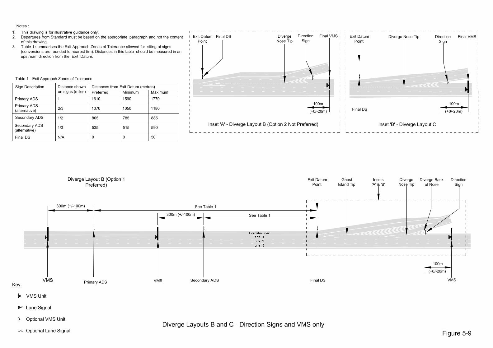
Motorway Signalling. Together with TD46, it provides criteria for siting motorway direction signs and signalling. Figures 5-1 to 5-12 of this Document provide details for layout and signal requirements where Control Signals are provided.
i) The following paragraph in TD46 is amended:
2.9 ii) The following paragraphs and drawings in TD46 are superseded:
3.11 3.14 3.15 3.18 3.23 3.24 3.26 3.27 3.28 Drawing 1 to 6
5.2. Signing and Signalling Provision 5.2.1. This document provides minimum requirements for the three elements of
motorway signalling and associated sign provision:
a) Direction Signing b) Variable Message Signs (VMS) c) Control Signals which comprise either or both of the following
variants:
i) Control Signals that display Variable Mandatory Speed Limit (VMSL),
ii) Lane Signals that display lane control aspects and advisory speed limits.
5.2.2. Direction Signing, Control Signals and VMS may be co-located.
5.3. Entry and Exit Datum Points 5.3.1. The siting of signing and signalling is given relative to entry and exit datum
points for the merge and diverge layouts provided in TD22.
(a) The Entry Datum Points for the TD22 merge layouts are as follows:
i) Layouts A, B C, D, F (Option 2) and H - end of downstream Taper
ii) Layout E – end of Nose. iii) Layouts F (Option 1) and G – end of Ghost Island Tail

Interim Advice Note 149/11 Existing Motorway Minimum Requirements
IAN 149/11 Page 23 of 44 July 11
(b) The Exit Datum Points for the TD22 diverge layouts are as follows:
i) Layouts A, B (Option 1), B (Option 2), C and D (Option 2) - start of upstream Taper
ii) Layout D (Option 1) – 200m upstream of start of Ghost Island Head.
5.4. Direction Signing 5.4.1. Primary and Secondary Advanced Direction Signs (ADS) must only be
provided in a combination of either “1 Mile and 1/2 Mile” or “2/3 Mile and 1/3 Mile”. A Departure from Standard must be sought for any other combination or variation.
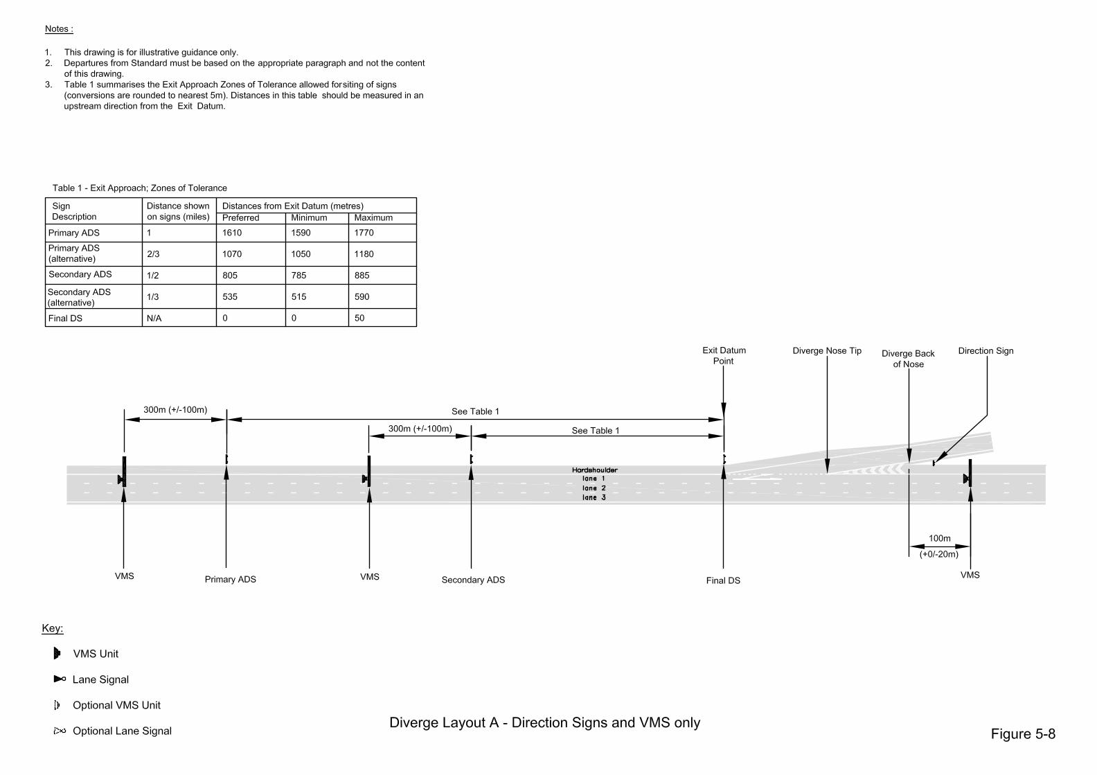
5.4.2. The Primary ADS (with a 1 Mile ADS) must be provided 1,610m upstream of
the Exit Datum Point. If this cannot be achieved due to site constraints, then:
(a) the Primary ADS (with 1 Mile ADS) must be provided between 1,590m and 1,770m upstream of the Exit Datum Point. If this cannot be achieved due to site constraints, then;
(b) the Primary ADS (with 2/3 Mile ADS alternative) must be provided 1,070m upstream of the Exit Datum Point. If this cannot be achieved due to site constraints, then;
(c) the Primary ADS (with 2/3 Mile ADS alternative) must be provided between 1,050m and 1,180m upstream of the Exit Datum Point. If this cannot be achieved due to site constraints, then;
(d) the provision of a Primary ADS with a non-1 Mile ADS or non-2/3 Mile ADS may be considered, subject to acceptance of a Departure from Standard from the Overseeing Organisation.
5.4.3. The Secondary ADS (with 1/2 Mile ADS) must be provided 805m upstream
of the Exit Datum Point. If this cannot be achieved due to site constraints, then:
(a) the Secondary ADS (with 1/2 Mile ADS) must be provided
between 785m and 885m upstream of the Exit Datum Point. If this cannot be achieved due to site constraints, then;
(b) the Secondary ADS (with 1/3 Mile ADS alternative) must be provided at 535m upstream of the Exit Datum Point. If this cannot be achieved due to site constraints, then;
(c) the Secondary ADS (with 1/3 Mile ADS alternative) must be provided between 515m and 590m upstream of the Exit Datum Point. If this cannot be achieved due to site constraints, then;
(d) the provision of a Secondary ADS with a non-1/2 Mile ADS or non-1/3 Mile ADS may be considered, subject to acceptance of a Departure from Standard from the Overseeing Organisation.
5.4.4. Where the Primary ADS or Secondary ADS is provided with ADS showing
other than 1 Mile, 2/3 Mile, 1/2 Mile or 1/3 Mile, subject to the acceptance of a Departure from Standard, the ADS must be provided at the equivalent stated distance from the Exit Datum Point. Where this is not achievable due to site constraints, the sign must be provided at a location between x-20m and x+10% upstream of the Exit Datum Point, where ‘x’ is the appropriate distance.

Interim Advice Note 149/11 Existing Motorway Minimum Requirements
IAN 149/11 Page 24 of 44 July 11
5.4.5. A Final Direction Sign must be provided at the Exit Datum Point. If this
cannot be achieved due to site constraints, then it must be provided up to 50m upstream of the Exit Datum Point.
5.4.6. The philosophy adopted for Direction Signing provision must be recorded in
the DSR.
5.5. Variable Message Signs 5.5.1. Where scheme operational requirements justify a Variable Message Signs
(VMS) system, the following factors must be taken into account:
(a) The First VMS must be provided 300m (+/- 100m) downstream of the Entry Datum Point.
(b) VMS must be provided 300m (+/- 100m) upstream of both the Primary ADS and the Secondary ADS. Where the Primary and Secondary VMS spacing is reduced from 1 mile and 1/2 mile, the distance requirement must be reduced proportionally. At non-strategic junctions, this may be relaxed to allow the VMS to be co-located with the Primary ADS and Secondary ADS.
(c) A VMS must be provided 100m (+0/- 20m) downstream of the diverge back of nose, except where Control Signals are provided as described in Paragraph 5.6.3 of this Document. If this cannot be achieved due to site constraints, the VMS must be provided as close to the 100m maximum as possible.
(d) Where Control Signals are provided, and the distance between Final Sign and Confirmatory Signal is greater than 800m, a VMS must be provided at the Final Sign.
(e) Inter-junction VMS must be spaced between a minimum of 1,200m and up to a maximum of 3,000m. VMS should also be placed in sympathy with the topographical alignment and environmental quality of the whole section of the road and not necessarily at a fixed spacing distance.
(f) An unobstructed sight line must be provided in advance of the downstream VMS for a distance of at least 2/3 (rounded to the highest 50m) of the proposed spacing. The sight line shall be checked between points on the centre line of the right hand traffic lane on right hand bends to the centre of the VMS. On left hand bends the sight line must be checked between points on the centre line of the left hand traffic lane to centre of the VMS. On straights or near straights the shortest visible distance from the centre point of any lane to the centre of the VMS must be checked. VMS must not be placed behind bridges or other features, where the forward visibility of the sign to the driver would be compromised.
This supersedes TD46 Paragraph 3.23.
5.5.2. Intra-Junction VMS
If required by the scheme, an Intra-Junction VMS must be provided if the distance between the First VMS following the junction merge and the preceding VMS is greater than 1,200m.The Intra-Junction VMS should be located as near to the midpoint as possible. The spacing requirements described in Paragraph 5.5.1 of this Document are not applicable intra-junction.

Interim Advice Note 149/11 Existing Motorway Minimum Requirements
IAN 149/11 Page 25 of 44 July 11
5.5.3. Where Control Signals are provided, the VMS and Control Signals may be
co-located. This supersedes TD46 Paragraph 3.18. 5.5.4. The philosophy adopted for VMS provision must be recorded in the DSR.
5.6. Control Signals 5.6.1. Lane Signals must be provided:
a) On motorways with part or full time use of hardshoulder as a running lane;
b) On the approaches to strategic road network interchanges, where a diversion route is available. This supersedes TD 46/05 Paragraph 3.14(b);
c) On the approach to tunnels. This supersedes TD 46/05 Paragraph 3.14(d);
d) On tidal flow schemes with dedicated contra flow lanes. This supersedes TD 46/05 Paragraph 3.14(e).
In all other cases, Lane Signalling is not required. This supersedes TD46 Paragraph 3.11, 3.14, 3.15 and 3.16.
5.6.2. Control Signals that display VMSL must be provided:
a) Where signalling is required to control traffic speeds, or where the business case has determined that the provision of traffic speed control will be beneficial within the next 15 years.
b) On motorways with part or full time use of the hardshoulder as a running lane;
5.6.3. Spacing Distances for Control Signals:
a) The First Signal must be provided 300m (+/- 100m) downstream of the Entry Datum Point. Where complex merges include extended ghost island layouts, a departure from standard approval must be obtained.
b) At diverge junctions, Control Signals must be co-located with the Primary, Secondary and Final Direction Signs.
c) A Confirmatory Signal must be provided 40m (+/- 10m) downstream of the diverge nose tip. The VMS described in Paragraph 5.5.1c must be co-located with this Signal. Where a Confirmatory Sign is provided, it must be co-located with this Signal.
d) Where the distance between the Final Sign and the Confirmatory Signal exceeds 800m, a Supplementary Signal must be provided. The signals should be as evenly spaced as possible, and the resultant spacing must not exceed 800m. Additional Supplementary Signals may be required to achieve the required spacing.
e) Between the First Signal and the following Primary ADS, Control Signals must be spaced between a minimum of 600m and up to a maximum of 1,500m, subject to the provision of a minimum visibility distance to the signal as described in paragraph 5.6.3 (f)

Interim Advice Note 149/11 Existing Motorway Minimum Requirements
IAN 149/11 Page 26 of 44 July 11
and (g) below. If existing Control Signals are present and the existing minimum spacing is less than 600m, the existing spacing may be used.
f) For spacing distances up to 1000m, an unobstructed sight line must be provided in advance of the downstream signal for a distance of at least 2/3 (rounded to the highest 50m) of the proposed spacing.
The shortest sight line shall be checked between points
on the centre line of the right hand traffic lane on right hand bends to the two most visible signals.
On left hand bends the shortest sight line shall be checked between points on the centre line of the left hand traffic lane to the two most visible signals.
On straights or near straights the shortest visible distance from the centre point of any lane to the two most visible signals shall be checked.
g) Spacing distances in excess of 1,000m are only permitted where
the driver’s sight line to the signals is unobstructed from a point 350m downstream of the preceding signal.
5.6.4. Intra-Junction Control Signals
If required by the scheme, an Intra-Junction Signal must be provided if the distance between the Confirmatory Signal and the First Signal following the junction merge is greater than 1,200m.The Intra-Junction Signal should be located as near to the midpoint as possible. The spacing requirements described in Paragraph 5.6.3 of this Document are not applicable intra-junction.
5.6.5. Paragraphs 5.6.3 and 5.6.4 of this Document supersede TD46 Paragraph
3.26. 5.6.6. Entry Slip Road Control Signals
Where Control Signals are provided on the mainline, an Entry Slip Road Signal must be provided on the offside verge at the start of the entry slip road. Where Control Signals that display VMSL are provided, Entry Slip Road Signals must be provided at the start of the slip road in pairs, one on each verge. This amends TD46 Paragraph 2.9.
5.6.7. The philosophy adopted for Control Signalling provision must be recorded in the DSR.
5.7. Sign, Signal and Variable Message Sign Provision – Illustrative Figures 5.7.1. Use of Figures
The Figures in this Document are for illustrative guidance only and are not to scale, unless stated otherwise. Dimensions should be based on the appropriate Paragraphs in this Document and not taken from the Figures. The diverge and merge types referenced within the Figures are described in TD22. 3 and 4 lane motorways have been used in the figures for illustrative purposes only. This section supersedes TD46 Paragraphs 3.24, 3.27, 3.28 and Drawings 1 to 6.

Interim Advice Note 149/11 Existing Motorway Minimum Requirements
IAN 149/11 Page 27 of 44 July 11
5.7.2. List of Figures
The following is an index and description of the Figures: Intra-Junction and Merge Approach – VMS only Figure 5-1 – Intra-Junction and Merge Type A and B – VMS only Figure 5-2 – Intra-Junction and Merge Type E – VMS only Figure 5-3 – Intra-Junction and Merge Type F– VMS only Intra-Junction and Merge Approach – VMS and Control Signals Figure 5-4 – Intra-Junction and Merge Type A and B – VMS and Control
Signals Figure 5-5 – Intra-Junction and Merge Type E – VMS and Control Signals Figure 5-6 – Intra-Junction and Merge Type F – VMS and Control Signals Figure 5-7 – Intra-Junction and Merge Type G – VMS and Control Signals Diverge – Direction Signs and VMS only Figure 5-8 – Diverge Type A – Direction Signs and VMS only Figure 5-9 – Diverge Type B and C – Direction Signs and VMS only Diverge Approach – Direction Signs, VMS and Control Signals Figure 5-10 – Diverge Type A – Direction Signs, VMS and Control Signals Figure 5-11 – Diverge Type B – Direction Signs, VMS and Control Signals Figure 5-12 – Diverge Type D – Direction Signs, VMS and Control Signals


Interim Advice Note 149/11 Existing Motorway Minimum Requirements
IAN 149/11 Page 40 of 44 July 11
6. CONTACTS
Safe Roads Design Team, Network Services Directorate Highways Agency Email: Standards_Feedback&[email protected]

Interim Advice Note 149/11 Existing Motorway Minimum Requirements
IAN 149/11 Page 41 of 44 July 11
7. REFERENCES
TD9/93 Highways Link Design TD22/06 Layout of Grade Separated Junctions TD27/05 Cross-Sections and Headrooms TD46/05 Motorway Signalling EMMR Safety Report Existing Motorways Minimum Requirements – Strategic Framework for Development of EMMR Existing Motorways Minimum Requirements – Guidance for the Authors and Users Worked Example Including Sample Design Strategy Report Extracts

Interim Advice Note 149/11 Existing Motorway Minimum Requirements
IAN 149/11 Page 42 of 44 July 11
Annex A: IAN 149/11 Existing Motorway Minimum Requirements in English DBFO schemes When used on the M25 DBFO Scheme, this IAN is to be amended as follows: Para No Description All occurrences Delete "this Document" and insert "this document" at all occurrences
“Departure from Standard”, “departure from standard”, “Departure” and “departure” shall mean an Alternative Proposal, unless it is in respect of the Works in relation to a Later Upgraded Section and before the Price Adjustment in respect of such Later Upgraded Section is determined in which case a Departure from Standard is to be applied for.
1. Introduction 1.2 Delete "existing motorways in England" and insert "the Project Road"
Delete "is approved." and insert "to which there has been no objection"
1.4 Delete "HA"
Implementation The requirement in the interpretation principles Paragraph 18.16 of Part 3 of Schedule 8 [Standards] to delete this section shall only apply to paragraphs 1.8. and 1.9.
1.12 Delete "Highways Agency"
2. Highway Link Design 2.3.3 Delete "Hard Shoulder Running" and insert "hard shoulder running"
Delete "Hard Shoulder" and insert "hard shoulder"
3. Layout of Grade Separated Junctions 3.2.1 Delete "needs to be agreed by the Overseeing Organisation" and insert "shall be
submitted in accordance with the requirements of the Agreement"
4. Cross-Sections and Headrooms) 4.6.2 In Range B comments delete “in agreement with Overseeing Organisation”
In Range C comments delete first sentence.
4.6.5 Delete "must be developed in consultation with Overseeing Organisation. The DSR shall record ... been undertaken." and insert "shall be submitted to the Department Nominee as an Alternative Proposal or a Departure from Standard (as the case may be) and shall be recorded in DSR."
4.8.3 Delete "with Overseeing Organisation in relation"

Interim Advice Note 149/11 Existing Motorway Minimum Requirements
IAN 149/11 Page 43 of 44 July 11
When used on all other English DBFO Schemes, this IAN is to be amended as follows:
Para No Description
All occurrences Delete "this Document" and insert "this document" at all occurrences
1. Introduction
1.1 Delete "be approved .... the Overseeing Organisation as a Departure" and insert "be no objection if they were submitted to the Department's Nominee as an Alternative Proposal"
1.2 Delete "existing motorways in England" and insert "the Project Road"
Delete "is approved." and insert "to which there has been no objection"
1.4 Delete "HA"
1.12 Delete "Highways Agency"
1.18 Delete “Departure from Standard must be agreed with the Overseeing Organisation.“ and insert “Alternative Proposal shall be submitted to the Department's Nominee”
2. Highway Link Design
2.1.2 Delete "be approved ….. Overseeing Organisation as Departure proposals" and insert "be no objection if they were submitted to the Department's Nominee as an Alternative Proposal"
2.3.3 Delete "Hard Shoulder Running" and insert "hard shoulder running"
Delete "Hard Shoulder" and insert "hard shoulder"
3. Layout of Grade Separated Junctions
3.2.1 Delete "needs to be agreed by the Overseeing Organisation" and insert "shall be submitted in accordance with the requirements of the Agreement"
3.3.10 Delete “must be agreed by the Overseeing Organisation and submitted as a Departure from IAN 149/11.” and insert “shall be submitted to the Department's Nominee as Alternative Proposal related to IAN 149/11."
3.3.11 Delete “must be in agreement with the Overseeing Organisation and will be a Departure from Standard.” and insert “shall be submitted to the Department's Nominee as an Alternative Proposal."
4. Cross-Sections and Headrooms
4.1.2 Delete "be approved .... the Overseeing Organisation as a Departure" and insert "be no objection if they were submitted to the Department's Nominee as an Alternative Proposal"
4.4.3 Delete "consultation must be undertaken with Overseeing Organisation" and insert "shall be subject to review in accordance with the Review Procedure"
Delete "The DSR shall record that this consultation has been undertaken." and insert "The DSR shall record this."
4.6.2 In Range B comments delete “in agreement with Overseeing Organisation”
In Range C comments delete first sentence.
4.6.5 Delete "must be developed in consultation with Overseeing Organisation. The DSR shall record ... been undertaken." and insert "shall be submitted to the Department Nominee as an Alternative Proposal and shall be recorded in DSR."
4.7.5 Delete "a Departure from Standard shall be obtained." and insert "an Alternative Proposal shall be submitted."
4.8.3 Delete "with Overseeing Organisation in relation"
Interim Advice Note 149/11 Existing Motorway Minimum Requirements
IAN 149/11 Page 44 of 44 July 11
Para No Description
5. Motorway Signalling
5.4.1 Delete "A Departure from Standard must be sought" and insert "an Alternative Proposal shall be submitted"
5.4.2 d) Delete "acceptance of a Departure from Standard from the Overseeing Organisation." and insert "there has been no objection to an Alternative Proposal."
5.4.3 d) Delete "acceptance of a Departure from Standard from the Overseeing Organisation." and insert "there has been no objection to an Alternative Proposal."
5.4.4 Delete "the acceptance of a Departure from Standard" and insert "there has been no objection to an Alternative Proposal"
5.6.3 a) Delete "a departure from standard approval must be obtained." and insert "an Alternative Proposal shall be submitted."


![Smart motorway design guide - Roads and Maritime Services · 2017-04-21 · Smart [1]Motorway Technical Direction and the Smart Motorway Guidelines[2]. 1.2 Smart motorway document](https://img.pdfslide.net/doc/110x75/5e764c607cf5f006800a1c9a/smart-motorway-design-guide-roads-and-maritime-services-2017-04-21-smart-1motorway.jpg)