Embed Size (px)
Citation preview

INTERIOR FRAMING
09200109200
INTERIOR FRAMING

BUILDSTRONG
www.BUILDSTRONG.com2 ESR #2620
PRODUCT CATALOG
Certified Steel Stud Association
TABLE OF CONTENTSViperStud® Drywall Framing System . . . . . . . . . . . . . . . . . . . . . . . 3 - 18
Area Separation Wall Framing System . . . . . . . . . . . . . . . . . . . . . . . . . . . . 19
Shaftwall Framing System . . . . . . . . . . . . . . . . . . . . . . . . . . . . . . 19 - 20
Head of Wall Deflection System (Slotted Track) . . . . . . . . . . . . . . . 21 - 22
Bridging and Bracing Systems. . . . . . . . . . . . . . . . . . . . . . . . . . . . 23 - 24
Accessories and Finishing Systems . . . . . . . . . . . . . . . . . . . . . . . 25 - 28

INTERIOR FRAMING
092003ESR #2620
PRODUCT CATALOG
Certified Steel Stud Association

BUILDSTRONG
www.BUILDSTRONG.com4
Standing Strong.TM
The Proprietary Steel Framing System That Has Withstood The Test Of Time...
By providing a lighter, stronger,
more efficient framing system,
ViperStud® has earned the trust
of industry leaders nationwide.
Made from high-strength steel
and formed with exclusive
ViperRib technology,
ViperStud® is the flat steel
system that will be here
for the long term,
you can count on that.
A Track Record You Can Count On, Verified Code Compliant
IBC/IRC 2003, 2006, 2009, 2012 Compliant
PatentsViperStud Patent #D621,964 ViperTrack Patent #D621,963
The Viper25 & Viper20 values for composite limitingheights in this catalog have been submitted forrecognition in our ICC-ES ESR2620 & ATI ES CCRR-0154 reports. The updated physical properties of Viper-Stud in this catalog are greater than the minimumslisted in our evaluation reports. Please see the fullversions of these reports on www.BUILDSTRONG.com
U.S. Patent Nos. D621,964 and D621,963 are assigned to Ware Industries, Inc. and used by Telling Industries under license from Ware Industries, Inc.
"ViperStud®," "ViperTrack®," and "ViperRib®" are registered trademarks of Ware Industries, Inc. The ViperStud logo and "Standing Strong.™" are trademarks of Ware Industries, Inc. The "ViperStud®," "ViperTrack®,""ViperRib®," and "Standing Strong.™" trademarks are used by Telling Industries under license from Ware Industries, Inc.
© 2011 Ware Industries, Inc. All rights reserved.
ViperStud Drywall Framing System istested or conforms to these standards:• ASTM A1003 Standard Specification for Steel
Sheet, Carbon, Metallic- and Nonmetallic-Coated for Cold-Formed Framing Members
• ASTM C645 Standard Specification for NonstructuralSteel Framing Members
• ASTM C754 Standard Specification for Installation of Steel Framing Members to Receive Screw-AttachedGypsum Panel Products
• ASTM E90 Standard Test Method for Laboratory Measurement of Airborne Sound Transmission Loss of Building Partitions and Elements
• ASTM E119 Standard Test Methods for Fire Tests of Building construction and Materials. Fire rated for 1, 2, 3, and 4 hour rated walls.
• ASTM E72 Standard Test Methods of Conducting Strength Tests of Panels for Building Construction
• ASTM C1629 Standard Classification for Abuse- Resistant Nondecorated Interior Gypsum Panel Products and Fiber-Reinforced Cement Panels
ViperStud is listed in the following:• ATI CCRR-0154
• ICC-ES ESR #2620
• NYC Department of Buildings MEA 56-08-M, MEA 56-08-M Vol 2, MEA 235-08-M
Architectural Testing Approved & ICC ES Code CompliantViper25 & Viper20 manufactured by Telling® Industriesreceived an evaluation report (CCRR-0154) from ATI Evaluation Services and an evaluation report (ESR# 2620)from ICC Evaluation Service (ICC-ES), providing evidencethat the ViperStud Drywall Framing System meets coderequirements. Building officials, architects, contractors,specifiers, designers and others utilize these Evaluation Reports to provide a basis for using or approving metalframing in construction projects following the InternationalBuilding Code.
LEED® v3 InformationAvailable LEED® points in the following categories:• MR Credit 2 - Construction Waste Management
(1-2 points)• MR Credit 4 Recycled Content
(1-2 points)• MR Credit 5 - Regional Materials
(1-2 points)
Recycled Content • Total Recycled Content: 48%• Post Consumer Content: 32%• Pre Consumer (Post Industrial) Content: 16%
Code InformationViperStud Drywall Framing has been verified by thefollowing IAS Accredited Test Agencies and/or certifiedby the Product Evaluation Agencies listed here.
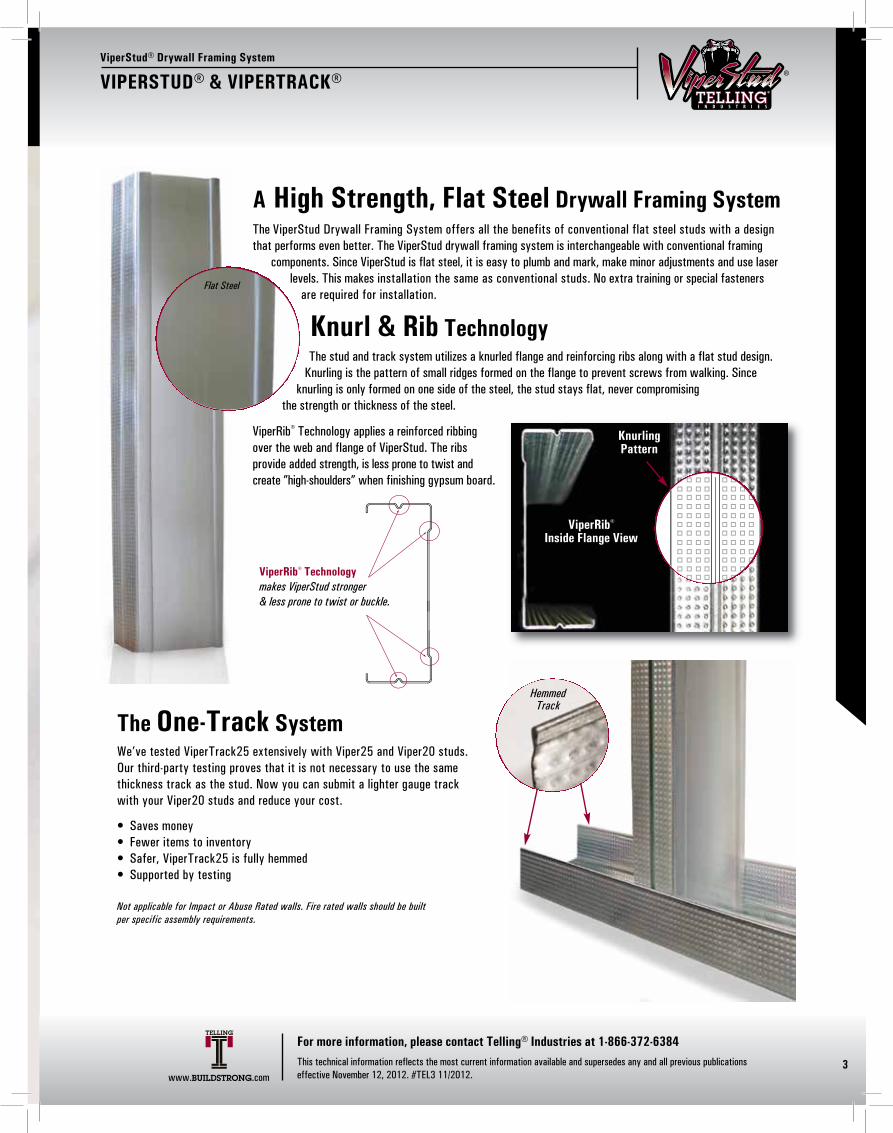
A High Strength, Flat Steel Drywall Framing SystemThe ViperStud Drywall Framing System offers all the benefits of conventional flat steel studs with a designthat performs even better. The ViperStud drywall framing system is interchangeable with conventional framing
components. Since ViperStud is flat steel, it is easy to plumb and mark, make minor adjustments and use laserlevels. This makes installation the same as conventional studs. No extra training or special fasteners
are required for installation.
Knurl & Rib TechnologyThe stud and track system utilizes a knurled flange and reinforcing ribs along with a flat stud design.
Knurling is the pattern of small ridges formed on the flange to prevent screws from walking. Since knurling is only formed on one side of the steel, the stud stays flat, never compromising
the strength or thickness of the steel.
ViperRib® Technology applies a reinforced ribbingover the web and flange of ViperStud. The ribs provide added strength, is less prone to twist and create ”high-shoulders” when finishing gypsum board.
ViperStud® Drywall Framing System
VIPERSTUD® & VIPERTRACK®
3
Knurling Pattern
Flat Steel
ViperRib®
Inside Flange View
ViperRib® Technologymakes ViperStud stronger & less prone to twist or buckle.
The One-Track SystemWe’ve tested ViperTrack25 extensively with Viper25 and Viper20 studs.Our third-party testing proves that it is not necessary to use the samethickness track as the stud. Now you can submit a lighter gauge trackwith your Viper20 studs and reduce your cost.
• Saves money• Fewer items to inventory• Safer, ViperTrack25 is fully hemmed• Supported by testing
Not applicable for Impact or Abuse Rated walls. Fire rated walls should be built per specific assembly requirements.
HemmedTrack
www.BUILDSTRONG.com
For more information, please contact Telling® Industries at 1-866-372-6384This technical information reflects the most current information available and supersedes any and all previous publications effective November 12, 2012. #TEL3 11/2012.
INTERIOR FRAMING
092005
Standing Strong.TM
The Proprietary Steel Framing System That Has Withstood The Test Of Time...
By providing a lighter, stronger,
more efficient framing system,
ViperStud® has earned the trust
of industry leaders nationwide.
Made from high-strength steel
and formed with exclusive
ViperRib technology,
ViperStud® is the flat steel
system that will be here
for the long term,
you can count on that.
A Track Record You Can Count On, Verified Code Compliant
IBC/IRC 2003, 2006, 2009, 2012 Compliant
PatentsViperStud Patent #D621,964 ViperTrack Patent #D621,963
The Viper25 & Viper20 values for composite limitingheights in this catalog have been submitted forrecognition in our ICC-ES ESR2620 & ATI ES CCRR-0154 reports. The updated physical properties of Viper-Stud in this catalog are greater than the minimumslisted in our evaluation reports. Please see the fullversions of these reports on www.BUILDSTRONG.com
U.S. Patent Nos. D621,964 and D621,963 are assigned to Ware Industries, Inc. and used by Telling Industries under license from Ware Industries, Inc.
"ViperStud®," "ViperTrack®," and "ViperRib®" are registered trademarks of Ware Industries, Inc. The ViperStud logo and "Standing Strong.™" are trademarks of Ware Industries, Inc. The "ViperStud®," "ViperTrack®,""ViperRib®," and "Standing Strong.™" trademarks are used by Telling Industries under license from Ware Industries, Inc.
© 2011 Ware Industries, Inc. All rights reserved.
ViperStud Drywall Framing System istested or conforms to these standards:• ASTM A1003 Standard Specification for Steel
Sheet, Carbon, Metallic- and Nonmetallic-Coated for Cold-Formed Framing Members
• ASTM C645 Standard Specification for NonstructuralSteel Framing Members
• ASTM C754 Standard Specification for Installation of Steel Framing Members to Receive Screw-AttachedGypsum Panel Products
• ASTM E90 Standard Test Method for Laboratory Measurement of Airborne Sound Transmission Loss of Building Partitions and Elements
• ASTM E119 Standard Test Methods for Fire Tests of Building construction and Materials. Fire rated for 1, 2, 3, and 4 hour rated walls.
• ASTM E72 Standard Test Methods of Conducting Strength Tests of Panels for Building Construction
• ASTM C1629 Standard Classification for Abuse- Resistant Nondecorated Interior Gypsum Panel Products and Fiber-Reinforced Cement Panels
ViperStud is listed in the following:• ATI CCRR-0154
• ICC-ES ESR #2620
• NYC Department of Buildings MEA 56-08-M, MEA 56-08-M Vol 2, MEA 235-08-M
Architectural Testing Approved & ICC ES Code CompliantViper25 & Viper20 manufactured by Telling® Industriesreceived an evaluation report (CCRR-0154) from ATI Evaluation Services and an evaluation report (ESR# 2620)from ICC Evaluation Service (ICC-ES), providing evidencethat the ViperStud Drywall Framing System meets coderequirements. Building officials, architects, contractors,specifiers, designers and others utilize these Evaluation Reports to provide a basis for using or approving metalframing in construction projects following the InternationalBuilding Code.
LEED® v3 InformationAvailable LEED® points in the following categories:• MR Credit 2 - Construction Waste Management
(1-2 points)• MR Credit 4 Recycled Content
(1-2 points)• MR Credit 5 - Regional Materials
(1-2 points)
Recycled Content • Total Recycled Content: 48%• Post Consumer Content: 32%• Pre Consumer (Post Industrial) Content: 16%
Code InformationViperStud Drywall Framing has been verified by thefollowing IAS Accredited Test Agencies and/or certifiedby the Product Evaluation Agencies listed here.
A High Strength, Flat Steel Drywall Framing SystemThe ViperStud Drywall Framing System offers all the benefits of conventional flat steel studs with a designthat performs even better. The ViperStud drywall framing system is interchangeable with conventional framing
components. Since ViperStud is flat steel, it is easy to plumb and mark, make minor adjustments and use laserlevels. This makes installation the same as conventional studs. No extra training or special fasteners
are required for installation.
Knurl & Rib TechnologyThe stud and track system utilizes a knurled flange and reinforcing ribs along with a flat stud design.
Knurling is the pattern of small ridges formed on the flange to prevent screws from walking. Since knurling is only formed on one side of the steel, the stud stays flat, never compromising
the strength or thickness of the steel.
ViperRib® Technology applies a reinforced ribbingover the web and flange of ViperStud. The ribs provide added strength, is less prone to twist and create ”high-shoulders” when finishing gypsum board.
ViperStud® Drywall Framing System
VIPERSTUD® & VIPERTRACK®
3
Knurling Pattern
Flat Steel
ViperRib®
Inside Flange View
ViperRib® Technologymakes ViperStud stronger & less prone to twist or buckle.
The One-Track SystemWe’ve tested ViperTrack25 extensively with Viper25 and Viper20 studs.Our third-party testing proves that it is not necessary to use the samethickness track as the stud. Now you can submit a lighter gauge trackwith your Viper20 studs and reduce your cost.
• Saves money• Fewer items to inventory• Safer, ViperTrack25 is fully hemmed• Supported by testing
Not applicable for Impact or Abuse Rated walls. Fire rated walls should be built per specific assembly requirements.
HemmedTrack
www.BUILDSTRONG.com
For more information, please contact Telling® Industries at 1-866-372-6384This technical information reflects the most current information available and supersedes any and all previous publications effective November 12, 2012. #TEL3 11/2012.

BUILDSTRONG
www.BUILDSTRONG.com6
MODEL NO.VIPERTRACK25
VIPERTRACK20
VIPERTRACK20
VIPERTRACK30mil
VIPERTRACK33mil
DESIGNTHICKNESS
(in)0.0155
0.0205
0.0220
0.0312
0.0346
MINIMUMTHICKNESS
(in)0.0147
0.0195
0.0209
0.0296
0.0329
YIELD(ksi)50
57
57
33
33
COATING 4,5
G40
G40
G40
G40
G40
WEB SIZES(in)
1-5/8, 2-1/2, 3-5/8, 4, 61-5/8, 2-1/2, 3-5/8
2-1/2, 3-5/82-1/2, 3-5/8
4, 64, 6 4, 6
1-5/8, 2-1/2, 3-5/8, 4, 62-1/2, 3-5/8, 4, 62-1/2, 3-5/8, 4, 6
1-5/8, 2-1/2, 3-5/8, 4, 62-1/2, 3-5/8, 4, 62-1/2, 3-5/8, 4, 6
RETURNLIP
1/41/41/41/41/4
12”12”
B. C.
ViperStud® Drywall Framing System
4
PHYSICAL PROPERTIES
Notes:1. Per ASTM C645 & ASTM A 1003, Table 12. G60 and G90 available upon request.3. Knockout size for 1-5/8” & 2-1/2” Stud is 3/4” x 2-1/2”. Knockout size for 3-5/8”, 4”, & 6” Stud is 1-1/2” x 2-1/2”
MODEL NO.VIPER25VIPER20VIPER20
VIPER 30milVIPER 33mil
DESIGNTHICKNESS
(in)0.01550.02050.02200.03120.0346
MINIMUMTHICKNESS
(in)0.01470.01950.02090.02960.0329
YIELD(ksi)5057573333
COATING 1, 2
G40G40G40G40G40
COATING 1, 2
G40G40G40G40G40
WEB SIZES(in)
1-5/8, 2-1/2, 3-5/8, 4, 61-5/8, 2-1/2, 3-5/8
4, 61-5/8, 2-1/2, 3-5/8, 4, 61-5/8, 2-1/2, 3-5/8, 4, 6
FLANGE(in)
1-1/41-1/41-1/41-1/41-1/4
MODEL NO.
VIPERTRACK25VIPERTRACK20VIPERTRACK20
VIPERTRACK 30milVIPERTRACK 33mil
DESIGNTHICKNESS
(in)
0.01550.02050.02200.03120.0346
MINIMUMTHICKNESS
(in)
0.01470.01950.02090.02960.0329
YIELD(ksi)
5050503333
WEB SIZES(in)
1-5/8, 2-1/2, 3-5/8, 4, 61-5/8, 2-1/2, 3-5/8
4, 61-5/8, 2-1/2, 3-5/8, 4, 61-5/8, 2-1/2, 3-5/8, 4, 6
FLANGE(in)
1-1/41-1/41-1/41-1/41-1/4
ViperStud®
ViperTrack®
DEEP LEG DEFLECTION TRACKDeflection track can be required at the top of a wall to allow for anticipateddownward movement of the primary structure. A gap is provided between theend of the stud and track to accommodatethis movement. The studs are not fastenedto the track to allow movement up ordown. The bridging is required within 12”from the top to keep the stud in place and provide rotational restraint. The leg of the track must be long enough to provide the required gap, bearing surfacefor the studs and allow for constructiontolerances.
LEG SIZE GAP LOAD MAX HEIGHT(in) (in) (lb.) 5 psf, 16” o.c.2” 1/2” 34 10’-4”2” 1/2” 60 20’-6”
2-1/2” 3/4” 40 13’-8”3” 1” 30 10’-3”2” 1/2” 69 23’-8”
2-1/2” 3/4” 46 15’-9”3” 1” 35 11’-10”2” 1/2” 92 27’-6”
2-1/2” 3/4” 61 18’-4”3” 1” 46 13’-9”2” 1/2” 113 33’-10”
2-1/2” 3/4” 75 22’-7”3” 1” 56 16’-11”Studs are secured by one
of the following methods:
A. CR channel and BRC Clip. 12” down from the stud end.
B. Attaching flat strap at each side of the stud flange. 12” down from the stud end.
C. Attaching 2 screws at each leg of the deep leg track, near the stud flanges. (Total 4 screws)
A.
Notes:1. Max wall height based on stud spacing of 16” o.c. & 5 PSF lateral load2. 1-5/8” deep leg track available with max 2” leg3. Wall studs are not fastened to deep leg track. 4. G60, G90 available upon request.5. Per ASTM C 645 & ASTM A 1003, Table 1
www.BUILDSTRONG.com
For more information, please contact Telling® Industries at 1-866-372-6384This technical information reflects the most current information available and supersedes any and all previous publications effective November 12, 2012. #TEL3 11/2012.
VIPERTRACK 1.25” LEG162VT125-15 1.25 0.22 0.0155 0.0147 50 0.064 0.035 0.040 0.736 0.011 0.0125 0.412 0.022 0.018 0.53 -0.877 0.0051 0.006 1.22 0.480250VT125-15 1.25 0.26 0.0155 0.0147 50 0.078 0.086 0.066 1.050 0.012 0.0133 0.400 0.054 0.027 0.80 -0.768 0.0062 0.015 1.36 0.683362VT125-155 1.25 0.32 0.0155 0.0147 50 0.095 0.197 0.105 1.440 0.014 0.0139 0.381 0.115 0.039 1.15 -0.665 0.0076 0.035 1.63 0.833400VT125-155 1.25 0.34 0.0155 0.0147 50 0.101 0.247 0.120 1.560 0.014 0.0141 0.374 0.141 0.043 1.27 -0.638 0.0081 0.043 1.73 0.864600VT125-156 1.25 0.45 0.0155 0.0147 50 0.132 0.642 0.210 2.210 0.015 0.0146 0.342 0.325 0.063 1.90 -0.523 0.0106 0.109 2.29 0.948162VT125-20 1.25 0.29 0.0205 0.0195 50 0.085 0.046 0.052 0.737 0.014 0.0165 0.411 0.031 0.027 0.79 -0.874 0.0119 0.008 1.22 0.483250VT125-20 1.25 0.35 0.0205 0.0195 50 0.103 0.114 0.087 1.060 0.016 0.0175 0.399 0.081 0.045 1.33 -0.766 0.0144 0.020 1.36 0.685362VT125-20 1.25 0.43 0.0205 0.0195 50 0.126 0.261 0.139 1.440 0.018 0.0183 0.380 0.179 0.064 1.92 -0.663 0.0176 0.046 1.63 0.835400VT125-21 1.25 0.49 0.0220 0.0209 50 0.143 0.351 0.170 1.570 0.020 0.0199 0.373 0.246 0.081 2.41 -0.635 0.0231 0.061 1.73 0.865600VT125-216 1.25 0.64 0.0220 0.0209 50 0.187 0.910 0.297 2.210 0.022 0.0206 0.341 0.557 0.117 3.49 -0.520 0.0302 0.154 2.29 0.949162VT125-30 1.25 0.44 0.0312 0.0296 33 0.129 0.071 0.080 0.741 0.022 0.0249 0.409 0.056 0.051 1.00 -0.868 0.0419 0.012 1.21 0.488250VT125-30 1.25 0.53 0.0312 0.0296 33 0.156 0.175 0.132 1.060 0.025 0.0265 0.397 0.142 0.090 1.77 -0.760 0.0508 0.030 1.36 0.689362VT125-30 1.25 0.65 0.0312 0.0296 33 0.192 0.399 0.211 1.440 0.027 0.0277 0.378 0.331 0.152 3.00 -0.658 0.0621 0.069 1.63 0.837400VT125-30 1.25 0.69 0.0312 0.0296 33 0.203 0.499 0.240 1.570 0.028 0.0280 0.371 0.417 0.176 3.47 -0.631 0.0659 0.086 1.73 0.867600VT125-30 1.25 0.90 0.0312 0.0296 33 0.266 1.300 0.421 2.210 0.031 0.0290 0.339 1.030 0.250 4.94 -0.517 0.0862 0.216 2.29 0.949162VT125-33 1.25 0.49 0.0346 0.0329 33 0.143 0.079 0.088 0.742 0.024 0.0276 0.408 0.064 0.059 1.16 -0.866 0.0571 0.013 1.21 0.489250VT125-33 1.25 0.59 0.0346 0.0329 33 0.174 0.195 0.146 1.060 0.027 0.0293 0.396 0.162 0.103 2.04 -0.758 0.0692 0.033 1.36 0.690362VT125-33 1.25 0.72 0.0346 0.0329 33 0.212 0.443 0.234 1.440 0.030 0.0306 0.377 0.375 0.173 3.43 -0.657 0.0848 0.077 1.63 0.838400VT125-33 1.25 0.77 0.0346 0.0329 33 0.225 0.554 0.266 1.570 0.031 0.0309 0.370 0.473 0.200 3.95 -0.629 0.0899 0.096 1.73 0.868600VT125-33 1.25 1.00 0.0346 0.0329 33 0.295 1.440 0.467 2.210 0.034 0.0321 0.339 1.190 0.298 5.89 -0.516 0.1180 0.239 2.29 0.949
Nominal Moment for
ConventionalStuds2
Mn(in-k)
DistortionalBucklingNominal
Moment1,3
Viper
Mnd(in-k)
ViperStud® Drywall Framing System
5
MEMBERDESIGN
(in)MIN(in)
YIELD(ksi)
WEIGHT(lb/ft)
AREA(in1)
Ix(in3)
rx(in)
Iy(in3)
ry(in)
Ixd(in3)
Sx(in2)
AllowableMoment
Ma(in-k)
CriticalUnbracedLength6
Lu(in)
GROSS PROPERTIES
EFFECTIVEPROPERTIES
MOMENTS
Notes:1. Viper25 and Viper20 nominal moments are based on testing. Allowable moment (Ma) is calculated with safety factor of 1.81 in accordance with chapter F of AISI S100-07 specification. 2. Nominal moment for Viper 30mil, Viper 33mil and conventional studs are based on calculations per AISI S100-07. Allowable moments (Ma) can be calculated with a 1.67 safety factor. 3. Section properties are in accordance with AISI S100-07. Viper25 and Viper20 section properties are based on testing.4. Web depth-to-thickness ratio exceeds 200. 5. Web depth-to-thickness ratio exceeds 260. 6. ViperStud is considered fully braced when the unbraced length is less than listed Lu.7. ΚΦ assumed to be zero for distortional buckling moments.
Local BucklingNominal
Moment1,3
Viper
Mnl(in-k)
Notes:1. See page 6 for ViperTrack notes.
MEMBERDESIGN
(in)
LEGSIZE(in)
WEIGHT(lb/ft)
AREA(in2)
Ix(in4)
Sx(in3)
rx(in)
Iy(in4)
Sy(in3)
ry(in)
Ixd(in4)
Sxe(in3)
Ma(in-k)
Xo(in)
Jx103
(in4)Cw(in6)
ro(in)
β
GROSS PROPERTIES
EFFECTIVE PROPERTIES
TORSIONAL PROPERTIES
MIN(in)
YIELD(ksi)
VIPERSTUD®
VIPERTRACK®
SECTION PROPERTIES
MODELNO. GAUGE
25EQ
20EQ
20DW
20STR
VIPER25
VIPER20
VIPER30mil
VIPER33mil
162VS125-15 0.0155 0.0147 50 0.24 0.071 0.032 0.671 0.015 0.461 0.032 0.024 0.66 1.42 1.20 1.02 (18 mil) 25.1250VS125-15 0.0155 0.0147 50 0.29 0.085 0.084 0.998 0.017 0.452 0.090 0.042 1.17 2.72 2.12 1.72 (18 mil) 24.8362VS125-154 0.0155 0.0147 50 0.35 0.102 0.199 1.390 0.019 0.435 0.205 0.058 1.60 3.48 2.90 2.47 (18 mil) 24.5400VS125-154 0.0155 0.0147 50 0.37 0.108 0.250 1.520 0.020 0.429 0.255 0.061 1.69 3.99 3.06 2.74 (18 mil) 24.4600VS125-155 0.0155 0.0147 50 0.47 0.139 0.659 2.180 0.022 0.397 0.628 0.085 2.36 5.90 4.27 4.13 (18 mil) 23.7162VS125-20 0.0205 0.0195 57 0.32 0.093 0.042 0.673 0.020 0.459 0.050 0.038 1.18 2.74 2.14 1.99 (30 mil) 23.4250VS125-20 0.0205 0.0195 57 0.38 0.111 0.111 1.000 0.023 0.451 0.129 0.065 2.05 4.50 3.71 3.49 (30 mil) 23.1362VS125-20 0.0205 0.0195 57 0.45 0.134 0.261 1.400 0.025 0.433 0.298 0.090 2.85 6.10 5.15 5.14 (30 mil) 22.8400VS125-21 0.0220 0.0209 57 0.52 0.152 0.352 1.520 0.028 0.426 0.377 0.117 3.69 8.02 6.67 5.74 (30 mil) 22.7600VS125-215 0.0220 0.0209 57 0.67 0.196 0.929 2.180 0.030 0.394 0.869 0.161 5.06 11.20 9.16 9.00 (30 mil) 22.0162VS125-30 0.0312 0.0296 33 0.46 0.135 0.062 0.680 0.028 0.455 0.062 0.067 1.32 2.21 2.38 1.99 (30 mil) 30.8250VS125-30 0.0312 0.0296 33 0.55 0.161 0.166 1.020 0.032 0.448 0.163 0.120 2.31 3.96 3.86 3.49 (30 mil) 30.1362VS125-30 0.0312 0.0296 33 0.67 0.197 0.391 1.410 0.037 0.431 0.385 0.172 3.39 5.67 5.85 5.14 (30 mil) 29.7400VS125-30 0.0312 0.0296 33 0.71 0.209 0.493 1.540 0.038 0.425 0.486 0.191 3.78 6.31 6.52 5.74 (30 mil) 29.6600VS125-30 0.0312 0.0296 33 0.29 0.271 1.310 2.190 0.042 0.392 1.230 0.341 5.95 11.30 9.93 9.00 (30 mil) 28.7162VS125-33 0.0346 0.0329 33 0.50 0.147 0.069 0.683 0.030 0.453 0.068 0.077 1.53 2.55 2.71 2.29 (33 mil) 30.8250VS125-33 0.0346 0.0329 33 0.61 0.178 0.183 1.010 0.036 0.447 0.181 0.137 2.65 4.53 4.42 4.02 (33 mil) 30.1362VS125-33 0.0346 0.0329 33 0.75 0.220 0.432 1.400 0.040 0.429 0.428 0.201 3.96 6.62 6.75 6.00 (33 mil) 29.7400VS125-33 0.0346 0.0329 33 0.78 0.230 0.544 1.540 0.041 0.424 0.539 0.224 4.42 7.38 7.53 6.70 (33 mil) 29.5600VS125-33 0.0346 0.0329 33 0.02 0.301 1.440 2.190 0.046 0.391 1.390 0.400 6.93 13.20 11.60 10.55 (33 mil) 28.6
www.BUILDSTRONG.com
For more information, please contact Telling® Industries at 1-866-372-6384This technical information reflects the most current information available and supersedes any and all previous publications effective November 12, 2012. #TEL3 11/2012.

INTERIOR FRAMING
092007
MODEL NO.VIPERTRACK25
VIPERTRACK20
VIPERTRACK20
VIPERTRACK30mil
VIPERTRACK33mil
DESIGNTHICKNESS
(in)0.0155
0.0205
0.0220
0.0312
0.0346
MINIMUMTHICKNESS
(in)0.0147
0.0195
0.0209
0.0296
0.0329
YIELD(ksi)50
57
57
33
33
COATING 4,5
G40
G40
G40
G40
G40
WEB SIZES(in)
1-5/8, 2-1/2, 3-5/8, 4, 61-5/8, 2-1/2, 3-5/8
2-1/2, 3-5/82-1/2, 3-5/8
4, 64, 6 4, 6
1-5/8, 2-1/2, 3-5/8, 4, 62-1/2, 3-5/8, 4, 62-1/2, 3-5/8, 4, 6
1-5/8, 2-1/2, 3-5/8, 4, 62-1/2, 3-5/8, 4, 62-1/2, 3-5/8, 4, 6
RETURNLIP
1/41/41/41/41/4
12”12”
B. C.
ViperStud® Drywall Framing System
4
PHYSICAL PROPERTIES
Notes:1. Per ASTM C645 & ASTM A 1003, Table 12. G60 and G90 available upon request.3. Knockout size for 1-5/8” & 2-1/2” Stud is 3/4” x 2-1/2”. Knockout size for 3-5/8”, 4”, & 6” Stud is 1-1/2” x 2-1/2”
MODEL NO.VIPER25VIPER20VIPER20
VIPER 30milVIPER 33mil
DESIGNTHICKNESS
(in)0.01550.02050.02200.03120.0346
MINIMUMTHICKNESS
(in)0.01470.01950.02090.02960.0329
YIELD(ksi)5057573333
COATING 1, 2
G40G40G40G40G40
COATING 1, 2
G40G40G40G40G40
WEB SIZES(in)
1-5/8, 2-1/2, 3-5/8, 4, 61-5/8, 2-1/2, 3-5/8
4, 61-5/8, 2-1/2, 3-5/8, 4, 61-5/8, 2-1/2, 3-5/8, 4, 6
FLANGE(in)
1-1/41-1/41-1/41-1/41-1/4
MODEL NO.
VIPERTRACK25VIPERTRACK20VIPERTRACK20
VIPERTRACK 30milVIPERTRACK 33mil
DESIGNTHICKNESS
(in)
0.01550.02050.02200.03120.0346
MINIMUMTHICKNESS
(in)
0.01470.01950.02090.02960.0329
YIELD(ksi)
5050503333
WEB SIZES(in)
1-5/8, 2-1/2, 3-5/8, 4, 61-5/8, 2-1/2, 3-5/8
4, 61-5/8, 2-1/2, 3-5/8, 4, 61-5/8, 2-1/2, 3-5/8, 4, 6
FLANGE(in)
1-1/41-1/41-1/41-1/41-1/4
ViperStud®
ViperTrack®
DEEP LEG DEFLECTION TRACKDeflection track can be required at the top of a wall to allow for anticipateddownward movement of the primary structure. A gap is provided between theend of the stud and track to accommodatethis movement. The studs are not fastenedto the track to allow movement up ordown. The bridging is required within 12”from the top to keep the stud in place and provide rotational restraint. The leg of the track must be long enough to provide the required gap, bearing surfacefor the studs and allow for constructiontolerances.
LEG SIZE GAP LOAD MAX HEIGHT(in) (in) (lb.) 5 psf, 16” o.c.2” 1/2” 34 10’-4”2” 1/2” 60 20’-6”
2-1/2” 3/4” 40 13’-8”3” 1” 30 10’-3”2” 1/2” 69 23’-8”
2-1/2” 3/4” 46 15’-9”3” 1” 35 11’-10”2” 1/2” 92 27’-6”
2-1/2” 3/4” 61 18’-4”3” 1” 46 13’-9”2” 1/2” 113 33’-10”
2-1/2” 3/4” 75 22’-7”3” 1” 56 16’-11”Studs are secured by one
of the following methods:
A. CR channel and BRC Clip. 12” down from the stud end.
B. Attaching flat strap at each side of the stud flange. 12” down from the stud end.
C. Attaching 2 screws at each leg of the deep leg track, near the stud flanges. (Total 4 screws)
A.
Notes:1. Max wall height based on stud spacing of 16” o.c. & 5 PSF lateral load2. 1-5/8” deep leg track available with max 2” leg3. Wall studs are not fastened to deep leg track. 4. G60, G90 available upon request.5. Per ASTM C 645 & ASTM A 1003, Table 1
www.BUILDSTRONG.com
For more information, please contact Telling® Industries at 1-866-372-6384This technical information reflects the most current information available and supersedes any and all previous publications effective November 12, 2012. #TEL3 11/2012.
VIPERTRACK 1.25” LEG162VT125-15 1.25 0.22 0.0155 0.0147 50 0.064 0.035 0.040 0.736 0.011 0.0125 0.412 0.022 0.018 0.53 -0.877 0.0051 0.006 1.22 0.480250VT125-15 1.25 0.26 0.0155 0.0147 50 0.078 0.086 0.066 1.050 0.012 0.0133 0.400 0.054 0.027 0.80 -0.768 0.0062 0.015 1.36 0.683362VT125-155 1.25 0.32 0.0155 0.0147 50 0.095 0.197 0.105 1.440 0.014 0.0139 0.381 0.115 0.039 1.15 -0.665 0.0076 0.035 1.63 0.833400VT125-155 1.25 0.34 0.0155 0.0147 50 0.101 0.247 0.120 1.560 0.014 0.0141 0.374 0.141 0.043 1.27 -0.638 0.0081 0.043 1.73 0.864600VT125-156 1.25 0.45 0.0155 0.0147 50 0.132 0.642 0.210 2.210 0.015 0.0146 0.342 0.325 0.063 1.90 -0.523 0.0106 0.109 2.29 0.948162VT125-20 1.25 0.29 0.0205 0.0195 50 0.085 0.046 0.052 0.737 0.014 0.0165 0.411 0.031 0.027 0.79 -0.874 0.0119 0.008 1.22 0.483250VT125-20 1.25 0.35 0.0205 0.0195 50 0.103 0.114 0.087 1.060 0.016 0.0175 0.399 0.081 0.045 1.33 -0.766 0.0144 0.020 1.36 0.685362VT125-20 1.25 0.43 0.0205 0.0195 50 0.126 0.261 0.139 1.440 0.018 0.0183 0.380 0.179 0.064 1.92 -0.663 0.0176 0.046 1.63 0.835400VT125-21 1.25 0.49 0.0220 0.0209 50 0.143 0.351 0.170 1.570 0.020 0.0199 0.373 0.246 0.081 2.41 -0.635 0.0231 0.061 1.73 0.865600VT125-216 1.25 0.64 0.0220 0.0209 50 0.187 0.910 0.297 2.210 0.022 0.0206 0.341 0.557 0.117 3.49 -0.520 0.0302 0.154 2.29 0.949162VT125-30 1.25 0.44 0.0312 0.0296 33 0.129 0.071 0.080 0.741 0.022 0.0249 0.409 0.056 0.051 1.00 -0.868 0.0419 0.012 1.21 0.488250VT125-30 1.25 0.53 0.0312 0.0296 33 0.156 0.175 0.132 1.060 0.025 0.0265 0.397 0.142 0.090 1.77 -0.760 0.0508 0.030 1.36 0.689362VT125-30 1.25 0.65 0.0312 0.0296 33 0.192 0.399 0.211 1.440 0.027 0.0277 0.378 0.331 0.152 3.00 -0.658 0.0621 0.069 1.63 0.837400VT125-30 1.25 0.69 0.0312 0.0296 33 0.203 0.499 0.240 1.570 0.028 0.0280 0.371 0.417 0.176 3.47 -0.631 0.0659 0.086 1.73 0.867600VT125-30 1.25 0.90 0.0312 0.0296 33 0.266 1.300 0.421 2.210 0.031 0.0290 0.339 1.030 0.250 4.94 -0.517 0.0862 0.216 2.29 0.949162VT125-33 1.25 0.49 0.0346 0.0329 33 0.143 0.079 0.088 0.742 0.024 0.0276 0.408 0.064 0.059 1.16 -0.866 0.0571 0.013 1.21 0.489250VT125-33 1.25 0.59 0.0346 0.0329 33 0.174 0.195 0.146 1.060 0.027 0.0293 0.396 0.162 0.103 2.04 -0.758 0.0692 0.033 1.36 0.690362VT125-33 1.25 0.72 0.0346 0.0329 33 0.212 0.443 0.234 1.440 0.030 0.0306 0.377 0.375 0.173 3.43 -0.657 0.0848 0.077 1.63 0.838400VT125-33 1.25 0.77 0.0346 0.0329 33 0.225 0.554 0.266 1.570 0.031 0.0309 0.370 0.473 0.200 3.95 -0.629 0.0899 0.096 1.73 0.868600VT125-33 1.25 1.00 0.0346 0.0329 33 0.295 1.440 0.467 2.210 0.034 0.0321 0.339 1.190 0.298 5.89 -0.516 0.1180 0.239 2.29 0.949
Nominal Moment for
ConventionalStuds2
Mn(in-k)
DistortionalBucklingNominal
Moment1,3
Viper
Mnd(in-k)
ViperStud® Drywall Framing System
5
MEMBERDESIGN
(in)MIN(in)
YIELD(ksi)
WEIGHT(lb/ft)
AREA(in1)
Ix(in3)
rx(in)
Iy(in3)
ry(in)
Ixd(in3)
Sx(in2)
AllowableMoment
Ma(in-k)
CriticalUnbracedLength6
Lu(in)
GROSS PROPERTIES
EFFECTIVEPROPERTIES
MOMENTS
Notes:1. Viper25 and Viper20 nominal moments are based on testing. Allowable moment (Ma) is calculated with safety factor of 1.81 in accordance with chapter F of AISI S100-07 specification. 2. Nominal moment for Viper 30mil, Viper 33mil and conventional studs are based on calculations per AISI S100-07. Allowable moments (Ma) can be calculated with a 1.67 safety factor. 3. Section properties are in accordance with AISI S100-07. Viper25 and Viper20 section properties are based on testing.4. Web depth-to-thickness ratio exceeds 200. 5. Web depth-to-thickness ratio exceeds 260. 6. ViperStud is considered fully braced when the unbraced length is less than listed Lu.7. ΚΦ assumed to be zero for distortional buckling moments.
Local BucklingNominal
Moment1,3
Viper
Mnl(in-k)
Notes:1. See page 6 for ViperTrack notes.
MEMBERDESIGN
(in)
LEGSIZE(in)
WEIGHT(lb/ft)
AREA(in2)
Ix(in4)
Sx(in3)
rx(in)
Iy(in4)
Sy(in3)
ry(in)
Ixd(in4)
Sxe(in3)
Ma(in-k)
Xo(in)
Jx103
(in4)Cw(in6)
ro(in)
β
GROSS PROPERTIES
EFFECTIVE PROPERTIES
TORSIONAL PROPERTIES
MIN(in)
YIELD(ksi)
VIPERSTUD®
VIPERTRACK®
SECTION PROPERTIES
MODELNO. GAUGE
25EQ
20EQ
20DW
20STR
VIPER25
VIPER20
VIPER30mil
VIPER33mil
162VS125-15 0.0155 0.0147 50 0.24 0.071 0.032 0.671 0.015 0.461 0.032 0.024 0.66 1.42 1.20 1.02 (18 mil) 25.1250VS125-15 0.0155 0.0147 50 0.29 0.085 0.084 0.998 0.017 0.452 0.090 0.042 1.17 2.72 2.12 1.72 (18 mil) 24.8362VS125-154 0.0155 0.0147 50 0.35 0.102 0.199 1.390 0.019 0.435 0.205 0.058 1.60 3.48 2.90 2.47 (18 mil) 24.5400VS125-154 0.0155 0.0147 50 0.37 0.108 0.250 1.520 0.020 0.429 0.255 0.061 1.69 3.99 3.06 2.74 (18 mil) 24.4600VS125-155 0.0155 0.0147 50 0.47 0.139 0.659 2.180 0.022 0.397 0.628 0.085 2.36 5.90 4.27 4.13 (18 mil) 23.7162VS125-20 0.0205 0.0195 57 0.32 0.093 0.042 0.673 0.020 0.459 0.050 0.038 1.18 2.74 2.14 1.99 (30 mil) 23.4250VS125-20 0.0205 0.0195 57 0.38 0.111 0.111 1.000 0.023 0.451 0.129 0.065 2.05 4.50 3.71 3.49 (30 mil) 23.1362VS125-20 0.0205 0.0195 57 0.45 0.134 0.261 1.400 0.025 0.433 0.298 0.090 2.85 6.10 5.15 5.14 (30 mil) 22.8400VS125-21 0.0220 0.0209 57 0.52 0.152 0.352 1.520 0.028 0.426 0.377 0.117 3.69 8.02 6.67 5.74 (30 mil) 22.7600VS125-215 0.0220 0.0209 57 0.67 0.196 0.929 2.180 0.030 0.394 0.869 0.161 5.06 11.20 9.16 9.00 (30 mil) 22.0162VS125-30 0.0312 0.0296 33 0.46 0.135 0.062 0.680 0.028 0.455 0.062 0.067 1.32 2.21 2.38 1.99 (30 mil) 30.8250VS125-30 0.0312 0.0296 33 0.55 0.161 0.166 1.020 0.032 0.448 0.163 0.120 2.31 3.96 3.86 3.49 (30 mil) 30.1362VS125-30 0.0312 0.0296 33 0.67 0.197 0.391 1.410 0.037 0.431 0.385 0.172 3.39 5.67 5.85 5.14 (30 mil) 29.7400VS125-30 0.0312 0.0296 33 0.71 0.209 0.493 1.540 0.038 0.425 0.486 0.191 3.78 6.31 6.52 5.74 (30 mil) 29.6600VS125-30 0.0312 0.0296 33 0.29 0.271 1.310 2.190 0.042 0.392 1.230 0.341 5.95 11.30 9.93 9.00 (30 mil) 28.7162VS125-33 0.0346 0.0329 33 0.50 0.147 0.069 0.683 0.030 0.453 0.068 0.077 1.53 2.55 2.71 2.29 (33 mil) 30.8250VS125-33 0.0346 0.0329 33 0.61 0.178 0.183 1.010 0.036 0.447 0.181 0.137 2.65 4.53 4.42 4.02 (33 mil) 30.1362VS125-33 0.0346 0.0329 33 0.75 0.220 0.432 1.400 0.040 0.429 0.428 0.201 3.96 6.62 6.75 6.00 (33 mil) 29.7400VS125-33 0.0346 0.0329 33 0.78 0.230 0.544 1.540 0.041 0.424 0.539 0.224 4.42 7.38 7.53 6.70 (33 mil) 29.5600VS125-33 0.0346 0.0329 33 0.02 0.301 1.440 2.190 0.046 0.391 1.390 0.400 6.93 13.20 11.60 10.55 (33 mil) 28.6
www.BUILDSTRONG.com
For more information, please contact Telling® Industries at 1-866-372-6384This technical information reflects the most current information available and supersedes any and all previous publications effective November 12, 2012. #TEL3 11/2012.

BUILDSTRONG
www.BUILDSTRONG.com8
VIPERTRACK 2.00” LEG162VT200-15 2.00 0.30 0.0155 0.0147 50 0.087 0.052 0.060 0.773 0.038 0.030 0.663 0.025 0.017 0.50 -1.57 0.00700 0.0212 1.87 0.295250VT200-15 2.00 0.34 0.0155 0.0147 50 0.101 0.126 0.096 1.117 0.044 0.032 0.662 0.060 0.026 0.79 -1.43 0.00808 0.0535 1.93 0.453362VT200-155 2.00 0.40 0.0155 0.0147 50 0.118 0.278 0.148 1.533 0.050 0.034 0.648 0.127 0.039 1.16 -1.28 0.00948 0.122 2.10 0.629400VT200-155 2.00 0.42 0.0155 0.0147 50 0.124 0.345 0.167 1.667 0.051 0.034 0.642 0.155 0.043 1.28 -1.24 0.00995 0.152 2.17 0.676600VT200-156 2.00 0.53 0.0155 0.0147 50 0.155 0.859 0.281 2.353 0.057 0.036 0.608 0.357 0.065 1.93 -1.06 0.0124 0.384 2.65 0.841162VT200-20 2.00 0.39 0.0205 0.0195 57 0.116 0.069 0.079 0.775 0.051 0.039 0.662 0.036 0.027 0.91 -1.57 0.0162 0.028 1.87 0.296250VT200-20 2.00 0.45 0.0205 0.0195 57 0.134 0.167 0.127 1.118 0.058 0.042 0.661 0.091 0.041 1.41 -1.42 0.0187 0.071 1.93 0.454362VT200-20 2.00 0.53 0.0205 0.0195 57 0.157 0.369 0.196 1.534 0.066 0.045 0.647 0.190 0.060 2.06 -1.28 0.0219 0.161 2.10 0.630400VT200-21 2.00 0.60 0.0220 0.0209 57 0.176 0.491 0.237 1.670 0.072 0.048 0.641 0.261 0.076 2.59 -1.23 0.0284 0.216 2.17 0.677600VT200-216 2.00 0.75 0.0220 0.0209 57 0.220 1.221 0.398 2.350 0.081 0.051 0.606 0.602 0.115 3.91 -1.05 0.0355 0.544 2.65 0.842162VT200-30 2.00 0.60 0.0312 0.0296 33 0.176 0.107 0.120 0.779 0.077 0.596 0.660 0.069 0.055 1.09 -1.56 0.0571 0.0431 1.87 0.299250VT200-30 2.00 0.69 0.0312 0.0296 33 0.203 0.256 0.193 1.120 0.088 0.064 0.659 0.174 0.098 1.94 -1.42 0.0659 0.108 1.92 0.457362VT200-30 2.00 0.81 0.0312 0.0296 33 0.238 0.563 0.298 1.540 0.099 0.675 0.645 0.400 0.167 3.29 -1.27 0.0773 0.246 2.10 0.633400VT200-30 2.00 0.85 0.0312 0.0296 33 0.250 0.698 0.336 1.670 0.102 0.068 0.639 0.502 0.188 3.71 -1.23 0.0811 0.306 2.17 0.680600VT200-30 2.00 1.06 0.0312 0.0296 33 0.312 1.735 0.564 2.360 0.114 0.072 0.605 1.270 0.276 5.45 -1.05 0.1010 0.769 2.65 0.843162VT200-33 2.00 0.66 0.0346 0.0329 33 0.195 0.119 0.133 0.780 0.085 0.066 0.660 0.080 0.064 1.27 -1.56 0.0779 0.048 1.87 0.300250VT200-33 2.00 0.77 0.0346 0.0329 33 0.225 0.284 0.214 1.120 0.098 0.071 0.658 0.199 0.113 2.23 -1.42 0.0899 0.120 1.92 0.458362VT200-33 2.00 0.90 0.0346 0.0329 33 0.264 0.626 0.330 1.540 0.110 0.075 0.644 0.455 0.191 3.76 -1.27 0.1050 0.272 2.10 0.634400VT200-33 2.00 0.94 0.0346 0.0329 33 0.277 0.775 0.373 1.670 0.113 0.076 0.638 0.570 0.220 4.34 -1.23 0.1110 0.340 2.17 0.680600VT200-33 2.00 1.18 0.0346 0.0329 33 0.347 1.930 0.625 2.360 0.126 0.080 0.604 1.480 0.338 6.69 -1.05 0.1380 0.852 2.65 0.844VIPERTRACK 2.50” LEG162VT250-20 2.50 0.46 0.0205 0.0195 57 0.136 0.085 0.097 0.790 0.092 0.059 0.823 0.039 0.026 0.88 -2.05 0.0191 0.052 2.35 0.237250VT250-20 2.50 0.52 0.0205 0.0195 57 0.154 0.202 0.153 1.150 0.106 0.064 0.830 0.094 0.041 1.40 -1.89 0.0216 0.130 2.36 0.360362VT250-20 2.50 0.60 0.0205 0.0195 57 0.177 0.440 0.234 1.580 0.120 0.068 0.822 0.200 0.060 2.06 -1.71 0.0248 0.295 2.47 0.519400VT250-21 2.50 0.68 0.0220 0.0209 57 0.198 0.584 0.282 1.720 0.132 0.074 0.817 0.274 0.076 2.58 -1.66 0.0320 0.395 2.53 0.566600VT250-216 2.50 0.82 0.0220 0.0209 57 0.242 1.430 0.465 2.430 0.150 0.078 0.785 0.630 0.115 3.92 -1.45 0.0391 0.989 2.93 0.757162VT250-30 2.50 0.71 0.0312 0.0296 33 0.207 0.131 0.147 0.794 0.140 0.090 0.822 0.076 0.057 1.13 -2.04 0.0672 0.080 2.34 0.239250VT250-30 2.50 0.80 0.0312 0.0296 33 0.234 0.310 0.233 1.150 0.161 0.097 0.828 0.190 0.102 2.01 -1.88 0.0761 0.199 2.35 0.363362VT250-30 2.50 0.92 0.0312 0.0296 33 0.270 0.673 0.356 1.580 0.181 0.102 0.820 0.437 0.167 3.30 -1.71 0.0875 0.449 2.47 0.521400VT250-30 2.50 0.96 0.0312 0.0296 33 0.281 0.831 0.400 1.720 0.187 0.104 0.816 0.548 0.185 3.66 -1.66 0.0913 0.560 2.52 0.568600VT250-30 2.50 1.17 0.0312 0.0296 33 0.344 2.030 0.659 2.430 0.211 0.110 0.784 1.330 0.275 5.43 -1.44 0.1120 1.400 2.93 0.758162VT250-33 2.50 0.78 0.0346 0.0329 33 0.230 0.145 0.163 0.796 0.155 0.100 0.821 0.088 0.066 1.31 -2.04 0.0917 0.089 2.34 0.239250VT250-33 2.50 0.89 0.0346 0.0329 33 0.260 0.344 0.258 1.150 0.178 0.107 0.827 0.218 0.117 2.32 -1.88 0.1040 0.221 2.35 0.363362VT250-33 2.50 1.02 0.0346 0.0329 33 0.299 0.748 0.395 1.580 0.201 0.114 0.820 0.498 0.198 3.92 -1.71 0.1190 0.498 2.47 0.522400VT250-33 2.50 1.06 0.0346 0.0329 33 0.312 0.923 0.443 1.720 0.207 0.115 0.815 0.623 0.226 4.46 -1.66 0.1240 0.621 2.52 0.569600VT250-33 2.50 1.30 0.0346 0.0329 33 0.381 2.250 0.730 2.430 0.234 0.122 0.783 1.580 0.336 6.64 -1.44 0.1520 1.550 2.93 0.759VIPERTRACK 3.00” LEG162VT300-20 3.00 0.53 0.0205 0.0195 57 0.157 0.100 0.114 0.801 0.151 0.083 0.981 0.041 0.028 0.95 -2.53 0.0219 0.087 2.83 0.200250VT300-20 3.00 0.59 0.0205 0.0195 57 0.175 0.237 0.180 1.170 0.173 0.089 0.995 0.098 0.041 1.39 -2.36 0.0245 0.216 2.81 0.298362VT300-20 3.00 0.67 0.0205 0.0195 57 0.198 0.512 0.272 1.610 0.195 0.095 0.994 0.207 0.060 2.05 -2.17 0.0277 0.484 2.87 0.433400VT300-21 3.00 0.75 0.0220 0.0209 57 0.220 0.677 0.327 1.750 0.216 0.103 0.991 0.284 0.076 2.58 -2.11 0.0355 0.647 2.92 0.477600VT300-216 3.00 0.90 0.0220 0.0209 57 0.264 1.630 0.532 2.490 0.245 0.109 0.964 0.653 0.115 3.92 -1.86 0.0426 1.610 3.25 0.673162VT300-30 3.00 0.81 0.0312 0.0296 33 0.238 0.155 0.174 0.805 0.229 0.126 0.980 0.081 0.058 1.15 -2.53 0.0773 0.134 2.83 0.201250VT300-30 3.00 0.90 0.0312 0.0296 33 0.266 0.363 0.274 1.170 0.262 0.135 0.993 0.204 0.104 2.06 -2.35 0.0862 0.329 2.80 0.299362VT300-30 3.00 1.02 0.0312 0.0296 33 0.301 0.783 0.414 1.610 0.296 0.144 0.992 0.469 0.165 3.25 -2.16 0.0976 0.738 2.87 0.435400VT300-30 3.00 1.06 0.0312 0.0296 33 0.312 0.964 0.464 1.760 0.306 0.146 0.989 0.587 0.183 3.61 -2.10 0.1010 0.918 2.91 0.479600VT300-30 3.00 1.28 0.0312 0.0296 33 0.375 2.320 0.754 2.490 0.347 0.155 0.962 1.380 0.274 5.41 -1.85 0.1220 2.290 3.25 0.674162VT300-33 3.00 0.90 0.0346 0.0329 33 0.264 0.172 0.192 0.807 0.254 0.139 0.979 0.094 0.068 1.34 -2.52 0.1050 0.149 2.82 0.202250VT300-33 3.00 1.00 0.0346 0.0329 33 0.295 0.404 0.303 1.170 0.290 0.150 0.993 0.234 0.120 2.38 -2.35 0.1180 0.366 2.80 0.300362VT300-33 3.00 1.14 0.0346 0.0329 33 0.334 0.869 0.459 1.620 0.328 0.159 0.992 0.535 0.200 3.96 -2.16 0.1330 0.819 2.87 0.436400VT300-33 3.00 1.18 0.0346 0.0329 33 0.347 1.070 0.514 1.760 0.339 0.162 0.988 0.669 0.223 4.40 -2.10 0.1380 1.020 2.91 0.480600VT300-33 3.00 1.41 0.0346 0.0329 33 0.416 2.580 0.836 2.490 0.384 0.171 0.961 1.640 0.334 6.60 -1.85 0.1660 2.540 3.25 0.675
ViperStud® Drywall Framing System
DEEP LEG VIPERTRACK SECTION PROPERTIES
6
Notes:1. Section properties are in accordance with AISI S100-07.2. Cold-work of forming is not included.3. The effective moment of inertia for deflection is calculated based on AISI S100-07 procedure 1 for serviceability determination.4. The center line bend radius is greater of 2 times the design thickness or 3/32.5. Web depth-to-thickness ratio exceeds 200.6. Web depth-to-thickness ration exceeds 260.
MEMBERDESIGN
(in)
LEGSIZE(in)
WEIGHT(lb/ft)
AREA(in2)
Ix(in4)
Sx(in3)
rx(in)
Iy(in4)
Sy(in3)
ry(in)
Ixd(in4)
Sxe(in3)
Ma(in-k)
Xo(in)
Jx103
(in4)Cw(in6)
ro(in)
β
GROSS PROPERTIES
EFFECTIVE PROPERTIES
TORSIONALPROPERTIES
MIN(in)
YIELD(ksi)
www.BUILDSTRONG.com
For more information, please contact Telling® Industries at 1-866-372-6384This technical information reflects the most current information available and supersedes any and all previous publications effective November 12, 2012. #TEL3 11/2012.
14'-3” 11'-3” 9'-10” 12'-5” 9'-10” 8'-5” 11'-3” 8'-10” --12'-11” 10'-3” 8'-10” 11'-3” 8'-10” -- 10'-3” 7'-11” --11'-3” 8'-10” -- 9'-10” -- -- 8'-10” -- --17'-11” 14'-10” 13'-2” 15'-8” 13'-0” 11'-6” 14'-3” 11'-10” 10'-5”16'-4” 13'-6” 12'-0” 14'-3” 11'-10” 10'-5” 12'-11” 10'-9” 9'-4”14'-3” 11'-10” 10'-5” 12'-5” 10'-4” 8'-9” 11'-3” 9'-2” --21'-10” 17'-11” 15'-9” 19'-1” 15'-8” 13'-9” 17'-4” 14'-3” 12'-6”19'-10” 16'-4” 14'-4” 17'-4” 14'-3” 12'-6” 15'-4” 12'-11” 11'-4”17'-4” 14'-3” 12'-6” 14'-6” 12'-5” 10'-11” 12'-7” 11'-4” 9'-11”24'-0" 19'-1” 16'-8” 21'-0” 16'-8” 14'-7” 19'-1” 15'-2” 13'-3”21'-10” 17'-4” 15'-2” 19'-1” 15'-2” 13'-3” 17'-4” 13'-9” 12'-0"19'-1” 15'-2” 13'-3” 16'-8” 13'-3” 11'-7” 14'-11” 12'-0" 10'-5”29'-1” 25'-7” 22'-6” 25'-10” 22'-4” 19'-8” 23'-8” 20'-4” 17'-11”26'-9” 23'-3” 20'-6” 23'-8” 20'-4” 17'-11” 21'-9” 18'-6” 16'-3”23'-8” 20'-4” 17'-11” 20'-11” 17'-9” 15'-7” 18'-2” 16'-2” 14'-2”
ViperStud® Drywall Framing System
COMPOSITE LIMITING HEIGHTS - 5/8” TYPE X3
7
MODELNO.
VIPER25
SPACINGO.C. (in)
121624121624121624121624121624
DEPTH12
1-5/8”2412
2-1/2”2412
3-5/8”24124”24126”24
5 PSF 7.5 PSF 10 PSFL/120 L/240 L/360 L/120 L/240 L/360 L/120 L/240 L/360
13'-9” 11'-4” 9'-10” 12'-0" 9'-11” 8'-3” 10'-11” 8'-10” --12'-6” 10'-4” 8'-8” 10'-11” 8'-10” -- 9'-11” 7'-11” -- 10'-11” 8'-10” -- 9'-5” -- -- 8'-2” -- --17'-3” 14'-5” 12'-9” 15'-0” 12'-7” 11'-1” 13'-8” 11'-6” 10'-1"15'-8” 13'-1” 11'-7” 13'-8” 11'-6” 10'-1” 12'-3” 10'-5” 8'-9"13'-8” 11'-6” 10'-1” 11'-6” 10'-0" 8'-2” 10'-0” 8'-8” --20'-10” 17'-3” 15'-2” 18'-2” 15'-1” 13'-3” 15'-10” 13'-9” 12'-0"18'-11” 15'-9” 13'-9” 15'-10” 13'-9” 12'-0" 13'-9” 12'-6” 10'-11"15'-10” 13'-9” 12'-0" 12’-11” 12'-0” 10'-6” 11'-3” 10'-11” 9'-6”22'-1” 18'-3” 16'-3” 19'-3” 15'-11” 14'-2" 16'-8” 14'-6” 12'-11"20'-1” 16'-7” 14'-9” 16'-8” 14'-6” 12'-11" 14'-5” 13'-2” 11'-9"16'-8” 14'-6” 12'-11” 13'-7” 12'-8” 11'-3" 11'-9” 11'-6” 10'-1"24'-8” 23'-9” 21'-1” 22'-3” 20'-9" 18'-5" 20'-0” 18'-10” 16'-9"22'-11” 21'-7” 19'-2” 20'-0” 18'-10" 16'-9" 17'-5” 17'-2” 15'-3"20'-1” 18'-10” 16'-9” 16'-5” 16'-5" 14'-8" 14'-2” 14'-2” 13'-0"
VIPER20
Notes: 1. Viper composite limiting heights are based on testing in accordance with ICC-ES acceptance criteria AC86-2010.2. No screws are required between stud and track, except as required by ASTM C754. 3. Viper composite limiting heights based on a single layer of 5/8” type X gypsum board applied to both sides of the wall over full height.
5/8” Type X wallboard from the following manufacturers are acceptable: USG, National, Georgia Pacific, Temple Inland, CertainTeed, American and Lafarge.
121624121624121624121624121624
121-5/8”
2412
2-1/2”2412
3-5/8”24124”24126”24
20EQ
20EQ
20EQ
20EQ
20EQ
14'-7" 11'-6" 10'-0" 12'-9" 10'-0" 8'-6" 11'-7" 8'-11" --13'-3" 10'-5" 8'-11" 11'-7" 8'-11" -- 10'-6" 7'-10" -- 11'-7" 8'-11" -- 10'-1" -- -- 8'-10" -- --18'-9" 14'-10" 13'-0" 16'-4" 13'-0" 11'-4" 14'-10" 11'-10" 10'-4"17'-0" 13'-6" 11'-10" 14'-10" 11'-10" 10'-4" 13'-6" 10'-9" 9'-3"14'-10" 11'-10" 10'-4" 12'-9" 10'-4" 8'-10" 11'-0" 9'-3" --23'-3" 18'-6" 16'-2" 20'-4" 16'-2" 14'-1" 18'-6" 14'-8" 12'-10"21'-2" 16'-9" 14'-8" 18'-6" 14'-8" 12'-10" 16'-4" 13'-4" 11'-6"18'-6" 14'-8" 12'-10" 15'-4" 12'-10" 11'-0" 13'-4" 11'-6" 9'-11"25'-2" 20'-0" 17'-6" 22'-0" 17'-6" 15'-3" 19'-5" 15'-11" 13'-10"22'-11" 18'-2" 15'-11" 19'-5" 15'-11" 13'-10" 16'-10" 14'-5" 12'-7"19'-5" 15'-11" 13'-10" 15'-10" 13'-10" 12'-1" 13'-9" 12'-7" 10'-11"31'-10" 26'-9" 23'-4" 26'-0" 23'-4" 20'-5" 22'-6" 21'-3" 18'-6"27'-7" 24'-3" 21'-3" 22'-6" 21'-3" 18'-6" 19'-6" 19'-3" 16'-10"22'-6" 21'-3" 18'-6" 18'-5" 18'-5" 16'-2" 15'-11" 15'-11" 14'-8"
VIPER30mil
121624121624121624121624121624
121-5/8”
2412
2-1/2”2412
3-5/8”24124”24126”24
20DW
20DW
20DW
20DW
20DW
14'-11" 11'-10" 10'-4" 13'-0" 10'-4" 8'-10" 11'-10" 9'-4" --13'-6" 10'-9" 9'-4" 11'-10" 9'-4" -- 10'-9" 8'-4" -- 11'-10" 9'-4" -- 10'-4" -- -- 9'-4" -- --19'-4" 15'-4" 13'-5" 16'-10" 13'-5" 11'-8" 15'-4" 12'-2" 10'-8"17'-7" 13'-11" 12'-2" 15'-4" 12'-2" 10'-8" 13'-11" 11'-0" 9'-8"15'-4" 12'-2" 10'-8" 13'-5" 10'-8" 9'-2" 12'-0" 9'-8" --23'-10" 18'-11" 16'-6" 20'-10" 16'-6" 14'-5" 18'-11" 15'-0" 13'-1"21'-8" 17'-2" 15'-0" 18'-11" 15'-0" 13'-1" 17'-2" 13'-8" 11'-10"18'-11" 15'-0" 13'-1" 16'-6" 13'-1" 11'-4" 14'-4" 11'-10" 10'-3"25'-8" 20'-4" 17'-10" 22'-5" 17'-10" 15'-7" 20'-4" 16'-2" 14'-1"23'-4" 18'-6" 16'-2" 20'-4" 16'-2" 14'-1" 18'-4" 14'-8" 12'-10"20'-4" 16'-2" 14'-1" 17'-3" 14'-2" 12'-4" 15'-0" 12'-10" 11'-2"34'-5" 27'-7" 24'-1" 28'-1" 24'-1" 21'-1" 24'-4" 21'-11" 19'-2"29'-10" 25'-1" 21'-11" 24'-4" 21'-11" 19'-2" 21'-1" 19'-11" 17'-5"24'-4" 21'-11" 19'-2" 19'-11" 19'-2" 16'-9" 17'-2" 17'-2" 15'-2"
VIPER33mil
121624121624121624121624121624
121-5/8”
2412
2-1/2”2412
3-5/8”24124”24126”24
20STR
20STR
20STR
20STR
20STR
GAUGE
25EQ
25EQ
25EQ
25EQ
25EQ
MEMBER DESIGNATION162VS125-15162VS125-15162VS125-15250VS125-15250VS125-15250VS125-15362VS125-15362VS125-15362VS125-15400VS125-15400VS125-15400VS125-15600VS125-15600VS125-15600VS125-15
162VS125-20162VS125-20162VS125-20250VS125-20250VS125-20250VS125-20362VS125-20362VS125-20362VS125-20400VS125-21400VS125-21400VS125-21600VS125-21600VS125-21600VS125-21162VS125-30162VS125-30162VS125-30250VS125-30250VS125-30250VS125-30362VS125-30362VS125-30362VS125-30400VS125-30400VS125-30400VS125-30600VS125-30600VS125-30600VS125-30162VS125-33162VS125-33162VS125-33250VS125-33250VS125-33250VS125-33362VS125-33362VS125-33362VS125-33400VS125-33400VS125-33400VS125-33600VS125-33600VS125-33600VS125-33
DESIGN(in)
0.01550.01550.01550.01550.01550.01550.01550.01550.01550.01550.01550.01550.01550.01550.0155
MIN(in)
0.01470.01470.01470.01470.01470.01470.01470.01470.01470.01470.01470.01470.01470.01470.0147
YIELD(ksi)505050505050505050505050505050
0.02050.02050.02050.02050.02050.02050.02050.02050.02050.02200.02200.02200.02200.02200.0220
0.01950.01950.01950.01950.01950.01950.01950.01950.01950.02090.02090.02090.02090.02090.0209
575757575757575757575757575757
0.03120.03120.03120.03120.03120.03120.03120.03120.03120.03120.03120.03120.03120.03120.0312
0.02960.02960.02960.02960.02960.02960.02960.02960.02960.02960.02960.02960.02960.02960.0296
333333333333333333333333333333
0.03460.03460.03460.03460.03460.03460.03460.03460.03460.03460.03460.03460.03460.03460.0346
0.03290.03290.03290.03290.03290.03290.03290.03290.03290.03290.03290.03290.03290.03290.0329
333333333333333333333333333333
www.BUILDSTRONG.com
For more information, please contact Telling® Industries at 1-866-372-6384This technical information reflects the most current information available and supersedes any and all previous publications effective November 12, 2012. #TEL3 11/2012.

INTERIOR FRAMING
092009
VIPERTRACK 2.00” LEG162VT200-15 2.00 0.30 0.0155 0.0147 50 0.087 0.052 0.060 0.773 0.038 0.030 0.663 0.025 0.017 0.50 -1.57 0.00700 0.0212 1.87 0.295250VT200-15 2.00 0.34 0.0155 0.0147 50 0.101 0.126 0.096 1.117 0.044 0.032 0.662 0.060 0.026 0.79 -1.43 0.00808 0.0535 1.93 0.453362VT200-155 2.00 0.40 0.0155 0.0147 50 0.118 0.278 0.148 1.533 0.050 0.034 0.648 0.127 0.039 1.16 -1.28 0.00948 0.122 2.10 0.629400VT200-155 2.00 0.42 0.0155 0.0147 50 0.124 0.345 0.167 1.667 0.051 0.034 0.642 0.155 0.043 1.28 -1.24 0.00995 0.152 2.17 0.676600VT200-156 2.00 0.53 0.0155 0.0147 50 0.155 0.859 0.281 2.353 0.057 0.036 0.608 0.357 0.065 1.93 -1.06 0.0124 0.384 2.65 0.841162VT200-20 2.00 0.39 0.0205 0.0195 57 0.116 0.069 0.079 0.775 0.051 0.039 0.662 0.036 0.027 0.91 -1.57 0.0162 0.028 1.87 0.296250VT200-20 2.00 0.45 0.0205 0.0195 57 0.134 0.167 0.127 1.118 0.058 0.042 0.661 0.091 0.041 1.41 -1.42 0.0187 0.071 1.93 0.454362VT200-20 2.00 0.53 0.0205 0.0195 57 0.157 0.369 0.196 1.534 0.066 0.045 0.647 0.190 0.060 2.06 -1.28 0.0219 0.161 2.10 0.630400VT200-21 2.00 0.60 0.0220 0.0209 57 0.176 0.491 0.237 1.670 0.072 0.048 0.641 0.261 0.076 2.59 -1.23 0.0284 0.216 2.17 0.677600VT200-216 2.00 0.75 0.0220 0.0209 57 0.220 1.221 0.398 2.350 0.081 0.051 0.606 0.602 0.115 3.91 -1.05 0.0355 0.544 2.65 0.842162VT200-30 2.00 0.60 0.0312 0.0296 33 0.176 0.107 0.120 0.779 0.077 0.596 0.660 0.069 0.055 1.09 -1.56 0.0571 0.0431 1.87 0.299250VT200-30 2.00 0.69 0.0312 0.0296 33 0.203 0.256 0.193 1.120 0.088 0.064 0.659 0.174 0.098 1.94 -1.42 0.0659 0.108 1.92 0.457362VT200-30 2.00 0.81 0.0312 0.0296 33 0.238 0.563 0.298 1.540 0.099 0.675 0.645 0.400 0.167 3.29 -1.27 0.0773 0.246 2.10 0.633400VT200-30 2.00 0.85 0.0312 0.0296 33 0.250 0.698 0.336 1.670 0.102 0.068 0.639 0.502 0.188 3.71 -1.23 0.0811 0.306 2.17 0.680600VT200-30 2.00 1.06 0.0312 0.0296 33 0.312 1.735 0.564 2.360 0.114 0.072 0.605 1.270 0.276 5.45 -1.05 0.1010 0.769 2.65 0.843162VT200-33 2.00 0.66 0.0346 0.0329 33 0.195 0.119 0.133 0.780 0.085 0.066 0.660 0.080 0.064 1.27 -1.56 0.0779 0.048 1.87 0.300250VT200-33 2.00 0.77 0.0346 0.0329 33 0.225 0.284 0.214 1.120 0.098 0.071 0.658 0.199 0.113 2.23 -1.42 0.0899 0.120 1.92 0.458362VT200-33 2.00 0.90 0.0346 0.0329 33 0.264 0.626 0.330 1.540 0.110 0.075 0.644 0.455 0.191 3.76 -1.27 0.1050 0.272 2.10 0.634400VT200-33 2.00 0.94 0.0346 0.0329 33 0.277 0.775 0.373 1.670 0.113 0.076 0.638 0.570 0.220 4.34 -1.23 0.1110 0.340 2.17 0.680600VT200-33 2.00 1.18 0.0346 0.0329 33 0.347 1.930 0.625 2.360 0.126 0.080 0.604 1.480 0.338 6.69 -1.05 0.1380 0.852 2.65 0.844VIPERTRACK 2.50” LEG162VT250-20 2.50 0.46 0.0205 0.0195 57 0.136 0.085 0.097 0.790 0.092 0.059 0.823 0.039 0.026 0.88 -2.05 0.0191 0.052 2.35 0.237250VT250-20 2.50 0.52 0.0205 0.0195 57 0.154 0.202 0.153 1.150 0.106 0.064 0.830 0.094 0.041 1.40 -1.89 0.0216 0.130 2.36 0.360362VT250-20 2.50 0.60 0.0205 0.0195 57 0.177 0.440 0.234 1.580 0.120 0.068 0.822 0.200 0.060 2.06 -1.71 0.0248 0.295 2.47 0.519400VT250-21 2.50 0.68 0.0220 0.0209 57 0.198 0.584 0.282 1.720 0.132 0.074 0.817 0.274 0.076 2.58 -1.66 0.0320 0.395 2.53 0.566600VT250-216 2.50 0.82 0.0220 0.0209 57 0.242 1.430 0.465 2.430 0.150 0.078 0.785 0.630 0.115 3.92 -1.45 0.0391 0.989 2.93 0.757162VT250-30 2.50 0.71 0.0312 0.0296 33 0.207 0.131 0.147 0.794 0.140 0.090 0.822 0.076 0.057 1.13 -2.04 0.0672 0.080 2.34 0.239250VT250-30 2.50 0.80 0.0312 0.0296 33 0.234 0.310 0.233 1.150 0.161 0.097 0.828 0.190 0.102 2.01 -1.88 0.0761 0.199 2.35 0.363362VT250-30 2.50 0.92 0.0312 0.0296 33 0.270 0.673 0.356 1.580 0.181 0.102 0.820 0.437 0.167 3.30 -1.71 0.0875 0.449 2.47 0.521400VT250-30 2.50 0.96 0.0312 0.0296 33 0.281 0.831 0.400 1.720 0.187 0.104 0.816 0.548 0.185 3.66 -1.66 0.0913 0.560 2.52 0.568600VT250-30 2.50 1.17 0.0312 0.0296 33 0.344 2.030 0.659 2.430 0.211 0.110 0.784 1.330 0.275 5.43 -1.44 0.1120 1.400 2.93 0.758162VT250-33 2.50 0.78 0.0346 0.0329 33 0.230 0.145 0.163 0.796 0.155 0.100 0.821 0.088 0.066 1.31 -2.04 0.0917 0.089 2.34 0.239250VT250-33 2.50 0.89 0.0346 0.0329 33 0.260 0.344 0.258 1.150 0.178 0.107 0.827 0.218 0.117 2.32 -1.88 0.1040 0.221 2.35 0.363362VT250-33 2.50 1.02 0.0346 0.0329 33 0.299 0.748 0.395 1.580 0.201 0.114 0.820 0.498 0.198 3.92 -1.71 0.1190 0.498 2.47 0.522400VT250-33 2.50 1.06 0.0346 0.0329 33 0.312 0.923 0.443 1.720 0.207 0.115 0.815 0.623 0.226 4.46 -1.66 0.1240 0.621 2.52 0.569600VT250-33 2.50 1.30 0.0346 0.0329 33 0.381 2.250 0.730 2.430 0.234 0.122 0.783 1.580 0.336 6.64 -1.44 0.1520 1.550 2.93 0.759VIPERTRACK 3.00” LEG162VT300-20 3.00 0.53 0.0205 0.0195 57 0.157 0.100 0.114 0.801 0.151 0.083 0.981 0.041 0.028 0.95 -2.53 0.0219 0.087 2.83 0.200250VT300-20 3.00 0.59 0.0205 0.0195 57 0.175 0.237 0.180 1.170 0.173 0.089 0.995 0.098 0.041 1.39 -2.36 0.0245 0.216 2.81 0.298362VT300-20 3.00 0.67 0.0205 0.0195 57 0.198 0.512 0.272 1.610 0.195 0.095 0.994 0.207 0.060 2.05 -2.17 0.0277 0.484 2.87 0.433400VT300-21 3.00 0.75 0.0220 0.0209 57 0.220 0.677 0.327 1.750 0.216 0.103 0.991 0.284 0.076 2.58 -2.11 0.0355 0.647 2.92 0.477600VT300-216 3.00 0.90 0.0220 0.0209 57 0.264 1.630 0.532 2.490 0.245 0.109 0.964 0.653 0.115 3.92 -1.86 0.0426 1.610 3.25 0.673162VT300-30 3.00 0.81 0.0312 0.0296 33 0.238 0.155 0.174 0.805 0.229 0.126 0.980 0.081 0.058 1.15 -2.53 0.0773 0.134 2.83 0.201250VT300-30 3.00 0.90 0.0312 0.0296 33 0.266 0.363 0.274 1.170 0.262 0.135 0.993 0.204 0.104 2.06 -2.35 0.0862 0.329 2.80 0.299362VT300-30 3.00 1.02 0.0312 0.0296 33 0.301 0.783 0.414 1.610 0.296 0.144 0.992 0.469 0.165 3.25 -2.16 0.0976 0.738 2.87 0.435400VT300-30 3.00 1.06 0.0312 0.0296 33 0.312 0.964 0.464 1.760 0.306 0.146 0.989 0.587 0.183 3.61 -2.10 0.1010 0.918 2.91 0.479600VT300-30 3.00 1.28 0.0312 0.0296 33 0.375 2.320 0.754 2.490 0.347 0.155 0.962 1.380 0.274 5.41 -1.85 0.1220 2.290 3.25 0.674162VT300-33 3.00 0.90 0.0346 0.0329 33 0.264 0.172 0.192 0.807 0.254 0.139 0.979 0.094 0.068 1.34 -2.52 0.1050 0.149 2.82 0.202250VT300-33 3.00 1.00 0.0346 0.0329 33 0.295 0.404 0.303 1.170 0.290 0.150 0.993 0.234 0.120 2.38 -2.35 0.1180 0.366 2.80 0.300362VT300-33 3.00 1.14 0.0346 0.0329 33 0.334 0.869 0.459 1.620 0.328 0.159 0.992 0.535 0.200 3.96 -2.16 0.1330 0.819 2.87 0.436400VT300-33 3.00 1.18 0.0346 0.0329 33 0.347 1.070 0.514 1.760 0.339 0.162 0.988 0.669 0.223 4.40 -2.10 0.1380 1.020 2.91 0.480600VT300-33 3.00 1.41 0.0346 0.0329 33 0.416 2.580 0.836 2.490 0.384 0.171 0.961 1.640 0.334 6.60 -1.85 0.1660 2.540 3.25 0.675
ViperStud® Drywall Framing System
DEEP LEG VIPERTRACK SECTION PROPERTIES
6
Notes:1. Section properties are in accordance with AISI S100-07.2. Cold-work of forming is not included.3. The effective moment of inertia for deflection is calculated based on AISI S100-07 procedure 1 for serviceability determination.4. The center line bend radius is greater of 2 times the design thickness or 3/32.5. Web depth-to-thickness ratio exceeds 200.6. Web depth-to-thickness ration exceeds 260.
MEMBERDESIGN
(in)
LEGSIZE(in)
WEIGHT(lb/ft)
AREA(in2)
Ix(in4)
Sx(in3)
rx(in)
Iy(in4)
Sy(in3)
ry(in)
Ixd(in4)
Sxe(in3)
Ma(in-k)
Xo(in)
Jx103
(in4)Cw(in6)
ro(in)
β
GROSS PROPERTIES
EFFECTIVE PROPERTIES
TORSIONALPROPERTIES
MIN(in)
YIELD(ksi)
www.BUILDSTRONG.com
For more information, please contact Telling® Industries at 1-866-372-6384This technical information reflects the most current information available and supersedes any and all previous publications effective November 12, 2012. #TEL3 11/2012.
14'-3” 11'-3” 9'-10” 12'-5” 9'-10” 8'-5” 11'-3” 8'-10” --12'-11” 10'-3” 8'-10” 11'-3” 8'-10” -- 10'-3” 7'-11” --11'-3” 8'-10” -- 9'-10” -- -- 8'-10” -- --17'-11” 14'-10” 13'-2” 15'-8” 13'-0” 11'-6” 14'-3” 11'-10” 10'-5”16'-4” 13'-6” 12'-0” 14'-3” 11'-10” 10'-5” 12'-11” 10'-9” 9'-4”14'-3” 11'-10” 10'-5” 12'-5” 10'-4” 8'-9” 11'-3” 9'-2” --21'-10” 17'-11” 15'-9” 19'-1” 15'-8” 13'-9” 17'-4” 14'-3” 12'-6”19'-10” 16'-4” 14'-4” 17'-4” 14'-3” 12'-6” 15'-4” 12'-11” 11'-4”17'-4” 14'-3” 12'-6” 14'-6” 12'-5” 10'-11” 12'-7” 11'-4” 9'-11”24'-0" 19'-1” 16'-8” 21'-0” 16'-8” 14'-7” 19'-1” 15'-2” 13'-3”21'-10” 17'-4” 15'-2” 19'-1” 15'-2” 13'-3” 17'-4” 13'-9” 12'-0"19'-1” 15'-2” 13'-3” 16'-8” 13'-3” 11'-7” 14'-11” 12'-0" 10'-5”29'-1” 25'-7” 22'-6” 25'-10” 22'-4” 19'-8” 23'-8” 20'-4” 17'-11”26'-9” 23'-3” 20'-6” 23'-8” 20'-4” 17'-11” 21'-9” 18'-6” 16'-3”23'-8” 20'-4” 17'-11” 20'-11” 17'-9” 15'-7” 18'-2” 16'-2” 14'-2”
ViperStud® Drywall Framing System
COMPOSITE LIMITING HEIGHTS - 5/8” TYPE X3
7
MODELNO.
VIPER25
SPACINGO.C. (in)
121624121624121624121624121624
DEPTH12
1-5/8”2412
2-1/2”2412
3-5/8”24124”24126”24
5 PSF 7.5 PSF 10 PSFL/120 L/240 L/360 L/120 L/240 L/360 L/120 L/240 L/360
13'-9” 11'-4” 9'-10” 12'-0" 9'-11” 8'-3” 10'-11” 8'-10” --12'-6” 10'-4” 8'-8” 10'-11” 8'-10” -- 9'-11” 7'-11” -- 10'-11” 8'-10” -- 9'-5” -- -- 8'-2” -- --17'-3” 14'-5” 12'-9” 15'-0” 12'-7” 11'-1” 13'-8” 11'-6” 10'-1"15'-8” 13'-1” 11'-7” 13'-8” 11'-6” 10'-1” 12'-3” 10'-5” 8'-9"13'-8” 11'-6” 10'-1” 11'-6” 10'-0" 8'-2” 10'-0” 8'-8” --20'-10” 17'-3” 15'-2” 18'-2” 15'-1” 13'-3” 15'-10” 13'-9” 12'-0"18'-11” 15'-9” 13'-9” 15'-10” 13'-9” 12'-0" 13'-9” 12'-6” 10'-11"15'-10” 13'-9” 12'-0" 12’-11” 12'-0” 10'-6” 11'-3” 10'-11” 9'-6”22'-1” 18'-3” 16'-3” 19'-3” 15'-11” 14'-2" 16'-8” 14'-6” 12'-11"20'-1” 16'-7” 14'-9” 16'-8” 14'-6” 12'-11" 14'-5” 13'-2” 11'-9"16'-8” 14'-6” 12'-11” 13'-7” 12'-8” 11'-3" 11'-9” 11'-6” 10'-1"24'-8” 23'-9” 21'-1” 22'-3” 20'-9" 18'-5" 20'-0” 18'-10” 16'-9"22'-11” 21'-7” 19'-2” 20'-0” 18'-10" 16'-9" 17'-5” 17'-2” 15'-3"20'-1” 18'-10” 16'-9” 16'-5” 16'-5" 14'-8" 14'-2” 14'-2” 13'-0"
VIPER20
Notes: 1. Viper composite limiting heights are based on testing in accordance with ICC-ES acceptance criteria AC86-2010.2. No screws are required between stud and track, except as required by ASTM C754. 3. Viper composite limiting heights based on a single layer of 5/8” type X gypsum board applied to both sides of the wall over full height.
5/8” Type X wallboard from the following manufacturers are acceptable: USG, National, Georgia Pacific, Temple Inland, CertainTeed, American and Lafarge.
121624121624121624121624121624
121-5/8”
2412
2-1/2”2412
3-5/8”24124”24126”24
20EQ
20EQ
20EQ
20EQ
20EQ
14'-7" 11'-6" 10'-0" 12'-9" 10'-0" 8'-6" 11'-7" 8'-11" --13'-3" 10'-5" 8'-11" 11'-7" 8'-11" -- 10'-6" 7'-10" -- 11'-7" 8'-11" -- 10'-1" -- -- 8'-10" -- --18'-9" 14'-10" 13'-0" 16'-4" 13'-0" 11'-4" 14'-10" 11'-10" 10'-4"17'-0" 13'-6" 11'-10" 14'-10" 11'-10" 10'-4" 13'-6" 10'-9" 9'-3"14'-10" 11'-10" 10'-4" 12'-9" 10'-4" 8'-10" 11'-0" 9'-3" --23'-3" 18'-6" 16'-2" 20'-4" 16'-2" 14'-1" 18'-6" 14'-8" 12'-10"21'-2" 16'-9" 14'-8" 18'-6" 14'-8" 12'-10" 16'-4" 13'-4" 11'-6"18'-6" 14'-8" 12'-10" 15'-4" 12'-10" 11'-0" 13'-4" 11'-6" 9'-11"25'-2" 20'-0" 17'-6" 22'-0" 17'-6" 15'-3" 19'-5" 15'-11" 13'-10"22'-11" 18'-2" 15'-11" 19'-5" 15'-11" 13'-10" 16'-10" 14'-5" 12'-7"19'-5" 15'-11" 13'-10" 15'-10" 13'-10" 12'-1" 13'-9" 12'-7" 10'-11"31'-10" 26'-9" 23'-4" 26'-0" 23'-4" 20'-5" 22'-6" 21'-3" 18'-6"27'-7" 24'-3" 21'-3" 22'-6" 21'-3" 18'-6" 19'-6" 19'-3" 16'-10"22'-6" 21'-3" 18'-6" 18'-5" 18'-5" 16'-2" 15'-11" 15'-11" 14'-8"
VIPER30mil
121624121624121624121624121624
121-5/8”
2412
2-1/2”2412
3-5/8”24124”24126”24
20DW
20DW
20DW
20DW
20DW
14'-11" 11'-10" 10'-4" 13'-0" 10'-4" 8'-10" 11'-10" 9'-4" --13'-6" 10'-9" 9'-4" 11'-10" 9'-4" -- 10'-9" 8'-4" -- 11'-10" 9'-4" -- 10'-4" -- -- 9'-4" -- --19'-4" 15'-4" 13'-5" 16'-10" 13'-5" 11'-8" 15'-4" 12'-2" 10'-8"17'-7" 13'-11" 12'-2" 15'-4" 12'-2" 10'-8" 13'-11" 11'-0" 9'-8"15'-4" 12'-2" 10'-8" 13'-5" 10'-8" 9'-2" 12'-0" 9'-8" --23'-10" 18'-11" 16'-6" 20'-10" 16'-6" 14'-5" 18'-11" 15'-0" 13'-1"21'-8" 17'-2" 15'-0" 18'-11" 15'-0" 13'-1" 17'-2" 13'-8" 11'-10"18'-11" 15'-0" 13'-1" 16'-6" 13'-1" 11'-4" 14'-4" 11'-10" 10'-3"25'-8" 20'-4" 17'-10" 22'-5" 17'-10" 15'-7" 20'-4" 16'-2" 14'-1"23'-4" 18'-6" 16'-2" 20'-4" 16'-2" 14'-1" 18'-4" 14'-8" 12'-10"20'-4" 16'-2" 14'-1" 17'-3" 14'-2" 12'-4" 15'-0" 12'-10" 11'-2"34'-5" 27'-7" 24'-1" 28'-1" 24'-1" 21'-1" 24'-4" 21'-11" 19'-2"29'-10" 25'-1" 21'-11" 24'-4" 21'-11" 19'-2" 21'-1" 19'-11" 17'-5"24'-4" 21'-11" 19'-2" 19'-11" 19'-2" 16'-9" 17'-2" 17'-2" 15'-2"
VIPER33mil
121624121624121624121624121624
121-5/8”
2412
2-1/2”2412
3-5/8”24124”24126”24
20STR
20STR
20STR
20STR
20STR
GAUGE
25EQ
25EQ
25EQ
25EQ
25EQ
MEMBER DESIGNATION162VS125-15162VS125-15162VS125-15250VS125-15250VS125-15250VS125-15362VS125-15362VS125-15362VS125-15400VS125-15400VS125-15400VS125-15600VS125-15600VS125-15600VS125-15
162VS125-20162VS125-20162VS125-20250VS125-20250VS125-20250VS125-20362VS125-20362VS125-20362VS125-20400VS125-21400VS125-21400VS125-21600VS125-21600VS125-21600VS125-21162VS125-30162VS125-30162VS125-30250VS125-30250VS125-30250VS125-30362VS125-30362VS125-30362VS125-30400VS125-30400VS125-30400VS125-30600VS125-30600VS125-30600VS125-30162VS125-33162VS125-33162VS125-33250VS125-33250VS125-33250VS125-33362VS125-33362VS125-33362VS125-33400VS125-33400VS125-33400VS125-33600VS125-33600VS125-33600VS125-33
DESIGN(in)
0.01550.01550.01550.01550.01550.01550.01550.01550.01550.01550.01550.01550.01550.01550.0155
MIN(in)
0.01470.01470.01470.01470.01470.01470.01470.01470.01470.01470.01470.01470.01470.01470.0147
YIELD(ksi)505050505050505050505050505050
0.02050.02050.02050.02050.02050.02050.02050.02050.02050.02200.02200.02200.02200.02200.0220
0.01950.01950.01950.01950.01950.01950.01950.01950.01950.02090.02090.02090.02090.02090.0209
575757575757575757575757575757
0.03120.03120.03120.03120.03120.03120.03120.03120.03120.03120.03120.03120.03120.03120.0312
0.02960.02960.02960.02960.02960.02960.02960.02960.02960.02960.02960.02960.02960.02960.0296
333333333333333333333333333333
0.03460.03460.03460.03460.03460.03460.03460.03460.03460.03460.03460.03460.03460.03460.0346
0.03290.03290.03290.03290.03290.03290.03290.03290.03290.03290.03290.03290.03290.03290.0329
333333333333333333333333333333
www.BUILDSTRONG.com
For more information, please contact Telling® Industries at 1-866-372-6384This technical information reflects the most current information available and supersedes any and all previous publications effective November 12, 2012. #TEL3 11/2012.

BUILDSTRONG
www.BUILDSTRONG.com10
ViperStud® Drywall Framing System
NON-COMPOSITE LIMITING HEIGHTS - FULLY BRACED
8
“f” - flexure controls; “s” - shear controls; “w” - web crippling controls. No letter next to the number means deflection controls.Notes: 1. Limiting heights are in accordance with AISI S100-07 using all steel non-composite design. 2. Limiting heights are established by considering flexure, shear, web crippling and deflection.3. For bending, studs are assumed to be adaquately braced to develop full allowable moment. Studs are considered fully braced when unbraced length is less than Lu.
See section properties table on page 5 for Lu values.4. For web crippling, when h/t ≤ 200, the web crippling values are computed based on section C3.4.2 of AISI S100-07, when h/t >200, the web crippling values are
based on testing with a bearing length of 1”.5. No web stiffeners are required for studs with h/t > 200, web crippling and shear values have been confirmed by testing.6. The factory punchouts are in accordance with section C5 of AISI S201-07. The distance from the center of last punchout to the end of the stud is 12”.
10'-11" 8'-8" 7'-7" 9'-6" 7'-7" 6'-7" 8'-8" 6'-11" 6'-0"9'-11" 7'-11" 6'-11" 8'-8" 6'-11" 6'-0" 7'-8"f 6'-4" --8'-8" 6'-11" 6'-0" 7'-2" f 6'-0" -- 6'-4" f -- --15'-0" 11'-11" 10'-5" 13'-1" 10'-5" 9'-1" 11'-8" f 9'-6" 8'-4"13'-7" 10'-10" 9'-6" 11'-8" f 9'-6" 8'-4" 10'-1" f 8'-7" 7'-6"11'-8" f 9'-6" 8'-4" 9'-6" f 8'-4" 7'-2" 8'-4" f 7'-6" 6'-7"19'-6" f 15'-10" 13'-10" 15'-11" f 13'-10" 12'-0" 13'-10" f 12'-6" 10'-11"16'-11" f 14'-4" 12'-6" 13'-10" f 12'-6" 10'-11" 11'-11" f 11'-5" 9'-11"13'-10" f 12'-6" 10'-11" 11'-2" f 10'-11" 9'-6" 9'-8" f 9'-8" f 8'-8"21'-6" 17'-0" 14'-11" 18'-1" f 14'-11" 13'-0" 15'-8" f 13'-6" 11'-10"19'-2" f 15'-6" 13'-6" 15'-8" f 13'-6" 11'-10" 13'-7" f 12'-4" 10'-8"15'-8" f 13'-6" 11'-10" 12'-10" f 11'-10" 10'-4" 11'-1" f 10'-8" 9'-5"26'-0" f 22'-6" 19'-8" 21'-2" f 19'-8" 17'-2" 18'-5" f 17'-11" 15'-7"22'-6" f 20'-5" 17'-11" 18'-5" f 17'-11" 15'-7" 15'-11" f 15'-11" f 14'-2"18'-5" f 17'-11" 15'-7" 15'-0" f 15'-0" f 13'-7" 12'-1"w 12'-1"w 12'-1"w
MODELNO.
VIPER25
SPACINGO.C. (in)
121624121624121624121624121624
DEPTH12
1-5/8”2412
2-1/2”2412
3-5/8”24124”24126”24
5 PSF 7.5 PSF 10 PSFL/120 L/240 L/360 L/120 L/240 L/360 L/120 L/240 L/360
9'-5"f 7'-6" 6'-7" 7'-8" f 6'-7" -- 6'-7" f 6'-0" --8'-1" f 6'-10" 6'-0" 6'-7" f 6'-0" -- -- -- --6'-7" f 6'-0" -- -- -- -- -- -- --12'-6" f 10'-7" 9'-2" 10'-2" f 9'-2" 8'-1" 8'-10" f 8'-5" 7'-4"10'-10" f 9'-7" 8'-5" 8'-10" f 8'-5" 7'-4" 7'-8" f 7'-7" 6'-8"8'-10" f 8'-5" 7'-4" 7'-1" w 7'-1" w 6'-5" -- -- --14'-7" f 13'-11" 12'-1" 11'-11" f 11'-11"f 10'-7" 10'-4" f 10'-4" f 9'-7"12'-8" f 12'-7" 11'-0" 10'-4" f 10'-4" f 9'-7" 9'-0" f 9'-0" f 8'-10"10'-4" f 10'-4" f 9'-7" 8'-5" f 8'-5" f 8'-5" 6'-7" w 6'-7" w 6-7" w15'-0" f 15'-0" 13'-1" 12'-4" f 12'-4" f 11'-5" 10'-7" f 10'-7" f 10'-5"13'-0" f 13'-0" f 11'-11" 10'-7" f 10'-7" f 10'-5" 9'-2" f 9'-2" f 9'-2"f10'-7" f 10'-7" f 10'-5" 8'-6" w 8'-6" w 8'-6" w 6'-5" w 6'-5" w 6'-5"w17'-8" f 17'-8" f 17'-7" 14'-1" w 14'-1"w 14'-1"w 10'-7" w 10'-7" w 10'-7"w15'-5" f 15'-5" f 15'-5" f 10'-7" w 10'-7"w 10'-7"w 7'-11" w 7'-11" w 7'-11"w10'-7" w 10'-7" w 10'-7"w 7'-0" w 7'-0"w 7'-0"w -- -- --
VIPER20
121624121624121624121624121624
121-5/8”
2412
2-1/2”2412
3-5/8”24124”24126”24
20EQ
20EQ
20EQ
20EQ
20EQ
11'-8" 9'-4" 8'-1" 10'-2" 8'-1" 7'-1" 9'-4" 7'-5" 6'-6"10'-8" 8'-6" 7'-5" 9'-4" 7'-5" 6'-6" 8'-1" f 6'-8" --9'-4" 7'-5" 6'-6" 7'-8" f 6'-6" -- 6'-7" f -- --16'-2" 12'-11" 11'-4" 14'-2" 11'-4" 9'-10" 12'-5" f 10'-2" 8'-11"14'-8" 11'-8" 10'-2" 12'-5" f 10'-2" 8'-11" 10'-8" f 9'-4" 8'-1"12'-5" f 10'-2" 8'-11" 10'-1" f 8'-11" 7'-10" 8'-10" f 8'-1" 7'-1"21'-4" f 17'-2" 15'-0" 17'-5" f 15'-0" 13'-1" 15'-0" f 13'-7" 11'-11"18'-5" f 15'-7" 13'-7" 15'-0" f 13'-7" 11'-11" 13'-0" f 12'-5" 10'-10"15'-0" f 13'-7" 11'-11" 12'-4" f 11'-11" 10'-5" 10'-7" f 10'-7" f 9'-5"22'-6" f 18'-6" 16'-2" 18'-4" f 16'-2" 14'-1" 15'-11" f 14'-8" 12'-11"19'-5" f 16'-10" 14'-8" 15'-11" f 14'-8" 12'-11" 13'-8" f 13'-5" 11'-8"15'-11" f 14'-8" 12'-11" 13'-0" f 12'-11" 11'-2" 11'-2" f 11'-2" f 10'-2"28'-2" f 25'-4" 22'-1" 23'-0" f 22'-1" 19'-4" 19'-11" f 19'-11" f 17'-6"24'-5" f 23'-0" 20'-1" 19'-11" f 19'-11" f 17'-6" 17'-2" f 17'-2" f 15'-11"19'-11" f 19'-11" f 17'-6" 16'-4" f 16'-4" f 15'-4" 12'-5" w 12'-5" w 12'-5"w
VIPER30mil
121624121624121624121624121624
121-5/8”
2412
2-1/2”2412
3-5/8”24124”24126”24
20DW
20DW
20DW
20DW
20DW
12'-1" 9'-7" 8'-5" 10'-7" 8'-5" 7'-4" 9'-7" 7'-7" 6'-8"11'-0" 8'-8" 7'-7" 9'-7" 7'-7" 6'-8" 8'-8" f 6'-11" 6'-1"9'-7" 7'-7" 6'-8" 8'-2" f 6'-8" -- 7'-1" f 6'-1" --16'-10" 13'-4" 11'-7" 14'-8" 11'-7" 10'-2" 13'-4" f 10'-7" 9'-2"15'-4" 12'-1" 10'-7" 13'-4" f 10'-7" 9'-2" 11'-6" f 9'-7" 8'-5"13'-4" f 10'-7" 9'-2" 10'-10" f 9'-2" 8'-1" 9'-5" f 8'-5" 7'-4"22'-5" 17'-10" 15'-6" 18'-10" f 15'-6" 13'-7" 16'-4" f 14'-1" 12'-4"19'-11" f 16'-1" 14'-1" 16'-4" f 14'-1" 12'-4" 14'-1" f 12'-10" 11'-2"16'-4" f 14'-1" 12'-4" 13'-4" f 12'-4" 10'-10" 11'-6" f 11'-2" 9'-10"24'-2" 19'-2" 16'-10" 19'-10" f 16'-10" 14'-7" 17'-2" f 15'-2" 13'-4"21'-0" f 17'-5" 15'-2" 17'-2" f 15'-2" 13'-4" 14'-11" f 13'-10" 12'-1"17'-2" f 15'-2" 13'-4" 14'-0" f 13'-4" 11'-7" 12'-1" f 12'-1" 10'-7"30'-5" f 26'-4" 23'-0" 24'-10" f 23'-0" 20'-1" 21'-6" f 20'-11" 18'-2"26'-4" f 23'-11" 20'-11" 21'-6" f 20'-11" 18'-2" 18'-7" f 18'-7" f 16'-7"21'-6" f 20'-11" 18'-2" 17'-6" f 17'-6" f 15'-11" 15'-2" f 15'-2" f 14'-6"
VIPER33mil
121624121624121624121624121624
121-5/8”
2412
2-1/2”2412
3-5/8”24124”24126”24
20STR
20STR
20STR
20STR
20STR
GAUGE
25EQ
25EQ
25EQ
25EQ
25EQ
MEMBER 162VS125-15162VS125-15162VS125-15250VS125-15250VS125-15250VS125-15362VS125-15362VS125-15362VS125-15400VS125-15400VS125-15400VS125-15600VS125-15600VS125-15600VS125-15162VS125-20162VS125-20162VS125-20250VS125-20250VS125-20250VS125-20362VS125-20362VS125-20362VS125-20400VS125-21400VS125-21400VS125-21600VS125-21600VS125-21600VS125-21162VS125-30162VS125-30162VS125-30250VS125-30250VS125-30250VS125-30362VS125-30362VS125-30362VS125-30400VS125-30400VS125-30400VS125-30600VS125-30600VS125-30600VS125-30162VS125-33162VS125-33162VS125-33250VS125-33250VS125-33250VS125-33362VS125-33362VS125-33362VS125-33400VS125-33400VS125-33400VS125-33600VS125-33600VS125-33600VS125-33
DESIGN(in)
0.01550.01550.01550.01550.01550.01550.01550.01550.01550.01550.01550.01550.01550.01550.0155
MIN(in)
0.01470.01470.01470.01470.01470.01470.01470.01470.01470.01470.01470.01470.01470.01470.0147
YIELD(ksi)505050505050505050505050505050
0.02050.02050.02050.02050.02050.02050.02050.02050.02050.02200.02200.02200.02200.02200.0220
0.01950.01950.01950.01950.01950.01950.01950.01950.01950.02090.02090.02090.02090.02090.0209
575757575757575757575757575757
0.03120.03120.03120.03120.03120.03120.03120.03120.03120.03120.03120.03120.03120.03120.0312
0.02960.02960.02960.02960.02960.02960.02960.02960.02960.02960.02960.02960.02960.02960.0296
333333333333333333333333333333
0.03460.03460.03460.03460.03460.03460.03460.03460.03460.03460.03460.03460.03460.03460.0346
0.03290.03290.03290.03290.03290.03290.03290.03290.03290.03290.03290.03290.03290.03290.0329
333333333333333333333333333333
ViperStud® Drywall Framing System
NON-COMPOSITE LIMITING HEIGHTS - BRACED 48” O.C.
9
“f” - flexure controls; “s” - shear controls; “w” - web crippling controls. No letter next to the number means deflection controls.Notes:1. Limiting heights are in accordance with AISI S100-07 using all steel non-composite design. 2. Limiting heights are established by considering flexure, shear, web crippling and deflection.3. Lateral-Torsional buckling moments are based on section C3.1.2.1 of AISI S100-07, with max discrete bracing of 48” o.c.4. For web crippling, when h/t ≤ 200, the web crippling values are computed based on section C3.4.2 of AISI S100-07,
when h/t > 200, the web crippling values are based on testing with a bearing length of 1”.5. No web stiffeners are required for studs with h/t > 200, web crippling and shear values have been confirmed by testing.6. The factory punchouts are in accordance with section C5 of AISI S201-07. The distance from the center of last punchout to the end of the stud is 12”.
10'-7" f 8'-8" 7'-7" 8'-7" f 7'-7" 6'-7" 7'-6" f 6'-11" 6'-0"9'-2" f 7'-11" 6'-11" 7'-6" f 6'-11" 6'-0" 6'-6" f 6'-4" --7'-6" f 6'-11" 6'-0" 6'-1" f 6'-0" -- -- -- --14'-4" f 11'-11" 10'-5" 11'-8" f 10'-5" 9'-1" 10'-1" f 9'-6" 8'-4"12'-5" f 10'-10" 9'-6" 10'-1" f 9'-6" 8'-4" 8'-10" f 8'-7" 7'-6"10'-1" f 9'-6" 8'-4" 8'-4" f 8'-4" 7'-2" 7'-2" f 7'-2" f 6'-7"16'-2" f 15'-10" 13'-10" 13'-2" f 13'-2" f 12'-0" 11'-5" f 11'-5" f 10'-11"14'-0" f 14'-0" f 12'-6" 11'-5" f 11'-5" f 10'-11" 9'-11" f 9'-11" f 9'-11" f11'-5" f 11'-5" f 10'-11" 9'-4" f 9'-4" f 9'-4" f 8'-1" f 8'-1" f 8'-1" f17'-10" f 17'-0" 14'-11" 14'-7" f 14'-7" f 13'-0" 12'-7" f 12'-7" f 11'-10"15'-6" f 15'-6" f 13'-6" 12'-7" f 12'-7" f 11'-10" 10'-11" f 10'-11" f 10'-8"12'-7" f 12'-7" f 11'-10" 10'-4" f 10'-4" f 10'-4" f 8'-11" f 8'-11" f 8'-11" f23'-1" f 22'-6" 19'-8" 18'-11" f 18'-11" f 17'-2" 16'-5" f 16'-5" f 15'-7"20'-0" f 20'-0" f 17'-11" 16'-5" f 16'-5" f 15'-7" 12'-10"w 12'-10”w 12'-10"w16'-5" f 16'-5" f 15'-7" 11'-5" w 11'-5" w 11'-5"w 8'-7" w 8'-7" w 8'-7" w
MODELNO.
VIPER25
SPACINGO.C. (in)
121624121624121624121624121624
DEPTH12
1-5/8”2412
2-1/2”2412
3-5/8”24124”24126”24
5 PSF 7.5 PSF 10 PSFL/120 L/240 L/360 L/120 L/240 L/360 L/120 L/240 L/3608'-8" f 7'-6" 6'-7" 7'-1"f 6'-7" -- 6'-1" f 6'-0" --7'-6" f 6'-10" 6'-0" 6'-1"f 6'-0" -- -- -- --6'-1" f 6'-0" -- -- -- -- -- -- --
11'-10" f 10'-7" 9'-2" 9'-7"f 9'-2" 8'-1" 8'-5" f 8'-5" f 7'-4"10'-2" f 9'-7" 8'-5" 8'-5"f 8'-5"f 7'-4" 7'-2" f 7'-2" f 6'-8"8'-5" f 8'-5"f 7'-4" 6'-8"w 6'-8"w 6'-5" -- -- --
13'-2" f 13'-2"f 12'-1" 10'-10"f 10'-10" f 10'-7" 9'-4" f 9'-4" f 9'-4" f11'-5" f 11'-5"f 11'-0" 9'-4"f 9'-4" f 9'-4" f 7'-10" w 7'-10" w 7'-10"w9'-4" f 9'-4"f 9'-4"f 6'-11"w 6'-11" w 6'-11"w -- -- --
13'-10" f 13'-10"f 13'-1" 11'-4"f 11'-4" f 11'-4" f 9'-10" f 9'-10" f 9'-10" f12'-0" f 12'-0"f 11'-11" 9'-10"f 9'-10" f 9'-10" f 7'-5" w 7'-5" w 7'-5" w9'-10" f 9'-10"f 9'-10"f 6'-6"w 6'-6" w 6'-6" w -- -- --14'-1" w 14'-1"w 14'-1"w 9'-5"w 9'-5" w 9'-5" w 7'-1" w 7'-1" w 7'-1" w10'-7" w 10'-7"w 10'-7"w 7'-1"w 7'-1" w 7'-1" w -- -- --7'-1" w 7'-1"w 7'-1"w -- -- -- -- -- --
VIPER20
121624121624121624121624121624
121-5/8”
2412
2-1/2”2412
3-5/8”24124”24126”24
20EQ
20EQ
20EQ
20EQ
20EQ
11'-10" 9'-4" 8'-2" 10'-4" 8'-2" 7'-1" 8'-11" f 7'-5" 6'-6"10'-8" 8'-6" 7'-5" 8'-11" f 7'-5" 6'-6" 7'-8" f 6'-8" --8'-11" f 7'-5" 6'-6" 7'-4" f 6'-6" -- 6'-4" f -- --16'-4" 12'-11" 11'-4" 13'-7" f 11'-4" 9'-11" 11'-10" f 10'-4" 9'-0"14'-5" f 11'-8" 10'-4" 11'-10" f 10'-4" 9'-0" 10'-2" f 9'-4" 8'-1"11'-10" f 10'-4" 9'-0" 9'-7" f 9'-0" 7'-10" 8'-4" f 8'-1" 7'-1"20'-0" f 17'-2" 15'-0" 16'-4" f 15'-0" 13'-1" 14'-2" f 13'-8" 11'-11"17'-4" f 15'-7" 13'-8" 14'-2" f 13'-8" 11'-11" 12'-4" f 12'-4" f 10'-10"14'-2" f 13'-8" 11'-11" 11'-7" f 11'-7" f 10'-5" 10'-0" f 10'-0" f 9'-6"21'-1" f 18'-7" 16'-4" 17'-2" f 16'-4" 14'-2" 14'-11" f 14'-10" 12'-11"18'-4" f 16'-11" 14'-10" 14'-11" f 14'-10" 12'-11" 12'-11" f 12'-11" f 11'-8"14'-11" f 14'-10" 12'-11" 12'-2" f 12'-2" f 11'-4" 10'-7" f 10'-7" f 10'-2"28'-0" f 25'-6" 22'-4" 22'-10" f 22'-4" 19'-6" 19'-10" f 19'-10" f 17'-8"24'-2" f 23'-2" 20'-2" 19'-10" f 19'-10" f 17'-8" 17'-1" f 17'-1" f 16'-1"19'-10" f 19'-10" f 17'-8" 15'-7" w 15'-7" w 15'-6" 11'-8" w 11'-8" w 11'-8"w
VIPER30mil
121624121624121624121624121624
121-5/8”
2412
2-1/2”2412
3-5/8”24124”24126”24
20DW
20DW
20DW
20DW
20DW
12'-2" 9'-8" 8'-5" 10'-7" 8'-5" 7'-5" 9'-6" f 7'-8" 6'-8"11'-1" 8'-10" 7'-8" 9'-6" f 7'-8" 6'-8" 8'-2" f 7'-0" 6'-1"9'-6" f 7'-8" 6'-8" 7'-8" f 6'-8" -- 6'-8" f 6'-1" --16'-11" 13'-5" 11'-8" 14'-5" f 11'-8" 10'-2" 12'-6" f 10'-7" 9'-4"15'-4" f 12'-2" 10'-7" 12'-6" f 10'-7" 9'-4" 10'-10" f 9'-7" 8'-5"12'-6" f 10'-7" 9'-4" 10'-2" f 9'-4" 8'-1" 8'-10" f 8'-5" 7'-5"21'-4" f 17'-10" 15'-7" 17'-5" f 15'-7" 13'-7" 15'-1" f 14'-1" 12'-5"18'-5" f 16'-2" 14'-1" 15'-1" f 14'-1" 12'-5" 13'-0" f 12'-11" 11'-2"15'-1" f 14'-1" 12'-5" 12'-4" f 12'-4" f 10'-10" 10'-8" f 10'-8" f 9'-10"22'-6" f 19'-4" 16'-10" 18'-4" f 16'-10" 14'-8" 15'-11" f 15'-4" 13'-4"19'-5" f 17'-6" 15'-4" 15'-11" f 15'-4" 13'-4" 13'-10" f 13'-10" f 12'-1"15'-11" f 15'-4" 13'-4" 13'-0" f 13'-0" f 11'-8" 11'-2" f 11'-2" f 10'-7"29'-10" f 26'-6" 23'-1" 24'-4" f 23'-1" 20'-2" 21'-1" f 21'-0" 18'-5"25'-10" f 24'-1" 21'-0" 21'-1" f 21'-0" 18'-5" 18'-4" f 18'-4" f 16'-8"21'-1" f 21'-0" 18'-5" 17'-2" f 17'-2" f 16'-0" 14'-6" w 14'-6" w 14'-6"w
VIPER33mil
121624121624121624121624121624
121-5/8”
2412
2-1/2”2412
3-5/8”24124”24126”24
20STR
20STR
20STR
20STR
20STR
GAUGE
25EQ
25EQ
25EQ
25EQ
25EQ
MEMBER DESIGNATION162VS125-15162VS125-15162VS125-15250VS125-15250VS125-15250VS125-15362VS125-15362VS125-15362VS125-15400VS125-15400VS125-15400VS125-15600VS125-15600VS125-15600VS125-15
162VS125-20162VS125-20162VS125-20250VS125-20250VS125-20250VS125-20362VS125-20362VS125-20362VS125-20400VS125-21400VS125-21400VS125-21600VS125-21600VS125-21600VS125-21
162VS125-30162VS125-30162VS125-30250VS125-30250VS125-30250VS125-30362VS125-30362VS125-30362VS125-30400VS125-30400VS125-30400VS125-30600VS125-30600VS125-30600VS125-30
162VS125-33162VS125-33162VS125-33250VS125-33250VS125-33250VS125-33362VS125-33362VS125-33362VS125-33400VS125-33400VS125-33400VS125-33600VS125-33600VS125-33600VS125-33
DESIGN(in)
0.01550.01550.01550.01550.01550.01550.01550.01550.01550.01550.01550.01550.01550.01550.0155
MIN(in)
0.01470.01470.01470.01470.01470.01470.01470.01470.01470.01470.01470.01470.01470.01470.0147
YIELD(ksi)505050505050505050505050505050
0.02050.02050.02050.02050.02050.02050.02050.02050.02050.02200.02200.02200.02200.02200.0220
0.01950.01950.01950.01950.01950.01950.01950.01950.01950.02090.02090.02090.02090.02090.0209
575757575757575757575757575757
0.03120.03120.03120.03120.03120.03120.03120.03120.03120.03120.03120.03120.03120.03120.0312
0.02960.02960.02960.02960.02960.02960.02960.02960.02960.02960.02960.02960.02960.02960.0296
333333333333333333333333333333
0.03460.03460.03460.03460.03460.03460.03460.03460.03460.03460.03460.03460.03460.03460.0346
0.03290.03290.03290.03290.03290.03290.03290.03290.03290.03290.03290.03290.03290.03290.0329
333333333333333333333333333333

INTERIOR FRAMING
0920011
ViperStud® Drywall Framing System
NON-COMPOSITE LIMITING HEIGHTS - FULLY BRACED
8
“f” - flexure controls; “s” - shear controls; “w” - web crippling controls. No letter next to the number means deflection controls.Notes: 1. Limiting heights are in accordance with AISI S100-07 using all steel non-composite design. 2. Limiting heights are established by considering flexure, shear, web crippling and deflection.3. For bending, studs are assumed to be adaquately braced to develop full allowable moment. Studs are considered fully braced when unbraced length is less than Lu.
See section properties table on page 5 for Lu values.4. For web crippling, when h/t ≤ 200, the web crippling values are computed based on section C3.4.2 of AISI S100-07, when h/t >200, the web crippling values are
based on testing with a bearing length of 1”.5. No web stiffeners are required for studs with h/t > 200, web crippling and shear values have been confirmed by testing.6. The factory punchouts are in accordance with section C5 of AISI S201-07. The distance from the center of last punchout to the end of the stud is 12”.
10'-11" 8'-8" 7'-7" 9'-6" 7'-7" 6'-7" 8'-8" 6'-11" 6'-0"9'-11" 7'-11" 6'-11" 8'-8" 6'-11" 6'-0" 7'-8"f 6'-4" --8'-8" 6'-11" 6'-0" 7'-2" f 6'-0" -- 6'-4" f -- --15'-0" 11'-11" 10'-5" 13'-1" 10'-5" 9'-1" 11'-8" f 9'-6" 8'-4"13'-7" 10'-10" 9'-6" 11'-8" f 9'-6" 8'-4" 10'-1" f 8'-7" 7'-6"11'-8" f 9'-6" 8'-4" 9'-6" f 8'-4" 7'-2" 8'-4" f 7'-6" 6'-7"19'-6" f 15'-10" 13'-10" 15'-11" f 13'-10" 12'-0" 13'-10" f 12'-6" 10'-11"16'-11" f 14'-4" 12'-6" 13'-10" f 12'-6" 10'-11" 11'-11" f 11'-5" 9'-11"13'-10" f 12'-6" 10'-11" 11'-2" f 10'-11" 9'-6" 9'-8" f 9'-8" f 8'-8"21'-6" 17'-0" 14'-11" 18'-1" f 14'-11" 13'-0" 15'-8" f 13'-6" 11'-10"19'-2" f 15'-6" 13'-6" 15'-8" f 13'-6" 11'-10" 13'-7" f 12'-4" 10'-8"15'-8" f 13'-6" 11'-10" 12'-10" f 11'-10" 10'-4" 11'-1" f 10'-8" 9'-5"26'-0" f 22'-6" 19'-8" 21'-2" f 19'-8" 17'-2" 18'-5" f 17'-11" 15'-7"22'-6" f 20'-5" 17'-11" 18'-5" f 17'-11" 15'-7" 15'-11" f 15'-11" f 14'-2"18'-5" f 17'-11" 15'-7" 15'-0" f 15'-0" f 13'-7" 12'-1"w 12'-1"w 12'-1"w
MODELNO.
VIPER25
SPACINGO.C. (in)
121624121624121624121624121624
DEPTH12
1-5/8”2412
2-1/2”2412
3-5/8”24124”24126”24
5 PSF 7.5 PSF 10 PSFL/120 L/240 L/360 L/120 L/240 L/360 L/120 L/240 L/360
9'-5"f 7'-6" 6'-7" 7'-8" f 6'-7" -- 6'-7" f 6'-0" --8'-1" f 6'-10" 6'-0" 6'-7" f 6'-0" -- -- -- --6'-7" f 6'-0" -- -- -- -- -- -- --12'-6" f 10'-7" 9'-2" 10'-2" f 9'-2" 8'-1" 8'-10" f 8'-5" 7'-4"10'-10" f 9'-7" 8'-5" 8'-10" f 8'-5" 7'-4" 7'-8" f 7'-7" 6'-8"8'-10" f 8'-5" 7'-4" 7'-1" w 7'-1" w 6'-5" -- -- --14'-7" f 13'-11" 12'-1" 11'-11" f 11'-11"f 10'-7" 10'-4" f 10'-4" f 9'-7"12'-8" f 12'-7" 11'-0" 10'-4" f 10'-4" f 9'-7" 9'-0" f 9'-0" f 8'-10"10'-4" f 10'-4" f 9'-7" 8'-5" f 8'-5" f 8'-5" 6'-7" w 6'-7" w 6-7" w15'-0" f 15'-0" 13'-1" 12'-4" f 12'-4" f 11'-5" 10'-7" f 10'-7" f 10'-5"13'-0" f 13'-0" f 11'-11" 10'-7" f 10'-7" f 10'-5" 9'-2" f 9'-2" f 9'-2"f10'-7" f 10'-7" f 10'-5" 8'-6" w 8'-6" w 8'-6" w 6'-5" w 6'-5" w 6'-5"w17'-8" f 17'-8" f 17'-7" 14'-1" w 14'-1"w 14'-1"w 10'-7" w 10'-7" w 10'-7"w15'-5" f 15'-5" f 15'-5" f 10'-7" w 10'-7"w 10'-7"w 7'-11" w 7'-11" w 7'-11"w10'-7" w 10'-7" w 10'-7"w 7'-0" w 7'-0"w 7'-0"w -- -- --
VIPER20
121624121624121624121624121624
121-5/8”
2412
2-1/2”2412
3-5/8”24124”24126”24
20EQ
20EQ
20EQ
20EQ
20EQ
11'-8" 9'-4" 8'-1" 10'-2" 8'-1" 7'-1" 9'-4" 7'-5" 6'-6"10'-8" 8'-6" 7'-5" 9'-4" 7'-5" 6'-6" 8'-1" f 6'-8" --9'-4" 7'-5" 6'-6" 7'-8" f 6'-6" -- 6'-7" f -- --16'-2" 12'-11" 11'-4" 14'-2" 11'-4" 9'-10" 12'-5" f 10'-2" 8'-11"14'-8" 11'-8" 10'-2" 12'-5" f 10'-2" 8'-11" 10'-8" f 9'-4" 8'-1"12'-5" f 10'-2" 8'-11" 10'-1" f 8'-11" 7'-10" 8'-10" f 8'-1" 7'-1"21'-4" f 17'-2" 15'-0" 17'-5" f 15'-0" 13'-1" 15'-0" f 13'-7" 11'-11"18'-5" f 15'-7" 13'-7" 15'-0" f 13'-7" 11'-11" 13'-0" f 12'-5" 10'-10"15'-0" f 13'-7" 11'-11" 12'-4" f 11'-11" 10'-5" 10'-7" f 10'-7" f 9'-5"22'-6" f 18'-6" 16'-2" 18'-4" f 16'-2" 14'-1" 15'-11" f 14'-8" 12'-11"19'-5" f 16'-10" 14'-8" 15'-11" f 14'-8" 12'-11" 13'-8" f 13'-5" 11'-8"15'-11" f 14'-8" 12'-11" 13'-0" f 12'-11" 11'-2" 11'-2" f 11'-2" f 10'-2"28'-2" f 25'-4" 22'-1" 23'-0" f 22'-1" 19'-4" 19'-11" f 19'-11" f 17'-6"24'-5" f 23'-0" 20'-1" 19'-11" f 19'-11" f 17'-6" 17'-2" f 17'-2" f 15'-11"19'-11" f 19'-11" f 17'-6" 16'-4" f 16'-4" f 15'-4" 12'-5" w 12'-5" w 12'-5"w
VIPER30mil
121624121624121624121624121624
121-5/8”
2412
2-1/2”2412
3-5/8”24124”24126”24
20DW
20DW
20DW
20DW
20DW
12'-1" 9'-7" 8'-5" 10'-7" 8'-5" 7'-4" 9'-7" 7'-7" 6'-8"11'-0" 8'-8" 7'-7" 9'-7" 7'-7" 6'-8" 8'-8" f 6'-11" 6'-1"9'-7" 7'-7" 6'-8" 8'-2" f 6'-8" -- 7'-1" f 6'-1" --16'-10" 13'-4" 11'-7" 14'-8" 11'-7" 10'-2" 13'-4" f 10'-7" 9'-2"15'-4" 12'-1" 10'-7" 13'-4" f 10'-7" 9'-2" 11'-6" f 9'-7" 8'-5"13'-4" f 10'-7" 9'-2" 10'-10" f 9'-2" 8'-1" 9'-5" f 8'-5" 7'-4"22'-5" 17'-10" 15'-6" 18'-10" f 15'-6" 13'-7" 16'-4" f 14'-1" 12'-4"19'-11" f 16'-1" 14'-1" 16'-4" f 14'-1" 12'-4" 14'-1" f 12'-10" 11'-2"16'-4" f 14'-1" 12'-4" 13'-4" f 12'-4" 10'-10" 11'-6" f 11'-2" 9'-10"24'-2" 19'-2" 16'-10" 19'-10" f 16'-10" 14'-7" 17'-2" f 15'-2" 13'-4"21'-0" f 17'-5" 15'-2" 17'-2" f 15'-2" 13'-4" 14'-11" f 13'-10" 12'-1"17'-2" f 15'-2" 13'-4" 14'-0" f 13'-4" 11'-7" 12'-1" f 12'-1" 10'-7"30'-5" f 26'-4" 23'-0" 24'-10" f 23'-0" 20'-1" 21'-6" f 20'-11" 18'-2"26'-4" f 23'-11" 20'-11" 21'-6" f 20'-11" 18'-2" 18'-7" f 18'-7" f 16'-7"21'-6" f 20'-11" 18'-2" 17'-6" f 17'-6" f 15'-11" 15'-2" f 15'-2" f 14'-6"
VIPER33mil
121624121624121624121624121624
121-5/8”
2412
2-1/2”2412
3-5/8”24124”24126”24
20STR
20STR
20STR
20STR
20STR
GAUGE
25EQ
25EQ
25EQ
25EQ
25EQ
MEMBER 162VS125-15162VS125-15162VS125-15250VS125-15250VS125-15250VS125-15362VS125-15362VS125-15362VS125-15400VS125-15400VS125-15400VS125-15600VS125-15600VS125-15600VS125-15162VS125-20162VS125-20162VS125-20250VS125-20250VS125-20250VS125-20362VS125-20362VS125-20362VS125-20400VS125-21400VS125-21400VS125-21600VS125-21600VS125-21600VS125-21162VS125-30162VS125-30162VS125-30250VS125-30250VS125-30250VS125-30362VS125-30362VS125-30362VS125-30400VS125-30400VS125-30400VS125-30600VS125-30600VS125-30600VS125-30162VS125-33162VS125-33162VS125-33250VS125-33250VS125-33250VS125-33362VS125-33362VS125-33362VS125-33400VS125-33400VS125-33400VS125-33600VS125-33600VS125-33600VS125-33
DESIGN(in)
0.01550.01550.01550.01550.01550.01550.01550.01550.01550.01550.01550.01550.01550.01550.0155
MIN(in)
0.01470.01470.01470.01470.01470.01470.01470.01470.01470.01470.01470.01470.01470.01470.0147
YIELD(ksi)505050505050505050505050505050
0.02050.02050.02050.02050.02050.02050.02050.02050.02050.02200.02200.02200.02200.02200.0220
0.01950.01950.01950.01950.01950.01950.01950.01950.01950.02090.02090.02090.02090.02090.0209
575757575757575757575757575757
0.03120.03120.03120.03120.03120.03120.03120.03120.03120.03120.03120.03120.03120.03120.0312
0.02960.02960.02960.02960.02960.02960.02960.02960.02960.02960.02960.02960.02960.02960.0296
333333333333333333333333333333
0.03460.03460.03460.03460.03460.03460.03460.03460.03460.03460.03460.03460.03460.03460.0346
0.03290.03290.03290.03290.03290.03290.03290.03290.03290.03290.03290.03290.03290.03290.0329
333333333333333333333333333333
ViperStud® Drywall Framing System
NON-COMPOSITE LIMITING HEIGHTS - BRACED 48” O.C.
9
“f” - flexure controls; “s” - shear controls; “w” - web crippling controls. No letter next to the number means deflection controls.Notes:1. Limiting heights are in accordance with AISI S100-07 using all steel non-composite design. 2. Limiting heights are established by considering flexure, shear, web crippling and deflection.3. Lateral-Torsional buckling moments are based on section C3.1.2.1 of AISI S100-07, with max discrete bracing of 48” o.c.4. For web crippling, when h/t ≤ 200, the web crippling values are computed based on section C3.4.2 of AISI S100-07,
when h/t > 200, the web crippling values are based on testing with a bearing length of 1”.5. No web stiffeners are required for studs with h/t > 200, web crippling and shear values have been confirmed by testing.6. The factory punchouts are in accordance with section C5 of AISI S201-07. The distance from the center of last punchout to the end of the stud is 12”.
10'-7" f 8'-8" 7'-7" 8'-7" f 7'-7" 6'-7" 7'-6" f 6'-11" 6'-0"9'-2" f 7'-11" 6'-11" 7'-6" f 6'-11" 6'-0" 6'-6" f 6'-4" --7'-6" f 6'-11" 6'-0" 6'-1" f 6'-0" -- -- -- --14'-4" f 11'-11" 10'-5" 11'-8" f 10'-5" 9'-1" 10'-1" f 9'-6" 8'-4"12'-5" f 10'-10" 9'-6" 10'-1" f 9'-6" 8'-4" 8'-10" f 8'-7" 7'-6"10'-1" f 9'-6" 8'-4" 8'-4" f 8'-4" 7'-2" 7'-2" f 7'-2" f 6'-7"16'-2" f 15'-10" 13'-10" 13'-2" f 13'-2" f 12'-0" 11'-5" f 11'-5" f 10'-11"14'-0" f 14'-0" f 12'-6" 11'-5" f 11'-5" f 10'-11" 9'-11" f 9'-11" f 9'-11" f11'-5" f 11'-5" f 10'-11" 9'-4" f 9'-4" f 9'-4" f 8'-1" f 8'-1" f 8'-1" f17'-10" f 17'-0" 14'-11" 14'-7" f 14'-7" f 13'-0" 12'-7" f 12'-7" f 11'-10"15'-6" f 15'-6" f 13'-6" 12'-7" f 12'-7" f 11'-10" 10'-11" f 10'-11" f 10'-8"12'-7" f 12'-7" f 11'-10" 10'-4" f 10'-4" f 10'-4" f 8'-11" f 8'-11" f 8'-11" f23'-1" f 22'-6" 19'-8" 18'-11" f 18'-11" f 17'-2" 16'-5" f 16'-5" f 15'-7"20'-0" f 20'-0" f 17'-11" 16'-5" f 16'-5" f 15'-7" 12'-10"w 12'-10”w 12'-10"w16'-5" f 16'-5" f 15'-7" 11'-5" w 11'-5" w 11'-5"w 8'-7" w 8'-7" w 8'-7" w
MODELNO.
VIPER25
SPACINGO.C. (in)
121624121624121624121624121624
DEPTH12
1-5/8”2412
2-1/2”2412
3-5/8”24124”24126”24
5 PSF 7.5 PSF 10 PSFL/120 L/240 L/360 L/120 L/240 L/360 L/120 L/240 L/3608'-8" f 7'-6" 6'-7" 7'-1"f 6'-7" -- 6'-1" f 6'-0" --7'-6" f 6'-10" 6'-0" 6'-1"f 6'-0" -- -- -- --6'-1" f 6'-0" -- -- -- -- -- -- --
11'-10" f 10'-7" 9'-2" 9'-7"f 9'-2" 8'-1" 8'-5" f 8'-5" f 7'-4"10'-2" f 9'-7" 8'-5" 8'-5"f 8'-5"f 7'-4" 7'-2" f 7'-2" f 6'-8"8'-5" f 8'-5"f 7'-4" 6'-8"w 6'-8"w 6'-5" -- -- --
13'-2" f 13'-2"f 12'-1" 10'-10"f 10'-10" f 10'-7" 9'-4" f 9'-4" f 9'-4" f11'-5" f 11'-5"f 11'-0" 9'-4"f 9'-4" f 9'-4" f 7'-10" w 7'-10" w 7'-10"w9'-4" f 9'-4"f 9'-4"f 6'-11"w 6'-11" w 6'-11"w -- -- --
13'-10" f 13'-10"f 13'-1" 11'-4"f 11'-4" f 11'-4" f 9'-10" f 9'-10" f 9'-10" f12'-0" f 12'-0"f 11'-11" 9'-10"f 9'-10" f 9'-10" f 7'-5" w 7'-5" w 7'-5" w9'-10" f 9'-10"f 9'-10"f 6'-6"w 6'-6" w 6'-6" w -- -- --14'-1" w 14'-1"w 14'-1"w 9'-5"w 9'-5" w 9'-5" w 7'-1" w 7'-1" w 7'-1" w10'-7" w 10'-7"w 10'-7"w 7'-1"w 7'-1" w 7'-1" w -- -- --7'-1" w 7'-1"w 7'-1"w -- -- -- -- -- --
VIPER20
121624121624121624121624121624
121-5/8”
2412
2-1/2”2412
3-5/8”24124”24126”24
20EQ
20EQ
20EQ
20EQ
20EQ
11'-10" 9'-4" 8'-2" 10'-4" 8'-2" 7'-1" 8'-11" f 7'-5" 6'-6"10'-8" 8'-6" 7'-5" 8'-11" f 7'-5" 6'-6" 7'-8" f 6'-8" --8'-11" f 7'-5" 6'-6" 7'-4" f 6'-6" -- 6'-4" f -- --16'-4" 12'-11" 11'-4" 13'-7" f 11'-4" 9'-11" 11'-10" f 10'-4" 9'-0"14'-5" f 11'-8" 10'-4" 11'-10" f 10'-4" 9'-0" 10'-2" f 9'-4" 8'-1"11'-10" f 10'-4" 9'-0" 9'-7" f 9'-0" 7'-10" 8'-4" f 8'-1" 7'-1"20'-0" f 17'-2" 15'-0" 16'-4" f 15'-0" 13'-1" 14'-2" f 13'-8" 11'-11"17'-4" f 15'-7" 13'-8" 14'-2" f 13'-8" 11'-11" 12'-4" f 12'-4" f 10'-10"14'-2" f 13'-8" 11'-11" 11'-7" f 11'-7" f 10'-5" 10'-0" f 10'-0" f 9'-6"21'-1" f 18'-7" 16'-4" 17'-2" f 16'-4" 14'-2" 14'-11" f 14'-10" 12'-11"18'-4" f 16'-11" 14'-10" 14'-11" f 14'-10" 12'-11" 12'-11" f 12'-11" f 11'-8"14'-11" f 14'-10" 12'-11" 12'-2" f 12'-2" f 11'-4" 10'-7" f 10'-7" f 10'-2"28'-0" f 25'-6" 22'-4" 22'-10" f 22'-4" 19'-6" 19'-10" f 19'-10" f 17'-8"24'-2" f 23'-2" 20'-2" 19'-10" f 19'-10" f 17'-8" 17'-1" f 17'-1" f 16'-1"19'-10" f 19'-10" f 17'-8" 15'-7" w 15'-7" w 15'-6" 11'-8" w 11'-8" w 11'-8"w
VIPER30mil
121624121624121624121624121624
121-5/8”
2412
2-1/2”2412
3-5/8”24124”24126”24
20DW
20DW
20DW
20DW
20DW
12'-2" 9'-8" 8'-5" 10'-7" 8'-5" 7'-5" 9'-6" f 7'-8" 6'-8"11'-1" 8'-10" 7'-8" 9'-6" f 7'-8" 6'-8" 8'-2" f 7'-0" 6'-1"9'-6" f 7'-8" 6'-8" 7'-8" f 6'-8" -- 6'-8" f 6'-1" --16'-11" 13'-5" 11'-8" 14'-5" f 11'-8" 10'-2" 12'-6" f 10'-7" 9'-4"15'-4" f 12'-2" 10'-7" 12'-6" f 10'-7" 9'-4" 10'-10" f 9'-7" 8'-5"12'-6" f 10'-7" 9'-4" 10'-2" f 9'-4" 8'-1" 8'-10" f 8'-5" 7'-5"21'-4" f 17'-10" 15'-7" 17'-5" f 15'-7" 13'-7" 15'-1" f 14'-1" 12'-5"18'-5" f 16'-2" 14'-1" 15'-1" f 14'-1" 12'-5" 13'-0" f 12'-11" 11'-2"15'-1" f 14'-1" 12'-5" 12'-4" f 12'-4" f 10'-10" 10'-8" f 10'-8" f 9'-10"22'-6" f 19'-4" 16'-10" 18'-4" f 16'-10" 14'-8" 15'-11" f 15'-4" 13'-4"19'-5" f 17'-6" 15'-4" 15'-11" f 15'-4" 13'-4" 13'-10" f 13'-10" f 12'-1"15'-11" f 15'-4" 13'-4" 13'-0" f 13'-0" f 11'-8" 11'-2" f 11'-2" f 10'-7"29'-10" f 26'-6" 23'-1" 24'-4" f 23'-1" 20'-2" 21'-1" f 21'-0" 18'-5"25'-10" f 24'-1" 21'-0" 21'-1" f 21'-0" 18'-5" 18'-4" f 18'-4" f 16'-8"21'-1" f 21'-0" 18'-5" 17'-2" f 17'-2" f 16'-0" 14'-6" w 14'-6" w 14'-6"w
VIPER33mil
121624121624121624121624121624
121-5/8”
2412
2-1/2”2412
3-5/8”24124”24126”24
20STR
20STR
20STR
20STR
20STR
GAUGE
25EQ
25EQ
25EQ
25EQ
25EQ
MEMBER DESIGNATION162VS125-15162VS125-15162VS125-15250VS125-15250VS125-15250VS125-15362VS125-15362VS125-15362VS125-15400VS125-15400VS125-15400VS125-15600VS125-15600VS125-15600VS125-15
162VS125-20162VS125-20162VS125-20250VS125-20250VS125-20250VS125-20362VS125-20362VS125-20362VS125-20400VS125-21400VS125-21400VS125-21600VS125-21600VS125-21600VS125-21
162VS125-30162VS125-30162VS125-30250VS125-30250VS125-30250VS125-30362VS125-30362VS125-30362VS125-30400VS125-30400VS125-30400VS125-30600VS125-30600VS125-30600VS125-30
162VS125-33162VS125-33162VS125-33250VS125-33250VS125-33250VS125-33362VS125-33362VS125-33362VS125-33400VS125-33400VS125-33400VS125-33600VS125-33600VS125-33600VS125-33
DESIGN(in)
0.01550.01550.01550.01550.01550.01550.01550.01550.01550.01550.01550.01550.01550.01550.0155
MIN(in)
0.01470.01470.01470.01470.01470.01470.01470.01470.01470.01470.01470.01470.01470.01470.0147
YIELD(ksi)505050505050505050505050505050
0.02050.02050.02050.02050.02050.02050.02050.02050.02050.02200.02200.02200.02200.02200.0220
0.01950.01950.01950.01950.01950.01950.01950.01950.01950.02090.02090.02090.02090.02090.0209
575757575757575757575757575757
0.03120.03120.03120.03120.03120.03120.03120.03120.03120.03120.03120.03120.03120.03120.0312
0.02960.02960.02960.02960.02960.02960.02960.02960.02960.02960.02960.02960.02960.02960.0296
333333333333333333333333333333
0.03460.03460.03460.03460.03460.03460.03460.03460.03460.03460.03460.03460.03460.03460.0346
0.03290.03290.03290.03290.03290.03290.03290.03290.03290.03290.03290.03290.03290.03290.0329
333333333333333333333333333333

BUILDSTRONG
www.BUILDSTRONG.com12
12 16 24 12 16 24 12 16 24 12 16 24Viper25 162VS125-15 50 7'-3" f 6'-9" f 6'-0" f 8'-1" 7'-4" 6'-5" 6'-6" f 6'-0" f 5'-5" f 7'-1" 6'-5" 5'-7"
250VS125-15 50 8'-2" f 7'-7" f 6'-10" f 11'-3" f 10'-4" 9'-0" f 7'-4" f 6'-10" f 6'-2" f 10'-0" 9'-0" f 7'-8" f362VS125-15 50 9'-1" f 8'-6" f 7'-8" f 12'-0" f 11'-0" f 9'-9" f 8'-3" f 7'-8" f 6'-11" f 10'-8" f 9'-9" f 8'-5" f400VS125-15 50 9'-5" f 8'-9" f 7'-10" f 12'-5" f 11'-4" f 10'-0" f 8'-6" f 7'-10" f 7'-1" f 11'-0" f 10'-0" f 8'-9" f600VS125-15 50 10'-8" f 9'-11" f 8'-11" f 14'-4" f 13'-2" f 11'-8" f 9'-7" f 8'-11" f 8'-1" f 12'-9" f 11'-8" f 8'-10" w
Viper20 162VS125-20 57 7'-10" f 7'-3" f 6'-6" f 9'-4" 8'-6" 7'-5" 7'-1" f 6'-6" f 5'-10" f 8'-2" 7'-5" 6'-6"250VS125-20 57 8'-10" f 8'-2" f 7'-4" f 12'-4" f 11'-4" f 10'-2" f 7'-11" f 7'-4" f 6'-7" f 11'-0" f 10'-2" f 8'-11"362VS125-20 57 9'-10" f 9'-1" f 8'-2" f 13'-6" f 12'-4" f 10'-11" f 8'-10" f 8'-2" f 7'-5" f 11'-11" f 10'-11" f 9'-8" f400VS125-21 57 10'-4" f 9'-7" f 8'-7" f 14'-4" f 13'-2" f 11'-7" f 9'-3" f 8'-7" f 7'-9" f 12'-8" f 11'-7" f 10'-3" f600VS125-21 57 11'-8" f 10'-10" f 9'-9" f 16'-6" f 15'-3" f 13'-7" f 10'-6" f 9'-9" f 8'-9" f 14'-9" f 13'-7" f 12'-0" f
Viper 30mil 162VS125-30 33 9'-4" f 8'-7" f 7'-8" f 10'-1" 9'-2" 8'-0" 8'-4" f 7'-8" f 6'-10" f 8'-10" 8'-0" 7'-0"250VS125-30 33 10'-4" f 9'-6" f 8'-6" f 13'-11" 12'-8" 11'-1" 9'-2" f 8'-6" f 7'-7" f 12'-2" 11'-1" 9'-8"362VS125-30 33 11'-4" f 10'-6" f 9'-5" f 16'-0" f 14'-10" f 13'-3" f 10'-2" f 9'-5" f 8'-6" f 14'-4" f 13'-3" f 11'-9" f400VS125-30 33 11'-8" f 10'-10" f 9'-8" f 16'-5" f 15'-2" f 13'-7" 10'-6" f 9'-8" f 8'-9" f 14'-9" f 13'-7" f 12'-1" f600VS125-30 33 13'-1" f 12'-2" f 10'-11" f 18'-10" f 17'-6" f 15'-8" f 11'-9" f 10'-11" f 9'-10" f 16'-11" f 15'-8" f 14'-1" f
Viper 33mil 162VS125-33 33 9'-9" f 8'-11" f 7'-11" f 10'-5" 9'-5" 8'-3" 8'-8" f 7'-11" f 7'-1" f 9'-1" 8'-3" 7'-3"250VS125-33 33 10'-9" f 9'-10" f 8'-10" f 14'-5" 13'-1" 11'-5" 9'-7" f 8'-10" f 7'-11" f 12'-7" 11'-5" 10'-0"362VS125-33 33 11'-9" f 10'-11" f 9'-9" f 16'-7" f 15'-4" f 13'-9" f 10'-7" f 9'-9" f 8'-9" f 14'-10" f 13'-9" f 12'-2" f400VS125-33 33 12'-1" f 11'-2" f 10'-0" f 17'-0" f 15'-8" f 14'-1" f 10'-10" f 10'-0" f 9'-0" f 15'-3" f 14'-1" f 12'-7" f600VS125-33 33 13'-6" f 12'-6" f 11'-3" f 19'-5" f 18'-0" f 16'-3" f 12'-2" f 11'-3" f 10'-1" f 17'-6" f 16'-3" f 14'-6" f
ViperStud® Drywall Framing System
ALLOWABLE CEILING SPANS
10
MEMBER DESIGNATION
Fyksi
Unsupported Joist Spacing (in) O.C.
MidspanJoist Spacing (in) O.C.
4 PSFLateral Support of Compression Flange
Unsupported Joist Spacing (in) O.C.
MidspanJoist Spacing (in) O.C.
6 PSFLateral Support of Compression FlangeL/240
“f” - flexure controls; “s” - shear controls; “w” - web crippling controls. No letter next to the number means deflection controls.Ceiling Span Notes:1. Ceiling Spans are in accordance with AISI S100-07 using all steel non-composite design. 2. Ceiling Spans are established by considering flexure, shear, web crippling and deflection.3. For web crippling, when h/t ≤ 200, the web crippling values are computed based on section C3.4.2 of AISI S100-07, when h/t >200, the web crippling values are
based on testing with a bearing length of 1”.4. No web stiffeners are required for studs with h/t > 200, web crippling and shear values have been confirmed by testing.5. All values are for simple spans, with compression flange either unbraced or braced at midspan.6. Ceiling spans are based on total load of assembly, not including storage or live load for accessible ceilings.7. The factory punchouts are in accordance with section C5 of AISI S201-07. The distance from the center of last punchout to the end of the stud is 12”.
MODELNO.
12 16 24 12 16 24 12 16 24 12 16 24Viper25 162VS125-15 50 7'-1" 6'-5" 5'-7" 7'-1" 6'-5" 5'-7" 6'-2" 5'-7" 4'-11" 6'-2" 5'-7" 4'-11"
250VS125-15 50 8'-2" f 7'-7" f 6'-10" f 10'-0" 9'-0" 7'-11" 7'-4" f 6'-10" f 6'-2" f 8'-8" 7'-11" 6'-11"362VS125-15 50 9'-1" f 8'-6" f 7'-8" f 12'-0" f 11'-0" f 9'-9" f 8'-3" f 7'-8" f 6'-11" f 10'-7" f 9'-9" 8'-5" f400VS125-15 50 9'-5" f 8'-9" f 7'-10" f 12'-5" f 11'-4" f 10'-0" f 8'-6" f 7'-10" f 7'-1" f 11-0" f 10'-0"f 8'-9" f600VS125-15 50 10'-8" f 9'-11" f 8'-11" f 14'-4" f 13'-2" f 11'-8" f 9'-7" f 8'-11" f 8'-1" f 12'-9" f 11'-8" f 8'-10" w
Viper20 162VS125-20 57 7'-10" f 7'-3" f 6'-6" 8'-2" 7'-5" 6'-6" 7'-1" f 6'-6" 5'-8" 7'-2" 6'-6" 5'-8"250VS125-20 57 8'-10" f 8'-2" f 7'-4" f 11'-3" 10'-2" 8'-11" 7'-11" f 7'-4" f 6'-7" f 9'-9" 8'-11" 7'-9"362VS125-20 57 9'-10" f 9'-1" f 8'-2" f 13'-6" f 12'-4" f 10'-11" f 8'-10" f 8'-2" f 7'-5" f 11'-11" f 10'-11" f 9'-8" f400VS125-21 57 10'-4" f 9'-7" f 8'-7" f 14'-4" f 13'-2" f 11'-7" f 9'-3" f 8'-7" f 7'-9" f 12'-8" f 11'-7" f 10'-3" f600VS125-21 57 11'-8" f 10'-10" f 9'-9" f 16'-6" f 15'-3" f 13'-7" f 10'-6" f 9'-9" f 8'-9" f 14'-9" f 13'-7" f 12'-0" f
Viper 30mil 162VS125-30 33 8'-10" 8'-0" 7'-0" 8'-10" 8'-0" 7'-0" 7'-8" 7'-0" 6'-1" 7'-8" 7'-0" 6'-1"250VS125-30 33 10'-4" f 9'-6" f 8'-6" f 12'-2" 11'-1" 9'-8" 9'-2" f 8'-6" f 7'-7" f 10'-8" 9'-8" 8'-5"362VS125-30 33 11'-4" f 10'-6" f 9'-5" f 16'-0" f 14'-9" 12'-11" 10'-2" f 9'-5" f 8'-6" f 14'-2" 12'-11" 11'-3"400VS125-30 33 11'-8" f 10'-10" f 9'-8" f 16'-5" f 15'-2" f 13'-7" f 10'-6" f 9'-8" f 8'-9" f 14'-9" f 13'-7" f 12'-1" f600VS125-30 33 13'-1" f 12'-2" f 10'-11"f 18'-10"f 17'-6" f 15'-8" f 11'-9" f 10'-11" f 9'-10" f 16'-11" f 15'-8" f 14'-1" f
Viper 33mil 162VS125-33 33 9'-1" 8'-3" 7'-3" 9'-1" 8'-3" 7'-3" 7'-11" 7'-3" 6'-4" 7'-11" 7'-3" 6'-4"250VS125-33 33 10'-9" f 9'-10" f 8'-10" f 12'-7" 11'-5" 10'-0" 9'-7" f 8'-10" f 7'-11" f 11'-0" 10'-0" 8'-9"362VS125-33 33 11'-9" f 10'-11" f 9'-9" f 16'-7" f 15'-3" 13'-4" 10'-7" f 9'-9" f 8'-9" f 14'-8" 13'-4" 11'-8"400VS125-33 33 12'-1" f 11'-2" f 10'-0" f 17'-0" f 15'-8" f 14'-1" f 10'-10" f 10'-0" f 9'-0" f 15'-3" f 14'-1" f 12'-7" f600VS125-33 33 13'-6" f 12'-6" f 11'-3" f 19'-5" f 18'-0" f 16'-3" f 12'-2" f 11'-3" f 10'-1" f 17'-6" f 16'-3" f 14'-6" f
MEMBER DESIGNATION
Fyksi
Unsupported Joist Spacing (in) O.C.
MidspanJoist Spacing (in) O.C.
4 PSFLateral Support of Compression Flange
Unsupported Joist Spacing (in) O.C.
MidspanJoist Spacing (in) O.C.
6 PSFLateral Support of Compression FlangeL/360
MODELNO.
www.BUILDSTRONG.com
For more information, please contact Telling® Industries at 1-866-372-6384This technical information reflects the most current information available and supersedes any and all previous publications effective November 12, 2012. #TEL3 11/2012.
MIN THICKNESS
(in)
DESIGN THICKNESS
(in)
C645SCREW
PENETRATION TEST (P, F)MEMBER NO.
#6 SCREW #8 SCREW #10 SCREW(0.138”dia; 0.25” head) (0.164” dia; 0.3125” head) (0.190” dia; 0.34” head)Fy
Yield(ksi)
FuTensile
(ksi)Shear(lbs)
Pull Out(lbs)
Pull Over(lbs)
Shear(lbs)
Pull Out(lbs)
Pull Over(lbs)
Shear(lbs)
Pull Out(lbs)
Pull Over(lbs)
ViperStud® Drywall Framing System
11
SCREW ALLOWABLE LOADS (lbs.)
SCREW PENETRATION TESTING (ASTM C 645, ASTM C 1002)
HI-ABUSE/HI-IMPACT – VIPER20
Notes:-Rock-on is a registered trademark of ITW Buildex. -Durock is a registered trademark of the United States Gypsum Co. (USG)-Phillips is a registered trademark of the Phillips Screw Co. -Hi-Abuse, Hi-Impact, and Permabase are registered trademarks of the National Gypsum Co.
CEMENT BOARD – VIPER20SHEATHINGTYPE AND
THICKNESS
USG 1/2” Durock®
National Gypsum 5/8” Permabase
STEELFRAMING
Viper20
Viper20
SCREW TYPE
#9 BuildexRock-On
#9 PhillipsCement Board
#9 BuildexRock-On
#9 PhillipsCement Board
DRILL SPEED(RPM)
2500
4000
2500
4000
2500
4000
2500
4000
PASS/FAILASTM C-645, SECTION 10
PASS
PASS
PASS
PASS
PASS
PASS
PASS
PASS
GYPSUM BOARD – VIPER25 & VIPER201/2” Type C5/8” Type X5/8” Type X
Viper25Viper25Viper20
#6 x1-1/4” Type S sharp ptType S sharp pt
250025002500
PASSPASSPASS
SCREW TYPE
#6 x 1-1/4”Type S sharp pt
#6 x 1-1/4”Type S sharp pt
#6 x 1-1/4”Type S sharp pt
SHEATHINGTYPE AND
THICKNESS
USG 5/8” VHI
National Gypsum 5/8” High Impact
National Gypsum5/8” High Abuse
STEELFRAMING
3-5/8” Viper20
3-5/8” Viper20
3-5/8” Viper20
DRILL SPEED(RPM)2500
4000
2500
4000
2500
4000
PASS/FAILASTM C-1002
PASS
PASS
PASS
PASS
PASS
PASS
To pass screw penetration tests, studs must be capable of pulling the head of the screw below surface of gypsum board in less than 2 seconds without spin out.
Notes:1. Capacities are based on section E4 of the AISI S100-07 Specification. 2. Capacities are based on Allowable Strength Design (ASD).3. Screw pull-out capacities are based on listed head diameter. 4. Two sheets of equal thickness and tensile strength are assumed in tabulated values.5. When materials of different steel thickness and tensile strength are connected, use the lowest value for shear capacity (tilting and bearing),
for pull-out capacity use sheet closest to screw tip and for pull-over capacity use sheet closest to screw head.6. Where multiple fasteners are used, screws are assumed to have a center-to-center spacing of at least 3 times the nominal diameter. 7. Screws are assumed to have a center-of-screw to edge-of-steel dimension of at least 1.5 times the nominal diameter of the screw.8. When screws are subjected to combination of shear and tension forces, interaction equation of AISI S100-2007 Specification section E4.5 shall be used .9. Viper25 & Viper20 shear values are tested per AISI S100-07 and AISI S905, tests conducted by Structural Testing & Research, Inc.
Viper25 0.0155 0.0147 50 50 759 30 97 909 36 121 939 42 132 Pass
Viper20 0.0205 0.0195 57 57 1069 46 146 1249 54 183 1309 63 199 Pass
(1-5/8”–3-5/8”)
Viper20 0.0220 0.0209 57 57 1299 49 157 1419 58 196 1449 98 213 Pass(4” –6”)
Conventional (25ga) 0.0188 0.0179 33 33 44 24 78 48 29 97 52 33 105 --
Conventionl (20ga DW)0.0312 0.0296 33 33 95 40 129 103 48 161 111 55 175 --
OR Viper 30mil
Conventionl (20ga STR) 0.0346 0.0329 33 33 110 45 143 120 53 178 130 61 194 --OR Viper 33mil
www.BUILDSTRONG.com
For more information, please contact Telling® Industries at 1-866-372-6384This technical information reflects the most current information available and supersedes any and all previous publications effective November 12, 2012. #TEL3 11/2012.

INTERIOR FRAMING
0920013
12 16 24 12 16 24 12 16 24 12 16 24Viper25 162VS125-15 50 7'-3" f 6'-9" f 6'-0" f 8'-1" 7'-4" 6'-5" 6'-6" f 6'-0" f 5'-5" f 7'-1" 6'-5" 5'-7"
250VS125-15 50 8'-2" f 7'-7" f 6'-10" f 11'-3" f 10'-4" 9'-0" f 7'-4" f 6'-10" f 6'-2" f 10'-0" 9'-0" f 7'-8" f362VS125-15 50 9'-1" f 8'-6" f 7'-8" f 12'-0" f 11'-0" f 9'-9" f 8'-3" f 7'-8" f 6'-11" f 10'-8" f 9'-9" f 8'-5" f400VS125-15 50 9'-5" f 8'-9" f 7'-10" f 12'-5" f 11'-4" f 10'-0" f 8'-6" f 7'-10" f 7'-1" f 11'-0" f 10'-0" f 8'-9" f600VS125-15 50 10'-8" f 9'-11" f 8'-11" f 14'-4" f 13'-2" f 11'-8" f 9'-7" f 8'-11" f 8'-1" f 12'-9" f 11'-8" f 8'-10" w
Viper20 162VS125-20 57 7'-10" f 7'-3" f 6'-6" f 9'-4" 8'-6" 7'-5" 7'-1" f 6'-6" f 5'-10" f 8'-2" 7'-5" 6'-6"250VS125-20 57 8'-10" f 8'-2" f 7'-4" f 12'-4" f 11'-4" f 10'-2" f 7'-11" f 7'-4" f 6'-7" f 11'-0" f 10'-2" f 8'-11"362VS125-20 57 9'-10" f 9'-1" f 8'-2" f 13'-6" f 12'-4" f 10'-11" f 8'-10" f 8'-2" f 7'-5" f 11'-11" f 10'-11" f 9'-8" f400VS125-21 57 10'-4" f 9'-7" f 8'-7" f 14'-4" f 13'-2" f 11'-7" f 9'-3" f 8'-7" f 7'-9" f 12'-8" f 11'-7" f 10'-3" f600VS125-21 57 11'-8" f 10'-10" f 9'-9" f 16'-6" f 15'-3" f 13'-7" f 10'-6" f 9'-9" f 8'-9" f 14'-9" f 13'-7" f 12'-0" f
Viper 30mil 162VS125-30 33 9'-4" f 8'-7" f 7'-8" f 10'-1" 9'-2" 8'-0" 8'-4" f 7'-8" f 6'-10" f 8'-10" 8'-0" 7'-0"250VS125-30 33 10'-4" f 9'-6" f 8'-6" f 13'-11" 12'-8" 11'-1" 9'-2" f 8'-6" f 7'-7" f 12'-2" 11'-1" 9'-8"362VS125-30 33 11'-4" f 10'-6" f 9'-5" f 16'-0" f 14'-10" f 13'-3" f 10'-2" f 9'-5" f 8'-6" f 14'-4" f 13'-3" f 11'-9" f400VS125-30 33 11'-8" f 10'-10" f 9'-8" f 16'-5" f 15'-2" f 13'-7" 10'-6" f 9'-8" f 8'-9" f 14'-9" f 13'-7" f 12'-1" f600VS125-30 33 13'-1" f 12'-2" f 10'-11" f 18'-10" f 17'-6" f 15'-8" f 11'-9" f 10'-11" f 9'-10" f 16'-11" f 15'-8" f 14'-1" f
Viper 33mil 162VS125-33 33 9'-9" f 8'-11" f 7'-11" f 10'-5" 9'-5" 8'-3" 8'-8" f 7'-11" f 7'-1" f 9'-1" 8'-3" 7'-3"250VS125-33 33 10'-9" f 9'-10" f 8'-10" f 14'-5" 13'-1" 11'-5" 9'-7" f 8'-10" f 7'-11" f 12'-7" 11'-5" 10'-0"362VS125-33 33 11'-9" f 10'-11" f 9'-9" f 16'-7" f 15'-4" f 13'-9" f 10'-7" f 9'-9" f 8'-9" f 14'-10" f 13'-9" f 12'-2" f400VS125-33 33 12'-1" f 11'-2" f 10'-0" f 17'-0" f 15'-8" f 14'-1" f 10'-10" f 10'-0" f 9'-0" f 15'-3" f 14'-1" f 12'-7" f600VS125-33 33 13'-6" f 12'-6" f 11'-3" f 19'-5" f 18'-0" f 16'-3" f 12'-2" f 11'-3" f 10'-1" f 17'-6" f 16'-3" f 14'-6" f
ViperStud® Drywall Framing System
ALLOWABLE CEILING SPANS
10
MEMBER DESIGNATION
Fyksi
Unsupported Joist Spacing (in) O.C.
MidspanJoist Spacing (in) O.C.
4 PSFLateral Support of Compression Flange
Unsupported Joist Spacing (in) O.C.
MidspanJoist Spacing (in) O.C.
6 PSFLateral Support of Compression FlangeL/240
“f” - flexure controls; “s” - shear controls; “w” - web crippling controls. No letter next to the number means deflection controls.Ceiling Span Notes:1. Ceiling Spans are in accordance with AISI S100-07 using all steel non-composite design. 2. Ceiling Spans are established by considering flexure, shear, web crippling and deflection.3. For web crippling, when h/t ≤ 200, the web crippling values are computed based on section C3.4.2 of AISI S100-07, when h/t >200, the web crippling values are
based on testing with a bearing length of 1”.4. No web stiffeners are required for studs with h/t > 200, web crippling and shear values have been confirmed by testing.5. All values are for simple spans, with compression flange either unbraced or braced at midspan.6. Ceiling spans are based on total load of assembly, not including storage or live load for accessible ceilings.7. The factory punchouts are in accordance with section C5 of AISI S201-07. The distance from the center of last punchout to the end of the stud is 12”.
MODELNO.
12 16 24 12 16 24 12 16 24 12 16 24Viper25 162VS125-15 50 7'-1" 6'-5" 5'-7" 7'-1" 6'-5" 5'-7" 6'-2" 5'-7" 4'-11" 6'-2" 5'-7" 4'-11"
250VS125-15 50 8'-2" f 7'-7" f 6'-10" f 10'-0" 9'-0" 7'-11" 7'-4" f 6'-10" f 6'-2" f 8'-8" 7'-11" 6'-11"362VS125-15 50 9'-1" f 8'-6" f 7'-8" f 12'-0" f 11'-0" f 9'-9" f 8'-3" f 7'-8" f 6'-11" f 10'-7" f 9'-9" 8'-5" f400VS125-15 50 9'-5" f 8'-9" f 7'-10" f 12'-5" f 11'-4" f 10'-0" f 8'-6" f 7'-10" f 7'-1" f 11-0" f 10'-0"f 8'-9" f600VS125-15 50 10'-8" f 9'-11" f 8'-11" f 14'-4" f 13'-2" f 11'-8" f 9'-7" f 8'-11" f 8'-1" f 12'-9" f 11'-8" f 8'-10" w
Viper20 162VS125-20 57 7'-10" f 7'-3" f 6'-6" 8'-2" 7'-5" 6'-6" 7'-1" f 6'-6" 5'-8" 7'-2" 6'-6" 5'-8"250VS125-20 57 8'-10" f 8'-2" f 7'-4" f 11'-3" 10'-2" 8'-11" 7'-11" f 7'-4" f 6'-7" f 9'-9" 8'-11" 7'-9"362VS125-20 57 9'-10" f 9'-1" f 8'-2" f 13'-6" f 12'-4" f 10'-11" f 8'-10" f 8'-2" f 7'-5" f 11'-11" f 10'-11" f 9'-8" f400VS125-21 57 10'-4" f 9'-7" f 8'-7" f 14'-4" f 13'-2" f 11'-7" f 9'-3" f 8'-7" f 7'-9" f 12'-8" f 11'-7" f 10'-3" f600VS125-21 57 11'-8" f 10'-10" f 9'-9" f 16'-6" f 15'-3" f 13'-7" f 10'-6" f 9'-9" f 8'-9" f 14'-9" f 13'-7" f 12'-0" f
Viper 30mil 162VS125-30 33 8'-10" 8'-0" 7'-0" 8'-10" 8'-0" 7'-0" 7'-8" 7'-0" 6'-1" 7'-8" 7'-0" 6'-1"250VS125-30 33 10'-4" f 9'-6" f 8'-6" f 12'-2" 11'-1" 9'-8" 9'-2" f 8'-6" f 7'-7" f 10'-8" 9'-8" 8'-5"362VS125-30 33 11'-4" f 10'-6" f 9'-5" f 16'-0" f 14'-9" 12'-11" 10'-2" f 9'-5" f 8'-6" f 14'-2" 12'-11" 11'-3"400VS125-30 33 11'-8" f 10'-10" f 9'-8" f 16'-5" f 15'-2" f 13'-7" f 10'-6" f 9'-8" f 8'-9" f 14'-9" f 13'-7" f 12'-1" f600VS125-30 33 13'-1" f 12'-2" f 10'-11"f 18'-10"f 17'-6" f 15'-8" f 11'-9" f 10'-11" f 9'-10" f 16'-11" f 15'-8" f 14'-1" f
Viper 33mil 162VS125-33 33 9'-1" 8'-3" 7'-3" 9'-1" 8'-3" 7'-3" 7'-11" 7'-3" 6'-4" 7'-11" 7'-3" 6'-4"250VS125-33 33 10'-9" f 9'-10" f 8'-10" f 12'-7" 11'-5" 10'-0" 9'-7" f 8'-10" f 7'-11" f 11'-0" 10'-0" 8'-9"362VS125-33 33 11'-9" f 10'-11" f 9'-9" f 16'-7" f 15'-3" 13'-4" 10'-7" f 9'-9" f 8'-9" f 14'-8" 13'-4" 11'-8"400VS125-33 33 12'-1" f 11'-2" f 10'-0" f 17'-0" f 15'-8" f 14'-1" f 10'-10" f 10'-0" f 9'-0" f 15'-3" f 14'-1" f 12'-7" f600VS125-33 33 13'-6" f 12'-6" f 11'-3" f 19'-5" f 18'-0" f 16'-3" f 12'-2" f 11'-3" f 10'-1" f 17'-6" f 16'-3" f 14'-6" f
MEMBER DESIGNATION
Fyksi
Unsupported Joist Spacing (in) O.C.
MidspanJoist Spacing (in) O.C.
4 PSFLateral Support of Compression Flange
Unsupported Joist Spacing (in) O.C.
MidspanJoist Spacing (in) O.C.
6 PSFLateral Support of Compression FlangeL/360
MODELNO.
www.BUILDSTRONG.com
For more information, please contact Telling® Industries at 1-866-372-6384This technical information reflects the most current information available and supersedes any and all previous publications effective November 12, 2012. #TEL3 11/2012.
MIN THICKNESS
(in)
DESIGN THICKNESS
(in)
C645SCREW
PENETRATION TEST (P, F)MEMBER NO.
#6 SCREW #8 SCREW #10 SCREW(0.138”dia; 0.25” head) (0.164” dia; 0.3125” head) (0.190” dia; 0.34” head)Fy
Yield(ksi)
FuTensile
(ksi)Shear(lbs)
Pull Out(lbs)
Pull Over(lbs)
Shear(lbs)
Pull Out(lbs)
Pull Over(lbs)
Shear(lbs)
Pull Out(lbs)
Pull Over(lbs)
ViperStud® Drywall Framing System
11
SCREW ALLOWABLE LOADS (lbs.)
SCREW PENETRATION TESTING (ASTM C 645, ASTM C 1002)
HI-ABUSE/HI-IMPACT – VIPER20
Notes:-Rock-on is a registered trademark of ITW Buildex. -Durock is a registered trademark of the United States Gypsum Co. (USG)-Phillips is a registered trademark of the Phillips Screw Co. -Hi-Abuse, Hi-Impact, and Permabase are registered trademarks of the National Gypsum Co.
CEMENT BOARD – VIPER20SHEATHINGTYPE AND
THICKNESS
USG 1/2” Durock®
National Gypsum 5/8” Permabase
STEELFRAMING
Viper20
Viper20
SCREW TYPE
#9 BuildexRock-On
#9 PhillipsCement Board
#9 BuildexRock-On
#9 PhillipsCement Board
DRILL SPEED(RPM)
2500
4000
2500
4000
2500
4000
2500
4000
PASS/FAILASTM C-645, SECTION 10
PASS
PASS
PASS
PASS
PASS
PASS
PASS
PASS
GYPSUM BOARD – VIPER25 & VIPER201/2” Type C5/8” Type X5/8” Type X
Viper25Viper25Viper20
#6 x1-1/4” Type S sharp ptType S sharp pt
250025002500
PASSPASSPASS
SCREW TYPE
#6 x 1-1/4”Type S sharp pt
#6 x 1-1/4”Type S sharp pt
#6 x 1-1/4”Type S sharp pt
SHEATHINGTYPE AND
THICKNESS
USG 5/8” VHI
National Gypsum 5/8” High Impact
National Gypsum5/8” High Abuse
STEELFRAMING
3-5/8” Viper20
3-5/8” Viper20
3-5/8” Viper20
DRILL SPEED(RPM)2500
4000
2500
4000
2500
4000
PASS/FAILASTM C-1002
PASS
PASS
PASS
PASS
PASS
PASS
To pass screw penetration tests, studs must be capable of pulling the head of the screw below surface of gypsum board in less than 2 seconds without spin out.
Notes:1. Capacities are based on section E4 of the AISI S100-07 Specification. 2. Capacities are based on Allowable Strength Design (ASD).3. Screw pull-out capacities are based on listed head diameter. 4. Two sheets of equal thickness and tensile strength are assumed in tabulated values.5. When materials of different steel thickness and tensile strength are connected, use the lowest value for shear capacity (tilting and bearing),
for pull-out capacity use sheet closest to screw tip and for pull-over capacity use sheet closest to screw head.6. Where multiple fasteners are used, screws are assumed to have a center-to-center spacing of at least 3 times the nominal diameter. 7. Screws are assumed to have a center-of-screw to edge-of-steel dimension of at least 1.5 times the nominal diameter of the screw.8. When screws are subjected to combination of shear and tension forces, interaction equation of AISI S100-2007 Specification section E4.5 shall be used .9. Viper25 & Viper20 shear values are tested per AISI S100-07 and AISI S905, tests conducted by Structural Testing & Research, Inc.
Viper25 0.0155 0.0147 50 50 759 30 97 909 36 121 939 42 132 Pass
Viper20 0.0205 0.0195 57 57 1069 46 146 1249 54 183 1309 63 199 Pass
(1-5/8”–3-5/8”)
Viper20 0.0220 0.0209 57 57 1299 49 157 1419 58 196 1449 98 213 Pass(4” –6”)
Conventional (25ga) 0.0188 0.0179 33 33 44 24 78 48 29 97 52 33 105 --
Conventionl (20ga DW)0.0312 0.0296 33 33 95 40 129 103 48 161 111 55 175 --
OR Viper 30mil
Conventionl (20ga STR) 0.0346 0.0329 33 33 110 45 143 120 53 178 130 61 194 --OR Viper 33mil
www.BUILDSTRONG.com
For more information, please contact Telling® Industries at 1-866-372-6384This technical information reflects the most current information available and supersedes any and all previous publications effective November 12, 2012. #TEL3 11/2012.

BUILDSTRONG
www.BUILDSTRONG.com14
ViperStud® Drywall Framing System
ACOUSTIC PERFORMANCE (ASTM E 90)
12
41
46
61
The ViperStud® drywall framing system has been tested to determine the transmission of sound through walls. Acoustic tests were performed using 3-5/8” ViperStud steel studs. The tests were performed according to ASTM E 90 in different configurations.
Sound testing performed by Western Electro-Acoustic Laboratory and Architectural Testing, Inc.
•R-13 fiberglass insulation •RC-Max resilient channel, one side•1 Layer 5/8” type X GWB, each side
44
VIPER25 16” O.C.
STC Rating
•R-13 fiberglass insulation •1 Layer 5/8” type X GWB, each side
51
47
52
VIPER25 24” O.C.
STC Rating
VIPER20 16” O.C.
STC Rating
49•R-13 fiberglass insulation •1 Layer 5/8” type X GWB, one side•2 Layers of type type X GWB, other side
•R-13 fiberglass insulation •1 Layer 5/8” type X GWB, each side
WALL TYPES
A
B
C
D
E
•R-11 fiberglass insulation•RC channel 1 side•Double layers of 5/8” type X GWB, each side
• 1 Layer of 5/8” type X GWB, each side
•R-11 fiberglass insulation •1 Layer of 5/8” type X GWB, each side
•R-11 fiberglass insulation•RC1 channel 1 side, •1 Layer of 5/8” type X GWB, each side
www.BUILDSTRONG.com
For more information, please contact Telling® Industries at 1-866-372-6384This technical information reflects the most current information available and supersedes any and all previous publications effective November 12, 2012. #TEL3 11/2012.
Viper25 or Viper20- 1-5/8”, 2-1/2”, 3-5/8”, 4”, or 6”
VIPERSTUD® ISFIRE TESTED
ViperStud® Drywall Framing System
FIRE TESTING DATA (ASTM E 119)
13
WALL ASSEMBLIES• Studs spaced 24” o.c.• Two layers of generic 5/8” Type X gypsum wallboard1
• No insulation required
Warnock-Hersey Design No. TI/WF 120-04• The wallboard is oriented verticallyWarnock-Hersey Design No. TI/WF 120-05• The wallboard is oriented horizontally
CHASE WALL ASSEMBLIES• Two rows of ViperStud™ spaced 24” o.c.• Can be aligned with a 1” minimum spacing between studs
from each row, staggered or staggered and overlapped.• Two layers of generic 5/8” Type X gypsum wallboard1
• No insulation required
Warnock-Hersey Design No. TI/WF 120-06• The wallboard is oriented vertically Warnock-Hersey Design No. TI/WF 120-07• The wallboard is oriented horizontally
1 5/8’’ Generic Type X gypsum wallboard denotes these manufacturers for Warnock Hersey designs: American Gypsum, CertainTeed Gypsum, CGC Inc., Federal Gypsum Company, GP Gypsum, Lafarge North America, National Gypsum Co., PABCO Gypsum, Temple-Inland and United States Gypsum.
2 Hour Chase Wall Assembly
2 Hour Wall Assembly
WALL ASSEMBLIES• Studs spaced 24” o.c.• One layer of generic 5/8” Type X gypsum wallboard1
• No insulation required
Warnock-Hersey Design No. TI/WF 60-02• The wallboard is oriented horizontallyWarnock-Hersey Design No. TI/WF 60-04• The wallboard is oriented vertically
CHASE WALL ASSEMBLIES• Two rows of ViperStud®
• Studs spaced 24” o.c.• Can be aligned with a 1” minimum spacing between studs
from each row, staggered or staggered and overlapped.• One layer of generic 5/8” Type X gypsum wallboard1
• No insulation required
Warnock-Hersey Design No. TI/WF 60-03• The wallboard is oriented verticallyWarnock-Hersey Design No. TI/WF 60-05• The wallboard is oriented horizontally
1 Hour Chase Wall Assembly
1 Hour Wall Assembly
Viper25 or Viper20- 3-5/8”, 4”, or 6”
FOR EXPANDED UL CLASSIFICATIONSSee these UL Design Assemblies
1 HOUR WALL ASSEMBLIES • NON-LOAD BEARING
2 HOUR WALL ASSEMBLIES • NON-LOAD BEARINGViper25 Steel Framing Member for use in Design Nos. U375, U407,U419, V417, V435, V448, V477,V486, V489, V498
Viper20 Steel Framing Member for use in Design Nos. U403, U408,U411, U412, U419, U421, U431,U435, U436, U450, U451, U454,U463, U465, U466, U471, U475,U478, U491, U494, U495, U496,V410, V412, V416, V417, V418,V419, V425, V435, V437, V438,V443, V444, V448, V449, V452,V476, V477, V496, V498
www.BUILDSTRONG.com
For more information, please contact Telling® Industries at 1-866-372-6384This technical information reflects the most current information available and supersedes any and all previous publications effective November 12, 2012. #TEL3 11/2012.

INTERIOR FRAMING
0920015
ViperStud® Drywall Framing System
ACOUSTIC PERFORMANCE (ASTM E 90)
12
41
46
61
The ViperStud® drywall framing system has been tested to determine the transmission of sound through walls. Acoustic tests were performed using 3-5/8” ViperStud steel studs. The tests were performed according to ASTM E 90 in different configurations.
Sound testing performed by Western Electro-Acoustic Laboratory and Architectural Testing, Inc.
•R-13 fiberglass insulation •RC-Max resilient channel, one side•1 Layer 5/8” type X GWB, each side
44
VIPER25 16” O.C.
STC Rating
•R-13 fiberglass insulation •1 Layer 5/8” type X GWB, each side
51
47
52
VIPER25 24” O.C.
STC Rating
VIPER20 16” O.C.
STC Rating
49•R-13 fiberglass insulation •1 Layer 5/8” type X GWB, one side•2 Layers of type type X GWB, other side
•R-13 fiberglass insulation •1 Layer 5/8” type X GWB, each side
WALL TYPES
A
B
C
D
E
•R-11 fiberglass insulation•RC channel 1 side•Double layers of 5/8” type X GWB, each side
• 1 Layer of 5/8” type X GWB, each side
•R-11 fiberglass insulation •1 Layer of 5/8” type X GWB, each side
•R-11 fiberglass insulation•RC1 channel 1 side, •1 Layer of 5/8” type X GWB, each side
www.BUILDSTRONG.com
For more information, please contact Telling® Industries at 1-866-372-6384This technical information reflects the most current information available and supersedes any and all previous publications effective November 12, 2012. #TEL3 11/2012.
Viper25 or Viper20- 1-5/8”, 2-1/2”, 3-5/8”, 4”, or 6”
VIPERSTUD® ISFIRE TESTED
ViperStud® Drywall Framing System
FIRE TESTING DATA (ASTM E 119)
13
WALL ASSEMBLIES• Studs spaced 24” o.c.• Two layers of generic 5/8” Type X gypsum wallboard1
• No insulation required
Warnock-Hersey Design No. TI/WF 120-04• The wallboard is oriented verticallyWarnock-Hersey Design No. TI/WF 120-05• The wallboard is oriented horizontally
CHASE WALL ASSEMBLIES• Two rows of ViperStud™ spaced 24” o.c.• Can be aligned with a 1” minimum spacing between studs
from each row, staggered or staggered and overlapped.• Two layers of generic 5/8” Type X gypsum wallboard1
• No insulation required
Warnock-Hersey Design No. TI/WF 120-06• The wallboard is oriented vertically Warnock-Hersey Design No. TI/WF 120-07• The wallboard is oriented horizontally
1 5/8’’ Generic Type X gypsum wallboard denotes these manufacturers for Warnock Hersey designs: American Gypsum, CertainTeed Gypsum, CGC Inc., Federal Gypsum Company, GP Gypsum, Lafarge North America, National Gypsum Co., PABCO Gypsum, Temple-Inland and United States Gypsum.
2 Hour Chase Wall Assembly
2 Hour Wall Assembly
WALL ASSEMBLIES• Studs spaced 24” o.c.• One layer of generic 5/8” Type X gypsum wallboard1
• No insulation required
Warnock-Hersey Design No. TI/WF 60-02• The wallboard is oriented horizontallyWarnock-Hersey Design No. TI/WF 60-04• The wallboard is oriented vertically
CHASE WALL ASSEMBLIES• Two rows of ViperStud®
• Studs spaced 24” o.c.• Can be aligned with a 1” minimum spacing between studs
from each row, staggered or staggered and overlapped.• One layer of generic 5/8” Type X gypsum wallboard1
• No insulation required
Warnock-Hersey Design No. TI/WF 60-03• The wallboard is oriented verticallyWarnock-Hersey Design No. TI/WF 60-05• The wallboard is oriented horizontally
1 Hour Chase Wall Assembly
1 Hour Wall Assembly
Viper25 or Viper20- 3-5/8”, 4”, or 6”
FOR EXPANDED UL CLASSIFICATIONSSee these UL Design Assemblies
1 HOUR WALL ASSEMBLIES • NON-LOAD BEARING
2 HOUR WALL ASSEMBLIES • NON-LOAD BEARINGViper25 Steel Framing Member for use in Design Nos. U375, U407,U419, V417, V435, V448, V477,V486, V489, V498
Viper20 Steel Framing Member for use in Design Nos. U403, U408,U411, U412, U419, U421, U431,U435, U436, U450, U451, U454,U463, U465, U466, U471, U475,U478, U491, U494, U495, U496,V410, V412, V416, V417, V418,V419, V425, V435, V437, V438,V443, V444, V448, V449, V452,V476, V477, V496, V498
www.BUILDSTRONG.com
For more information, please contact Telling® Industries at 1-866-372-6384This technical information reflects the most current information available and supersedes any and all previous publications effective November 12, 2012. #TEL3 11/2012.

BUILDSTRONG
www.BUILDSTRONG.com16
Test Summary: All tests were conducted to ASTM C 1629 standard using Test Method ASTM E 695 for Soft Body Impact Tests and ASTM C 1629 Annex 1 for Hard Body ImpactTests. Each test was repeated 3 times as required by the test method and results reported to the ASTM standard published values for Level Classification.
Test Materials: Steel Studs – Viper20 Stud and track spaced 16” o.c., do not use ViperTrack25 on Viper20studs for impact resistant walls. Tests conducted using USG® & National Gypsum® boards.
Testing conducted by IAS Certified 3rd party testing lab Intertek Testing Services.
ViperStud® Drywall Framing System
IMPACT TESTING (ASTM C 1629)
14
NATIONAL GYPSUM®Soft Body Impact Test Board Assembly ClassificationSingle Drop 3-5/8” NGC Hi-Abuse Level 2
Soft Body Impact Test Board Assembly ClassificationSingle Drop 3-5/8” NGC Hi-Impact Level 3
Soft Body Impact Test Board Assembly ClassificationProgressive Drop 3-5/8” NGC Hi-Abuse Level 1
Soft Body Impact Test Board Assembly ClassificationProgressive Drop 3-5/8” NGC Hi-Impact Level 3
Hard Body Impact Test Board Assembly ClassificationSingle Drop 3-5/8” NGC Hi-Impact Level 3
USG®Soft Body Impact Test Board Assembly ClassificationSingle Drop 3-5/8” USG FiberRock AR Level 2
Soft Body Impact Test Board Assembly ClassificationProgressive Drop 3-5/8” USG FiberRock VHI Level 3
Hard Body Impact Test Board Assembly ClassificationSingle Drop 3-5/8” USG FiberRock AR Level 1
Hard Body Impact Test Board Assembly ClassificationSingle Drop 3-5/8” USG FiberRock VHI Level 3
Generic 5/8” Type X Board
NGC 5/8” Hi-ImpactHi-Abuse
3-5/8” Viper20
Generic 5/8” Type X Board
USG 5/8” FiberRock ARFiberRock VHI
3-5/8” Viper20
Additional Approved Boards for Viper20 • Certainteed, ProRoc Abuse Resistant & ProRoc Extra Abuse• Lafarge Gypsum, Protecta AR 100 Abuse Board• Temple-Inland, ComfortGuard AR & ComfortGuard IR• Georgia Pacific Dens Brand Panels
Soft body impact test using ViperStud.
- FiberRock VHI & FiberRock AR are registered trademarks of the United States Gypsum Co. (USG)- Hi-Abuse, Hi-Impact, & Permabase are registered trademarks of the National Gypsum Co.- ProRoc & ProRoc Extra are registered trademarks of Certainteed.- Protecta AR 100 is a registered trademark of Lafarge Gypsum.- ComfortGuard AR & ComfortGuard IR are registered trademarks of Temple-Inland.- Dens Brand is a trademark of Georgia Pacific.
www.BUILDSTRONG.com
For more information, please contact Telling® Industries at 1-866-372-6384This technical information reflects the most current information available and supersedes any and all previous publications effective November 12, 2012. #TEL3 11/2012.
15www.BUILDSTRONG.com
For more information, please contact Telling® Industries at 1-866-372-6384This technical information reflects the most current information available and supersedes any and all previous publications effective November 12, 2012. #TEL3 11/2012.
Warranty & Limitations
All products presented herein are warranted to the buyer to be free from defectsin material and workmanship. The foregoing warranty is non-assignable and in lieuof and excludes all other warranties not expressly set forth herein, whether expressor implied by operation of law or otherwise, including but not limited to any impliedwarranties of merchantability or fitness for a particular purpose. All details andspecifications presented herein are intended as a general guide for the use ofTelling® Industries framing systems. These products should not be used withoutevaluation by a qualified engineer or architect to determine their suitability for aspecific use.
Telling® Industries assumes no responsibility for failure resulting from use of itsdetails or specifications, or for failure resulting from improper application orinstallation of these products.
Governing Law
All issues arising in connection with your order and all transactions associated withit shall be interpreted according to the laws of the State of Ohio, and all actions orother proceedings arising out of such issues shall be brought only in Court of CommonPleas, Lake County, Ohio or United States District Court for the Northern Districtof Ohio. No action may be brought more than one year after accrual of the causeof action therefore.
ViperStud® is a registered trademark of Ware Industries, Inc.

INTERIOR FRAMING
0920017
Test Summary: All tests were conducted to ASTM C 1629 standard using Test Method ASTM E 695 for Soft Body Impact Tests and ASTM C 1629 Annex 1 for Hard Body ImpactTests. Each test was repeated 3 times as required by the test method and results reported to the ASTM standard published values for Level Classification.
Test Materials: Steel Studs – Viper20 Stud and track spaced 16” o.c., do not use ViperTrack25 on Viper20studs for impact resistant walls. Tests conducted using USG® & National Gypsum® boards.
Testing conducted by IAS Certified 3rd party testing lab Intertek Testing Services.
ViperStud® Drywall Framing System
IMPACT TESTING (ASTM C 1629)
14
NATIONAL GYPSUM®Soft Body Impact Test Board Assembly ClassificationSingle Drop 3-5/8” NGC Hi-Abuse Level 2
Soft Body Impact Test Board Assembly ClassificationSingle Drop 3-5/8” NGC Hi-Impact Level 3
Soft Body Impact Test Board Assembly ClassificationProgressive Drop 3-5/8” NGC Hi-Abuse Level 1
Soft Body Impact Test Board Assembly ClassificationProgressive Drop 3-5/8” NGC Hi-Impact Level 3
Hard Body Impact Test Board Assembly ClassificationSingle Drop 3-5/8” NGC Hi-Impact Level 3
USG®Soft Body Impact Test Board Assembly ClassificationSingle Drop 3-5/8” USG FiberRock AR Level 2
Soft Body Impact Test Board Assembly ClassificationProgressive Drop 3-5/8” USG FiberRock VHI Level 3
Hard Body Impact Test Board Assembly ClassificationSingle Drop 3-5/8” USG FiberRock AR Level 1
Hard Body Impact Test Board Assembly ClassificationSingle Drop 3-5/8” USG FiberRock VHI Level 3
Generic 5/8” Type X Board
NGC 5/8” Hi-ImpactHi-Abuse
3-5/8” Viper20
Generic 5/8” Type X Board
USG 5/8” FiberRock ARFiberRock VHI
3-5/8” Viper20
Additional Approved Boards for Viper20 • Certainteed, ProRoc Abuse Resistant & ProRoc Extra Abuse• Lafarge Gypsum, Protecta AR 100 Abuse Board• Temple-Inland, ComfortGuard AR & ComfortGuard IR• Georgia Pacific Dens Brand Panels
Soft body impact test using ViperStud.
- FiberRock VHI & FiberRock AR are registered trademarks of the United States Gypsum Co. (USG)- Hi-Abuse, Hi-Impact, & Permabase are registered trademarks of the National Gypsum Co.- ProRoc & ProRoc Extra are registered trademarks of Certainteed.- Protecta AR 100 is a registered trademark of Lafarge Gypsum.- ComfortGuard AR & ComfortGuard IR are registered trademarks of Temple-Inland.- Dens Brand is a trademark of Georgia Pacific.
www.BUILDSTRONG.com
For more information, please contact Telling® Industries at 1-866-372-6384This technical information reflects the most current information available and supersedes any and all previous publications effective November 12, 2012. #TEL3 11/2012.
15www.BUILDSTRONG.com
For more information, please contact Telling® Industries at 1-866-372-6384This technical information reflects the most current information available and supersedes any and all previous publications effective November 12, 2012. #TEL3 11/2012.
Warranty & Limitations
All products presented herein are warranted to the buyer to be free from defectsin material and workmanship. The foregoing warranty is non-assignable and in lieuof and excludes all other warranties not expressly set forth herein, whether expressor implied by operation of law or otherwise, including but not limited to any impliedwarranties of merchantability or fitness for a particular purpose. All details andspecifications presented herein are intended as a general guide for the use ofTelling® Industries framing systems. These products should not be used withoutevaluation by a qualified engineer or architect to determine their suitability for aspecific use.
Telling® Industries assumes no responsibility for failure resulting from use of itsdetails or specifications, or for failure resulting from improper application orinstallation of these products.
Governing Law
All issues arising in connection with your order and all transactions associated withit shall be interpreted according to the laws of the State of Ohio, and all actions orother proceedings arising out of such issues shall be brought only in Court of CommonPleas, Lake County, Ohio or United States District Court for the Northern Districtof Ohio. No action may be brought more than one year after accrual of the causeof action therefore.
ViperStud® is a registered trademark of Ware Industries, Inc.

BUILDSTRONG
www.BUILDSTRONG.com18
For more information, please contact Telling® Industries at 1-866-372-6384This technical information reflects the most current information available and supersedes any and all previous publications
effective November 12, 2012. #TEL3 11/2012.
www.BUILDSTRONG.com
Telling® IndustriesMidsouth Facility1400 Southwire Drive Osceola, AR 72370 Phone:870-563-6065Toll Free: 888-711-3124 Fax: 870-563-2471 E-mail: [email protected]
Telling® IndustriesSouthwest Facility4425 Windrose Lane Kingman, AZ 86401 Phone: 928-681-2010 Toll Free: 877-417-2576 Fax: 928-681-2012 E-mail: [email protected]
Telling® IndustriesCorporate Headquarters6272 Center Street Mentor OH 44060 Phone: 440.974.3370 Toll Free: 866- FRAME-TI (372-6384) Fax: 440.974.3408 E-mail: [email protected]
Telling® IndustriesMidwest Facility2105 Larrick Road Cambridge, OH 43725 Phone: 740-435-8900 Toll Free: 866-35STUDS (357-8837) Fax: 740-435-8915 E-mail: [email protected]

INTERIOR FRAMING
0920019
For more information, please contact Telling® Industries at 1-866-372-6384This technical information reflects the most current information available and supersedes any and all previous publications
effective November 12, 2012. #TEL3 11/2012.
www.BUILDSTRONG.com
Telling® IndustriesMidsouth Facility1400 Southwire Drive Osceola, AR 72370 Phone:870-563-6065Toll Free: 888-711-3124 Fax: 870-563-2471 E-mail: [email protected]
Telling® IndustriesSouthwest Facility4425 Windrose Lane Kingman, AZ 86401 Phone: 928-681-2010 Toll Free: 877-417-2576 Fax: 928-681-2012 E-mail: [email protected]
Telling® IndustriesCorporate Headquarters6272 Center Street Mentor OH 44060 Phone: 440.974.3370 Toll Free: 866- FRAME-TI (372-6384) Fax: 440.974.3408 E-mail: [email protected]
Telling® IndustriesMidwest Facility2105 Larrick Road Cambridge, OH 43725 Phone: 740-435-8900 Toll Free: 866-35STUDS (357-8837) Fax: 740-435-8915 E-mail: [email protected]
SHAFTWALL FRAMING
Reprinted by Permission, Georgia-Pacific Gypsum LLC. Visit gpgypsum.com for updates and current information. The Georgia-Pacific logo and all trademarks are owned by or licensed to Georgia-Pacific Gypsum LLC(c)2008 Georgia-Pacific Gypsum LLC. All rights reserved.
2-1/2”,4” or 6”
C-T Stud
1-5/8”
C-T Stud Detail
1-3/8”
1”
1/4”
3”
J Track
1”
2-1/2”, 4” or 6”
2-1/4”
J-L Corner
1”
2-1/2”, 4” or 6”
2-1/2”,4” or 6”
1-1/2”
RECOMMENDATIONS• Use a fastening plate to secure the J track whenever fasteners are closer than 4” to the edge. Setting the plate at the time of concrete construction will avoid spalling by mechanical fasteners.• Cut C-T, C-H or I studs 3/4” less than the height of the opening.• Cut 1” DensGlass Ultra® Shaftliner panel 3/4” less than the height of the opening.• In structural steel-frame construction, install J track sections before applying spray-on fireproofing.• Items to be anchored to the wall (cabinets, sinks, handrails, etc.) should be fastened to the C-T, C-H or I studs or to plates secured behind or between layers of 1/2” ToughRock® Fireguard® C gypsum board. (See illustration on page 12.)• Joint compounds should be applied at ambient temperatures above 50°F (10°C) with adequate ventilation.• Use Type S screws for 25-gauge steel framing. Use Type S-12 screws for 20-gauge (or heavier) steel framing.• It is important that the job structural engineer approves the type, size and maximum spacing of track fasteners to meet the design load requirements.
AREA SEPARATION WALL FRAMINGFIRE TESTINg AND BuIlDINg CODE COMplIANCEThe Georgia-Pacific Gypsum Area Separation Wall has been fire tested to ASTM E 119 and CAN/ULC S-101. The Georgia-PacificGypsum 2-hour fire-rated Area Separation Wall assembly, constructed using DensGlass Ultra Shaftliner panels, is listed byUnderwriters Laboratory (UL), Underwriters Laboratories of Canada (ULC) and Warnock Hersey International (WHI/ITS) and meetsthe requirements of the 2006 International Building Code (IBC) Section 705 “Party Walls”, and Section 705, “Fire Walls”. TheGeorgia-Pacific Gypsum Area Separation Wall assembly is listed in the UL Fire Resistance Directory under UL Design U 373, theULC Fire Resistance Directory ULC Design No. W 312 and the WHI Fire Resistance Directory under WHI GP/WA 120-04. Forcopies of these listings, please contact Georgia-Pacific Gypsum Technical Services at 1-800-225-6119.

BUILDSTRONG
www.BUILDSTRONG.com20
SHAFTWALL FRAMING
Reprinted by Permission, Georgia-Pacific Gypsum LLC. Visit gpgypsum.com for updates and current information. The Georgia-Pacific logo and all trademarks are owned by or licensed to Georgia-Pacific Gypsum LLC(c)2008 Georgia-Pacific Gypsum LLC. All rights reserved.
MAxIMuM HORIzONTAl SpANSWhen used as a horizontal membrane, the stud length should not exceed those in the following table.
MAxIMuM SECTION pROpERTIESBased on AISI Specifications for the Design of Cold-Formed Steel Structural Members.
Span calculations based on stud properties. Use 20-gauge J track.
T = Minimum Uncoated Base Steel Thickness (inches) Ix = Moment of Inertia (inches4)W = Weight (pounds per linear foot) Sx(C) = Section Modulus ‘C’ flange (inches3)A = Sectional Area (inches2) Sx(T) = Section Modulus ‘T’ flange (inches3)
SHAFTwAll lIMITINg HEIgHTS FOR 1-, 2- AND 3-HOuR SySTEMS
* 1-Hr. Rated Series 622 ** 2-Hr. Rated Series 620 or 621 & 3-Hr. Rated Series 630 or 631.
Test Ref: WHI-495-TRL-0206/0225, issued August 4, 1995. C-T studs and J track are same gauge.Based on deflection limits with adjustment to conform to a minimum safety factor of 1.5 for ultimate bending strength and end reaction.
WHI = Warnock Hersey International Testing Laboratory

INTERIOR FRAMING
0920021
HEAD OF WALL DEFLECTION SYSTEM
ul Rated DesignsTrue-Action Slotted Track framing members for use in Joint System Nos. HW -D-0003, HW -D-0016, HW -D-0020, HW -D-0021, HW -D-0024, HW -D-0025, HW -D-0029, HW -D-0031, HW -D-0034, HW -D-0036, HW -D-0042, HW -D-0043, HW -D-0044, HW -D-0045, HW -D-0046, HW -D-0047, HW -D-0048, HW -D-0049, HW -D-0054, HW -D-0062, HW -D-0063, HW -D-0067, HW -D-0068, HW - D-0069, HW -D-0071, HW -D-0072, HW -D-0073, HW -D-0076, HW -D-0077, HW -D-0082, HW -D-0083, HW -D-0084, HW -D-0085, HW -D-0087, HW -D-0088, HW -D-0089, HW -D-0091, HW -D-0099, HW -D-0101, HW -D-0102, HW -D-0106, HW -D-0107, HW -D-0108, HW -D-0111, HW -D-0134, HW -D-0136, HW -D-0137, HW -D-0144, HW -D-0146, HW -D-0152, HW -D-0154, HW -D-0160, HW - D-0162, HW -D-0167, HW -D-0170, HW -D-0173, HW -D-0183, HW -D-0184, HW -D-0185, HW -D-0186, HW -D-0190, HW -D-0193, HW -D-0194, HW -D-0195 , HW -D-0205, HW -D-0210, HW -D-0217, HW -D-0218, HW -D-0241, HW -D-0242, HW -D-0243, HW -D-0246, HW -D-0259, HW -D-0260, HW -D-0263, HW -D-0265, HW -D-0271, HW -D-0272, HW -D-0275, HW -D-0277, HW -D-0278, HW - D-0293, HW -D-0313, HW -D-0322, HW -D-0341, HW -D-0420, HW -D-0421, HW -D-0453, HW -D-0455, HW -D-0461, HW -D-0462, HW -D-0463, HW -D-0467, HW -D-0468, HW -D-0475, HW -D-0476, HW -D-0477, HW -D-0480, HW -D-0485, HW -D-0486, HW -D-0517, HW -D-0532, HW -D-0541, HW -D-0542, HW -D-0548, HW -D-0549, HW -D-0564, HW -D-0569, HW -D-0570, HW -D-0571, HW - D-0572.
Notes:Details of UL Rated Designs available at www.BuildStrong.com.
TRuE-ACTION™ SlOTTED TRACK

BUILDSTRONG
www.BUILDSTRONG.com22
HEAD OF WALL DEFLECTION SYSTEMGROSS PROPERTIES 1 EFFECTIVE PROPERTIES 4, 5
SectionDesign
thickness (in)
Fy (ksi)
Area (in2)
Net Area2 (in2)
Wt.3
(lb/ft)Ixx
(in4)Rx
(in)Iyy
(in4)Ry
(in)Syy
(in4)Syy
(in3)May-y(in-k)
250TAT250-33 0.0346 33 0.259 0.156 0.88 0.178 0.827 0.339 1.144 0.129 0.087 1.72250TAT250-43 0.0451 33 0.338 0.203 1.15 0.23 0.826 0.443 1.146 0.168 0.113 2.23250TAT250-54 0.0566 50 0.424 0.254 1.44 0.287 0.824 0.565 1.155 0.213 0.141 4.22250TAT250-68 0.0713 50 0.534 0.32 1.82 0.36 0.821 0.728 1.168 0.273 0.177 5.29350TAT250-33 0.0346 33 0.294 0.19 1 0.198 0.821 0.687 1.528 0.286 0.138 2.73350TAT250-43 0.0451 33 0.383 0.248 1.3 0.257 0.819 0.896 1.53 0.373 0.185 3.66350TAT250-54 0.0566 50 0.48 0.311 1.63 0.321 0.817 1.137 1.538 0.471 0.232 6.93350TAT250-68 0.0713 50 0.605 0.391 2.06 0.401 0.814 1.454 1.55 0.598 0.29 8.69362TAT250-33 0.0346 33 0.298 0.194 1.01 0.2 0.82 0.74 1.575 0.312 0.144 2.85362TAT250-43 0.0451 33 0.389 0.253 1.32 0.26 0.818 0.966 1.577 0.406 0.195 3.86362TAT250-54 0.0566 50 0.487 0.318 1.66 0.324 0.816 1.224 1.585 0.512 0.244 7.32362TAT250-68 0.0713 50 0.614 0.4 2.09 0.406 0.813 1.565 1.597 0.65 0.306 9.17400TAT250-33 0.0346 33 0.311 0.207 1.06 0.207 0.815 0.914 1.714 0.396 0.162 3.21400TAT250-43 0.0451 33 0.405 0.27 1.38 0.268 0.813 1.193 1.715 0.516 0.227 4.49400TAT250-54 0.0566 50 0.509 0.339 1.73 0.335 0.811 1.511 1.723 0.65 0.284 8.51400TAT250-68 0.0713 50 0.641 0.427 2.18 0.418 0.808 1.928 1.735 0.825 0.356 10.67550TAT250-33 0.0346 33 0.363 0.259 1.24 0.228 0.792 1.839 2.251 0.837 0.236 4.66550TAT250-43 0.0451 33 0.473 0.338 1.61 0.295 0.79 2.399 2.252 1.142 0.34 6.72550TAT250-54 0.0566 50 0.594 0.424 2.02 0.368 0.788 3.029 2.259 1.436 0.43 12.87550TAT250-68 0.0713 50 0.748 0.534 2.54 0.46 0.785 3.849 2.269 1.817 0.584 17.48600TAT250-33 0.0346 33 0.38 0.277 1.29 0.233 0.783 2.236 2.424 1.026 0.26 5.14600TAT250-43 0.0451 33 0.496 0.36 1.69 0.303 0.781 2.916 2.425 1.407 0.378 7.47600TAT250-54 0.0566 50 0.622 0.452 2.12 0.377 0.779 3.678 2.432 1.777 0.478 14.31600TAT250-68 0.0713 50 0.783 0.569 2.67 0.472 0.776 4.67 2.442 2.266 0.655 19.61800TAT250-336 0.0346 33 0.45 0.346 1.53 0.252 0.748 4.318 3.099 2.003 0.358 7.07800TAT250-43 0.0451 33 0.586 0.451 1.99 0.326 0.746 5.629 3.1 2.801 0.53 10.47800TAT250-54 0.0566 50 0.735 0.565 2.5 0.407 0.744 7.09 3.106 3.54 0.671 20.1800TAT250-68 0.0713 50 0.926 0.712 3.15 0.509 0.741 8.978 3.114 4.698 0.942 28.21
Notes:1. Gross properties are based on the full section away from flange slots2. Net area is based on the section through the flange slots3. Weight is nominal weight of the gross section, not reduced for flange slots.4. Effective properties are calculated in accordance with the 2007 NASPEC with 2010 Supplement (AISI S100-07/S2-10). For effective flange widths, the compression flange (before local buckling) is taken as the portion of the flange between the web and the slot (the slot and any steel beyond the slot is considered absent). The tension flange is taken as the net flange at the slots.5. Cold-work of forming has not been considered for effective properties.6. Web width-to-thickness ratio exceeds 200. Web stiffeners are requied at points of concentrated loads or reactions7. IBC 2006, 2009, and 2012 compliant.
TRuE-ACTION SlOTTED TRACK SECTION pROpERTIES

INTERIOR FRAMING
0920023
HEAD OF WALL DEFLECTION SYSTEMproduct Data:• Available in galvanized steel meeting ASTM A1003 or hot-dipped galvanized steel meeting ASTM A653, G60.• Lengths: 16’ stock length. (Other lengths available)uses:• Bridging, (lateral support) in walls carrying axial and/or wind loads.• Bracing studs at door bucks and furring for ceilings.• Used in conjunction with metal lath and plaster in partitions, ceilings, column and beam enclosures, etc.
Notes: 1 Minimum deliverable base metal thickness is 95% of design thickness. 2 Inside bend radius taken as 3/32”. 3 Effective properties based on Fy = 33 ksi. 4 For deflection calculations, use the effective moment of inertia.
Notes: 1 Multiple span indicates two or more equal spans with channel continuous over interior supports. 2 End and interior bearing length = 0.75”. Web stiffeners are not required. 3 Listed spans are based on unbraced compression flanges. 4 Moment of inertia for deflection is calculated at the maximum service level stress for the span and load listed. Note that this value may be higher than the effective Ixx listed in section property tables.
Design Gross Effective Properties 33 ksiThickness Area Weight Ix Rx Iy Ry Ix Sx Ma Va
Section (in) (in2) (lb/ft) (in4) (in) (in4) (in) (in4) (in3) (in-k) (lb)CRC-075 0.0566 0.087 0.30 0.007 0.288 0.002 0.155 0.007 0.019 0.45 315CRC-150 0.0566 0.129 0.44 0.039 0.547 0.003 0.144 0.039 0.052 1.22 840CRC-200 0.0566 0.157 0.54 0.079 0.709 0.003 0.136 0.079 0.079 1.87 1190CRC-250 0.0566 0.186 0.63 0.139 0.866 0.003 0.128 0.139 0.111 2.64 1540
Allowable u-Channel (CRC) Ceiling Spans - l/240
Allowable u-Channel (CRC) Ceiling Spans - l/360
u-Channel (CRC) properties and Spans
4 psf 6 psf 13 psf
15 psf
Channel Spacing (in) o.c. Channel Spacing (in) o.c. Channel Spacing (in) o.c. Channel Spacing (in) o.c.Section Spans 24 36 48 60 72 24 36 48 60 72 24 36 48 60 72 24 36 48 60 72
CRC-075 Single 3’ 11” 3’ 5” 3’ 1” 2’ 10” 2’ 8” 3’ 5” 3’ 0” 2’ 8” 2’ 6” 2’ 4” 2’ 7” 2’ 4” 2’ 1” 1’ 11” 1’ 9” 2’ 6” 2’ 2” 2’ 0” 1’ 10” 1’ 8”Multiple 4’ 10” 4’ 2” 3’ 10” 3’ 7” 3’ 4” 4’ 2” 3’ 8” 3’ 4” 3’ 1” 2’ 10” 3’ 3” 2’ 9” 2’ 4” 2’ 1” 1’ 11” 3’ 1” 2’ 7” 2’ 2” 2’ 0” 1’ 9”
CRC-150 Single 5’ 6” 4’ 10” 4’ 5” 4’ 1” 3’ 10” 4’ 10” 4’ 3” 3’ 10” 3’ 7” 3’ 5” 3’ 9” 3’ 3” 3’ 0” 2’ 9” 2’ 7” 3’ 7” 3’ 2” 2’ 10” 2’ 7” 2’ 5”Multiple 7’ 1” 6’ 2” 5’ 8” 5’ 3” 4’ 11” 6’ 2” 5’ 5” 4’ 11” 4’ 7” 4’ 4” 4’ 10” 4’ 2” 3’ 9” 3’ 4” 3’ 0” 4’ 7” 4’ 0” 3’ 6” 3’ 1” 2’ 9”
CRC-200 Single 5’ 10” 5’ 1” 4’ 8” 4’ 4” 4’ 1” 5’ 1” 4’ 6” 4’ 1” 3’ 10” 3’ 7” 4’ 0” 3’ 6” 3’ 2” 3’ 0” 2’ 10” 3’ 10” 3’ 4” 3’ 1” 2’ 10” 2’ 8”Multiple 7’ 5” 6’ 6” 5’ 11” 5’ 6” 5’ 2” 6’ 6” 5’ 8” 5’ 2” 4’ 10” 4’ 7” 5’ 1” 4’ 5” 4’ 0” 3’ 9” 3’ 6” 4’ 10” 4’ 3” 3’ 10” 3’ 7” 3’ 2”
CRC-250 Single 6’ 1” 5’ 4” 4’ 10” 4’ 6” 4’ 3” 5’ 4” 4’ 8” 4’ 3” 4’ 0” 3’ 9” 4’ 2” 3’ 8” 3’ 4” 3’ 1” 2’ 11” 4’ 0” 3’ 6” 3’ 2” 3’ 0” 2’ 10” 7’ 9” 6’ 9” 6’ 2” 5’ 9” 5’ 5” 6’ 9” 5’ 11” 5’ 5” 5’ 0” 4’ 9” 5’ 3” 4’ 7” 4’ 3” 3’ 11” 3’ 9” 5’ 0” 4’ 5” 4’ 0” 3’ 9” 3’ 7”
4 psf 6 psf 13 psf 15 psfChannel Spacing (in) o.c. Channel Spacing (in) o.c. Channel Spacing (in) o.c. Channel Spacing (in) o.c.
Section Spans 24 36 48 60 72 24 36 48 60 72 24 36 48 60 72 24 36 48 60 72
CRC-075 Single 3’ 5” 3’ 0” 2’ 8” 2’ 6” 2’ 4” 3’ 0” 2’ 7” 2’ 4” 2’ 2” 2’ 1” 2’ 4” 2’ 0” 1’ 10” 1’ 8” 1’ 7” 2’ 2” 1’ 11” 1’ 9” 1’ 7” 1’ 6”Multiple 4’ 2” 3’ 8” 3’ 4” 3’ 1” 2’ 11” 3’ 8” 3’ 2” 2’ 11” 2’ 8” 2’ 7” 2’ 10” 2’ 6” 2’ 3” 2’ 1” 1’ 11” 2’ 8” 2’ 4” 2’ 2” 2’ 0” 1’ 9”
CRC-150 Single 5’ 6” 4’ 10” 4’ 5” 4’ 1” 3’ 10” 4’ 10” 4’ 3” 3’ 10” 3’ 7” 3’ 5” 3’ 9” 3’ 3” 3’ 0” 2’ 9” 2’ 7” 3’ 7” 3’ 2” 2’ 10” 2’ 7” 2’ 5”Multiple 7’ 1” 6’ 2” 5’ 8” 5’ 3” 4’ 11” 6’ 2” 5’ 5” 4’ 11” 4’ 7” 4’ 4” 4’ 10” 4’ 2” 3’ 9” 3’ 4” 3’ 0” 4’ 7” 4’ 0” 3’ 6” 3’ 1” 2’ 9”
CRC-200 Single 5’ 10” 5’ 1” 4’ 8” 4’ 4” 4’ 1” 5’ 1” 4’ 6” 4’ 1” 3’ 10” 3’ 7” 4’ 0” 3’ 6” 3’ 2” 3’ 0” 2’ 10” 3’ 10” 3’ 4” 3’ 1” 2’ 10” 2’ 8”Multiple 7’ 5” 6’ 6” 5’ 11” 5’ 6” 5’ 2” 6’ 6” 5’ 8” 5’ 2” 4’ 10” 4’ 7” 5’ 1” 4’ 5” 4’ 0” 3’ 9” 3’ 6” 4’ 10” 4’ 3” 3’ 10” 3’ 7” 3’ 2”
CRC-250 Single 6’ 1” 5’ 4” 4’ 10” 4’ 6” 4’ 3” 5’ 4” 4’ 8” 4’ 3” 4’ 0” 3’ 9” 4’ 2” 3’ 8” 3’ 4” 3’ 1” 2’ 11” 4’ 0” 3’ 6” 3’ 2” 3’ 0” 2’ 10” 7’ 9” 6’ 9” 6’ 2” 5’ 9” 5’ 5” 6’ 9” 5’ 11” 5’ 5” 5’ 0” 4’ 9” 5’ 3” 4’ 7” 4’ 3” 3’ 11” 3’ 9” 5’ 0” 4’ 5” 4’ 0” 3’ 9” 3’ 7”
(CLT) Custom Leg Track
(FS) Flat Strapping
(WS) Web Stiffeners
Bridge Clip
(BC) Bridge Clip
Product Data:• Designation: Width-FS- Gauge. o Ex 2” FS- 20Ga• Stock widths: 2”, 4”, 6”• Custom Widths are available in increments of even inches. o Examples:1.5, 2, 3, 4, 5, 6, 7, 8, 9, 10, 11, 12, 13, 14 15, 16, 17, 18, 19, 20, 21, 22, 23, 24, 25, 26, 27, 28, 29, 30, 31, 32, 33, 34, 35, 36, 37, 38, 39, 40, 41,42, 43, 44, 45, 46, 47, 48”• Length: 10’ Standard (Alt. Lengths Available, ie. 8‘)• Gauges: o 33KSI: 25, 22, 20, 20S& 18 gauge. o 50KSI: 20S, 22, 16, 14 &12 gauge.• Coating: o Drywall: Standard G-40 Hot Dipped Galvanized. Also Available in G-60 and G-90. o Structural: G-60 Hot Dipped Galvanized. Also Available in G-60 and G-90• Meets applicable ASTM’s for Structural and Drywall applications: o ASTM- A1003, A-653, A924, C-645, C754, C955, C1007
UsesProvides tension force resistance in shear wall assemblies.
• Backing plates for fixtures, railings and where ever additional pullout strength is required.
• Resists racking of prefabricated wall assemblies while handling, transporting, and erecting.
Product Data:• Designation: CLT or VST Width x Gauge• Widths: Multiple Sizes and Gauges available.• Gauge: Multiple Sizes available.• Lengths: Standard 10’
Uses:• CLT used for standard stick built construction with channel or bracing attached within 2’ of track member to each stud.• For attachment at top of infill curtain wall systems to primary frame; allows for one half inch of live load deflection or settlement of the primary frame without transferring the load to the exterior wall while bracing the wall against lateral forces.• Variable width and height for track-in-track applications such as panel construction
Product Data:• Designation: WS W x F x gauge.• Length: 4, 6, 7-1/4, 8, 9-1/4, 10, 12 inch.• Galvanized finish.• For axial capacities contact Telling Industries Engineering
Product Data:• Designation: BC Length x Gauge• Leg Dimensions: F-1-1/2”, W-1-1/2”• Standard Gauge: 16 ga. galvanized steel.• Standard Length: L-2-1/2”, 3-3/8” and 5-1/4”
Uses:• For alternate screw attachement of CRC bridging to stud webs in place of direct weld.
Uses:• For web reinforcement of C shaped framing members• Allow transfer of axial loads through joists at bearing conditions of platform frames.
BRIDGING AND BRACING
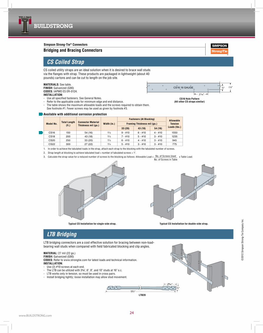
BUILDSTRONG
www.BUILDSTRONG.com24
10
©20
12 S
imps
on S
trong
‑Tie
Com
pany
Inc.
Simpson Strong-Tie® Connectors
For more information, please contact Telling Industries® at 1-866-372-6384
This technical information reflects the most current information available and supersedes any and all previous publications effective September 2011 #TEL2‑9/2011
1. In order to achieve the tabulated loads in the strap, attach each strap to the blocking with the tabulated number of screws.
2. Strap length at blocking to achieve tabulated load = number of tabulated screws + 1".
3. Calculate the strap value for a reduced number of screws to the blocking as follows: Allowable Load = No. of Screws Used x Table Load.
Bridging and Bracing Connectors
LTB Bridging
1¼”½“
21∕16”
CS16 16 GAUGE
CS16 hole Pattern(All other CS straps similar)
CS Coiled Strap
Available with additional corrosion protection
Model No.Total Length
(ft.)Connector Material Thickness mil (ga.)
Width (in.)
Fasteners (At Blocking) Allowable Tension
Loads (lbs.)Framing Thickness mil (ga.)
33 (20) 43 (18) 54 (16)
CS16 150 54 (16) 1¼ 9 - #10 6 - #10 4 - #10 1550
CS18 200 43 (18) 1¼ 7 - #10 5 - #10 3 - #10 1235
CS20 250 33 (20) 1¼ 6 - #10 4 - #10 3 - #10 945
CS22 300 27 (22) 1¼ 5 - #10 3 - #10 3 - #10 775
Typical CS Installation for single-side strap. Typical CS Installation for double-side strap.
LTB20
No. of Screws in Table
CS coiled utility straps are an ideal solution when it is desired to brace wall studs via the flanges with strap. These products are packaged in lightweight (about 40 pounds) cartons and can be cut to length on the job site.
MATerIALS: See table.FINISh: Galvanized (G90)CODeS: IAPMO ES ER‑0124.INSTALLATION: ‑ Use all specified fasteners. See General Notes. ‑ Refer to the applicable code for minimum edge and end distance. ‑ The table shows the maximum allowable loads and the screws required to obtain them.
See footnote #1. Fewer screws may be used as given by footnote #3.
LTB bridging connectors are a cost effective solution for bracing between non‑load‑bearing wall studs when compared with field fabricated blocking and clip angles.
MATerIAL: 27 mil (22 ga.)FINISh: Galvanized (G90)CODeS: Refer to www.strongtie.com for latest loads and technical information.INSTALLATION: ‑ Use (2) #10 screws at each end. ‑ The LTB can be utilized with 3⅝", 6", 8", and 10" studs at 16" o.c. ‑ LTB works only in tension, so must be used in cross pairs. ‑ Install bridging tightly; loose installation may allow stud movement.

INTERIOR FRAMING
0920025
ACCESSORIES AND FINISHING SYSTEMS
physical/Structural properties for Drywall Furring Channels (DwFC)
Drywall Furring Channel (DwFC) Allowable Ceiling Spans - l/240
Drywall Furring Channel (DwFC) Allowable Ceiling Spans - l/360
Gross Properties Effective Properties
SectionFy
(ksi)
DesignThickness
(in)Area(in2)
Weight(lb/ft)
Ix(in4)
Rx(in)
Iy(in4)
Ry(in)
Ix(in4)
Sx(in3)
Ma(Ft-lb)
DWFC088-18 33 0.0188 0.070 0.239 0.009 0.356 0.035 0.710 0.009 0.016 26.4DWFC088-30 33 0.0312 0.115 0.391 0.014 0.353 0.058 0.710 0.014 0.031 50.5DWFC088-43 33 0.0451 0.162 0.550 0.020 0.348 0.082 0.711 0.020 0.042 69.2DWFC088-54 50 0.0566 0.197 0.669 0.023 0.345 0.099 0.711 0.023 0.050 124.9DWFC150-18 33 0.0188 0.094 0.320 0.031 0.575 0.047 0.705 0.030 0.034 56.6DWFC150-30 33 0.0312 0.154 0.525 0.050 0.571 0.077 0.705 0.050 0.064 105.3DWFC150-43 33 0.0451 0.219 0.745 0.070 0.565 0.109 0.705 0.070 0.089 146.3DWFC150-54 50 0.0566 0.269 0.914 0.084 0.561 0.134 0.705 0.084 0.107 267.2
Uniform Load 4 psf 6 psf 13 psf
SectionFy
(ksi) SpansSpacing (in) oc Spacing (in) oc Spacing (in) oc
12 16 24 12 16 24 12 16 24
DWFC088-18 33Single 5’-2” 4’-9” 4’-1” 4’-6” 4’-1” 3’-7” 3’-6” 3’-2” 2’-9”
Multiple 6’-5” 5’-10” 5’-1” 5’-7” 5’-1” 4’-2” 4’-0” 3’-6” 2’-9”
DWFC088-30 33 Single 6’-2” 5’-7” 4’-11” 5’-5” 4’-11” 4’-3” 4’-2” 3’-9” 3’-4”Multiple 7’-7” 6’-11” 6’-1” 6’-8” 6’-1” 5’-3” 5’-2” 4’-8” 3’-11”
DWFC088-43 33 Single 6’-10” 6’-3” 5’-5” 6’- 0” 5’-5” 4’-9” 4’-7” 4’-2” 3’-8”Multiple 8’-6” 7’-8” 6’-9” 7’-5” 6’-9” 5’-10” 5’-9” 5’-2” 4’-6”
DWFC088-54 50 Single 7’-3” 6’-7” 5’-9” 6’-4” 5’-9” 5’-0” 4’-11” 4’-5” 3’-11”Multiple 9’- 0” 8’-2” 7’-2” 7’-10” 7’-2” 6’-3” 6’-1” 5’-6” 4’-10”
DWFC150-18 33 Single 7’-11” 7’-2” 6’-3” 6’-11” 6’-3” 5’-6” 5’-4” 4’-10” 4’-2”Multiple 9’-9” 8’-10” 7’-5” 8’-6” 7’-5” 5’-11” 5’-7” 4’-9” 3’-8”
DWFC150-30 33 Single 9’-5” 8’-6” 7’-5” 8’-2” 7’-5” 6’-6” 6’-4” 5’-9” 5’-0”Multiple 11’-7” 10’-6” 9’-2” 10’-2” 9’-2” 8’-0” 7’-10” 7’- 0” 5’-8”
DWFC150-43 33 Single 10’-6” 9’-6” 8’-4” 9’-2” 8’-4” 7’-3” 7’-1” 6’-5” 5’-7”Multiple 12’-11” 11’-9” 10’-3” 11’-4” 10’-3” 9’- 0” 8’-9” 7’-11” 6’-8”
DWFC150-54 50 Single 11’-2” 10’-1” 8’-10” 9’-9” 8’-10” 7’-9” 7’-6” 6’-10” 6’- 0”13’-9” 12’-6” 10’-11” 12’-0” 10’-11” 9’-7” 9’-4” 8’-5” 7’-5”
Notes: 1. Properties based on the 2007 NASPEC, and comply with 2006, 2009, and 2012 International Building Codes. 2. Design thickness used for determination of properties. Minimum delivered thickness must be no less than 95% of design thickness. 3. For deflection calculations, use effective Ixx. Effective Ixx is based on Procedure 1 of the NASPEC 4. Effective properties are given as the minimum value for positive or negative bending.
Notes: 1. Single spans taken as the minimum span based on moment, shear, web crippling or deflection 2. Multiple spans indicate two or more equal, continuous spans with span length measured support to support. 3. Multiple spans taken as the minimum span based on moment, shear, web crippling, deflection combined bending and shear or combined and web crippling 4. Web crippling values based on 1” bearing at end and interior supports.
Uniform Load 4 psf 6 psf 13 psf
Fy Spacing (in) oc Spacing (in) oc Spacing (in) ocSection (ksi) Spans 12 16 24 12 16 24 12 16 24
DFWC088-18 33 Single 4’-6” 4’-1” 3’-7” 4’- 0” 3’-7” 3’-2” 3’-1” 2’-9” 2’-5”Multiple 5’-7” 5’-1” 4’-5” 4’-11” 4’-5” 3’-11” 3’-9” 3’-5” 2’-9”
DWFC088-30 33 Single 5’-5” 4’-11” 4’-3” 4’-8” 4’-3” 3’-9” 3’-8” 3’-4” 2’-11”Multiple 6’-8” 6’-1” 5’-3” 5’-10” 5’-3” 4’-7” 4’-6” 4’-1” 3’-7”
DWFC088-43 33 Single 6’- 0” 5’-5” 4’-9” 5’-3” 4’-9” 4’-2” 4’-0” 3’-8” 3’-2”Multiple 7’-5” 6’-9” 5’-10” 6’-6” 5’-10” 5’-2” 5’- 0” 4’-6” 4’- 0”
DWFC088-54 50 Single 6’-4” 5’-9” 5’-0” 5’-7” 5’-0” 4’-5” 4’-3” 3’-11” 3’-5”Multiple 7’-10” 7’-2” 6’-3” 6’-10” 6’-3” 5’-5” 5’-4” 4’-10” 4’-2”
DWFC150-18 33 Single 6’-11” 6’-3” 5’-6” 6’-0” 5’-6” 4’-9” 4’-8” 4’-3” 3’-8”Multiple 8’-6” 7’-9” 6’-9” 7’-5” 6’-9” 5’-11” 5’-7” 4’-9” 3’-8”
DWFC150-30 33 Single 8’-2” 7’-5” 6’-6” 7’-2” 6’-6” 5’-8” 5’-6” 5’-0” 4’-5”Multiple 10’-2” 9’-2” 8’-0” 8’-10” 8’-0” 7’-0” 6’-10” 6’-3” 5’-5”
DFWC150-43 33 Single 9’-2” 8’-4” 7’-3” 8’- 0” 7’-3” 6’-4” 6’-2” 5’-7” 4’-11”Multiple 11’-4” 10’-3” 9’- 0” 9’-11” 9’- 0” 7’-10” 7’-8” 6’-11” 6’-1”
DFWC150-54 50 Single 9’-9” 8’-10” 7’-9” 8’-6” 7’-9” 6’-9” 6’-7” 6’- 0” 5’-3”12’-0” 10’-11” 9’-7” 10’-6” 9’-7” 8’-4” 8’-2” 7’-5” 6’-5”
product Data:• Available in 7/8” and 1-1/2” sizes.• Gauge: Standard 25 through 16 gauges.• Available in galvanized steel conforming to ASTM A1003, ASTM A653, and ASTM C645.• Lengths: 12’ 0” Stock Length, (other lengths available).• Consult Telling Industries’ Light Gage Structural Framing & Accessories brochure for structural properties and span tablesuses:• Convenient accessory components for use in furring out ceilings and masonry walls. Knurled face prevents screw “ride” when attaching gypsum wallboard.• 1-1/2” DWFC is economical with respect to furring walls with electrical boxes, (no need to set into concrete).

BUILDSTRONG
www.BUILDSTRONG.com26
ACCESSORIES AND FINISHING SYSTEMSproduct Data:• Available in galvanized steel meeting ASTM A1003 and hot-dipped galvanized steel meeting ASTM A653, G60.• Lengths: 16’ stock length. (Other lengths available)uses:• Bridging, (lateral support) in walls carrying axial and/or wind loads.• Bracing studs at door bucks and furring for ceilings.• Used in conjunction with metal lath and plaster in partitions, ceilings, column and beam enclosures, etc.
product Data:• RC-1: Single Leg • RC-2: Double Leg• Gauge: Standard 25 gage conforming to ASTM A653, C645 and ASTM A1003.• Lengths: 12’ 0” stock length• RC-1: Screw attachment, one side only.• RC-2: Screw attachment, both sides.uses:• Used as cross furring members for resilient attachment ofgypsum wallboard or lath on ceilings and partitions.• Decreases sound transmission through wall partitions and ceilings.
product length wt./Ft. pcs./Ctn. Ft./Ctn.RC-1 12’ 0.20 40 480RC-2 12’ 0.24 40 480
Notes: 1 Minimum deliverable base metal thickness is 95% of design thickness. 2 Inside bend radius taken as 3/32”. 3 Effective properties based on Fy = 33 ksi. 4 For deflection calculations, use the effective moment of inertia.
Notes: 1 Multiple span indicates two or more equal spans with channel continuous over interior supports. 2 End and interior bearing length = 0.75”. Web stiffeners are not required. 3 Listed spans are based on unbraced compression flanges. 4 Moment of inertia for deflection is calculated at the maximum service level stress for the span and load listed. Note that this value may be higher than the effective Ixx listed in section property tables.
Design Gross Effective Properties 33 ksiThickness Area Weight Ix Rx Iy Ry Ix Sx Ma Va
Section (in) (in2) (lb/ft) (in4) (in) (in4) (in) (in4) (in3) (in-k) (lb)CRC-075 0.0566 0.087 0.30 0.007 0.288 0.002 0.155 0.007 0.019 0.45 315CRC-150 0.0566 0.129 0.44 0.039 0.547 0.003 0.144 0.039 0.052 1.22 840CRC-200 0.0566 0.157 0.54 0.079 0.709 0.003 0.136 0.079 0.079 1.87 1190CRC-250 0.0566 0.186 0.63 0.139 0.866 0.003 0.128 0.139 0.111 2.64 1540
Allowable u-Channel (CRC) Ceiling Spans - l/240
Allowable u-Channel (CRC) Ceiling Spans - l/360
u-Channel (CRC) properties and Spans
4 psf 6 psf 13 psf
15 psf
Channel Spacing (in) o.c. Channel Spacing (in) o.c. Channel Spacing (in) o.c. Channel Spacing (in) o.c.Section Spans 24 36 48 60 72 24 36 48 60 72 24 36 48 60 72 24 36 48 60 72
CRC-075 Single 3’ 11” 3’ 5” 3’ 1” 2’ 10” 2’ 8” 3’ 5” 3’ 0” 2’ 8” 2’ 6” 2’ 4” 2’ 7” 2’ 4” 2’ 1” 1’ 11” 1’ 9” 2’ 6” 2’ 2” 2’ 0” 1’ 10” 1’ 8”Multiple 4’ 10” 4’ 2” 3’ 10” 3’ 7” 3’ 4” 4’ 2” 3’ 8” 3’ 4” 3’ 1” 2’ 10” 3’ 3” 2’ 9” 2’ 4” 2’ 1” 1’ 11” 3’ 1” 2’ 7” 2’ 2” 2’ 0” 1’ 9”
CRC-150 Single 5’ 6” 4’ 10” 4’ 5” 4’ 1” 3’ 10” 4’ 10” 4’ 3” 3’ 10” 3’ 7” 3’ 5” 3’ 9” 3’ 3” 3’ 0” 2’ 9” 2’ 7” 3’ 7” 3’ 2” 2’ 10” 2’ 7” 2’ 5”Multiple 7’ 1” 6’ 2” 5’ 8” 5’ 3” 4’ 11” 6’ 2” 5’ 5” 4’ 11” 4’ 7” 4’ 4” 4’ 10” 4’ 2” 3’ 9” 3’ 4” 3’ 0” 4’ 7” 4’ 0” 3’ 6” 3’ 1” 2’ 9”
CRC-200 Single 5’ 10” 5’ 1” 4’ 8” 4’ 4” 4’ 1” 5’ 1” 4’ 6” 4’ 1” 3’ 10” 3’ 7” 4’ 0” 3’ 6” 3’ 2” 3’ 0” 2’ 10” 3’ 10” 3’ 4” 3’ 1” 2’ 10” 2’ 8”Multiple 7’ 5” 6’ 6” 5’ 11” 5’ 6” 5’ 2” 6’ 6” 5’ 8” 5’ 2” 4’ 10” 4’ 7” 5’ 1” 4’ 5” 4’ 0” 3’ 9” 3’ 6” 4’ 10” 4’ 3” 3’ 10” 3’ 7” 3’ 2”
CRC-250 Single 6’ 1” 5’ 4” 4’ 10” 4’ 6” 4’ 3” 5’ 4” 4’ 8” 4’ 3” 4’ 0” 3’ 9” 4’ 2” 3’ 8” 3’ 4” 3’ 1” 2’ 11” 4’ 0” 3’ 6” 3’ 2” 3’ 0” 2’ 10” 7’ 9” 6’ 9” 6’ 2” 5’ 9” 5’ 5” 6’ 9” 5’ 11” 5’ 5” 5’ 0” 4’ 9” 5’ 3” 4’ 7” 4’ 3” 3’ 11” 3’ 9” 5’ 0” 4’ 5” 4’ 0” 3’ 9” 3’ 7”
4 psf 6 psf 13 psf 15 psfChannel Spacing (in) o.c. Channel Spacing (in) o.c. Channel Spacing (in) o.c. Channel Spacing (in) o.c.
Section Spans 24 36 48 60 72 24 36 48 60 72 24 36 48 60 72 24 36 48 60 72
CRC-075 Single 3’ 5” 3’ 0” 2’ 8” 2’ 6” 2’ 4” 3’ 0” 2’ 7” 2’ 4” 2’ 2” 2’ 1” 2’ 4” 2’ 0” 1’ 10” 1’ 8” 1’ 7” 2’ 2” 1’ 11” 1’ 9” 1’ 7” 1’ 6”Multiple 4’ 2” 3’ 8” 3’ 4” 3’ 1” 2’ 11” 3’ 8” 3’ 2” 2’ 11” 2’ 8” 2’ 7” 2’ 10” 2’ 6” 2’ 3” 2’ 1” 1’ 11” 2’ 8” 2’ 4” 2’ 2” 2’ 0” 1’ 9”
CRC-150 Single 5’ 6” 4’ 10” 4’ 5” 4’ 1” 3’ 10” 4’ 10” 4’ 3” 3’ 10” 3’ 7” 3’ 5” 3’ 9” 3’ 3” 3’ 0” 2’ 9” 2’ 7” 3’ 7” 3’ 2” 2’ 10” 2’ 7” 2’ 5”Multiple 7’ 1” 6’ 2” 5’ 8” 5’ 3” 4’ 11” 6’ 2” 5’ 5” 4’ 11” 4’ 7” 4’ 4” 4’ 10” 4’ 2” 3’ 9” 3’ 4” 3’ 0” 4’ 7” 4’ 0” 3’ 6” 3’ 1” 2’ 9”
CRC-200 Single 5’ 10” 5’ 1” 4’ 8” 4’ 4” 4’ 1” 5’ 1” 4’ 6” 4’ 1” 3’ 10” 3’ 7” 4’ 0” 3’ 6” 3’ 2” 3’ 0” 2’ 10” 3’ 10” 3’ 4” 3’ 1” 2’ 10” 2’ 8”Multiple 7’ 5” 6’ 6” 5’ 11” 5’ 6” 5’ 2” 6’ 6” 5’ 8” 5’ 2” 4’ 10” 4’ 7” 5’ 1” 4’ 5” 4’ 0” 3’ 9” 3’ 6” 4’ 10” 4’ 3” 3’ 10” 3’ 7” 3’ 2”
CRC-250 Single 6’ 1” 5’ 4” 4’ 10” 4’ 6” 4’ 3” 5’ 4” 4’ 8” 4’ 3” 4’ 0” 3’ 9” 4’ 2” 3’ 8” 3’ 4” 3’ 1” 2’ 11” 4’ 0” 3’ 6” 3’ 2” 3’ 0” 2’ 10” 7’ 9” 6’ 9” 6’ 2” 5’ 9” 5’ 5” 6’ 9” 5’ 11” 5’ 5” 5’ 0” 4’ 9” 5’ 3” 4’ 7” 4’ 3” 3’ 11” 3’ 9” 5’ 0” 4’ 5” 4’ 0” 3’ 9” 3’ 7”

INTERIOR FRAMING
0920027
Design Gross Effective Properties 33 ksiThickness Area Weight Ix Rx Iy Ry Ix Sx Ma Va
Section (in) (in2) (lb/ft) (in4) (in) (in4) (in) (in4) (in3) (in-k) (lb)CRC-075 0.0566 0.087 0.30 0.007 0.288 0.002 0.155 0.007 0.019 0.45 315CRC-150 0.0566 0.129 0.44 0.039 0.547 0.003 0.144 0.039 0.052 1.22 840CRC-200 0.0566 0.157 0.54 0.079 0.709 0.003 0.136 0.079 0.079 1.87 1190CRC-250 0.0566 0.186 0.63 0.139 0.866 0.003 0.128 0.139 0.111 2.64 1540
4 psf 6 psf 13 psf 15 psfChannel Spacing (in) o.c. Channel Spacing (in) o.c. Channel Spacing (in) o.c. Channel Spacing (in) o.c.
Section Spans 24 36 48 60 72 24 36 48 60 72 24 36 48 60 72 24 36 48 60 72
CRC-075 Single 3’ 5” 3’ 0” 2’ 8” 2’ 6” 2’ 4” 3’ 0” 2’ 7” 2’ 4” 2’ 2” 2’ 1” 2’ 4” 2’ 0” 1’ 10” 1’ 8” 1’ 7” 2’ 2” 1’ 11” 1’ 9” 1’ 7” 1’ 6”Multiple 4’ 2” 3’ 8” 3’ 4” 3’ 1” 2’ 11” 3’ 8” 3’ 2” 2’ 11” 2’ 8” 2’ 7” 2’ 10” 2’ 6” 2’ 3” 2’ 1” 1’ 11” 2’ 8” 2’ 4” 2’ 2” 2’ 0” 1’ 9”
CRC-150 Single 5’ 6” 4’ 10” 4’ 5” 4’ 1” 3’ 10” 4’ 10” 4’ 3” 3’ 10” 3’ 7” 3’ 5” 3’ 9” 3’ 3” 3’ 0” 2’ 9” 2’ 7” 3’ 7” 3’ 2” 2’ 10” 2’ 7” 2’ 5”Multiple 7’ 1” 6’ 2” 5’ 8” 5’ 3” 4’ 11” 6’ 2” 5’ 5” 4’ 11” 4’ 7” 4’ 4” 4’ 10” 4’ 2” 3’ 9” 3’ 4” 3’ 0” 4’ 7” 4’ 0” 3’ 6” 3’ 1” 2’ 9”
CRC-200 Single 5’ 10” 5’ 1” 4’ 8” 4’ 4” 4’ 1” 5’ 1” 4’ 6” 4’ 1” 3’ 10” 3’ 7” 4’ 0” 3’ 6” 3’ 2” 3’ 0” 2’ 10” 3’ 10” 3’ 4” 3’ 1” 2’ 10” 2’ 8”Multiple 7’ 5” 6’ 6” 5’ 11” 5’ 6” 5’ 2” 6’ 6” 5’ 8” 5’ 2” 4’ 10” 4’ 7” 5’ 1” 4’ 5” 4’ 0” 3’ 9” 3’ 6” 4’ 10” 4’ 3” 3’ 10” 3’ 7” 3’ 2”
CRC-250 Single 6’ 1” 5’ 4” 4’ 10” 4’ 6” 4’ 3” 5’ 4” 4’ 8” 4’ 3” 4’ 0” 3’ 9” 4’ 2” 3’ 8” 3’ 4” 3’ 1” 2’ 11” 4’ 0” 3’ 6” 3’ 2” 3’ 0” 2’ 10” 7’ 9” 6’ 9” 6’ 2” 5’ 9” 5’ 5” 6’ 9” 5’ 11” 5’ 5” 5’ 0” 4’ 9” 5’ 3” 4’ 7” 4’ 3” 3’ 11” 3’ 9” 5’ 0” 4’ 5” 4’ 0” 3’ 9” 3’ 7”
ACCESSORIES AND FINISHING SYSTEMSproduct Data:• Available in hot-dipped galvanized steel conforming to ASTM A653, C645 and A1003.• Gauges: Standard 25 gauge, (available in 20, 18, and 16 gauge upon request).• Lengths: Standard 10’ 0” and 8’ 6” lengths, (other lengths available upon request).uses:• Designed to accommodate the installation of rigid insulation board while pro viding an attachment for drywall or other facing materials to the interior side of masonry or monolithic concrete walls.
product (A) in. Size 25 ga. wt./Ft.Z-100 1.00 0.195Z-150 1.50 0.225Z-200 2.00 0.260
product Data:• Designation: FS width and gauge.• Widths: 2, 4 and 6” (custom widths and coil available).uses:• Provides tension force resistance in shear wall assemblies.• Resists racking of prefabricated wall assemblies while handling, transporting, and erecting.
product width (in.) gauges lengthFS 2”, 4”, 6” 25, 22, 20, 18, 16 10’
product Data:• Made of galvanized steel.• Joint cement adheres easily to knurled flanges and keys into the perforations.• Exposed nose provides a straight, clean corner definition and guards against damage through impact .uses:• Provides durable protection for drywall external corners.• Specify hot-dipped for moist or humid conditions.
(RA) Rolled Angles
(CA) Clip Angles
Product Data:• Available in most sizes, lengths, and gauges.
Uses:• For 90 degree corner enclosures at lapped framing location; provides in-plane stability of framework.
Product Data:• Designation: SA Length (L) x gauge.• Designed for 3-5/8, 4, 6, 7-1/4, 8, 9-1/4, 10 and 12 inch studs.• Gauges: 18 ga (3-5/8, 4, or 6 inch only), 14 ga (all lengths), 12 ga (6, 7-1/4, 8, 9-1/4, 10 and 12 inch only)• W and F dimensions per request. Standard 2” x 2”
Uses:• For miscellaneous attachments of intersecting framing components.• For attachment of joist framing components to flush mounted headers.• For attachment of solid blocking sections to adjacent studs of joists.• For alternate screw attachment of CRC briding to stud webs in lieu direct weld

BUILDSTRONG
www.BUILDSTRONG.com28
ACCESSORIES AND FINISHING SYSTEMSproduct Data:• Sturdy, channel-type steel casing.• Joint cement applied to front side.• L Bead available in both regular and long-leg flange.• Easily installs to framing or jamb.uses:• Provides maximum protection.• Adds a finished edge to wallboard at window and door jambs
product Size Depth length(ft.) pcs./Ctn. Ft./Ctn.L-50, J-50 1/2” or 5/8” 8’, 10’ 63, 50 5 04, 500L-62, J-62 “ “ “ “
Custom lengths and UPC labeling available upon request.
product Data:• An economical steel channel.• No joint cement required.uses:• Provides edge protection around doors and windows or any partition junction openings.
product Size Depth length(ft.) pcs./Ctn. Ft./Ctn.RT-50, RT-62 1/2” & 5/8” 8’, 10’ 63, 50 504, 500
Custom lengths and UPC labeling available upon request.
product Data:• Manufactured from the highest quality pure zinc coil stock for superior corrosion resistance.• Fits standard 1⁄4” openings.uses:• Product is excellent for interior or exterior applications.
product length(ft.) pcs./Ctn. Ft./Ctn.093 10’ 25 250

INTERIOR FRAMING
0920029
ACCESSORIES AND FINISHING SYSTEMS
WWW.BUILDSTRONG.COM