Embed Size (px)
Citation preview
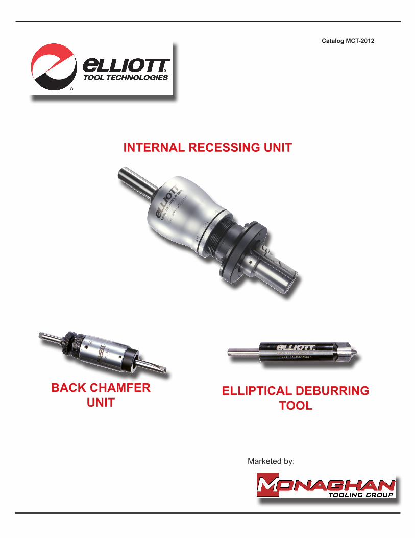
Catalog MCT-2012
INTERNAL RECESSING UNIT
BACK CHAMFER UNIT
ELLIPTICAL DEBURRING TOOL
Marketed by:

ELLIOTT INTERNAL RECESSING UNITIRUThe Internal Recessing Unit is the most efficient method of machining single or multiple grooves in one operation. The Elliott system is comprised of an operating head, pilot, carrier arm and replaceable form ground cutter.
ZERO DEFLECTIONDue to the unique design, the cutter is supported along it’s entire length by the pilot. This eliminates deflection and ensures precise feature machining with consistent repeatability.
OPERATING PROCEDUREThe recess system feeds into the work-piece with the pilot locating within the component bore. The operating head or optional nose piece makes contact with either the component face or a fixture plate. While feeding forward, the system is actuated, lifting the cutter exactly perpendicular to the axis of rotation at a 2:1 ratio. This machines all features simultaneously, with perfect concentricity. Radial cut depth can be controlled by the limiting nut bottoming out or by the CNC program controlling the tool’s feed-depth.
FEED FEEDAND
RETRACTRAPID FEED
INTO COMPONENT
2

OD
5.109”
TYPICAL APPLICATIONS
LAND MACHINING HYDRAULIC SPOOL
VALVES IN ONE PASS
Pilot length tosuit application
COOLANT THROUGH
SHANK
ELLIOTT INTERNAL RECESSING UNIT
1. Location Pilot (OD ground to suit component bore) 2. Cutter (Replaceable on carrier arm) 3. Adjustment Stop Collar (Actuate IRU with adjustable length of up to .780”) 4. Operating Head Assembly
STANDARD FEATURES AVAILABLE: 1. Straight Shank (3/4” and 1” diameter with through coolant) 2. Morse Taper Shank (#2 and #3) 3. Automotive Shanks Available 4. Override Adapter Available
1 2 3 4
3

INSTALLING IRU PILOTS AND ARMS
TOOL SETTING There are only two settings required on the Elliott IRU tool:• Positional Location of the groove is referenced from the face of the stop-collar and/or
nose piece to a qualified land on the part or fixture. This position is accomplished by fine threading the adjustable stop collar. A height gauge is the best way to measure the linear position of the cutter in relation to the stop collar or nose piece.
• Groove Diameter on a manual fed machine is accomplished by adjusting the limiting nut on the shank end of the tool. For CNC or power fed machines, this is accomplished by programming. It should be noted that the radial feed-out of the IRU is 2:1. If .002” increase of cut diameter is needed, add .002” to the linear travel. Tool diameter can be measured with a micrometer by actuating the tool to the cutting position. Measure the diameter of the pilot and add 2x the height of the cutter.
INTERNAL RECESSING UNIT
Lock the pilot in place with the screw, as shown. When the adjustment stop collar is in place, this screw is tightened through a slot in the collar.
Hold the cutter or the carrier arm with cutter attached at 90° to the leaf spring and insert it into the operating head.
Rotate the cutter 90° degrees so that the yoke of the cutter straddles the pull pin. The leaf spring will come to rest on the pad of the arm as shown.
Align the pilot to the cutter and insert the pilot until the cam surface of the cutter engages the pilot.
FEEDS AND SPEEDS• Feed rates of .003 to .005 IPR are typical starting points for most applications. For smaller bore
diameters (less than 1/2”), decrease the feed rate below .003 IPR. • Surface feet per minute are equal to those recommended for multi-fluted reamers (the speeds
below can be increased up to 3x):
MATERIAL MACHINED SFM Cast Iron - Gray 100 to 110 Cast Iron - Nodular 30 to 40 Steel / Forgings 35 to 40 Aluminum and Brass 150 to 160
4

ELLIPTICAL DEBURRING TOOL
Part diameter should be at least three times greater than the cross drilled hole.
Use at low speeds on drills, drill presses or automated machines.
FOR CURVED OR ELLIPTICALSURFACES CREATED IN DRILLING
• FOLLOWS HOLE CIRCUMFERENCE
• UNIFORM BURR REMOVAL
• REGRINDABLE CUTTERS
• TOOL SIZES 5/32” TO 1”
• MADE OF M42 HSS TiN COATED
5
E
D
A B
CF°
Preferred method of deburring crankshaft oil holes

Ordering Information: Please supply details of the component and the chamfer form required.
• Fast and easy way to machine precise back chamfers.
• Cycle time measured in seconds, not minutes.
• Positive deburring the rear of a hole from the front face. • Use on manual drills, special purpose and CNC machines. • Standard cutters available in M2 HSS to machine 45° chamfer. Special
chamfer angles, radii and premium HSS quoted on request.
• Standard BCU products chamfer hole diameters from .187” to .750”. Other sizes quoted on request.
• Standard reaches available are 1” (25.4mm) and 1.77” (45mm). Longer lengths quoted on request.
BACK CHAMFERING UNIT
RAPID FEEDINTO THECOMPONENT
FEED FEED ANDRETRACT
6
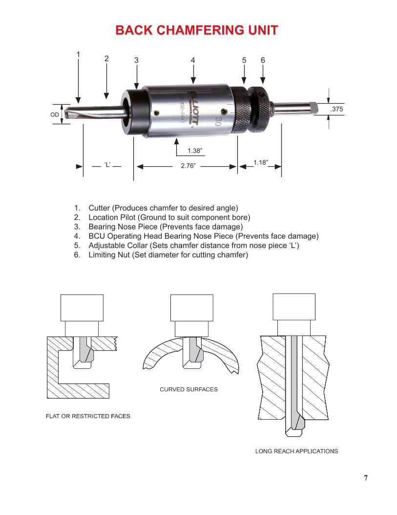
1. Cutter (Produces chamfer to desired angle) 2. Location Pilot (Ground to suit component bore) 3. Bearing Nose Piece (Prevents face damage) 4. BCU Operating Head Bearing Nose Piece (Prevents face damage) 5. Adjustable Collar (Sets chamfer distance from nose piece ‘L’) 6. Limiting Nut (Set diameter for cutting chamfer)
BACK CHAMFERING UNIT
213 4 65
1.38”
1.18”‘L’ 2.76”
7
OD.375
www.elliott-tool.com
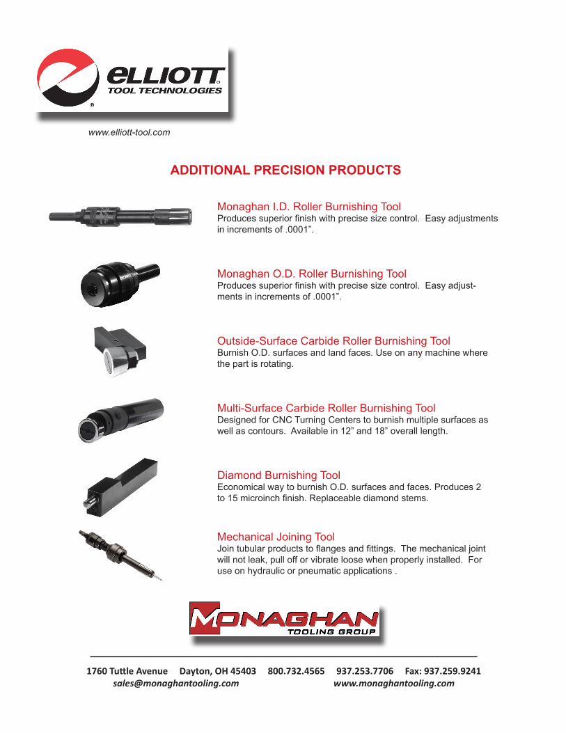
Monaghan O.D. Roller Burnishing ToolProduces superior finish with precise size control. Easy adjust-ments in increments of .0001”.
ADDITIONAL PRECISION PRODUCTS
Monaghan I.D. Roller Burnishing ToolProduces superior finish with precise size control. Easy adjustments in increments of .0001”.
Outside-Surface Carbide Roller Burnishing Tool Burnish O.D. surfaces and land faces. Use on any machine where the part is rotating.
Multi-Surface Carbide Roller Burnishing Tool Designed for CNC Turning Centers to burnish multiple surfaces as well as contours. Available in 12” and 18” overall length.
Diamond Burnishing Tool Economical way to burnish O.D. surfaces and faces. Produces 2 to 15 microinch finish. Replaceable diamond stems.
Mechanical Joining Tool Join tubular products to flanges and fittings. The mechanical joint will not leak, pull off or vibrate loose when properly installed. For use on hydraulic or pneumatic applications .
1760 Tuttle Avenue Dayton, OH 45403 800.732.4565 937.253.7706 Fax: 937.259.9241 [email protected] www.monaghantooling.com