Embed Size (px)
Citation preview

Electromagnetic compatibility (EMC) –
Part 4-3: Testing and measurement techniques – Radiated, radio-frequency, electromagnetic field immunity test
Reference number IEC 61000-4-3:2006(E)
INTERNATIONAL STANDARD
IEC61000-4-3
Third edition2006-02
This English-language version is derived from the original bilingual publication by leaving out all French-language pages. Missing page numbers correspond to the French-language pages.
BASIC EMC PUBLICATION

Publication numbering
As from 1 January 1997 all IEC publications are issued with a designation in the 60000 series. For example, IEC 34-1 is now referred to as IEC 60034-1.
Consolidated editions
The IEC is now publishing consolidated versions of its publications. For example, edition numbers 1.0, 1.1 and 1.2 refer, respectively, to the base publication, the base publication incorporating amendment 1 and the base publication incorporating amendments 1 and 2.
Further information on IEC publications
The technical content of IEC publications is kept under constant review by the IEC, thus ensuring that the content reflects current technology. Information relating to this publication, including its validity, is available in the IEC Catalogue of publications (see below) in addition to new editions, amendments and corrigenda. Information on the subjects under consideration and work in progress undertaken by the technical committee which has prepared this publication, as well as the list of publications issued, is also available from the following:
• IEC Web Site (www.iec.ch)
• Catalogue of IEC publications
The on-line catalogue on the IEC web site (www.iec.ch/searchpub) enables you to search by a variety of criteria including text searches, technical committees and date of publication. On-line information is also available on recently issued publications, withdrawn and replaced publications, as well as corrigenda.
• IEC Just Published
This summary of recently issued publications (www.iec.ch/online_news/ justpub) is also available by email. Please contact the Customer Service Centre (see below) for further information.
• Customer Service Centre
If you have any questions regarding this publication or need further assistance, please contact the Customer Service Centre:
Email: [email protected] Tel: +41 22 919 02 11 Fax: +41 22 919 03 00

Electromagnetic compatibility (EMC) –
Part 4-3: Testing and measurement techniques – Radiated, radio-frequency, electromagnetic field immunity test
For price, see current catalogue
IEC 2006 Copyright - all rights reserved
No part of this publication may be reproduced or utilized in any form or by any means, electronic or mechanical, including photocopying and microfilm, without permission in writing from the publisher.
International Electrotechnical Commission, 3, rue de Varembé, PO Box 131, CH-1211 Geneva 20, SwitzerlandTelephone: +41 22 919 02 11 Telefax: +41 22 919 03 00 E-mail: [email protected] Web: www.iec.ch
INTERNATIONAL STANDARD
IEC61000-4-3
Third edition2006-02
XA Commission Electrotechnique InternationaleInternational Electrotechnical CommissionМеждународная Электротехническая Комиссия
PRICE CODE
BASIC EMC PUBLICATION

61000-4-3 IEC:2006 – 3 –
CONTENTS
FOREWORD...........................................................................................................................7 INTRODUCTION...................................................................................................................11 1 Scope and object............................................................................................................ 13 2 Normative references ..................................................................................................... 13 3 Terms and definitions ..................................................................................................... 15 4 General .......................................................................................................................... 21 5 Test levels ...................................................................................................................... 21
5.1 Test levels related to general purposes ................................................................. 23 5.2 Test levels related to the protection against RF emissions from digital radio
telephones and other RF emitting devices ............................................................. 23 6 Test equipment............................................................................................................... 25
6.1 Description of the test facility ................................................................................ 25 6.2 Calibration of field ................................................................................................. 27
7 Test setup ...................................................................................................................... 37 7.1 Arrangement of table-top equipment...................................................................... 37 7.2 Arrangement of floor-standing equipment .............................................................. 37 7.3 Arrangement of wiring ........................................................................................... 39 7.4 Arrangement of human body-mounted equipment .................................................. 39
8 Test procedure ............................................................................................................... 39 8.1 Laboratory reference conditions ............................................................................ 39 8.2 Execution of the test.............................................................................................. 41
9 Evaluation of test results ................................................................................................ 43 10 Test report...................................................................................................................... 43 Annex A (informative) Rationale for the choice of modulation for tests related to the protection against RF emissions from digital radio telephones .............................................. 61 Annex B (informative) Field generating antennas ................................................................. 71 Annex C (informative) Use of anechoic chambers ................................................................ 73 Annex D (informative) Amplifier non-linearity and example for the calibration procedure according to 6.2 ................................................................................................... 79 Annex E (informative) Guidance for product committees on the selection of test levels ........ 89 Annex F (informative) Selection of test methods .................................................................. 95 Annex G (informative) Description of the environment.......................................................... 97 Annex H (normative) Alternative illumination method for frequencies above 1 GHz (“independent windows method”) ........................................................................................ 107

61000-4-3 IEC:2006 – 5 –
Figure 1 – Definition of the test level and the waveshapes occurring at the output of the signal generator .............................................................................................................. 47 Figure 2 – Example of suitable test facility ............................................................................ 49 Figure 3 – Calibration of field ................................................................................................51 Figure 4 – Calibration of field, dimensions of the uniform field area ...................................... 53 Figure 5 – Example of test setup for floor-standing equipment .............................................. 55 Figure 6 – Example of test setup for table-top equipment...................................................... 57 Figure 7 – Measuring setup .................................................................................................. 59 Figure C.1 − Multiple reflections in an existing small anechoic chamber................................ 75 Figure C.2 − Most of the reflected waves are eliminated ....................................................... 77 Figure D.1 − Measuring positions of the uniform field area .................................................... 83 Figure H.1 – Examples of division of the calibration area into 0,5 m × 0,5 m windows ......... 109 Figure H.2 – Example of illumination of successive windows ............................................... 111
Table 1 – Test levels related to general purpose, digital radio telephones and other RF emitting devices .................................................................................................................... 21 Table 2 – Requirements for uniform field area for application of full illumination, partial illumination and independent windows method...................................................................... 29 Table A.1 − Comparison of modulation methods ................................................................... 63 Table A.2 − Relative interference levels ................................................................................ 65 Table A.3 − Relative immunity levels..................................................................................... 67 Table D.1 – Forward power values measured according to the constant field strength calibration method ................................................................................................................ 85 Table D.2 – Forward power values sorted according to rising value and evaluation of the measuring result ............................................................................................................. 85 Table D.3 – Forward power and field strength values measured according to the constant power calibration method........................................................................................ 87 Table D.4 – Field strength values sorted according to rising value and evaluation of the measuring result ................................................................................................................... 87 Table E.1 – Examples of test levels, associated protection distances and suggested performance criteria .............................................................................................................. 93 Table G.1 – Mobile and portable units................................................................................. 101 Table G.2 – Base stations................................................................................................... 103 Table G.3 – Other RF devices............................................................................................. 105

61000-4-3 IEC:2006 – 7 –
INTERNATIONAL ELECTROTECHNICAL COMMISSION _________
ELECTROMAGNETIC COMPATIBILITY (EMC) –
Part 4-3: Testing and measurement techniques –
Radiated, radio-frequency, electromagnetic field immunity test
FOREWORD 1) The International Electrotechnical Commission (IEC) is a worldwide organization for standardization comprising
all national electrotechnical committees (IEC National Committees). The object of IEC is to promote international co-operation on all questions concerning standardization in the electrical and electronic fields. To this end and in addition to other activities, IEC publishes International Standards, Technical Specifications, Technical Reports, Publicly Available Specifications (PAS) and Guides (hereafter referred to as “IEC Publication(s)”). Their preparation is entrusted to technical committees; any IEC National Committee interested in the subject dealt with may participate in this preparatory work. International, governmental and non-governmental organizations liaising with the IEC also participate in this preparation. IEC collaborates closely with the International Organization for Standardization (ISO) in accordance with conditions determined by agreement between the two organizations.
2) The formal decisions or agreements of IEC on technical matters express, as nearly as possible, an international consensus of opinion on the relevant subjects since each technical committee has representation from all interested IEC National Committees.
3) IEC Publications have the form of recommendations for international use and are accepted by IEC National Committees in that sense. While all reasonable efforts are made to ensure that the technical content of IEC Publications is accurate, IEC cannot be held responsible for the way in which they are used or for any misinterpretation by any end user.
4) In order to promote international uniformity, IEC National Committees undertake to apply IEC Publications transparently to the maximum extent possible in their national and regional publications. Any divergence between any IEC Publication and the corresponding national or regional publication shall be clearly indicated in the latter.
5) IEC provides no marking procedure to indicate its approval and cannot be rendered responsible for any equipment declared to be in conformity with an IEC Publication.
6) All users should ensure that they have the latest edition of this publication.
7) No liability shall attach to IEC or its directors, employees, servants or agents including individual experts and members of its technical committees and IEC National Committees for any personal injury, property damage or other damage of any nature whatsoever, whether direct or indirect, or for costs (including legal fees) and expenses arising out of the publication, use of, or reliance upon, this IEC Publication or any other IEC Publications.
8) Attention is drawn to the Normative references cited in this publication. Use of the referenced publications is indispensable for the correct application of this publication.
9) Attention is drawn to the possibility that some of the elements of this IEC Publication may be the subject of patent rights. IEC shall not be held responsible for identifying any or all such patent rights.
International Standard IEC 61000-4-3 has been prepared by subcommittee 77B: High frequency phenomenon, of IEC technical committee 77: Electromagnetic compatibility.
It forms part 4-3 of IEC 61000. It has the status of a basic EMC publication in accordance with IEC Guide 107, Electromagnetic compatibility – Guide to the drafting of electromagnetic compatibility publications.
This third edition cancels and replaces the first edition published in 2002 and its amendment 1 (2002), and constitutes a technical revision. The test frequency range may be extended up to 6 GHz to take account of new services. The calibration of the field as well as the checking of power amplifier linearity of the immunity chain are specified.

61000-4-3 IEC:2006 – 9 –
The text of this standard is based on the following documents:
FDIS Report on voting
77B/485/FDIS 77B/500/RVD
Full information on the voting for the approval of this standard can be found in the report on voting indicated in the above table.
This publication has been drafted in accordance with the ISO/IEC Directives, Part 2.
The committee has decided that the contents of this publication will remain unchanged until the maintenance result date indicated on the IEC web site under "http://webstore.iec.ch" in the data related to the specific publication. At this date, the publication will be
• reconfirmed;
• withdrawn;
• replaced by a revised edition, or
• amended.

61000-4-3 IEC:2006 – 11 –
INTRODUCTION
This standard is part of the IEC 61000 series, according to the following structure:
Part 1: General
General considerations (introduction, fundamental principles) Definitions, terminology
Part 2: Environment
Description of the environment Classification of the environment Compatibility levels
Part 3: Limits
Emission limits Immunity limits (in so far as they do not fall under the responsibility of the product committees)
Part 4: Testing and measurement techniques
Measurement techniques Testing techniques
Part 5: Installation and mitigation guidelines
Installation guidelines Mitigation methods and devices
Part 6: Generic standards
Part 9: Miscellaneous
Each part is further subdivided into several parts, published either as international standards or as technical specifications or technical reports, some of which have already been published as sections. Others will be published with the part number followed by a dash and a second number identifying the subdivision (example: 61000-6-1).
This part is an International Standard which gives immunity requirements and test procedures related to radiated, radio-frequency, electromagnetic fields.

61000-4-3 IEC:2006 – 13 –
ELECTROMAGNETIC COMPATIBILITY (EMC) –
Part 4-3: Testing and measurement techniques – Radiated, radio-frequency, electromagnetic field immunity test
1 Scope and object
This part of IEC 61000 is applicable to the immunity requirements of electrical and electronic equipment to radiated electromagnetic energy. It establishes test levels and the required test procedures.
The object of this standard is to establish a common reference for evaluating the immunity of electrical and electronic equipment when subjected to radiated, radio-frequency electro-magnetic fields. The test method documented in this part of IEC 61000 describes a consistent method to assess the immunity of an equipment or system against a defined phenomenon.
NOTE 1 As described in IEC Guide 107, this is a basic EMC publication for use by product committees of the IEC. As also stated in Guide 107, the IEC product committees are responsible for determining whether this immunity test standard should be applied or not, and if applied, they are responsible for determining the appropriate test levels and performance criteria. TC 77 and its sub-committees are prepared to co-operate with product committees in the evaluation of the value of particular immunity tests for their products.
This part deals with immunity tests related to the protection against RF electromagnetic fields from any source.
Particular considerations are devoted to the protection against radio-frequency emissions from digital radiotelephones and other RF emitting devices.
NOTE 2 Test methods are defined in this part for evaluating the effect that electromagnetic radiation has on the equipment concerned. The simulation and measurement of electromagnetic radiation is not adequately exact for quantitative determination of effects. The test methods defined are structured for the primary objective of establishing adequate repeatability of results at various test facilities for qualitative analysis of effects.
This standard is an independent test method. Other test methods may not be used as substitutes for claiming compliance with this standard.
2 Normative references
The following referenced documents are indispensable for the application of this document. For dated references, only the edition cited applies. For undated references, the latest edition of the referenced document (including any amendments) applies.
IEC 60050(161), International Electrotechnical Vocabulary (IEV) – Chapter 161: Electro-magnetic compatibility
IEC 61000-4-6, Electromagnetic compatibility (EMC) – Part 4-6: Testing and measurement techniques – Immunity to conducted disturbances, induced by radio-frequency fields

61000-4-3 IEC:2006 – 15 –
3 Terms and definitions
For the purposes of this part of IEC 61000, the following definitions, together with those in IEC 60050(161) apply.
3.1 amplitude modulation process by which the amplitude of a carrier wave is varied following a specified law
3.2 anechoic chamber shielded enclosure which is lined with radio-frequency absorbers to reduce reflections from the internal surfaces
3.2.1 fully anechoic chamber shielded enclosure whose internal surfaces are totally lined with anechoic material
3.2.2 semi-anechoic chamber shielded enclosure where all internal surfaces are covered with anechoic material with the exception of the floor, which shall be reflective (ground plane)
3.2.3 modified semi-anechoic chamber semi-anechoic chamber which has additional absorbers installed on the ground plane
3.3 antenna transducer which either emits radio-frequency power into space from a signal source or intercepts an arriving electromagnetic field, converting it into an electrical signal
3.4 balun device for transforming an unbalanced voltage to a balanced voltage or vice versa
[IEV 161-04-34]
3.5 continuous waves (CW) electromagnetic waves, the successive oscillations of which are identical under steady-state conditions, which can be interrupted or modulated to convey information
3.6 electromagnetic (EM) wave radiant energy produced by the oscillation of an electric charge characterized by oscillation of the electric and magnetic fields
3.7 far field region where the power flux density from an antenna approximately obeys an inverse square law of the distance.
For a dipole this corresponds to distances greater than λ /2π, where λ is the wavelength of the radiation

61000-4-3 IEC:2006 – 17 –
3.8 field strength The term "field strength" is applied only to measurements made in the far field. The measurement may be of either the electric or the magnetic component of the field and may be expressed as V/m, A/m or W/m2; any one of these may be converted into the others.
NOTE For measurements made in the near field, the term "electric field strength" or "magnetic field strength" is used according to whether the resultant electric or magnetic field, respectively, is measured. In this field region, the relationship between the electric and magnetic field strength and distance is complex and difficult to predict, being dependent on the specific configuration involved. Inasmuch as it is not generally feasible to determine the time and space phase relationship of the various components of the complex field, the power flux density of the field is similarly indeterminate.
3.9 frequency band continuous range of frequencies extending between two limits
3.10 Ec field strength applied for calibration
3.11 Et carrier field strength applied for testing
3.12 full illumination test method in which the EUT face being tested fits completely within the UFA (Uniform Field Area).
This test method may be applied for all test frequencies
3.13 human body-mounted equipment equipment which is intended for use when attached to or held in close proximity to the human body.
This term includes hand-held devices which are carried by people while in operation (e.g. pocket devices) as well as electronic aid devices and implants
3.14 independent windows method test method (using 0,5 m × 0,5 m UFA) in which the EUT face being tested does not fit completely within the UFA.
This test method may be applied for test frequencies greater than 1 GHz
3.15 induction field predominant electric and/or magnetic field existing at a distance d < λ /2π, where λ is the wavelength, and the physical dimensions of the source are much smaller than distance d
3.16 intentional RF emitting device device which radiates (transmits) an electromagnetic field intentionally. Examples include digital mobile telephones and other radio devices

61000-4-3 IEC:2006 – 19 –
3.17 isotropic having properties of equal values in all directions
3.18 maximum RMS value highest short-term RMS value of a modulated RF signal during an observation time of one modulation period.
The short-term RMS is evaluated over a single carrier cycle. For example, in Figure 1b), the maximum RMS voltage is:
Vmaximum RMS = Vp-p / (2 × 2 ) = 1,8 V
3.19 non-constant envelope modulation RF modulation schemes in which the amplitude of the carrier wave varies slowly in time compared with the period of the carrier itself. Examples include conventional amplitude modulation and TDMA
3.20 Pc forward power needed to establish the calibration field strength
3.21 partial illumination test method (using a minimum sized UFA of 1,5 × 1,5 m) in which the EUT face being tested does not fit completely within the UFA.
This test method may be applied for all test frequencies.
3.22 polarization orientation of the electric field vector of a radiated field
3.23 shielded enclosure screened or solid metal housing designed expressly for the purpose of isolating the internal from the external electromagnetic environment. The purpose is to prevent outside ambient electromagnetic fields from causing performance degradation and to prevent emission from causing interference to outside activities
3.24 sweep continuous or incremental traverse over a range of frequencies
3.25 TDMA (time division multiple access) time multiplexing modulation scheme which places several communication channels on the same carrier wave at an allocated frequency. Each channel is assigned a time slot during which, if the channel is active, the information is transmitted as a pulse of RF power. If the channel is not active no pulse is transmitted, thus the carrier envelope is not constant. During the pulse, the amplitude is constant and the RF carrier is frequency- or phase-modulated

61000-4-3 IEC:2006 – 21 –
3.26 transceiver combination of radio transmitting and receiving equipment in a common housing
3.27 uniform field area (UFA) hypothetical vertical plane of the field calibration in which variations are acceptably small.
The purpose of field calibration is to ensure the validity of the test result. See 6.2
4 General
Most electronic equipment is, in some manner, affected by electromagnetic radiation. This radiation is frequently generated by such general purpose sources as the small hand-held radio transceivers that are used by operating, maintenance and security personnel, fixed-station radio and television transmitters, vehicle radio transmitters, and various industrial electromagnetic sources.
In recent years there has been a significant increase in the use of radio telephones and other RF emitting devices operating at frequencies between 0,8 GHz and 6 GHz. Many of these services use modulation techniques with a non-constant envelope (e.g. TDMA). See 5.2.
In addition to electromagnetic energy deliberately generated, there is also radiation caused by devices such as welders, thyristors, fluorescent lights, switches operating inductive loads, etc. For the most part, this interference manifests itself as conducted electrical interference and, as such, is dealt with in other parts of the IEC 61000-4 standard series. Methods employed to prevent effects from electromagnetic fields will normally also reduce the effects from these sources.
The electromagnetic environment is determined by the strength of the electromagnetic field. The field strength is not easily measured without sophisticated instrumentation nor is it easily calculated by classical equations and formulas because of the effect of surrounding structures or the proximity of other equipment that will distort and/or reflect the electromagnetic waves.
5 Test levels
The test levels are given in Table 1.
Table 1 – Test levels related to general purpose, digital radio telephones and other RF emitting devices
Level Test field strength
V/m
1 1
2 3
3 10
4 30
x Special
NOTE x is an open test level and the associated field strength may be any value. This level may be given in the product standard.

61000-4-3 IEC:2006 – 23 –
This standard does not suggest that a single test level is applicable over the entire frequency range. Product committees shall select the appropriate test level for each frequency range needing to be tested as well as the frequency ranges. See Annex E for a guidance for product committees on the selection of test levels.
The test field strength column gives values of the unmodulated carrier signal. For testing of equipment, this carrier signal is 80 % amplitude modulated with a 1 kHz sine wave to simulate actual threats (see Figure 1). Details of how the test is performed are given in Clause 8.
5.1 Test levels related to general purposes
The tests are normally performed without gaps in the frequency range 80 MHz to 1 000 MHz.
NOTE 1 Product committees may decide to choose a lower or higher transition frequency than 80 MHz between IEC 61000-4-3 and IEC 61000-4-6 (see Annex G).
NOTE 2 Product committees may select alternative modulation schemes for equipment under test.
NOTE 3 IEC 61000-4-6 also defines test methods for establishing the immunity of electrical and electronic equipment against radiated electromagnetic energy. It covers frequencies below 80 MHz.
5.2 Test levels related to the protection against RF emissions from digital radio telephones and other RF emitting devices
The tests are normally performed in the frequency ranges 800 MHz to 960 MHz and 1,4 GHz to 6,0 GHz.
The frequencies or frequency bands to be selected for the test are limited to those where mobile radio telephones and other intentional RF emitting devices actually operate. It is not intended that the test needs to be applied continuously over the entire frequency range from 1,4 GHz to 6 GHz. For those frequency bands used by mobile radio telephones and other intentional RF emitting devices, specific test levels may be applied in the corresponding frequency range of operation.
Also if the product is intended to conform only to the requirements of particular countries, the measurement range 1,4 GHz to 6 GHz may be reduced to cover just the specific frequency bands allocated to digital mobile telephones and other intentional RF emitting devices in those countries. In this situation, the decision to test over reduced frequency ranges shall be documented in the test report.
NOTE 1 Annex A contains an explanation regarding the decision to use sine wave modulation for tests related to protection against RF emissions from digital radio telephones and other intentional RF emitting devices.
NOTE 2 Annex E contains guidance with regard to selecting test levels.
NOTE 3 The measurement ranges for Table 2 are the frequency bands generally allocated to digital radio telephones (Annex G contains the list of frequencies known to be allocated to specific digital radio telephones at the time of publication).
NOTE 4 The primary threat above 800 MHz is from radio telephone systems and other intentional RF emitting devices with power levels similar to that of radio telephones. Other systems operating in this frequency range, e.g. radio LANs operating at 2,4 GHz or higher frequencies, are generally very low power (typically lower than 100 mW), so they are much less likely to present significant problems.

61000-4-3 IEC:2006 – 25 –
6 Test equipment
The following types of test equipment are recommended:
– Anechoic chamber: of a size adequate to maintain a uniform field of sufficient dimensions with respect to the equipment under test (EUT). Additional absorbers may be used to damp reflections in chambers which are not fully lined.
– EMI filters: care shall be taken to ensure that the filters introduce no additional resonance effects on the connected lines.
– RF signal generator(s) capable of covering the frequency band of interest and of being amplitude modulated by a 1 kHz sine wave with a modulation depth of 80%. They shall have manual control (e.g., frequency, amplitude, modulation index) or, in the case of RF synthesizers, they shall be programmable with frequency-dependent step sizes and dwell times.
The use of low-pass or band-pass filters may be necessary to avoid problems caused by harmonics.
– Power amplifiers: to amplify signal (unmodulated and modulated) and provide antenna drive to the necessary field level. The harmonics generated by the power amplifier shall be such that any measured field strength in the UFA at each harmonic frequency shall be at least 6 dB below that of the fundamental frequency (see Annex D).
– Field generating antennas (see Annex B): biconical, log periodic, horn or any other linearly polarized antenna system capable of satisfying frequency requirements.
– An isotropic field sensor with adequate immunity of any head amplifier and opto-electronics to the field strength to be measured, and a fibre optic link to the indicator outside the chamber. An adequately filtered signal link may also be used.
– Associated equipment to record the power levels necessary for the required field strength and to control the generation of that level for testing.
Care shall be taken to ensure adequate immunity of the auxiliary equipment.
6.1 Description of the test facility
Because of the magnitude of the field strengths generated, the tests shall be made in a shielded enclosure in order to comply with various national and international laws prohibiting interference to radio communications. In addition, since most test equipment used to collect data is sensitive to the local ambient electromagnetic field generated during the execution of the immunity test, the shielded enclosure provides the necessary "barrier" between the EUT and the required test instrumentation. Care shall be taken to ensure that the interconnection wiring penetrating the shielded enclosure adequately attenuates the conducted and radiated emission and preserves the integrity of the EUT signal and power responses.
The test facility typically consists of an absorber-lined shielded enclosure large enough to accommodate the EUT whilst allowing adequate control over the field strengths. This includes anechoic chambers or modified semi-anechoic chambers, an example of which is shown in Figure 2. Associated shielded enclosures should accommodate the field generating and monitoring equipment, and the equipment which exercises the EUT.
Anechoic chambers are less effective at lower frequencies. Particular care shall be taken to ensure the uniformity of the generated field at the lower frequencies. Further guidance is given in Annex C.
61000-4-3 IEC:2006 – 27 –
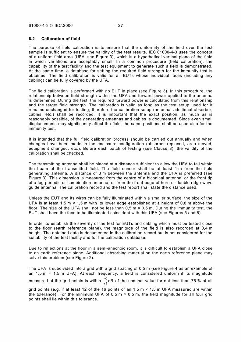
6.2 Calibration of field
The purpose of field calibration is to ensure that the uniformity of the field over the test sample is sufficient to ensure the validity of the test results. IEC 61000-4-3 uses the concept of a uniform field area (UFA, see Figure 3), which is a hypothetical vertical plane of the field in which variations are acceptably small. In a common procedure (field calibration), the capability of the test facility and the test equipment to generate such a field is demonstrated. At the same time, a database for setting the required field strength for the immunity test is obtained. The field calibration is valid for all EUTs whose individual faces (including any cabling) can be fully covered by the UFA.
The field calibration is performed with no EUT in place (see Figure 3). In this procedure, the relationship between field strength within the UFA and forward power applied to the antenna is determined. During the test, the required forward power is calculated from this relationship and the target field strength. The calibration is valid as long as the test setup used for it remains unchanged for testing, therefore the calibration setup (antenna, additional absorber, cables, etc.) shall be recorded. It is important that the exact position, as much as is reasonably possible, of the generating antennas and cables is documented. Since even small displacements may significantly affect the field, the same positions shall be used also for the immunity test.
It is intended that the full field calibration process should be carried out annually and when changes have been made in the enclosure configuration (absorber replaced, area moved, equipment changed, etc.). Before each batch of testing (see Clause 8), the validity of the calibration shall be checked.
The transmitting antenna shall be placed at a distance sufficient to allow the UFA to fall within the beam of the transmitted field. The field sensor shall be at least 1 m from the field generating antenna. A distance of 3 m between the antenna and the UFA is preferred (see Figure 3). This dimension is measured from the centre of a biconical antenna, or the front tip of a log periodic or combination antenna, or from the front edge of horn or double ridge wave guide antenna. The calibration record and the test report shall state the distance used.
Unless the EUT and its wires can be fully illuminated within a smaller surface, the size of the UFA is at least 1,5 m × 1,5 m with its lower edge established at a height of 0,8 m above the floor. The size of the UFA shall not be less than 0,5 m × 0,5 m. During the immunity test, the EUT shall have the face to be illuminated coincident with this UFA (see Figures 5 and 6).
In order to establish the severity of the test for EUTs and cabling which must be tested close to the floor (earth reference plane), the magnitude of the field is also recorded at 0,4 m height. The obtained data is documented in the calibration record but is not considered for the suitability of the test facility and for the calibration database.
Due to reflections at the floor in a semi-anechoic room, it is difficult to establish a UFA close to an earth reference plane. Additional absorbing material on the earth reference plane may solve this problem (see Figure 2).
The UFA is subdivided into a grid with a grid spacing of 0,5 m (see Figure 4 as an example of an 1,5 m × 1,5 m UFA). At each frequency, a field is considered uniform if its magnitude
measured at the grid points is within dB60
+− of the nominal value for not less than 75 % of all
grid points (e.g. if at least 12 of the 16 points of an 1,5 m × 1,5 m UFA measured are within the tolerance). For the minimum UFA of 0,5 m × 0,5 m, the field magnitude for all four grid points shall lie within this tolerance.

61000-4-3 IEC:2006 – 29 –
NOTE 1 At different frequencies, different measuring points may be within the tolerance.
The tolerance has been expressed as dB60
+− to ensure that the field strength does not fall
below nominal with an acceptable probability. The tolerance of 6 dB is considered to be the minimum achievable in practical test facilities.
In the frequency range up to 1 GHz, a tolerance greater than +6 dB, up to +10 dB, but not less than -0 dB is allowed for a maximum of 3 % of the test frequencies, provided that the
actual tolerance is stated in the test report. In case of dispute, the dB60
+− tolerance takes
precedence.
If the area intended to be occupied by the face of the actual EUT is larger than 1,5 m × 1,5 m and an UFA with sufficient dimensions (preferred method) can not be realised, then the area to be occupied by the EUT may be illuminated in a series of tests (“partial illumination”). Either:
– a calibration shall be performed at different radiating antenna locations so that the combined UFAs cover the area which will be occupied by the face of the EUT, and the EUT shall then be tested with the antenna in each of these positions successively,
– or the EUT shall be moved to different positions so that each part of it falls within the UFA during at least one of these tests.
NOTE 2 Each of the antenna positions requires a full field calibration.
Table 2 below demonstrates the concepts of full illumination and partial illumination as well as where and how they can be applied.
Table 2 – Requirements for uniform field area for application of full illumination, partial illumination and independent windows method
Frequency range Requirements of UFA size and calibration when the EUT fits completely within UFA (Full
Illumination, the preferred method)
Requirements of UFA size and calibration when the EUT does not fit completely within UFA (Partial Illumination and
Independent Windows, the alternative methods)
Less than 1 GHz Minimum UFA size 0,5 m × 0,5 m
UFA size in 0,5 m grid size steps (e.g., 0,5 m × 0,5 m; 0,5 m × 1,0 m; 1,0 m × 1,0 m; etc)
Calibration in 0,5 m × 0,5 m grid steps
75 % of calibration points within specifications if UFA is larger than 0,5 m × 0,5 m. 100 % (all 4 points) must be in specifications for 0,5 m × 0,5 m UFA.
PARTIAL ILLUMINATION
Minimum UFA size 1,5 m × 1,5 m
UFA size in 0,5 m grid size steps (e.g., 1,5 m × 1,5 m; 1,5 m × 2,0 m; 2,0 m × 2,0 m; etc)
Calibration in 0,5 m × 0,5 m grid steps
75 % of calibration points within specifications

61000-4-3 IEC:2006 – 31 –
Table 2 (continued)
Frequency range Requirements of UFA size and calibration when the EUT fits completely within UFA (Full
Illumination, the preferred method)
Requirements of UFA size and calibration when the EUT does not fit completely within UFA (Partial Illumination and
Independent Windows, the alternative methods)
Greater than 1 GHz Minimum UFA size 0,5 m × 0,5 m
UFA size in 0,5 m grid size steps (e.g., 0,5 m × 0,5 m; 0,5 m × 1,0 m; 1,0 m × 1,0 m; etc)
Calibration in 0,5 m × 0,5 m grid steps
75 % of calibration points within specifications if UFA is larger than 0,5 m × 0,5 m. 100 % (all 4 points) must be in specifications for 0,5 m × 0,5 m UFA.
INDEPENDENT WINDOWS METHOD
0,5 m × 0,5 m window (See Annex H)
PARTIAL ILLUMINATION
1,5 m × 1,5 m and larger size windows in 0,5 m increments (e.g., 1,5 m × 2,0 m; 2,0 m × 2,0 m; etc)
Calibration in 0,5 m × 0,5 m grid steps
75 % of calibration points within specifications if UFA is larger than 0,5 m × 0,5 m. 100 % (all 4 points) must be in specifications for 0,5 m × 0,5 m UFA.
If the requirements of this subclause can only be satisfied up to a certain limiting frequency (higher than 1 GHz), for example because the beam width of the antenna is insufficient to illuminate the entire EUT, then for frequencies higher than this, a second alternative method (known as “the independent window method”), described in Annex H, may be used.
Generally the calibration of the field in anechoic and semi-anechoic chambers has to be performed using the test setup shown in Figure 7. The calibration shall always be performed with an unmodulated carrier for both horizontal and vertical polarisations in accordance with the steps given below. It is required to ensure that the amplifiers can handle the modulation and are not saturated during testing. The preferred method to ensure the amplifiers are not saturated during testing is to carry out the calibration with a field strength at least 1,8 times as high as the field strength to be applied to the EUT. Denote this calibration field strength by Ec. Ec is the value which is applicable only to field calibration. The test field strength Et shall not exceed Ec /1,8.
NOTE 3 Other methods to ensure avoiding saturation may be used.
Two different calibration methods are described below using an 1,5 m × 1,5 m UFA (16 grid points) as an example. These methods are considered to give the same field uniformity.
6.2.1 Constant field strength calibration method
The constant field strength of the uniform field shall be established and measured via a calibrated field sensor at each particular frequency and at each of the 16 points one after the other (see Figure 4) using the step size given in Clause 8, by adjusting the forward power accordingly.
The forward power necessary to establish the field strength chosen shall be measured in accordance with Figure 7 and is to be recorded in dBm for the 16 points.

61000-4-3 IEC:2006 – 33 –
Procedure to be followed at both horizontal and vertical polarisations:
a) Position the sensor at one of the 16 points in the grid (see Figure 4), and set the frequency of the signal generator output to the lowest frequency in the range of the test (for example 80 MHz).
b) Adjust the forward power to the field-generating antenna so that the field strength obtained is equal to the required calibration field strength Ec. Record the forward power reading.
c) Increase the frequency by a maximum of 1 % of the present frequency. d) Repeat steps b) and c) until the next frequency in the sequence would exceed the highest
frequency in the range of the test. Finally, repeat step b) at this highest frequency (for example 1 GHz).
e) Repeat steps a) to d) for each point in the grid. At each frequency: f) Sort the 16 forward power readings into ascending order. g) Start at the highest value and check if at least the 11 readings below this value are within
the tolerance of –6 dB to +0 dB of that value. h) If they are not within this tolerance of –6 dB to +0 dB, go back to the same procedure,
starting by the reading immediately below and so on (notice that there are only five possibilities for each frequency).
i) Stop the procedure if at least 12 numbers are within 6 dB and record the maximum forward power out of the numbers. Denote this forward power by Pc;
j) Confirm that the test system (e.g. the power amplifier) is not in saturation. Assuming that Ec has been chosen as 1,8 times Et, perform the following procedure at each calibration frequency: j-1) Decrease the output from the signal generator by 5,1 dB from the level needed to
establish a forward power of Pc, as determined in the above steps. (-5,1 dB is the same as Ec /1,8.);
j-2) Record the new forward power delivered to the antenna; j-3) Subtract the forward power measured in step j-2 from Pc. If the difference is
between 3,1 and 5,1 dB, then the amplifier is not saturated and the test system sufficient for testing. If the difference is less than 3,1 dB, then the amplifier is saturated and is not suitable for testing.
NOTE 1 If at a specific frequency, the ratio between Ec and Et is R(dB), where R = 20 log(Ec/Et), then the test power Pt = Pc – R(dB). The subscripts c and t refer to calibration and test respectively. The field is modulated in accordance with Clause 8.
A description of an example for the calibration is given in D.4.1.
NOTE 2 At each frequency it has to be ensured that the amplifier used is not saturated. This can best be done by checking the 1 dB compression of the amplifier. However, the 1 dB compression of the amplifier is verified with a 50 Ω termination when the impedance of an antenna to be used for the test is different from 50 Ω. The saturation of the test system is assured by confirming the 2 dB compression point described to step j). For more information refer to the Annex D.
6.2.2 Constant power calibration method
The field strength of the uniform field shall be established and measured via a calibrated field sensor at each particular frequency and at each of the 16 points one after the other (see Figure 4) using the step size given in Clause 8, by adjusting the forward power accordingly.

61000-4-3 IEC:2006 – 35 –
The forward power necessary to establish the field strength at the starting position shall be measured in accordance with Figure 7 and noted. The same forward power shall be applied for all 16 positions. The field strength created by this forward power is to be recorded at each of the 16 points.
Procedure to be followed at both horizontal and vertical polarisations:
a) Position the sensor at one of the 16 points in the grid (see Figure 4), and set the frequency of the signal generator output to the lowest frequency in the range of the test (for example 80 MHz).
b) Apply a forward power to the field-generating antenna so that the field strength obtained equals Ec (taking into account that the test field will be modulated). Record the forward power and field strength readings.
c) Increase the frequency by a maximum of 1% of the present frequency. d) Repeat steps b) and c) until the next frequency in the sequence would exceed the highest
frequency in the range of the test. Finally, repeat step b) at this highest frequency (for example 1 GHz).
e) Move the sensor to another position in the grid. At each of the frequencies and used in steps a) to d), apply the forward power recorded in step b) for that frequency, and record the field strength reading.
f) Repeat step e) for each point in the grid. At each frequency : g) Sort the 16 field strength readings into ascending order. h) Select one field strength as the reference and calculate the deviation from this reference
for all other positions in decibels. i) Start at the lowest value of the field strength and check if at least 11 readings above this
value are within the tolerance of dB60
+− of that lowest value.
j) If they are not within the tolerance of dB60
+− , go back to the same procedure, starting by
the reading immediately above and so on (notice that there are only five possibilities for each frequency).
k) Stop the procedure if at least 12 numbers are within 6 dB and take from these numbers the position where the minimum field strength was obtained as the reference.
l) Calculate the forward power necessary to create the required field strength in the reference position. Denote this forward power by Pc.
m) Confirm that the test system (e. g. the power amplifier) is not in saturation. Assuming that Ec has been chosen as 1,8 times Et, perform the following procedure at each calibration frequency: m-1) Decrease the output from the signal generator by 5,1 dB from the level needed to
establish a forward power of Pc, as determined in the above steps. (-5,1 dB is the same as Ec /1,8.)
m-2) Record the new forward power delivered to the antenna. m-3) Subtract the forward power measured in step m-2 from Pc. If the difference is
between 3,1 dB and 5,1 dB, then the amplifier is not saturated and the test system is sufficient for testing. If the difference is less than 3,1 dB, then the amplifier is saturated and is not suitable for testing.
NOTE 1 If at a specific frequency, the ratio between Ec and Et is R(dB), where R = 20 log(Ec/Et), then the test power Pt = Pc – R(dB). The subscripts c and t refer to calibration and test respectively. The field is modulated in accordance with Clause 8.

61000-4-3 IEC:2006 – 37 –
A description of an example for the calibration is given in D.4.2.
NOTE 2 At each frequency it has to be ensured that the amplifier used is not saturated. This can best be done by checking the 1 dB compression of the amplifier. However, the 1 dB compression of the amplifier is verified with a 50 Ω termination when the impedance of an antenna to be used for the test is different from 50 Ω. The saturation of the test system is assured by confirming the 2 dB compression point described to step m). For more information refer to the Annex D.
7 Test setup
All testing of equipment shall be performed in a configuration as close as possible to actual installation conditions. Wiring shall be consistent with the manufacturer's recommended procedures, and the equipment shall be in its housing with all covers and access panels in place, unless otherwise stated.
If the equipment is designed to be mounted in a panel, rack or cabinet, it shall be tested in this configuration.
A metallic ground plane is not required. When a means is required to support the test sample, it shall be constructed of a non-metallic, non-conductive material. Low dielectric constant (low permittivity) materials, such as rigid polystyrene, should be considered. However, grounding of housing or case of the equipment shall be consistent with the manufacturer's installation recommendations.
When an EUT consists of floor-standing and table-top components, the correct relative positions shall be maintained.
Typical EUT setups are shown in Figures 5 and 6.
NOTE 1 Non-conductive supports are used to prevent accidental earthing of the EUT and distortion of the field. To ensure the latter, the support should be bulk non-conductive, rather than an insulating coating on a metallic structure.
NOTE 2 At higher frequencies (e.g., above 1 GHz), tables or supports made from wood or glass reinforced plastic can be reflective. So, a low dielectric constant (low permittivity) material, such as rigid polystyrene, should be used to avoid field perturbations and to reduce degradation of field uniformity.
7.1 Arrangement of table-top equipment
The equipment to be tested is placed in the test facility on a non-conductive table 0,8 m high.
The equipment is then connected to power and signal wires according to relevant installation instructions.
7.2 Arrangement of floor-standing equipment
Floor-standing equipment should be mounted on a non-conductive support 0,05 m to 0,15 m above the supporting plane. The use of non-conductive supports prevents accidental earthing of the EUT and distortion of the field. To ensure the latter, the support shall be bulk non-conducting, rather than an insulating coating on a metallic structure. Floor-standing equipment which is capable of being stood on a non-conductive 0,8 m high platform, i.e. equipment which is not too large or heavy, or where its elevation would not create a safety hazard, may be so arranged. This variation in the standard method of test shall be recorded in the test report.
NOTE Non-conductive rollers may be used as the 0,05 m to 0,15 m support.
The equipment is then connected to power and signal wires according to relevant installation instructions.

61000-4-3 IEC:2006 – 39 –
7.3 Arrangement of wiring
Cables shall be attached to the EUT and arranged on the test site according to the manufacturer’s installation instructions and shall replicate typical installations and use as much as possible.
The manufacturer’s specified wiring types and connectors shall be used. If the wiring to and from the EUT is not specified, unshielded parallel conductors shall be used.
If the manufacturer's specification requires a wiring length of less than or equal to 3 m, then the specified length shall be used. If the length specified is greater than 3 m or is not specified, then the length of cable used shall be chosen according to typical installation practices. If possible, a minimum of 1 m of cable is exposed to the electromagnetic field. Excess length of cables interconnecting units of the EUT shall be bundled low-inductively in the approximate center of the cable to form a bundle 30 cm to 40 cm in length.
If a product committee determines excess cable length needs to be decoupled (for example, for cables leaving the test area), then the decoupling method used shall not impair the operation of the EUT.
7.4 Arrangement of human body-mounted equipment
Human body-mounted equipment (see Definition 3.13) may be tested in the same manner as table top items. However, this may involve over-testing or under-testing because the characteristics of the human body are not taken into account. For this reason, product committees are encouraged to specify the use of a human body simulator with appropriate dielectric characteristics.
8 Test procedure
The test procedure includes:
– the verification of the laboratory reference conditions; – the preliminary verification of the correct operation of the equipment; – the execution of the test; – the evaluation of the test results.
8.1 Laboratory reference conditions
In order to minimize the effect of environmental parameters on test results, the test shall be carried out in climatic and electromagnetic reference conditions as specified in 8.1.1 and 8.1.2.
8.1.1 Climatic conditions
Unless otherwise specified by the committee responsible for the generic or product standard, the climatic conditions in the laboratory shall be within any limits specified for the operation of the EUT and the test equipment by their respective manufacturers.
Tests shall not be performed if the relative humidity is so high as to cause condensation on the EUT or the test equipment.
NOTE Where it is considered that there is sufficient evidence to demonstrate that the effects of the phenomenon covered by this standard are influenced by climatic conditions, this should be brought to the attention of the committee responsible for this standard.

61000-4-3 IEC:2006 – 41 –
8.1.2 Electromagnetic conditions
The electromagnetic conditions of the laboratory shall be such to guarantee the correct operation of the EUT in order not to influence the test results.
8.2 Execution of the test
The test shall be carried out on the basis of a test plan that shall include the verification of the performances of the EUT as defined in the technical specification.
The EUT shall be tested in normal operating conditions.
The test plan shall specify:
– the size of the EUT; – representative operating conditions of the EUT; – whether the EUT shall be tested as table-top or floor-standing, or a combination of the
two; – for floor-standing equipment, the height of the support; – the type of test facility to be used and the position of the radiating antennas; – the type of antennas to be used; – the frequency range, dwell time and frequency steps; – the size and shape of the uniform field area; – whether any partial illumination is used; – the test level to be applied; – the type(s) and number of interconnecting wires used and the interface port (of the EUT)
to which these are to be connected; – the performance criteria which are acceptable; – a description of the method used to exercise the EUT.
The test procedures described in this clause are for the use of field generating antennas as defined in Clause 6.
Before testing the intensity of the calibrated field strength should be checked to verify that the test equipment/system is operating properly.
After the calibration has been verified, the test field can be generated using the values obtained from the calibration (see 6.2).
The EUT is initially placed with one face coincident with the calibration plane. The EUT face being illuminated shall be contained within the UFA unless partial illumination is being applied. See Clause 6.2 regarding field calibration and use of partial illumination.
The frequency ranges to be considered are swept with the signal modulated according to 5.1 and 5.2, pausing to adjust the RF signal level or to switch oscillators and antennas as necessary. Where the frequency range is swept incrementally, the step size shall not exceed 1 % of the preceding frequency value.
The dwell time of the amplitude modulated carrier at each frequency shall not be less than the time necessary for the EUT to be exercised and to respond, but shall in no case be less than 0,5 s. The sensitive frequencies (e.g., clock frequencies) shall be analyzed separately according to the requirements in product standards.

61000-4-3 IEC:2006 – 43 –
The test shall normally be performed with the generating antenna facing each side of the EUT. When equipment can be used in different orientations (i.e. vertical or horizontal) all sides shall be exposed to the field during the test. When technically justified, some EUTs can be tested by exposing fewer faces to the generating antenna. In other cases, as determined for example by the type and size of EUT or the frequencies of test, more than four azimuths may need to be exposed.
NOTE 1 As the electrical size of the EUT increases, the complexity of its antenna pattern also increases. The antenna pattern complexity can affect the number of test orientations necessary to determine minimum immunity.
NOTE 2 If an EUT consists of several components, it is not necessary to modify the position of each component within the EUT while illuminating it from different sides.
The polarization of the field generated by each antenna necessitates testing each selected side twice, once with the antenna positioned vertically and again with the antenna positioned horizontally.
Attempts shall be made to fully exercise the EUT during testing, and to interrogate all the critical exercise modes selected for the immunity test. The use of special exercising programmes is recommended.
9 Evaluation of test results
The test results shall be classified in terms of the loss of function or degradation of performance of the equipment under test, relative to a performance level defined by its manu-facturer or the requestor of the test, or agreed between the manufacturer and the purchaser of the product. The recommended classification is as follows:
a) normal performance within limits specified by the manufacturer, requestor or purchaser; b) temporary loss of function or degradation of performance which ceases after the
disturbance ceases, and from which the equipment under test recovers its normal performance, without operator intervention;
c) temporary loss of function or degradation of performance, the correction of which requires operator intervention;
d) loss of function or degradation of performance which is not recoverable, owing to damage to hardware or software, or loss of data.
The manufacturer’s specification may define effects on the EUT which may be considered insignificant, and therefore acceptable.
This classification may be used as a guide in formulating performance criteria, by committees responsible for generic, product and product-family standards, or as a framework for the agreement on performance criteria between the manufacturer and the purchaser, for example where no suitable generic, product or product-family standard exists.
10 Test report
The test report shall contain all the information necessary to reproduce the test. In particular, the following shall be recorded:
– the items specified in the test plan required by Clause 8 of this standard; – identification of the EUT and any associated equipment, for example, brand name, product
type, serial number;

61000-4-3 IEC:2006 – 45 –
– identification of the test equipment, for example, brand name, product type, serial number; – any special environmental conditions in which the test was performed; – any specific conditions necessary to enable the test to be performed; – performance level defined by the manufacturer, requestor or purchaser; – performance criterion specified in the generic, product or product-family standard; – any effects on the EUT observed during or after the application of the test disturbance,
and the duration for which these effects persist; – the rationale for the pass/fail decision (based on the performance criterion specified in the
generic, product or product-family standard, or agreed between the manufacturer and the purchaser);
– any specific conditions of use, for example cable length or type, shielding or grounding, or EUT operating conditions, which are required to achieve compliance;
– a complete description of the cabling and equipment position and orientation shall be included in the test report; in some cases a picture may be sufficient for that.

61000-4-3 IEC:2006 – 47 –
3
2
1
0
–1
–2
–3
3
2
1
0
–1
–2
–3
Vp-p
Vrms
Vrms
Vmaximum rms
Vp-p
a) Unmodulated RF-signal Vp-p = 2,8 V Vrms = 1,0 V
b) Modulated RF-signal 80 % AM Vp-p = 5,1 V Vrms = 1,15 V Vmaximum rms = 1,8 V
IEC 029/06
Figure 1 – Definition of the test level and the waveshapes occurring at the output of the signal generator

61000-4-3 IEC:2006 – 49 –
Field generation antenna
Incoming mains power filter
0,8 m high non-conductive support Uniform
field area
Optional anechoic material in case of semi-anechoic chamber to reduce ground reflection
3 m
Interconnectingcables
Chamber penetration cables Field generation
equipment
EUT measurement instrumentation
Interconnection filter
0,8 m
IEC 030/06
NOTE Anechoic lining material on walls and ceiling has been omitted for clarity.
Figure 2 – Example of suitable test facility

61000-4-3 IEC:2006 – 51 –
Field generation antenna
Optional anechoic material in case of semi-anechoic chamber to reduce floor reflections
Isotropic field probe
Uniform field area
Chamber wall
0,8 m
3 m
Fibre optic or filtered signal link
IEC 031/06
Figure 3 – Calibration of field

61000-4-3 IEC:2006 – 53 –
Sensor positions (equally spaced)
0,5 m
1,5 m
0,5 m
0,8 m
1,5 mFloor
Uniform field area
IEC 032/06
Figure 4 – Calibration of field, dimensions of the uniform field area

61000-4-3 IEC:2006 – 55 –
Uniform field area
Non- conductingtable
0,8 m
Shielded power cable
Shielded connection through chamber wall
Chamber wall
Shielded signal cable Non-conducting
support
Optional anechoic material in case of semi-anechoic chamber to reduce floor reflections IEC 033/06
0,05 m to 0,15 m
NOTE Anechoic lining material has been omitted from walls for clarity.
Figure 5 – Example of test setup for floor-standing equipment

61000-4-3 IEC:2006 – 57 –
Uniform field area
Non-conducting table
Wiring <3 m bundled non-inductively to 1 m overall length
Wiring overall length <1 m as is
Wiring >3 m or not specified. Illuminated length shall be 1 m
Optional anechoic material in case of semi-anechoic chamber to reduce floor reflections
Field generating antenna
0,8 m
IEC 034/06
Figure 6 – Example of test setup for table-top equipment

61000-4-3 IEC:2006 – 59 –
Anechoic room
6 )
7 )
2 ) 3 )
1 )
4 )
5 )
8 )
Optional link
IEC 035/06
1 ) Controller, for example PC 2 ) Signal generator 3 ) Power amplifier 4 ) Directional coupler a
5 ) Measuring instrument a
6 ) Transmitting antenna 7 ) Field sensor 8 ) Field meter a The directional coupler and power meter may be replaced by a forward power detector or monitor inserted between amplifier 3) and antenna 6).
Figure 7 – Measuring set-up

61000-4-3 IEC:2006 – 61 –
Annex A (informative)
Rationale for the choice of modulation for tests related to the protection
against RF emissions from digital radio telephones
A.1 Summary of available modulation methods
The essential threat above 800 MHz comes from digital radio telephones using non-constant envelope modulation. During the development of this standard, the following modulation methods were considered for the electromagnetic field:
– sine wave amplitude modulation, 80 % AM at 1 kHz rate; – square wave amplitude modulation, 1:2 duty cycle, 100 % AM at 200 Hz rate; – pulsed RF signal approximately simulating the characteristics of each system, e.g. 1:8
duty cycle at 200 Hz for GSM, 1:24 duty cycle at 100 Hz for DECT portables, etc. (see Annex G for definitions of GSM and DECT);
– pulsed RF signal simulating exactly the characteristics of each system, e.g. for GSM: 1:8 duty cycle at 200 Hz plus secondary effects such as discontinuous transmission mode (2 Hz modulation frequency) and multi-frame effects (8 Hz frequency component).
The merits of the respective systems are summarised in Table A.1.

61000-4-3 IEC:2006 – 63 –
Table A.1 − Comparison of modulation methods
(see Annex G for definitions of GSM and DECT)
Modulation method
Advantages
Disadvantages
Sine wave AM 1 Experimentation has shown that good correlation may be established between the interfering effects of different types of non-constant envelope modulation provided the maximum RMS levels remains the same.
1 Does not simulate TDMA.
2 It is not necessary to specify (and measure) the rise time of the TDMA pulse.
2 Slight over-test for second law receptors.
3 Used in this standard and in IEC 61000-4-6. 3 May miss some failure mechanisms.
4 Field generation and monitoring equip-ment is readily available.
5 For analogue audio equipment, demodulation in the equipment under test produces an audio response which can be measured with a narrow band level meter, thereby reducing background noise.
6 Has already been shown to be effective at simulating the effects of other modulation types (e.g. FM, phase modulation, pulse modulation) at lower frequencies.
Square wave AM 1 Similar to TDMA. 1 Does not exactly simulate TDMA.
2 Can be applied universally. 2 Requires non-standard equipment to generate the signal.
3 May reveal "unknown" failure mechanisms (sensitive to the large rate of change of the RF envelope).
3 Demodulation in EUT produces a broad-band audio response which shall be measured with a broadband level meter, thereby raising background noise.
4 Necessary to specify the rise time.
Pulsed RF 1 Good simulation of TDMA. 1 Requires non-standard equipment to generate the signal.
2 May reveal "unknown" failure mechanisms (sensitive to the large rate of change of the RF envelope).
2 The details of the modulation need to be varied to match each of the different systems (e.g. GSM, DECT, etc.).
3 Demodulation in EUT produces a broad-band audio response which shall be measured with a broadband level meter, thereby raising background noise.
4 Necessary to specify the rise time.

61000-4-3 IEC:2006 – 65 –
A.2 Experimental results
A series of experiments has been performed to assess the correlation between the modulation method used for the disturbing signal and the interference produced.
The modulation methods investigated were as follows:
a) sine wave 80 % AM at 1 kHz; b) "GSM-like" pulsed RF, duty cycle 1:8 at 200 Hz; c) "DECT-like" pulsed RF, duty cycle 1:2 at 100 Hz (base station); d) "DECT-like" pulsed RF, duty cycle 1:24 at 100 Hz (portable).
Only one of the "DECT-like" modulations was used in each case.
The results are summarised in Tables A.2 and A.3.
Table A.2 − Relative interference levels a
Modulation method b
Sine wave 80 % AM at 1 kHz
"GSM-like" duty cycle 1:8
at 200 Hz
"DECT-like" duty cycle 1:24
at 100 Hz
↓ Equipment ↓ Audio response dB dB dB
Hearing aid c
Unweighted 21 Hz – 21 kHz
0 d
0 – 3
A-weighted 0 – 4 – 7
Analogue telephone set e
Unweighted 0 d
– 3 – 7
A-weighted – 1 – 6 – 8
Radio set f
Unweighted 0 d
+ 1 – 2
A-weighted – 1 – 3 – 7
a The audio response to the disturbance is the interference level. A low interference level means a high-immunity level. b Important: the carrier amplitude is adjusted so that the maximum RMS value (see Clause 3) of the disturbing signal (exposure) is the same for all modulations. c The exposure is produced by an incident electromagnetic field at 900 MHz. The duty cycle for the DECT-like modulation is 1:2 instead of 1:24. The audio response is the acoustical output measured with an artificial ear connected via a 0,5 m PVC tube. d This case is chosen as the reference audio response, i.e. 0 dB. e The exposure is an RF current injected into the telephone cable at 900 MHz. The audio response is the audio-frequency voltage measured on the telephone line. f The exposure is an RF current injected into the mains cable at 900 MHz. The audio response is the audio output from the loudspeaker measured with a microphone.

61000-4-3 IEC:2006 – 67 –
Table A.3 − Relative immunity levels a
Modulation method b
Sine wave 80 % AM at 1 kHz
"GSM-like" duty cycle 1:8
at 200 Hz
"DECT-like" duty cycle 1:24
at 100 Hz
↓ Equipment ↓ Response dB dB dB
TV set c
Noticeable interference 0 d
–2 –2
Strong interference +4 +1 +2
Screen off ~+19 +18 +19
Data terminal with RS232 interface e
Interference on the video screen
0 d
0 –
Data errors > +16 > +16 –
RS232 modem f
Data errors (injected on telephone interface)
0 d
0 0
Data errors (injected on RS232 interface)
> +9 > +9 > +9
Regulated laboratory supply g
2 % error in DC output current
0 d
+3 +7
SDH cross connect h Bit error threshold 0 d
0 –
a The numbers in the table are a relative measure of the maximum RMS level (see Clause 3) of the disturbing signal (exposure) necessary to produce the same degree of interference with all modulations. A high decibel level means high immunity. b The disturbing signal is adjusted so that the same response (interference) is produced with all modulations. c The exposure is an RF current injected into the mains cable at 900 MHz. The response is the degree of interference produced on the screen. The assessment is rather subjective as the interference patterns are different for the different cases. d This case is chosen as the reference immunity level, i.e. 0 dB. e The exposure is an RF current injected into the RS232 cable at 900 MHz. f The exposure is an RF current injected into either the telephone or the RS232 cable at 900 MHz. g The exposure is an RF current at 900 MHz injected into the d.c. output cable. h SDH = synchronous digital hierarchy. The exposure is an incident electromagnetic field at 935 MHz.
The following items of digital equipment were tested using both sine wave AM and pulse modulation (duty cycle 1:2) at field strengths of up to 30 V/m:
– hand dryer with microprocessor control; – 2 Mb modem with 75 Ω coaxial cable; – 2 Mb modem with 120 Ω twisted pair cable; – industrial controller with microprocessor, video display and RS485 interface; – train display system with microprocessor; – credit card terminal with modem output; – digital multiplexer 2/34 Mb; – Ethernet repeater (10 Mb/s).
All failures were associated with the analogue functions of the devices.

61000-4-3 IEC:2006 – 69 –
A.3 Secondary modulation effects
When trying to simulate exactly the modulation used in a digital radio telephone system, it is important not only to simulate the primary modulation but also to consider the impact of any secondary modulation which may be present.
For example, with GSM and DCS 1800, there are multi-frame effects caused by the suppression of a burst every 120 ms (thereby creating a frequency component at approximately 8 Hz). There may also be additional modulation at 2 Hz from the optional discontinuous transmission (DTX) mode.
A.4 Conclusion
It can be seen from the cases studied that the items tested responded to the disturbances independently of the modulation method used. When comparing the effects of different modulations, it is important to ensure that the same maximum RMS level of interfering signal is used.
Where significant differences existed between the effects of different modulation types, sine wave AM was always the most severe.
Where different responses are observed for sine wave modulation and TDMA, the product specific difference may be corrected by appropriate adjustment of the compliance criteria in the product standard.
In summary, sine wave modulation has the following advantages:
– narrow band detection response in analogue systems reducing background noise problems;
– universal applicability, i.e. no attempt to simulate the behaviour of the disturbing source;
– same modulation at all frequencies;
– always at least as severe as pulse modulation.
For the reasons stated above, the modulation method defined in this standard is 80 % AM sine wave. It is recommended that product committees change the modulation method only if there are specific reasons requiring a different type of modulation.

61000-4-3 IEC:2006 – 71 –
Annex B (informative)
Field generating antennas
B.1 Biconical antenna
This antenna consists of a coaxial balun and three-dimensional element which provide a broad frequency range and can be used both for transmitting and receiving. The antenna factor curve is a substantially smooth line, typically increasing with frequency.
The compact size of these antenna makes them ideal for use in restricted areas such as anechoic chambers as proximity effects are minimized.
B.2 Log-periodic antenna
A log-periodic antenna is an array of dipoles of different lengths connected to a transmission line.
These broadband antennas have a relatively high gain and low VSWR.
When choosing an antenna for the generation of fields, it should be established that the balun can handle the necessary power.
B.3 Horn antenna and double ridge wave guide antenna
Horn antennas and double ridge wave guide antennas produce linearly polarised electromagnetic fields. They are typically used at frequencies above 1 000 MHz.

61000-4-3 IEC:2006 – 73 –
Annex C (informative)
Use of anechoic chambers
C.1 General anechoic chamber information
A semi-anechoic chamber is a shielded enclosure having radio absorbing material on the walls and ceiling. Anechoic chambers also have such lining on the floor.
The purpose of this lining is to absorb the RF energy, preventing reflections back into the chamber. Such reflections, by interfering in a complex way with the directly radiated field, can produce maxima and minima in the intensity of the generated field.
The reflection loss of the absorbing material generally depends on the frequency of the incident wave and its angle to the normal. The loss (absorption) is typically greatest at normal incidence and decreases as the angle of incidence increases.
In order to break up reflections and enhance absorption, the absorbing material is often shaped into wedges or cones.
For semi-anechoic chambers, modification by the addition of extra RF absorbing material on the floor helps to achieve the required field uniformity at all frequencies. Experimentation will reveal the materials and positions for such additions.
The additional absorbing material should not be placed in the direct illumination path from the antenna to the EUT, but should be positioned in the identical location and orientation for testing as used during the calibration procedure.
Uniformity can also be improved by placing the field generating antenna off the axis of the chamber, such that any reflections are not symmetrical.
Anechoic chambers are less effective at low frequencies (below 30 MHz), whereas ferrite-lined chambers may also be less effective at frequencies above 1 GHz. Care shall be taken to ensure the uniformity of the generated field at the lowest and highest frequencies, and it may be necessary to rework the chamber.
C.2 Suggested adjustments to adapt for use at frequencies above 1 GHz ferrite-lined chambers designed for use at frequencies up to 1 GHz
Most of the existing small anechoic chambers which use ferrite as an absorber are designed for use at frequencies up to 1 GHz. At frequencies above 1 GHz, it may be difficult or impossible for such chambers to satisfy the field uniformity requirement of 6.2 of this standard.
This paragraph presents information on the procedures to adapt such chambers for testing at frequencies above 1 GHz using the method described in Annex H.

61000-4-3 IEC:2006 – 75 –
C.2.1 Problems caused by the use of ferrite-lined chambers for radiated field immunity tests at frequencies above 1 GHz
The problem described below may occur, for example, in a small ferrite-lined anechoic chamber, or in a small (typically 7 m (l) × 3 m (w) × 3 m (h)) anechoic chamber lined with a combination of ferrite and carbon-loaded absorbers.
At frequencies above 1 GHz, the ferrite tiles usually behave as reflectors rather than as absorbers. It is very difficult to establish a uniform field over a 1,5 m × 1,5 m area at these frequencies owing to multiple reflections from the inner surfaces of the chamber (see Figure C.1).
IEC 036/06
Figure C.1 − Multiple reflections in an existing small anechoic chamber
At the frequencies of the radio telephone bands, the wavelength is shorter than 0,2 m. This means that test results are very sensitive to the positioning of the field-generating antenna and the field sensor or EUT.
C.2.2 Possible solution
In order to solve existing problems, the following procedures are suggested.
a) Use a horn antenna or a double-ridge wave guide antenna to reduce the field radiated backwards. This also decreases reflections from the side walls of the chamber because of the narrow beam width of the antenna.
b) Shorten the distance between the transmitting antenna and EUT to minimize reflections from the side walls (the distance between the antenna and EUT can be reduced to 1 m). Use the method of 0,5 m × 0,5 m independent windows (Annex H) to ensure that the EUT is exposed to a uniform field.
c) Attach medium-loaded carbon type anechoic material to the rear wall facing the EUT to eliminate direct reflection. This reduces the sensitivity of the test to the positioning of the EUT and antenna. It also may improve field uniformity at frequencies below 1 GHz. NOTE If a highly-loaded carbon type anechoic material is used, it may be difficult to satisfy the requirement for field uniformity at frequencies below 1 GHz.
Following the above procedures will eliminate most of the reflected waves (see Figure C.2).

61000-4-3 IEC:2006 – 77 –
Antenna is positioned at each window.
IEC 037/06
Figure C.2 − Most of the reflected waves are eliminated

61000-4-3 IEC:2006 – 79 –
Annex D (informative)
Amplifier non-linearity and example for the calibration procedure
according to 6.2
D.1 Objective of limiting amplifier distortion
The goal is to keep amplifier non-linearity at a level low enough such that it does not dominate the uncertainty of the value of the field strength. Consequently, a guideline is given to assist test laboratories in understanding and limiting amplifier saturation effects.
D.2 Possible problems caused by harmonics and saturation
Overloading the amplifier may result in the following scenarios.
a) The harmonics may contribute significantly to the field. 1) If this occurs during calibration, the field strength at the intended frequency is
incorrectly measured, as the broadband field probe will measure the fundamental and its harmonics. For example, assume that the third harmonic is 15 dB below the fundamental frequency at the antenna terminal and all other harmonics can be ignored. Further assume that the effective antenna factor is 5 dB lower at the frequency of the third harmonic than at the fundamental frequency. The field strength of the fundamental frequency will be only 10 dB larger than the field strength of the third harmonic. If a total field strength of 10 V/m is measured, the fundamental frequency will contribute 9,5 V/m. This is an acceptable error, as it is smaller than the field probe amplitude uncertainty.
2) If harmonics are significantly present during a test, they may cause an EUT failure although the EUT is robust at the intended fundamental frequency but not robust at the harmonic frequency.
b) Harmonics may also affect the test result, even if they are very well suppressed in special situations. For example, if a 900 MHz receiver is tested, even very weak harmonics of a 300 MHz signal may overload the receiver input. A similar scenario may also occur if the signal generator outputs non-harmonically-related signals.
c) Saturation may be present without measurable harmonics. This occurs if the amplifier has a low pass output filter which suppresses the harmonics. This situation may also lead to incorrect results. 1) If this occurs during calibration, wrong calibration data will be derived as the
assumption of linearity is used in the algorithm described in 6.2. 2) During a test, this type of saturation will lead to an incorrect modulation index and
harmonics of the modulation frequency (usually 1 000 Hz).
From the examples given above, it is clear that a numerical limit for amplifier distortion can not be given, as the effect of distortion depends heavily on the type of EUT tested.

61000-4-3 IEC:2006 – 81 –
D.3 Options for controlling amplifier non-linearity
D.3.1 Limiting the harmonic content in the field
The harmonic content of the field can be limited with the use of an adjustable/tracking/tunable low-pass filter at the output of the amplifier.
For all frequencies where harmonics are produced at the output of the amplifier, the rejection of these harmonics in the field by more than 6 dB below the fundamental is adequate, with exception of the scenario discussed in D.2 b).
This would limit the field strength error to 10 %. For example, a 10 V/m signal measured broadband would be caused by 9 V/m from the fundamental and 4,5 V/m from the harmonics. This is a situation which is acceptable for calibration uncertainty.
For amplifiers containing a fixed low-pass filter in their output, the upper fundamental frequency concerned is about 1/3 of the maximum specified frequency of the amplifier.
D.3.2 Measuring the harmonic content of the field
The harmonic content of the field can be either be measured directly using a selective field probe or indirectly by
– determining first the effective antenna factor (the ratio between input power and field strength for a given chamber and antenna position) and then the ratio between the forward powers at the fundamental frequency and the harmonics or
– with a coupler by taking account of the antenna factor at the harmonics as provided by the antenna manufacturer.
For situations in which a low pass filter suppresses harmonics of a saturated amplifier it is suggested under no circumstances (for example worst frequency, maximum field strength with modulation) to exceed the 2 dB compression point of the amplifier. At the 2 dB compression point, the peak amplitude (in voltage) would be reduced by 20 %. This would cause a reduction of the 80 % modulation index down to 64 %, in other words, a 20 % reduction of a voltage rectified within the EUT.

61000-4-3 IEC:2006 – 83 –
D.4 Examples showing the equivalence of the two calibration methods
13 14 15 16
9 10 11 12
5 6 7 8
1 2 3 4
0,5 m
0,5 m
IEC 038/06
Figure D.1 − Measuring positions of the uniform field area
Figure D.1 shows the 16 positions where the field uniformity has to be measured. The distance between each of the 16 points has been fixed at 0,5 m.
D.4.1 Example for the calibration procedure using the constant field strength calibration method as described in 6.2.1
To create a constant field strength of Ec = 6 V/m (as an example) the following forward power values shown in Table D.1 have been measured at one particular frequency using the measuring setup according to Figure 7.

61000-4-3 IEC:2006 – 85 –
Table D.1 – Forward power values measured according to the constant
field strength calibration method
Table D.2 – Forward power values sorted according to rising value and evaluation of the measuring result
Position Forward power dBm
Position Forward power dBm
1 27 2 22
2 22 7 23
3 37 1 27
4 33 8 27
5 31 9 28
6 29 6 29
7 23 10 30
8 27 11 30
9 28 14 30
10 30 5 31
11 30 12 31
12 31 15 31
13 40 16 31
14 30 4 33
15 31 3 37
16 31 13 40
NOTE Position 13 : 40 - 6 = 34, only 2 positions comply. Position 3 : 37 – 6 = 31, only 6 positions comply. Position 4 : 33 – 6 = 27, 12 positions comply.
In this example the measuring points 2, 3, 7 and 13 lie outside the dB60
+− criterion but at least
(in this example) 12 out of 16 points are within the criterion. Thus, at this particular frequency, the criterion is fulfilled. In this case, the forward power to be applied is 33 dBm. This ensures that for the 12 points the field strength Ec is at least 6 V/m (position 4) and at most 12 V/m (positions 1 and 8).
D.4.2 Example for the calibration procedure using the constant power calibration method as described in 6.2.2
Point No. 1 has been chosen as a first calibration point, where a target field strength Ec of 6 V/m has been produced. At the same forward power, the following field strengths shown in Table D.3 have been recorded at one particular frequency using the measuring setup according to Figure 7.

61000-4-3 IEC:2006 – 87 –
Table D.3 – Forward power and field strength values measured according to the constant power calibration method
Table D.4 – Field strength values sorted according to rising value and evaluation
of the measuring result
Position Forward power
dBm
Field strength
V/m
Field strength
dB relative to position 1
Position Forward power
dBm
Field strength
V/m
Field strength
dB relative to position 1
1 27 6,0 0 13 27 1,3 –13
2 27 10,7 5 3 27 1,9 –10
3 27 1,9 –10 4 27 3,0 –6
4 27 3,0 –6 5 27 3,8 –4
5 27 3,8 –4 12 27 3,8 –4
6 27 4,8 –2 15 27 3,8 –4
7 27 9,5 4 16 27 3,8 –4
8 27 6,0 0 10 27 4,2 –3
9 27 5,3 –1 11 27 4,2 –3
10 27 4,2 –1 14 27 4,2 –3
11 27 4,2 –3 6 27 4,8 –2
12 27 3,8 –4 9 27 5,3 –1
13 27 1,3 –13 1 27 6,0 0
14 27 4,2 –3 8 27 6,0 0
15 27 3,8 –4 7 27 9,5 4
16 27 3,8 –4 2 27 10,7 5 NOTE
Position 13 : –13 + 6 = –7, only 2 positions comply. Position 3 : –10 + 6 = –4, only 6 positions comply. Position 4 : –6 + 6 = 0, 12 positions comply.
In this example the measuring points 13, 3, 7 and 2 lie outside the dB60
+− criterion but at least
(in this example exactly) 12 out of 16 points are within the criterion. Thus at this particular frequency the criterion is fulfilled. In this case the forward power to be applied for the field strength Ec = 6 V/m is 27 dBm + 20 log (6 V/m/3 V/m) = 33 dBm. This ensures that for the 12 points the field strength Ec is at least 6 V/m (position 4) but in maximum 12 V/m (positions 1 and 8).

61000-4-3 IEC:2006 – 89 –
Annex E (informative)
Guidance for product committees on the selection of test levels
E.1 Introduction
The transmitted power of radio transmitters is often specified in terms of ERP (effective radiated power) referred to a half-wave dipole. Therefore, the generated field strength, for the far field, can be directly obtained by the following dipole formula:
E = k P /d (Equation E.1)
where E is the field strength (RMS value) (V/m);
k is a constant, with a value of 7, for free-space propagation in the far field; P is the power (ERP) (W); d is the distance from the antenna (m).
Nearby reflecting and absorbing objects alter the field strength.
If the ERP of the transmitter is not known, the power provided to the antenna may be used in Equation E.1 instead. In this case, a value of k = 3 is typically applicable for mobile radio transmitters.
E.2 Test levels related to general purposes
The test levels and the frequency bands are selected in accordance with the electromagnetic radiation environment to which the EUT can be exposed when finally installed. The consequences of failure should be borne in mind in selecting the test level to be applied. A higher level should be considered if the consequences of failure are significant.
If the EUT is to be installed at only a few sites, then an inspection of local RF sources will enable a calculation of field strengths likely to be encountered. If the powers of the sources are not known, it may be possible to measure the actual field strengths at the location(s) concerned.
For equipment intended for operation in a variety of locations, the following guidance may be used in selecting the test level to be applied.
The following classes are related to the levels listed in Clause 5; they are considered as general guidelines for the selection of the corresponding levels.
− Class 1: Low-level electromagnetic radiation environment. Levels typical of local radio/television stations located at more than 1 km, and transmitters/receivers of low power.

61000-4-3 IEC:2006 – 91 –
− Class 2: Moderate electromagnetic radiation environment. Low power portable transceivers (typically less than 1 W rating) are in use, but with restrictions on use in close proximity to the equipment. A typical commercial environment.
− Class 3: Severe electromagnetic radiation environment. Portable transceivers (2 W rating or more) are in use relatively close to the equipment but not less than 1 m. High power broadcast transmitters are in close proximity to the equipment and ISM equipment may be located close by. A typical industrial environment.
− Class 4: Portable transceivers are in use within less than 1 m of the equipment. Other sources of significant interference may be within 1 m of the equipment.
− Class x: x is an open level which might be negotiated and specified in the product standard or equipment specification.
E.3 Test levels related to the protection against RF emissions from digital radio telephones
The test levels should be selected in accordance with the expected electromagnetic field, i.e. considering the power of the radio telephone equipment and the likely distance between its transmitting antenna and the equipment to be tested. Usually, mobile stations will give rise to more severe requirements than base stations (because mobiles tend to be located much closer to potentially susceptible devices than base stations).
The cost for establishing the required immunity and the consequences of failure should be borne in mind when selecting the test level to be applied. A higher level should only be con-sidered if the consequences of failure are large.
Higher exposures than the selected test level may occur in practice with a lower rate of occurrence. In order to prevent unacceptable failures in those situations, it may be necessary to perform a second test at a higher level and accept a reduced performance (i.e. defined degradation accepted).
Table E.1 gives examples of test levels, performance criteria and the associated protection distances. The protection distance is the minimum acceptable distance to a digital radio telephone, when testing has been performed at the stated test level. These distances are calculated from Equation E.1, using k = 7 and assuming testing is carried out with an 80 % sinusoidal AM.

61000-4-3 IEC:2006 – 93 –
Table E.1 – Examples of test levels, associated protection distances and suggested performance criteria
Test level
Carrier field
strength
Maximum RMS field strength
Protection distance for
Performance
criteria a
V/m
V/m
2W GSM m
8W GSM m
¼W DECTm
Example 1 b
Example 2 c
1 1 1,8 5,5 11 1,9 – –
2 3 5,4 1,8 3,7 0,6 a –
3 10 18 0,6 1,1 ~ 0,2 d b a
4 30 54 ~ 0,2 d 0,4 ~ 0,1 d – b
a According to Clause 9. b Equipment for which the consequences of failure are not severe. c Equipment for which the consequences of failure are severe. d At these and closer distances, the far field Equation E.1 is not accurate.
The following issues were considered when formulating the above table:
– for GSM, most terminals on the market today are of class 4 (maximum ERP 2 W). A substantial number of mobile terminals in operation are classes 3 and 2 (maximum ERP 5 W and 8 W, respectively). The ERP of GSM terminals is often lower than maximum except in areas of poor reception;
– the coverage indoors is worse than outdoors, which implies that the ERP indoors may more often than not adjust to the maximum of the class. This is the worst case situation from an EMC point of view since most of the victim equipment is also concentrated indoors;
– as described in Annex A, the immunity level of an item of equipment is well correlated with the maximum RMS value of the modulated field. For that reason, the maximum RMS field strength has been inserted into Equation E.1 instead of the carrier field strength to calculate the protection distance;
– the estimated minimum distance for safe operation, also called protection distance, has been calculated with k = 7 in Equation E.1 and does not take into account the statistical fluctuations of the field strength, due to reflections from walls, floor and ceiling, which are on the order of ±6 dB;
– the protection distance according to Equation E.1 depends on the effective radiated power of the digital radio telephone and not on its operating frequency.
E.4 Special measures for fixed transmitters
The levels derived from the information in this Annex are typical values which are rarely exceeded in the described locations. At some locations these values will be exceeded e.g. radar installations, the proximity of high-power transmitters or ISM equipment located in the same building. In such cases, it may be preferable to shield the room or building and filter the signal and power wires to the equipment, rather than specify all equipment to be immune to such levels.

61000-4-3 IEC:2006 – 95 –
Annex F (informative)
Selection of test methods
This standard and IEC 61000-4-6 define two methods for testing the immunity of electrical and electronic equipment against radiated electromagnetic energy.
In general, tests with conducted signals are more useful at lower frequencies, and tests with radiated signals more useful at higher frequencies.
There is a range of frequencies for which the test methods which appear in either standard are useable. It is possible to use the test method defined in IEC 61000-4-6 up to 230 MHz. It is also possible to use the test method defined in this part down to 26 MHz. The purpose of this annex is to provide a guide to product committees and product specification writers in the selection of the most appropriate test method to ensure repeatability, based on the design and type of EUT.
Consideration should be given to:
– the wavelength of the radiated field compared to the mechanical dimensions of the EUT; – the relative dimensions of the cabinets and wires of the EUT; – the number of wires and enclosures which constitute the EUT.

61000-4-3 IEC:2006 – 97 –
Annex G (informative)
Description of the environment
G.1 Digital radio telephones
Tables G.1, G.2 and G.3 list radio system parameters relevant to EMC.
The abbreviations and definitions listed hereafter are used in the aforementioned tables:
– CDMA (Code Division Multiple Access): multiplexing where the transmitter encodes the signal using a pseudo-random sequence which the receiver also knows and can use to decode the received signal. Each different random sequence corresponds to a different communication channel;
– CT-2 (Cordless Telephone, second generation): cordless telephone system, widely used in some European countries;
– DCS 1800 (Digital Cellular System): cellular mobile telecommunication system, low cost, worldwide use;
– DECT (Digital Enhanced Cordless Telecommunications): cordless cellular telecom-munication system, low cost, widely used in Europe;
– DTX (Discontinuous Transmission): significantly reduced burst repetition frequency, used for power saving, when no information needs to be transmitted;
– ERP (Effective Radiated Power): effective radiated power referred to a half-wave dipole; – FDD (Frequency Division Duplex): multiplexing in which different frequencies are allocated to
the transmit and receive channels; – FDMA (Frequency Division Multiple Access): multiplexing in which separate frequency
bands are allocated to each channel; – GSM (Global System for Mobile Communications): cellular mobile telecommunication
system, worldwide use; – HIPERLAN: High performance radio local area network; – IMT-2000 (International Mobile Telecommunication 2000): 3rd generation cellular phone
technology which according to the size and speed of transmissions, allow users to receive high quality colour video images;
– NADC (North American Digital Cellular): digital cellular mobile communication system, widely used in North America. A popular term used to describe digital cellular systems that comply with Telecommunications Industry Association Interim Standard – 54; also known as D-AMPS;
– PDC (Personal Digital Cellular System): cellular mobile telecommunication system, widely used in Japan;
– PHS (Personal Handy Phone System): cordless telephone system, widely used in Japan; – RFID (Radio Frequency Identification): RFID systems include automatic article
identification, asset tracking, alarm systems, personnel identification, access control, proximity sensors;

61000-4-3 IEC:2006 – 99 –
– RTTT (Road Traffic & Transport Telematics): includes road toll systems. – TDMA (Time Division Multiple Access): see Clause 4; – TDD (Time Division Duplex): multiplexing in which different time slots are allocated to
the transmit and receive channels.

61000-4-3 IE
C:2006 – 101 –
Table G.1 – Mobile and portable units
System name
Parameters
GSM DCS 1800 DECT CT-2 PDC PHS NADC IMT-2000 TDD
IMT-2000 FDD
Transmitter frequency range
890 MHz to
915 MHz
1,71 GHz to1,784 GHz
1,88 GHz to
1,96 GHz
864 MHz to868 MHz
940 MHz to 956 MHz and
1,429 GHz to
1,453 GHz
1,895 GHz to
1,918 GHz
825 MHz to
845 MHz
1 900 MHz to
1 920 MHz
1 920 MHz to
1 980 MHz
Access Technique TDMA TDMA TDMA/ TDD
FDMA/ TDD
TDMA TDMA/ TDD
TDMA CDMA/ TDMA TDD
CDMA/ FDMA FDD
Burst repetition frequency
217 Hz 217 Hz 100 Hz 500 Hz 50 Hz 200 Hz 50 Hz NA NA
Duty cycle 1:8 1:8 1:24 (also 1:48 and
1:12)
1:12 1:3 1:8 1:3 Continuous Continuous
Maximum ERP 0,8 W; 2 W; 5 W;
8 W; 20 W
0,25 W; 1 W; 4 W
0,25 W <10 mW 0,8 W; 2 W
10 mW <6 W 0,25 W 0,25 W
Secondary modulation
2 Hz (DTX) and 0,16 Hz to
8,3 Hz (multi-frame)
2 Hz (DTX) and
0,16 Hz to 8,3 Hz (multi-frame)
None None None None None None None
Geographical area Worldwide Worldwide Europe Europe Japan Japan USA Europe Europe
NOTE CT-3 is considered to be covered by DECT.

61000-4-3 IE
C:2006 – 103 –
Table G.2 – Base stations
System name Parameters GSM DCS 1800 DECT CT-2 PDC PHS NADC IMT-2000
TDD IMT-2000
FDD
Transmitter frequency range
935 MHz to
960 MHz
1,805 GHz to
1,88 GHz
1,88 GHz to
1,96 GHz
864 MHz to868 MHz
810 MHz to 826 MHz and 1,477 GHz to
1,501 GHz
1,895 GHz to
1,918 GHz
870 MHz to
890 MHz
1 900 MHz to
1 920 MHz
2 110 MHz to
2 170 MHz
Access Technique TDMA TDMA TDMA/ TDD
FDMA/ TDD
TDMA TDMA/ TDD
TDMA CDMA/ TDMA TDD
CDMA/ FDMA FDD
Burst repetition frequency
217 Hz 217 Hz 100 Hz 500 Hz 50 Hz 200 Hz 50 Hz NA NA
Duty cycle
1:8 to 8:8 1:8 to 8:8 1:2 1:2 1:3 to 3:3 1:8 1:3 to 3:3
Continuous Continuous
Maximum ERP 2,5 W to 320 W
2,5 W to 200 W
0,25 W 0,25 W 1 W to 96 W
10 mW to 500 mW
500 W 20 W 20 W
Secondary modulation
2 Hz (DTX) and 0,16 Hz to
8,3 Hz (multi-frame)
2 Hz (DTX) and 0,16 Hz
to 8,3 Hz (multi-frame)
None None None None None None None
Geographical area Worldwide Worldwide Europe Europe Japan Japan USA Europe Europe
NOTE CT-3 is considered to be covered by DECT.

61000-4-3 IE
C:2006 – 105 –
Table G.3 – Other RF devices
System name Parameters
RFID RTTT Wideband data transmission systems and HIPERLANs
Wideband data transmission systems and HIPERLANs
Wideband data transmission systems and HIPERLANs
Non specific short range
devices
Transmitter frequency in MHz
2 446 – 2 454 5 795 – 5 815 2 400 –2 483,5 5 150 – 5 350 5 470 – 5 725 2 400 – 2 483,5 5 725 – 5 875
Modulation type FHSS if more than 500 mW
None FHSS None None None
Maximum ERP a ) 500 mW b) 4 W
2 W or 8 W 100 mW and spectrum power
density limitation
200 mW mean 1 W mean 10 mW 25 mW
Duty cycle a) up to 100 % b) <15 % within 200 ms period
No restrictions No restrictions No restrictions No restrictions No restrictions
Channel spacing None 5 MHz or 10 MHz within
some frequency ranges
None None None None
Geographical area Worldwide Worldwide Worldwide Worldwide Worldwide Worldwide

61000-4-3 IEC:2006 – 107 –
Annex H (normative)
Alternative illumination method for frequencies above 1 GHz
(“independent windows method”)
H.1 Introduction
When testing at frequencies above 1 GHz, the test distance shall be 1 m when using the independent windows method (for example, the radio-telephone bands). Compliance with the field uniformity requirement shall be verified for the selected test distance.
NOTE 1 With a test distance of 3 m, using an antenna with a narrow beam width or a ferrite-lined chamber at frequencies above 1 GHz, it may be difficult to satisfy the field uniformity requirement over the 1,5 m × 1,5 m calibration area.
The alternative method for frequencies above 1 GHz divides the calibration area into a suitable array of 0,5 m × 0,5 m windows such that the whole area to be occupied by the face of the EUT is covered (see Figures H.1a and H.1b). The field uniformity shall be independently calibrated over each window (see Figure H.2), using the procedure given below. The field generating antenna shall be placed 1 m from the calibration area.
NOTE 2 Cable length and geometry are less critical at these high frequencies; therefore, the face area of the EUT is the determining factor for the size of the calibration area.
H.2 Calibration of field
The following steps shall be performed on each window:
a) position the field sensor at one of the four corners of the window; b) apply a forward power to the field generating antenna so that the field strength obtained
is in the range 3 V/m to 10 V/m, through the frequency range in steps of 1 % of the starting frequency (and thereafter the preceding frequency) and record both (power and field strength) readings;
c) with the same forward power, measure and record the field strength at the remaining three corners; all four field strengths shall lie within a range of 0 dB to 6 dB;
d) take the location with the lowest field strength as reference (this ensures that the dB60
+−
requirement is met); e) forward power and the field strength being known, the necessary forward power for the
required test field strength can be calculated (for example if, at a given point, 80 W gives 9 V/m, then 8,9 W is needed for 3 V/m). The calculation shall be recorded;
f) repeat steps a) to e) for both horizontal and vertical polarizations.
The antennas and cables used for this uniform field calibration shall be used for testing. Therefore, the cable losses and the antenna factors of the field-generating antennas do not have to be taken into consideration.
The position of the generating antennas and cables shall be recorded as precisely as possible. Since even small displacements will significantly affect the field, the same positions shall be used for testing.

61000-4-3 IEC:2006 – 109 –
During the test, at each frequency the forward power established in step e) above shall be applied to the field-generating antenna. The test shall be repeated with the field-generating antenna repositioned to illuminate each of the required windows in turn (see Figures H.1 and H.2).
Concept of windows
1. Divide the calibration area into 0,5 m × 0,5 m windows. 2. Calibration is required for all windows intended to be occupied by the face of the actual EUT and cables.
(In this example, windows 1 to 3 and 5 are used for calibration and test)
Figure H.1a – Example of division for table-top equipment
Concept of windows
1. Divide the calibration area into 0,5 m × 0,5 m windows. 2. Calibration is required for all windows intended to be occupied by the face of the actual EUT and cables.
(In this example, windows 1 to 9 are used for calibration and test)
Figure H.1b – Example of division for floor-standing equipment
Figure H.1 – Examples of division of the calibration area into 0,5 m × 0,5 m windows
0,5 m
0,5 m
0,5 m
0,8 m
Chamber floor
Window 9 Window 8 Window 7
Window 6Window 5 Window 4
Window 3 Window 1 Window 2
0,5 m 0,5 m 0,5 m
IEC 039/06
EUT
0,5 m
0,5 m
0,5 m
0,5 m0,5 m 0,5 m
0,8 m
Chamber floor
Window 1 Window 2 Window 3
Window 4 Window 5 Window 6
Window 7 Window 8 Window 9
IEC 040/06

61000-4-3 IEC:2006 – 111 –
Figure H.2 – Example of illumination of successive windows
___________
1,05 m
1,0 m
0,8 m
0,8 m
1,0 m
1,05 m
IEC 041/06
IEC 042/06


Standards Survey
The IEC would like to offer you the best quality standards possible. To make sure that wecontinue to meet your needs, your feedback is essential. Would you please take a minuteto answer the questions overleaf and fax them to us at +41 22 919 03 00 or mail them tothe address below. Thank you!
Customer Service Centre (CSC)
International Electrotechnical Commission3, rue de Varembé1211 Genève 20Switzerland
or
Fax to: IEC/CSC at +41 22 919 03 00
Thank you for your contribution to the standards-making process.
Non affrancareNo stamp required
Nicht frankierenNe pas affranchir
A Prioritaire
RÉPONSE PAYÉE
SUISSE
Customer Service Centre (CSC)International Electrotechnical Commission3, rue de Varembé1211 GENEVA 20Switzerland

Q1 Please report on ONE STANDARD andONE STANDARD ONLY . Enter the exactnumber of the standard: (e.g. 60601-1-1)
.............................................................
Q2 Please tell us in what capacity(ies) youbought the standard (tick all that apply).I am the/a:
purchasing agent R
librarian R
researcher R
design engineer R
safety engineer R
testing engineer R
marketing specialist R
other.....................................................
Q3 I work for/in/as a:(tick all that apply)
manufacturing R
consultant R
government R
test/certification facility R
public utility R
education R
military R
other.....................................................
Q4 This standard will be used for:(tick all that apply)
general reference R
product research R
product design/development R
specifications R
tenders R
quality assessment R
certification R
technical documentation R
thesis R
manufacturing R
other.....................................................
Q5 This standard meets my needs:(tick one)
not at all R
nearly R
fairly well R
exactly R
Q6 If you ticked NOT AT ALL in Question 5the reason is: (tick all that apply)
standard is out of date R
standard is incomplete R
standard is too academic R
standard is too superficial R
title is misleading R
I made the wrong choice R
other ....................................................
Q7 Please assess the standard in thefollowing categories, usingthe numbers:(1) unacceptable,(2) below average,(3) average,(4) above average,(5) exceptional,(6) not applicable
timeliness .............................................quality of writing....................................technical contents.................................logic of arrangement of contents ..........tables, charts, graphs, figures ...............other ....................................................
Q8 I read/use the: (tick one)
French text only R
English text only R
both English and French texts R
Q9 Please share any comment on anyaspect of the IEC that you would likeus to know:
............................................................
............................................................
............................................................
............................................................
............................................................
............................................................
............................................................
............................................................
............................................................
............................................................
............................................................
............................................................

ISBN 2-8318-8487-X
-:HSMINB=]]Y]\Z:ICS 33.100.20
Typeset and printed by the IEC Central Office GENEVA, SWITZERLAND