Embed Size (px)
Citation preview

International Journal of Heat and Mass Transfer 52 (2009) 422–430
Contents lists available at ScienceDirect
International Journal of Heat and Mass Transfer
journal homepage: www.elsevier .com/locate / i jhmt
Conjugate numerical analysis of flow and heat transfer with phase changein a miniature flat plate CPL evaporator
Z.M. Wan a,b,*, W. Liu b, Z.K. Tu b, A. Nakayama c
a Department of Physics, Hunan Institute of Science and Technology, Yueyang 414006, PR Chinab School of Energy and Power Engineering, Huazhong University of Science and Technology, Wuhan 430074, PR Chinac Department of Mechanical Engineering, Shizuoka University, 3-5-1 Johoku, Hamamatsu 432-8561, Japan
a r t i c l e i n f o a b s t r a c t
Article history:Received 8 May 2007Received in revised form 20 June 2008Available online 18 August 2008
Keywords:Capillary pumped loopFlat plate evaporatorPorous wickSide wall effect heat transfer limit
0017-9310/$ - see front matter � 2008 Elsevier Ltd. Adoi:10.1016/j.ijheatmasstransfer.2008.06.019
* Corresponding author. Address: Department ofScience and Technology, Yueyang 414006, PR China.
E-mail address: [email protected] (Z.M.
Two-dimensional numerical model for the global evaporator of miniature flat plate capillary pumpedloop (CPL) is developed to describe heat and mass transfer with phase change in the porous wick, liquidflow and heat transfer in the compensation cavity and heat transfer in the vapor grooves and metallicwall. The governing equations for different zones are solved as a conjugate problem. The side wall effectheat transfer limit is introduced to estimate the heat transport capability of evaporator. The influences ofliquid subcooling, wick material, metallic wall material and non-uniform heat flux on the evaporator per-formance are discussed in detail.
� 2008 Elsevier Ltd. All rights reserved.
1. Introduction
With the advent of high performance and small satellite andspacecraft due to miniaturization technologies, the heat dissipa-tion tendency of these systems is continually on the rise and thereis a great challenge to dissipate ever-increasing heat fluxes. Be-cause of high heat transfer capacity, two phase heat transfer tech-nology is considered a promising solution for thermal managementapplications of such satellite and spacecraft. The capillary pumpedloop (CPL) is one of the results of the two phase devices whichtransport heat using phase change [1,2]. As a derivative of the heatpipe, CPL is capable of transport large heat density and passivelytransporting heat over large distances with minimal temperaturelosses, and uses capillary action for fluid transport and containsno moving parts. Moreover heat is transferred along with evapora-tion and condensation, CPL is much more economical in terms ofweight than conventional thermal control systems [3,4]. Therefore,CPL is especially well suited for thermal control applications of sa-tellite and spacecraft with high heat fluxes [5,6]. At the same time,CPL also offers a great potential for terrestrial application, espe-cially for electronics cooling [7].
Various aspects of theory and experiment of CPLs have beeninvestigated in detailed for space application and electronics cool-ing [8]. However, most of these studies are concentrated on theCPLs with large size cylindrical evaporators. In order to utilize CPLs
ll rights reserved.
Physics, Hunan Institute of
Wan).
for thermal control of small satellite and spacecraft and for elec-tronics cooling, their potential in the direction of miniaturizationneed to be evaluated. Because flat plate evaporator has the advan-tages of good thermal contact condition, low thermal resistanceand isothermal heated surface [9], our primary interest in thiswork is miniature flat plate CPL.
Fig. 1 shows the schematic of miniature flat plate CPL. As seen,CPL is composed of an evaporator, a condenser, a reservoir, vapor,and liquid transport lines. During normal operation, heat is appliedto the evaporator, leading to evaporation of the working fluid. Ameniscus forms at the vapor–liquid interface inside the evaporatorcapillary structure and naturally adjusts itself to establish a capil-lary force that matches the total pressure loss in the CPL system[10]. The resulting vapor flows through the vapor grooves, out ofthe evaporator, through the vapor transport lines, and into the con-denser, where it condenses into liquid. Liquid condensate contin-ues to flow through the liquid transport lines and returns to theevaporator, completing the cycle. The capillary evaporator is themost important part in a CPL system because it is the heat absorb-ing element and provides the capillary force of fluid through theloop. The two-phase reservoir is used to control the temperatureof the loop and accommodates fluid inventory shifts duringchanges in operating conditions. The wick in the condenser is usedto provide a stable physical interface between the liquid and vaporphases, reduce or even eliminate the possible occurrence of pres-sure oscillations during operation [11].
Though the miniature CPL has the potential as a heat transferdevice with high efficiency for thermal management of smallspacecraft, the reduction of CPL evaporator size from current
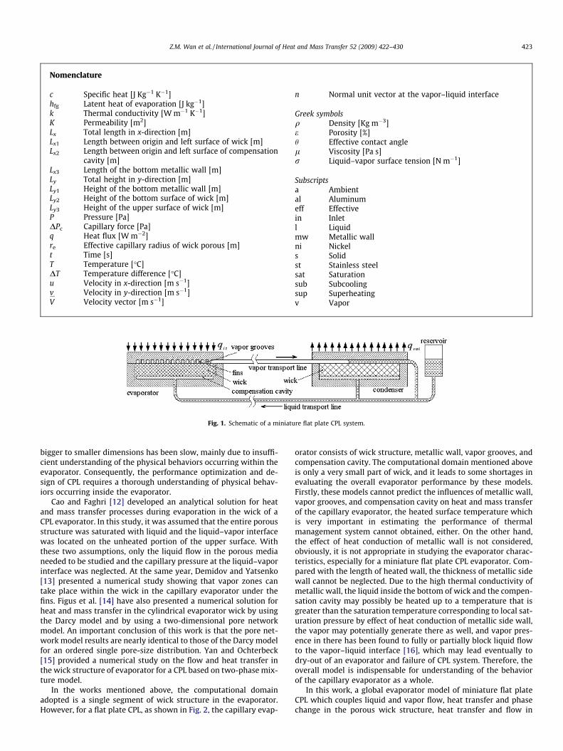
Fig. 1. Schematic of a miniature flat plate CPL system.
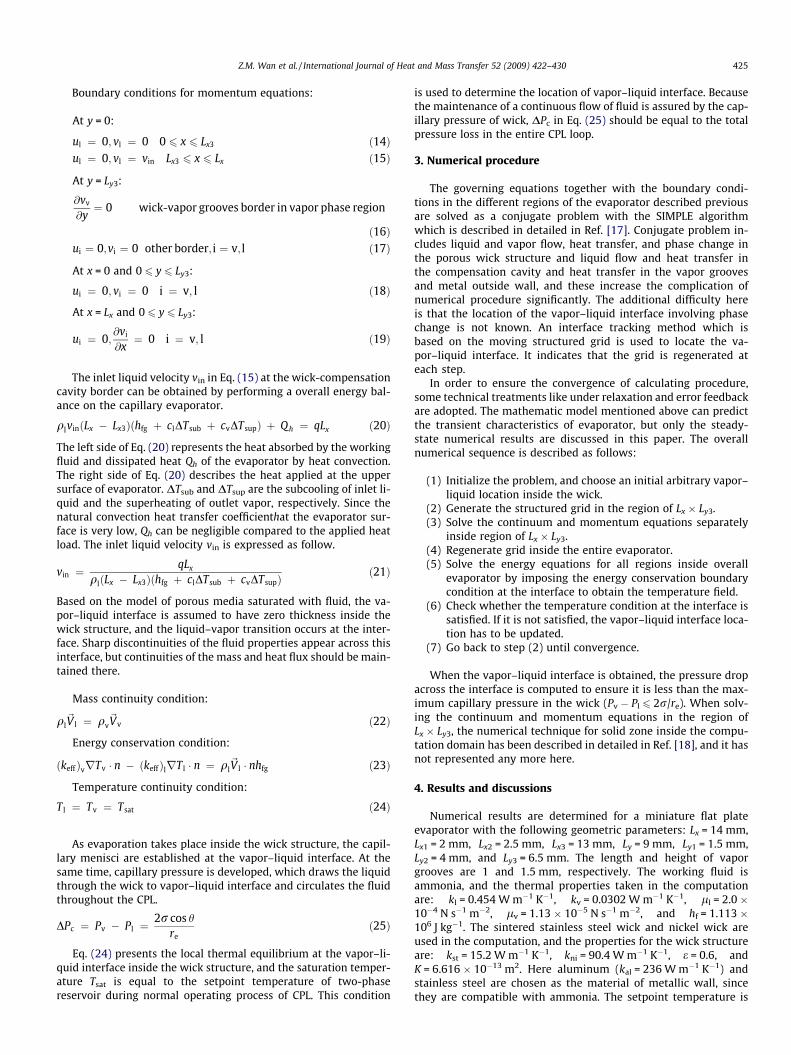
Nomenclature
c Specific heat [J Kg�1 K�1]hfg Latent heat of evaporation [J kg�1]k Thermal conductivity [W m�1 K�1]K Permeability [m2]Lx Total length in x-direction [m]Lx1 Length between origin and left surface of wick [m]Lx2 Length between origin and left surface of compensation
cavity [m]Lx3 Length of the bottom metallic wall [m]Ly Total height in y-direction [m]Ly1 Height of the bottom metallic wall [m]Ly2 Height of the bottom surface of wick [m]Ly3 Height of the upper surface of wick [m]P Pressure [Pa]DPc Capillary force [Pa]q Heat flux [W m�2]re Effective capillary radius of wick porous [m]t Time [s]T Temperature [�C]DT Temperature difference [�C]u Velocity in x-direction [m s�1]v Velocity in y-direction [m s�1]V*
Velocity vector [m s�1]
n Normal unit vector at the vapor–liquid interface
Greek symbolsq Density [Kg m�3]e Porosity [%]h Effective contact anglel Viscosity [Pa s]r Liquid–vapor surface tension [N m�1]
Subscriptsa Ambiental Aluminumeff Effectivein Inletl Liquidmw Metallic wallni Nickels Solidst Stainless steelsat Saturationsub Subcoolingsup Superheatingv Vapor
Z.M. Wan et al. / International Journal of Heat and Mass Transfer 52 (2009) 422–430 423
bigger to smaller dimensions has been slow, mainly due to insuffi-cient understanding of the physical behaviors occurring within theevaporator. Consequently, the performance optimization and de-sign of CPL requires a thorough understanding of physical behav-iors occurring inside the evaporator.
Cao and Faghri [12] developed an analytical solution for heatand mass transfer processes during evaporation in the wick of aCPL evaporator. In this study, it was assumed that the entire porousstructure was saturated with liquid and the liquid–vapor interfacewas located on the unheated portion of the upper surface. Withthese two assumptions, only the liquid flow in the porous medianeeded to be studied and the capillary pressure at the liquid–vaporinterface was neglected. At the same year, Demidov and Yatsenko[13] presented a numerical study showing that vapor zones cantake place within the wick in the capillary evaporator under thefins. Figus et al. [14] have also presented a numerical solution forheat and mass transfer in the cylindrical evaporator wick by usingthe Darcy model and by using a two-dimensional pore networkmodel. An important conclusion of this work is that the pore net-work model results are nearly identical to those of the Darcy modelfor an ordered single pore-size distribution. Yan and Ochterbeck[15] provided a numerical study on the flow and heat transfer inthe wick structure of evaporator for a CPL based on two-phase mix-ture model.
In the works mentioned above, the computational domainadopted is a single segment of wick structure in the evaporator.However, for a flat plate CPL, as shown in Fig. 2, the capillary evap-
orator consists of wick structure, metallic wall, vapor grooves, andcompensation cavity. The computational domain mentioned aboveis only a very small part of wick, and it leads to some shortages inevaluating the overall evaporator performance by these models.Firstly, these models cannot predict the influences of metallic wall,vapor grooves, and compensation cavity on heat and mass transferof the capillary evaporator, the heated surface temperature whichis very important in estimating the performance of thermalmanagement system cannot obtained, either. On the other hand,the effect of heat conduction of metallic wall is not considered,obviously, it is not appropriate in studying the evaporator charac-teristics, especially for a miniature flat plate CPL evaporator. Com-pared with the length of heated wall, the thickness of metallic sidewall cannot be neglected. Due to the high thermal conductivity ofmetallic wall, the liquid inside the bottom of wick and the compen-sation cavity may possibly be heated up to a temperature that isgreater than the saturation temperature corresponding to local sat-uration pressure by effect of heat conduction of metallic side wall,the vapor may potentially generate there as well, and vapor pres-ence in there has been found to fully or partially block liquid flowto the vapor–liquid interface [16], which may lead eventually todry-out of an evaporator and failure of CPL system. Therefore, theoverall model is indispensable for understanding of the behaviorof the capillary evaporator as a whole.
In this work, a global evaporator model of miniature flat plateCPL which couples liquid and vapor flow, heat transfer and phasechange in the porous wick structure, heat transfer and flow in

Fig. 2. Schematic of miniature flat plate evaporator.
424 Z.M. Wan et al. / International Journal of Heat and Mass Transfer 52 (2009) 422–430
the compensation cavity and heat transfer in the vapor grooves andmetallic wall is presented. The entire evaporator was solvednumerically with SIMPLE algorithm as a conjugate problem. Theinfluences of heat load, liquid subcooling, wick material, metallicwall material and non-uniform heat fluxes on the evaporator per-formance are discussed in detail, and the side wall effect heattransfer limit caused by heat conduction of metallic side wall isinvestigated as well. To the best of our knowledge, the overallevaporator model has not been proposed before in the context ofcapillary evaporators.
2. Mathematical model
As the evaporator is taken to be symmetric, a half of evaporatorcross section is selected as the computational domain, as shown inFig. 3. The origin of the coordinate system is located at the left bot-tom corner of evaporator.
To develop the mathematical model, the main assumptions aremade as follows:
(1) For simplicity, the vapor flow in the vapor grooves isneglected, and heat transfer is mainly by conduction.
(2) The porous media is rigid, homogenous, isotropic, and fullysaturated with fluid. There is local thermodynamic equilib-rium between solid phase and liquid or vapor phase.
(3) The fluid is incompressible and has the constant properties.
For the space environment, the effect of gravity is neglected.The heat and mass transfer for the liquid and vapor regions inthe wick structure are based on the volume-averaged techniqueand Brinkman–Darcy–Forchheimer model of porous media.
The governing equations of the global evaporator can be writtenas follows.(1) Metallic wall
ðqcÞmw@T@t¼ kmw
@2T@x2 þ
@2T@y2
!ð1Þ
(2) Vapor grooves
ðqcÞv@T@t¼ kv
@2T@x2 þ
@2T@y2
!ð2Þ
Fig. 3. Computation domain and coordinate system.
(3) Wick structureContinuum equation:
@ðeiqiÞ@t
þ r � ðqi~V iÞ ¼ 0 ð3Þ
Momentum equation:
qi
ei
@~V i
@tþ qi
e2i
rð~V i � rÞ~V i ¼ �rp � li
Kþ qiCffiffiffiffi
Kp j~V ij
� �~V i þ
li
eir2~V i
ð4ÞEnergy equation:
ðqcÞi@T@tþ qicið~V i � rÞT ¼ ðkeffÞir2T ð5Þ
(4) Compensation cavity
Continuum equation:
@ql
@tþ r � ðql
~V lÞ ¼ 0 ð6Þ
Momentum equation:
ql@~V l
@tþ qlrð~V l � rÞ~V l ¼ �rp þ llr2~V l ð7Þ
Energy equation:
qlcl@T@tþ qlclð~V i � rÞT ¼ klr2T ð8Þ
where i = l, v; C is the Forchheimer’s constant; (keff) is the effectivethermal conductivity, (keff)i = eki + (1 � e)ks; ðqcÞ is the density–capacity heat product defined in the energy equations, ðqcÞi ¼eqici þ ð1� eÞqscs.
The heat transfer in these regions is coupled, and the conserva-tion equations must be solved as a conjugate problem. The bound-ary conditions of energy and momentum equations can bedescribed below.
Boundary conditions for energy equations:
At x = 0:
kmw@T@x¼ 0 ð9Þ
At x = Lx:
@T@x¼ 0 ð10Þ
At y = 0:
kmw@T@y¼ 0 0 6 x 6 Lx3 ð11Þ
T ¼ T in Lx3 6 x 6 Lx ð12Þ
At y = Ly:
kmw@T@y¼ q ð13Þ
The conjugate boundary conditions exist at the interface of tworegions. The heat flux and temperatures should be continuous atthe interface on both sides.
Z.M. Wan et al. / International Journal of Heat and Mass Transfer 52 (2009) 422–430 425
Boundary conditions for momentum equations:
At y = 0:
ul ¼ 0; vl ¼ 0 0 6 x 6 Lx3 ð14Þul ¼ 0; vl ¼ vin Lx3 6 x 6 Lx ð15Þ
At y = Ly3:
@vv
@y¼ 0 wick-vapor grooves border in vapor phase region
ð16Þui ¼ 0;vi ¼ 0 other border; i ¼ v; l ð17Þ
At x = 0 and 0 6 y 6 Ly3:
ui ¼ 0; vi ¼ 0 i ¼ v; l ð18Þ
At x = Lx and 0 6 y 6 Ly3:
ui ¼ 0;@vi
@x¼ 0 i ¼ v; l ð19Þ
The inlet liquid velocity vin in Eq. (15) at the wick-compensationcavity border can be obtained by performing a overall energy bal-ance on the capillary evaporator.
qlvinðLx � Lx3Þðhfg þ clDTsub þ cvDTsupÞ þ Qh ¼ qLx ð20Þ
The left side of Eq. (20) represents the heat absorbed by the workingfluid and dissipated heat Qh of the evaporator by heat convection.The right side of Eq. (20) describes the heat applied at the uppersurface of evaporator. DTsub and DTsup are the subcooling of inlet li-quid and the superheating of outlet vapor, respectively. Since thenatural convection heat transfer coefficienthat the evaporator sur-face is very low, Qh can be negligible compared to the applied heatload. The inlet liquid velocity vin is expressed as follow.
vin ¼qLx
qlðLx � Lx3Þðhfg þ clDTsub þ cvDTsupÞð21Þ
Based on the model of porous media saturated with fluid, the va-por–liquid interface is assumed to have zero thickness inside thewick structure, and the liquid–vapor transition occurs at the inter-face. Sharp discontinuities of the fluid properties appear across thisinterface, but continuities of the mass and heat flux should be main-tained there.
Mass continuity condition:
ql~V l ¼ qv
~Vv ð22Þ
Energy conservation condition:
ðkeffÞvrTv � n � ðkeffÞlrT l � n ¼ ql~V l � nhfg ð23Þ
Temperature continuity condition:
T l ¼ Tv ¼ Tsat ð24Þ
As evaporation takes place inside the wick structure, the capil-lary menisci are established at the vapor–liquid interface. At thesame time, capillary pressure is developed, which draws the liquidthrough the wick to vapor–liquid interface and circulates the fluidthroughout the CPL.
DPc ¼ Pv � Pl ¼2r cos h
reð25Þ
Eq. (24) presents the local thermal equilibrium at the vapor–li-quid interface inside the wick structure, and the saturation temper-ature Tsat is equal to the setpoint temperature of two-phasereservoir during normal operating process of CPL. This condition
is used to determine the location of vapor–liquid interface. Becausethe maintenance of a continuous flow of fluid is assured by the cap-illary pressure of wick, DPc in Eq. (25) should be equal to the totalpressure loss in the entire CPL loop.
3. Numerical procedure
The governing equations together with the boundary condi-tions in the different regions of the evaporator described previousare solved as a conjugate problem with the SIMPLE algorithmwhich is described in detailed in Ref. [17]. Conjugate problem in-cludes liquid and vapor flow, heat transfer, and phase change inthe porous wick structure and liquid flow and heat transfer inthe compensation cavity and heat transfer in the vapor groovesand metal outside wall, and these increase the complication ofnumerical procedure significantly. The additional difficulty hereis that the location of the vapor–liquid interface involving phasechange is not known. An interface tracking method which isbased on the moving structured grid is used to locate the va-por–liquid interface. It indicates that the grid is regenerated ateach step.
In order to ensure the convergence of calculating procedure,some technical treatments like under relaxation and error feedbackare adopted. The mathematic model mentioned above can predictthe transient characteristics of evaporator, but only the steady-state numerical results are discussed in this paper. The overallnumerical sequence is described as follows:
(1) Initialize the problem, and choose an initial arbitrary vapor–liquid location inside the wick.
(2) Generate the structured grid in the region of Lx � Ly3.(3) Solve the continuum and momentum equations separately
inside region of Lx � Ly3.(4) Regenerate grid inside the entire evaporator.(5) Solve the energy equations for all regions inside overall
evaporator by imposing the energy conservation boundarycondition at the interface to obtain the temperature field.
(6) Check whether the temperature condition at the interface issatisfied. If it is not satisfied, the vapor–liquid interface loca-tion has to be updated.
(7) Go back to step (2) until convergence.
When the vapor–liquid interface is obtained, the pressure dropacross the interface is computed to ensure it is less than the max-imum capillary pressure in the wick (Pv � Pl 6 2r/re). When solv-ing the continuum and momentum equations in the region ofLx � Ly3, the numerical technique for solid zone inside the compu-tation domain has been described in detailed in Ref. [18], and it hasnot represented any more here.
4. Results and discussions
Numerical results are determined for a miniature flat plateevaporator with the following geometric parameters: Lx = 14 mm,Lx1 = 2 mm, Lx2 = 2.5 mm, Lx3 = 13 mm, Ly = 9 mm, Ly1 = 1.5 mm,Ly2 = 4 mm, and Ly3 = 6.5 mm. The length and height of vaporgrooves are 1 and 1.5 mm, respectively. The working fluid isammonia, and the thermal properties taken in the computationare: kl = 0.454 W m�1 K�1, kv = 0.0302 W m�1 K�1, ll = 2.0 �10�4 N s�1 m�2, lv = 1.13 � 10�5 N s�1 m�2, and hf = 1.113 �106 J kg�1. The sintered stainless steel wick and nickel wick areused in the computation, and the properties for the wick structureare: kst = 15.2 W m�1 K�1, kni = 90.4 W m�1 K�1, e = 0.6, andK = 6.616 � 10�13 m2. Here aluminum (kal = 236 W m�1 K�1) andstainless steel are chosen as the material of metallic wall, sincethey are compatible with ammonia. The setpoint temperature is

426 Z.M. Wan et al. / International Journal of Heat and Mass Transfer 52 (2009) 422–430
35 �C, which is the fluid saturated temperatureTsat, and Tin = 25 �C.The grid schemes of global evaporator are 142 � 92.
Fig. 4 shows the liquid phase velocity vectors in the evaporator.Fig. 4(a) describes the liquid velocity vectors inside the porouswick, and the magnitude of liquid velocity is 10�5. As seen, thewick structure contains vapor region under the fins separated fromthe liquid region by the vapor–liquid interface. Naturally, the thingaps between the fins and upper surface of wick saturated by vaporappear, these gaps allow the vapor to escape from the wick to va-por grooves. The shape of vapor–liquid interface is wavy near theupper surface of wick, and the vapor region is very small. The li-quid flows into wick from the wick-compensation cavity border,and is driven to evaporate at the vapor–liquid interface by the wickcapillary force. Fig. 4(a) also shows that the liquid evaporationmostly takes place near the upper surface of wick structure, andthe liquid velocity is nearly uniform in most liquid zone. At thesame time, because of heat conduction effect of side metallic wall,the liquid evaporation also occurs in the vicinity of left-hand sur-face of wick. Since the vapor zone is very small, the vapor velocityvectors are not given in this paper. Fig. 4(b) presents the results forthe liquid velocity vectors in the compensation cavity. As seen, thevelocity near the inlet is uniform along the flow direction, and far
Fig. 4. Liquid velocity vectors (aluminum wall, stainless steel wick, q = 4 � 104 W m
from the inlet, the velocity decreases gradually. Due to liquid evap-oration occurs mostly in the vicinity of the upper surface of wick,the liquid nearly uniformly enters the wick from compensationcavity, as shown in Fig. 4(b).
Fig. 5 shows the temperature distributions of the evaporatorfor different heat fluxes. Because of great difference in thermalconductivity between the metallic fins and vapor, heat is trans-ferred to wick mainly by conduction of the fins, and the shapeof isotherms near the upper surface of wick structure is wavy.The shape of vapor–liquid interface where the temperature con-tour level is equal to the saturated temperature of 35 �C insidethe wick is also wavy, and it is mainly determined by the geomet-ric parameters of fins and vapor grooves. The vapor–liquid inter-face locates in the vicinity of the upper and left surface of wickstructure, as has been observed by the visualization experimentof Zhao et al. [19]. When the heat flux is increased, the vapor–li-quid interface inside the wick moves away from the fins and thesize of the vapor zone and the gaps enlarges, these can be foundin Fig. 5(b). Due to high thermal conductivity of aluminum, thetemperature gradients inside the metallic wall are very small,which means the temperatures of the evaporator heated surfaceare almost uniform.
�2, DTsub = 10 �C). (a) In the wick structure and (b) in the compensation cavity.
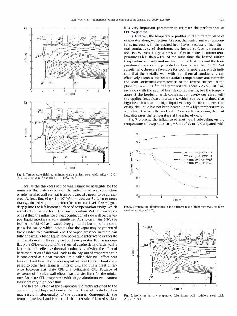
Fig. 5. Temperature fields (aluminum wall, stainless steel wick, DTsub = 10 �C).(a) q = 4 � 104 W m�2 and (b) q = 8 � 104W �m�2.
Fig. 6. Temperature distributions in the different plane (aluminum wall, stainlesssteel wick, DTsub = 10 �C).
Fig. 7. isotherms in the evaporator (aluminum wall, stainless steel wick,DTsub = 20 �C).
Z.M. Wan et al. / International Journal of Heat and Mass Transfer 52 (2009) 422–430 427
Because the thickness of side wall cannot be negligible for theminiature flat plate evaporator, the influence of heat conductionof side metallic wall on heat transport capacity needs to be consid-ered. At heat flux of q = 4 � 104 W m�2, because kal is large morethan kst, the left vapor–liquid interface (contour level of 35 �C) goesdeeply into the left bottom surface of compensation cavity, whichreveals that it is safe for CPL normal operation. With the increasesof heat flux, the influence of heat conduction of side wall on the va-por–liquid interface is very significant. As shown in Fig. 5(b), theisotherm of 35 �C has invaded deeply into the bottom of the com-pensation cavity, which indicates that the vapor may be generatedthere under this condition, and the vapor presence in there canfully or partially block liquid to vapor–liquid interface to evaporateand results eventually in dry-out of the evaporator. For a miniatureflat plate CPL evaporator, if the thermal conductivity of side wall islarger than the effective thermal conductivity of wick, the effect ofheat conduction of side wall leads to the day-out of evaporator, thisis considered as a heat transfer limit, called side wall effect heattransfer limit here. It is a very important heat transfer limit com-pared to other heat transfer limits of CPL, and this is great differ-ence between flat plate CPL and cylindrical CPL. Because ofexistence of the side wall effect heat transfer limit for the minia-ture flat plate CPL, evaporator with single aluminum wall cannottransport very high heat flux.
The heated surface of the evaporator is directly attached to theapparatus, and high and uneven temperatures of heated surfacemay result in abnormality of the apparatus. Consequently, thetemperature level and isothermal characteristic of heated surface
is a very important parameter to estimate the performance ofCPL evaporator.
Fig. 6 shows the temperature profiles in the different plane ofevaporator along x-direction. As seen, the heated surface tempera-tures increase with the applied heat fluxes. Because of high ther-mal conductivity of aluminum, the heated surface temperaturelevel is low, even though at q = 8 � 104 W m�2, the maximum tem-perature is less than 40 �C. At the same time, the heated surfacetemperature is nearly uniform for uniform heat flux and the tem-perature difference along heated surface is less than 1.5 �C. Notsurprisingly, these are favorable for cooling apparatus, which indi-cate that the metallic wall with high thermal conductivity caneffectively decrease the heated surface temperatures and maintainthe good isothermal characteristic of the heated surface. In theplane of y = 4 � 10�3 m, the temperature (about x < 2.5 � 10�3 m)increases with the applied heat fluxes increasing, but the temper-ature at the border of wick-compensation cavity decreases withthe applied heat fluxes increasing, which can be explained thathigh heat flux leads to high liquid velocity in the compensationcavity, the liquid has not been heated up to a high temperature le-vel before it arrives the wick inlet. As a result, increasing the heatflux decreases the temperature at the inlet of wick.
Fig. 7 presents the influence of inlet liquid subcooling on thetemperature of evaporator at q = 8 � 104 W m�2. Compared with

Fig. 9. Temperature difference between saturated temperature and bottom wicksurface temperature (aluminum wall, DTsub = 10 �C, q = 8 � 104 W m�2).
428 Z.M. Wan et al. / International Journal of Heat and Mass Transfer 52 (2009) 422–430
Fig. 5(b), it can be found that increasing the inlet liquid subcoolingincreases the temperature gradients inside the wick. Due to heatconvection of liquid with lower temperature in the compensationcavity and wick, high subcooling aids in preventing vapor forma-tion in the compensation cavity and inside the bottom wick, andit is favorable for normal operation of CPL. Furthermore, Fig. 7 alsoshows the left vapor–liquid interface locates near the bottom leftcorner of compensation cavity, and the isotherm of saturated tem-perature has not invaded deeply into the bottom surface of thecompensation cavity. Therefore, increasing the liquid subcoolingcan enhance the side wall effect heat transfer limit of the evapora-tor and help to increase the safety of miniature flat plate CPL.
To evaluate the influence of thermal conductivity of wick on theperformance of evaporator, the sintered nickel wick is used as amaterial of high thermal conductivity in the computation. Fig. 8shows the temperature distributions in the evaporator with nickelwick. Compared to evaporator with sintered stainless steel wick(Fig. 5b), as seen from Fig. 8, heat conduction of side wall decreasescorrespondingly, and the left vapor–liquid interface locates at theleft surface of compensation cavity and the isotherm of saturatedtemperature has not invaded deeply into the compensation cavity.Because of high thermal conductivity of nickel wick, the heat con-duction to the compensation cavity through the wick increases,and the temperature gradients are small and the liquid in the com-pensation cavity is heated to a higher temperature level. Fig. 9shows the temperature difference between saturated temperatureand bottom wick surface temperature along x-direction for differ-ent material wick. The temperature difference for stainless steelwick is much greater than that for nickel wick, and lower temper-ature difference is found to increase the chance of an eventualevaporator deprime [20].
In order to investigate the effects of wall material on the perfor-mance of evaporator, the stainless steel wall and combined wall(upper wall material is aluminum, side and bottom wall materialis stainless steel) are also used in the computation. Fig. 10 showsthe temperature distributions in the evaporator with different wallmaterial at q = 12 � 104 W m�2. As shown in Fig. 10(a), due to lowthermal conductivity for stainless steel wall, the temperature gra-dients are very large in the upper wall zone, and decrease in thewick and bottom wall zone. At the same time, deleterious effectsof heat conduction of side wall decreases, and the isotherm of sat-urated temperature has not invaded deeply into the compensationcavity bottom, the CPL can operate safely under this condition. Asshown in Fig. 10(b), because of high thermal conductivity of upper
Fig. 8. Temperature fields (aluminum wall, nickel wick, DTsub = 10 �C,q = 8 � 104 W m�2).
Fig. 10. Isotherms in the evaporator (stainless steel wick, DTsub = 10 �C). (a)Stainless steel wall and (b) combined wall.
wall, the temperature gradients are small in the upper wall zone,but temperature gradients are large inside the wick and side andbottom wall. The effect of heat conduction of side wall is obviouslyless, and the isotherm of saturated temperature only arrives at theleft bottom wick surface, which indicates that CPL has not reached

Z.M. Wan et al. / International Journal of Heat and Mass Transfer 52 (2009) 422–430 429
the side wall effect heat transfer limit. As discuss above, it indicatesthat side wall with low thermal conductivity is more suitable fordissipating high heat fluxes. On the other hand, at q = 12 �104 W m�2, the heated surface temperature of evaporator withstainless steel wall is more than 71.4 �C, which is deleterious forthe normal operation of cooled apparatus. But the heated surfacetemperature of evaporator with combined wall is about 43.6 �C,it is moderate for the cooled apparatus, and the temperature distri-bution along the heated surface is more uniform. Under this condi-tion, the cooled apparatus can operate effectively and have a longlife. Thereby, the thermal conductivity of wall has a significantinfluence on the performance of miniature flat plate CPL evapora-tor, and upper wall with high thermal conductivity results in lowtemperature and good isothermal characteristic of heated surface.The flat plate evaporator with combined wall improves the heattransport capacity and maintains an appropriate temperature levelof the heated surface.
The heat distribution induced by cooled apparatus is not alwaysuniform during their normal operations, and the effect of non-uni-form heat flux needs to be assessed. In the numerical computation,it assumes that the heat flux distribution varies along the heatedsurface as follow:
qðxÞ ¼ 104 � ½16 � 12ðx=lx � 1Þ2� ð26Þ
Fig. 11 shows the temperature distribution in the evaporator withdifferent wall material in the case of non-uniform heat flux. As seen,
Fig. 11. Temperature fields for non-uniform heat flux (stainless steel wick,DTsub = 10 �C). (a) Stainless steel wall and (b) combined wall.
for the non-uniform heat flux, the isotherm of saturated tempera-ture in the evaporator with stainless steel wall or combined wallhas not invaded into the compensation cavity, which indicates thecapillary evaporator operates safely in the case of non-uniform heatflux. Fig. 12 presents the effect of non-uniform heat flux on theheated surface temperature. In the case of stainless steel wall, theshape of heated surface temperature is wavy due to the effect of va-por grooves. As expected, the peak temperature occurs at the centerof heated surface where the heat flux is maximal. In the case of thestainless steel wall, because of low thermal conductivity, the max-imal temperature is higher than 84 �C, and the peak temperaturedifference on the heated surface is more than 28 �C. High tempera-ture and large temperature difference along the heated surface mayresult in short-life of the cooled apparatus. However, in the case ofcombined wall, the heated surface temperature is moderate and al-most uniform, which implies that evaporator with the combinedwall has more strong ability to accommodate the non-uniform heatflux than that with stainless steel wall.
5. Conclusions
An overall model for the miniature flat plate CPL evaporator ispresented, which includes liquid and vapor flow, heat transferand phase change in the porous wick structure, liquid flow andheat transfer in the compensation cavity and heat transfer in thevapor grooves and metallic wall. The governing equations for dif-ferent zones are solved numerically as a conjugate problem.
The liquid evaporation takes place near the upper and left sur-face of wick structure in the evaporator, and with the increases ofthe applied heat fluxes, the vapor–liquid interface moves awayfrom the fins and the size of the vapor zone enlarges. On the otherhand, lower temperature liquid exists at the entrance of wick athigher heat flux, and convection of lower temperature liquid helpsto prevent the vapor formation inside the bottom wick. For theminiature flat plate CPL evaporator, the effect of heat conductionof side metallic wall on the behaviors of evaporator is great, andside wall effect heat transfer limit is introduced to estimate theheat transport capacity of the evaporator. Due to the existence ofside wall effect heat transfer limit, the evaporator with aluminumwall has a low heat transport capability. Increasing the inlet liquidsubcooling helps to prevent the vapor formation inside the com-pensation cavity and the bottom wick structure and also increasesthe side wall effect heat transfer limit. The evaporator with high
Fig. 12. Temperature distributions along heat surface for non-uniform heat flux(stainless steel wick, DTsub = 10 �C).

430 Z.M. Wan et al. / International Journal of Heat and Mass Transfer 52 (2009) 422–430
thermal conductivity wick, such as nickel wick, can improve theside wall effect heat transfer limit, but increases the chance of aneventual evaporator deprime. The flat plate evaporator of singlealuminum wall results in lower side wall effect heat transfer limit,but leads to lower temperature level and good isothermal behaviorof the heated surface. On the other hand, the evaporator with sin-gle stainless steel wall leads to higher heat transport capacity, butto higher temperature level of the heated surface. The evaporatorwith combined wall (upper wall with aluminum, side and bottomwall with stainless steel) increases side wall effect heat transferlimit, and maintains an appropriate temperature level and goodisothermal characteristic on the heated surface and enhances theability to accommodate the non-uniform heat flux, which implythat the CPL can operate safely and cooled apparatus can also workeffectively under higher heat fluxes and non-uniform heat fluxes.
The present overall numerical model of miniature flat plate CPLevaporator can effectively estimate the heat transfer capacity ofevaporator and evaluate the temperature level of the heated sur-face, and it is useful for the evaporator design and performanceoptimization of miniature flat plate CPL.
Acknowledgement
The current work is supported by the National Key Basic Re-search Development Program of China (No. 2007CB206901).
References
[1] R. Nadalini, F. Bodendieck, The thermal control system for a network missionon Mars: The experience of the Netlander mission, Acta Astronautica 58 (11)(2006) 564–575.
[2] T.D. Swanson, G.C. Birur, NASA thermal control technologies for roboticspacecraft, Applied Thermal Engineering 23 (9) (2003) 1055–1065.
[3] S. Clayton, D. Martin, J. Baumann, Mars surveyor thermal management using afixed conductance capillary pumped loop, SAE Paper No.972467, 1997.
[4] M. Nikitkin, B. Cullimore, CPL and LHP technologies: what are the differences,what are the similarities? SAE Paper No.981587, 1998.
[5] D. Butler, L. Ottenstein, J. Ku, Design evolution of the capillary pumped loop(CAPL-2) flight experiment, SAE Paper No.961431, 1996.
[6] T. Hoang, J. Ku, Hydrodynamic aspect of capillary pumped loop, SAE PaperNo.961435, 1996.
[7] E. Pouzet, J.L. Joly, V. Platel, et al., Dynamic response of a capillary pumped loopsubjected to various heat load transients, International Journal of Heat andMass Transfer 47 (10) (2004) 2293–2316.
[8] P.C. Chen, W.K. Lin, The application of capillary pumped loop for cooling ofelectronic components, Applied Thermal Engineering 21 (11) (2001) 1739–1754.
[9] E. Bazzo, R.R. Riehl, Operation characteristics of a small-scale capillary pumpedloop, Applied Thermal Engineering 23 (6) (2003) 687–705.
[10] S. Randeep, A. Aliakbar, D. Chris, et al., Miniature loop heat pipe with flatevaporator for cooling computer CPU, IEEE Transaction on Components andPackaging Technologies 30 (1) (2007) 42–49.
[11] I. Muraoka, F.M. Ramos, V.V. Vlassov, Experimental and theoreticalinvestigation of a capillary pumped loop with a porous element in thecondenser, International Communications in Heat and Mass Transfer 25 (8)(1998) 1085–1094.
[12] Y. Cao, A. Faghri, Analytical solutions of flow and heat transfer in aporous structure with partial heating and evaporation on the uppersurface, International Journal of Heat and Mass Transfer 37 (10) (1994)1525–1553.
[13] A.S. Demidov, E.S. Yatsenko, Investigation of heat and mass transfer in theevaporation zone of a heat pipe operating by the ‘inverted meniscus’ principle,International Journal of Heat and Mass Transfer 37 (14) (1994) 2155–2163.
[14] C. Figus, Y.L. Bray, S. Bories, et al., Heat and mass transfer with phase change ina porous structure partially heated: continuum model and pore networksimulations, International Journal of Heat and Mass Transfer 42 (14) (1999)2557–2569.
[15] Y.H. Yan, J.M. Ochterbeck, Numerical investigation of the steady-stateoperation of a cylindrical capillary pumped loop evaporator, Journal ofElectronic Packaging 125 (2) (2003) 251–260.
[16] J. Ku, Start-up issues of capillary pumped loops, Proceedings of the NinethInternational Heat Pipe Conference, Albuquerque, NM, 1995, pp. 994–1001.
[17] W.Q. Tao, Numerical Heat Transfer, Xi’an Jiao Tong University Press, Xi’an,China, 2001 (in Chinese).
[18] M. Yang, W.Q. Tao, Three-dimensional natural convections in an enclosurewith an internal isolated vertical plate, ASME Journal of Heat Transfer 117(1995) 619–625.
[19] T.S. Zhao, Q. Liao, On capillary-driven flow and phase-change heat transfer in aporous structure heated by a finned surface: measurements and modeling,International Journal of Heat and Mass Transfer 43 (4) (2000) 1141–1155.
[20] J.L. Tim, M. Issam, Thermal transients in a capillary evaporator prior to theinitiation of boiling, International Journal of Heat and Mass Transfer 43 (21)(2000) 3937–3952.