Embed Size (px)
Citation preview

International Journal of Marine Energy 16 (2016) 209–219
Contents lists available at ScienceDirect
International Journal of Marine Energy
journal homepage: www.elsevier .com/locate / i jome
Experimental and CFD analysis of the wake characteristics oftidal turbines
http://dx.doi.org/10.1016/j.ijome.2016.07.0012214-1669/Crown Copyright � 2016 Published by Elsevier Ltd.This is an open access article under the CC BY license (http://creativecommons.org/licenses/by/4.0/).
⇑ Corresponding author.E-mail address: [email protected] (M.G. Gebreslassie).
Mulualem G. Gebreslassie a,⇑, Stephanie O. Sanchez c, Gavin R. Tabor b, Michael R. Belmont b,Tom Bruce d, Grégory S. Payne d, Ian Moon b
a EiT-M, Mekelle University, Endayesus Campus, P.O. Box 231, Mekelle, EthiopiabCEMPS, University of Exeter, North Park Road, Exeter EX4 4QF, UKcEnergy Systems Research Unit, Department of Mechanical and Aerospace Engineering, University of Strathclyde, 75 Montrose Street, Glasgow G1 1XJ, UKd Institute for Energy Systems, School of Engineering, The University of Edinburgh, Mayfield Road, Edinburgh EH9 3JL, UK
a r t i c l e i n f o
Article history:Received 17 July 2015Revised 5 July 2016Accepted 15 July 2016Available online 18 July 2016
Keywords:CFDIBF modelExperimentWake profiles
a b s t r a c t
This paper investigates the accuracy of the Computational Fluid Dynamics (CFD) basedImmersed Body Force (IBF) turbine modelling method for predicting the flow characteris-tics of a Momentum-Reversal-Lift type of tidal turbine. This empirically-based CFD modelhas been developed based on the actuator disc method enhanced with additional featuresto mimic the effect of the complex blade motion on the downstream wake, without thehigh computational costs of explicitly modelling the dynamic blade motion. The modelhas been calibrated against the flow characteristics data obtained from experiment andfound to perform well, although there are few inconsistencies in the flow patterns whichshow some of the limitations of the IBF model compared to a full dynamic blade motionsimulation. However, given the complexity and computational cost of modelling thedetailed blade motion the limitations of the IBF model are acceptable and will be usefulespecially for optimisation of arrays of devices where there is a significant computationaldemand.Crown Copyright � 2016 Published by Elsevier Ltd. This is an open access article under the
CC BY license (http://creativecommons.org/licenses/by/4.0/).
1. Introduction
Most researchers accept that simple momentum sink zone models such as actuator disc methods are unable to generatethe detailed physics of the flow produced by real turbines. However, because of their lower computational cost they are oneof the few computationally realistic approaches for gaining insight into the behaviour of substantial clusters of devices. Theprinciple of an actuator disc has been frequently utilized for modelling turbines both in experimental and computationalstudies. The disc acts as a momentum sink which is matched to the thrust coefficients of the turbine [1,2]. This methodhas been widely used for wind turbines as documented by [3,4]. Recently this method has been used in tidal turbines bothin experiments [2] and using Computational Fluid Dynamics (CFD) techniques [5–7].
Wake profiles measured from experiment conducted by [2] using porous disc have shown reasonable agreement withactuator disc-Reynolds Averaged Navier Stokes (RANS) models in equivalent CFD simulations. However, validation of theCFD model using data measured from experimental work on simplistic disc may not be the best option to analyse fidelityof the model and to apply this model in the real turbine applications. A recent study by [8] demonstrated that the actuator

210 M.G. Gebreslassie et al. / International Journal of Marine Energy 16 (2016) 209–219
disc-RANS model accurately predicts the wake of tidal turbines when compared with the wake measurements from exper-iment though they acknowledged that it lacks the capability to generate swirling flows and capture tip vortices.
Most of the studies showed that the accuracy of actuator disc methods in replicating the actual flow characteristics of thereal turbines varied significantly. Trying to represent all types of turbine designs by a single simplistic actuator disc modelmay aggravate its existing drawbacks and could be one of the reasons for those inaccuracies . Thus it is crucial to adapt themethod based on the details of the turbine under consideration to improve the accuracy of the models for predicting the flowcharacteristics.
The focus of this study is on the Momentum-Reversal-Lift (MRL) turbine designed based on a cylindrical cycloidal systemwhere each of three blades rotates 1800 for every full rotation of the main shaft. Details of the MRL turbine dimensions andits blade profile is shown in Figs. 2 and 5. This design allows the blades to provide torque through most of the cycle in bothlift and drag phases. It is this combination of both lift and drag which gives the turbine a high conversion efficiency over awide range of operating fluid velocities. The novel aspect of the device is the combination of lift and momentum reversal(drag) that is utilised to optimise the energy extraction. It has been known since the early days of aerodynamics that theforces on a plate held in a flowing stream consist of two orthogonal components:
1. Lift which acts perpendicularly to the flow direction.2. Drag (momentum reversal)- which acts parallel to the flow direction.
The blade rotation is nominally half that around the central shaft since this condition results in near optimum conditionsfor both lift and drag forces on each blade [9], but this is still under investigation and the exact details could be subjected tosome changes. Fig. 1 shows the rotation of the blade around the central axis presenting a variable incident angle to the flowduring the rotation cycle. The power is taken off from the central shaft and transferred to a generator. The blades are allowedto rotate about their own axis and also about a mutually central axis where the rotation axis is perpendicular to the flowdirection in contrast to the better known windmill device. There are several aspects to this configuration which give it poten-tial advantage particularly in water where the flow forces on the blades can be extremely high.
Since both the drag and lift exert forces, both of these can be used to extract energy from the fluid flow. Of these, lift hasbeen the subject of considerably more attention since it is the basis of winged flight and also the basis for propeller basedpropulsion, whereas drag has been viewed as a problem to be overcome in this context. Nevertheless, for a given plate areaand flow velocity, the drag force generally exceeds the lift force and is much less sensitive to the flow incident angle. TheMRL turbine and its configuration is capable of taking advantage of both these characteristics through the operating cycle.
It is surprising that there is a set of blade conditions where both lift and drag forces act uni-rotationally around the mainaxis such that the torque contribution is positive over the whole cycle. This allows both lift and drag forces to act together toproduce a large summed torque as described by [9].
Detailed CFD models of such machines (including blade geometry and blade motions) can be undertaken using dynamic(sliding) mesh or overset meshing techniques; however the ensuing calculations are computationally unrealistically expen-sive for more than a single turbine. Thus the use of simplified CFD based turbine modelling techniques becomes imperativefor such turbines. In view of this, an empirically-based CFD model called the Immersed Body Force (IBF) model was devel-oped based on the accepted methodology of the actuator disc but incorporating additional features that induce energyabsorption from the flow so as to generate a downstream wake structure which more closely reflects that of the real tur-bines. This model could easily be made applicable to other turbine designs with few modifications. Some of the advantagesof the IBF model include the capability of implementing drag and lift forces and the reduction of mesh resolution that isrequired compared to what would be required for a resolved blade simulation. This model has been used to analyse wakeinteractions of a small clusters of turbines as shown in [10–12].
Given that the long term goal of our work is to use the IBF model for large scale tidal farm modelling, it is important tovalidate the model’s fidelity against experimental data. Therefore, the aim of this paper is: (i) to validate the accuracy of the
Fig. 1. Torque on axis as a function of arm angle h and blade angle /.

M.G. Gebreslassie et al. / International Journal of Marine Energy 16 (2016) 209–219 211
IBF model for predicting the wake profiles of tidal turbines by comparing with experimental data measured from testing ascaled prototype of the MRL turbine; and (ii) to show that improved modelling techniques such as the IBF model could bedeveloped for other specific turbine designs whilst maintaining their modelling simplicity and cheaper computational cost.
2. Methodology
2.1. Computational modelling
2.1.1. Reynolds-averaged Navier–Stokes (RANS) modellingThe Navier–Stokes equations represent the equations of conservation of mass and momentum for a fluid in motion. How-
ever they are complex, coupled and non-linear, and thus insoluble analytically for anything but the simplest cases. For mostrealistic cases, computational solution using numerical methods, i.e. CFD, is the only practical approach. Particularly chal-lenging is the solution of turbulent flow in a fluid. Turbulent flow is characterised by the presence of quasi-random turbulenteddies on length- and time-scales ranging from large scales which drive the turbulence down to the Kolmogorov scale deter-mined by the physical viscosity. For most practical cases direct numerical simulation of the complete range of scales isimpossible; instead the flow is decomposed into an ‘average’ component and fluctuations about this average. The intentionis that the average component is smoother and computationally tractable, whilst the fluctuations are in some sense universaland can be replaced by a simpler statistical model known as a turbulence model. The Reynolds-averaged Navier–Stokes(RANS) equations are obtained in this way by statistical averaging of the equations of motion, dividing the flow into a deter-ministic mean flowwhich is steady or slowly varying and turbulent fluctuations around this mean. The unsteady RANS mod-elling approach solves the Reynolds averaged equations of mass and momentum conservation given in Eqs. (1) and (2)respectively [7,13]. The source term, Fb, represents the turbine’s resistance force against the flow as discussed inSection 2.1.3.
@Ui
@xi¼ 0 ð1Þ
@Ui
@tþ @UiUj
@xj¼ � 1
q@P@xi
þ @
@xjm
@Ui
@xjþ @Uj
@xi
� �� �þ @
@xj�U0
iU0i
� �þ Fb ð2Þ
where U is the Reynolds averaged velocity, P is the Reynolds averaged pressure; m is a kinematic viscosity, and U0iU
0i is the
Reynolds stress tensor. The Reynolds stress tensor is defined as:
�U0iU
0i ¼ mt
@Ui
@xjþ @Uj
@xi
� �� 23kdij ð3Þ
where k ¼ 12U
0iU
0i is the turbulent kinetic energy, and mt is the turbulent viscosity.
The Reynolds stress term, U0iU
0i, is modelled using the k-omega Shear Stress Transport turbulence model (kx� SST) [14].
The kx� SSTturbulence model has been used because of its capability of modelling separated flows.
2.1.2. Computational domain and inflow conditionsThe dimensions of the computational domain are taken from the test tank facility with far upstream and downstream
dimensions reduced to minimise the computational cost as the experimental measurements were taken within this domain.Details of the computational domain are shown in Fig. 2. The size of the turbine relative to the size of the computationaldomain is very small and thus the turbine details is not clear. For this reason the turbine detail was scaled up by 10 timesð10�Þ of the actual size as shown in Fig. 2 so that all the dimensions and profile of the blades are visible. This means thedimensions of the blades shown in the figure should be scaled down by 10 in order to get their actual size. Different meshresolution was used where the mesh was refined around the region of interest to resolve the shear layers while the rest of theregion was slightly coarsened to decrease the computational cost. The resolution of the mesh was developed based on amesh sensitivity study conducted by [11] on a different domain size with the turbine performance monitored to find meshindependent solutions.
The inflow conditions are required to be a realistic representation of the practical engineering situation, although some-times it is difficult to achieve these conditions due to constraints such as time, cost and technology. In this study, the undis-turbed flow profile of the test tank was established and the result shows that the velocity slightly varies with depth.However, data was measured at a limited number of points across the depth of the channel and makes it difficult to directlyuse this data as inlet to the computational domain. The best option is therefore to apply an approximate tidal velocity profiledeveloped by assuming a power law [15–17], which is matched to the experimental data as shown in Fig. 3. The power lawvelocity profile gives good approximations for most tidal current sites and it can be estimated by assuming a power law ofthe form:
uðyÞ ¼ umeany
0:32h
� �1=9ð4Þ

Fig. 2. Dimensions of the computational domain.
Fig. 3. Matched experimental and Power law velocity profiles at the inlet to the computational domain.
212 M.G. Gebreslassie et al. / International Journal of Marine Energy 16 (2016) 209–219
where: umean is the mean velocity, y is the vertical height, and h is the depth of water level.The turbulence intensity was measured in the experiment and found to be around 3% and a similar value was prescribed
at the inlet to the computational domain to replicate the actual conditions of the test tank. Computations were performedusing the Open Source object-oriented C++ library, OpenFOAM, [18–20]. It uses Finite Volume Method solution technique inwhich the flow equations are volume-integrated over a discrete volume obtained by dividing the computational domain[20].
Tidal turbines may operate quite close to the water surface. However studies by [21–23] showed that the effect of thedynamics of the free surface on the wake profiles is minimal. In this study, the interest is on the wake profiles and thus mod-elling the free surface was excluded with a symmetry plane boundary condition used at the top of the computational domaininstead of a more sophisticated multiphase technique such as Volume of Fluid (VoF). This also improved convergence of thesimulations as VoF methods are much less stable than single phase models.
2.1.3. Turbine modellingMost researchers accept that simple momentum sink zone models such as the actuator disc methods are crude and make
it difficult to incorporate energy loss processes. However, they are one of the few computationally realistic approaches forgaining insight into the behaviour of substantial clusters of devices. This study builds upon this accepted methodology byincorporating additional geometric features that induce energy absorption from the flow which also lead to a downstreamwake structure intended to reflect more closely those of the real turbines than simple momentum sink zone models. The

M.G. Gebreslassie et al. / International Journal of Marine Energy 16 (2016) 209–219 213
turbine modelling method adopted for this study is therefore referred to as the Immersed Body Force (IBF) model, which is anovel turbine modelling technique developed by the authors of this paper [11,23]. The IBF model is capable of three roles:
1. Estimating the downstream wake structure.2. Allowing calculation of the energy that can be extracted from the flow together with a method of relating this to methods
of estimating the useful power extracted by the turbine which can be validated against experiments. This typicallyrequires access to a fully detailed CFD model as an intermediate step.
3. Providing information about the free surface interaction. This is important in the class of machines considered herebecause they are designed to be deployed close to the surface, often supported by floating pontoons. Thus in principlepitch resonance of the pontoons could occur with undesirable results.
For the IBF approach, a forcing function (Fb) which has units of force per unit mass representing the resistance by the tur-bine against the flow is used to create momentum change. The force function was imposed in the Navier–Stokes equationsand a code was developed by considering drag (FRD) and lift (FRL) resistance forces applied by the blades on the fluid flow asshown in Fig. 4. The forces are imposed on the volume of the blades and vortex ring which creates cylindrical shape to matchdesign of the MRL turbine shown in Fig. 5. This is different to the disc shape commonly used to represent the conventionalaxial type of tidal turbines.
The force applied by the vertical blade was considered entirely as a drag resistance force while the other two blades haveboth drag and lift resistance forces. This force is a reaction force to the forces applied by the flow on the blades. The forcingfunction can be defined as:
Fb ¼ FRD þ FRL ð5Þ
The IBF model comprises two parts as shown in Fig. 4:1. A set of resistance forces seated on the cells corresponding to the fixed blade positions.2. A force ring designed to represent the effect of the main turbine vortex.
Both 1 and 2 contain the free parameters (FRD and FRL) that define the associated resistances against the incoming flow. Thistype of representation has several advantages as summarised below:
� It reduces the requirement of mesh resolution at the surface because there is no physical presence of the blades in themodel, which minimises the requirement of fine meshing to treat the blade surface and fluid interaction.
� It is applied in a volume which creates complex motions within the turbine housing.� The geometric features lead to downstream wake structures intended to reflect more closely those of the real turbines.� If the physical blades were to use, they will be simply as solid boundaries imposing blockage but in the case of using theresistance forces, there is a flow of fluid through it similar to the porous region used in the application of actuator discmethod. However, if excessive resistance were to be used, it will act as a blockage body similar to the physical body ofthe blades.
� It allows application of both drag and lift resistances against the flow based on the blade position.
Avoiding modelling the blade motions means that pressure integration over the blade surface cannot be used to directlycalculate the mechanical power extracted by the machine from the flow. Consequently, published research on simplifieddescriptions of turbines of all kinds has focussed upon calculating the energy lost from the flow. Typical examples of thisare the various developments of momentum sink models (e.g. actuator disc descriptions) or Darcy flow based models thatimplicitly represent the turbine by a viscous dissipation sink region . Examples of this approach are given in [3,4,6].
A similar approach has been undertaken in the work presented here. For this reason, it is difficult to utilise any loadingsmeasured in the experiment directly to the CFD code as a resistance force because of the significant difference between themechanical power absorbed by the machine and the total energy lost from the flow. The best approach is therefore to find aself consistent match of the flow profiles from the experiment and CFD by varying the loadings in the CFD calculations. Thisprocess can provide the necessary loading that can be used in the CFD code in order to predict the accurate wake recovery.With the correct loadings, CFD calculations can then be conducted to investigate the effect of wake interactions, and thus thelocation of individual devices in a tidal stream farm can be optimised to generate maximum power output. This approach iscost effective compared to full scale experimental works.
2.2. Experimental procedure
CFD simulations have been compared with experimental measurements of the MRL turbine conducted in a Wave-Currentcirculating tank (Fig. 7a) at IFREMER, France. The tank’s dimensions are 4 m wide, 2 m deep and 18 m in length.
An MRL turbine (Fig. 5) with dimensions of 0.164 m diameter, 0.3 m blade span, and 0.095 m blade chord was used in theexperiments. Two sided plates were included in the design, one on the top and one on the bottom to increase the Pelton andthe ground effects, respectively.

Fig. 4. Body forces applied by each blade and annular section (annular method).
214 M.G. Gebreslassie et al. / International Journal of Marine Energy 16 (2016) 209–219
2.2.1. Calibration procedureThe turbine load was provided by a dashpot system and a gear system that connects the rotor and the dashpot. The gear
ratio used in the experiments was 12–24. The damping was provided by the viscous fluid contained in the dashpot with aviscosity of 250,000 cst.
The calibration was carried out with a torque rig composed of a contactless rotary torque transducer rated at 2 Nm, a halleffect sensor and a Crouzet DC Motor. The motor was used to rotate the damper at various angular velocities while the tor-que transducer measured the torque generated by the damper. Fig. 6 shows the calibration obtained for the dashpot usedduring the experiments presented in this work.
It can be observed that the dashpot behaves noticeably different from the characterisation given by the manufacturer.Thus the need to carry out a pre and post calibration was imminent. The standard deviation analysis gave a maximum vari-ation value of 0.01 Nm when calibrating the damper. With the calibration, a polynomial approximation relating torque andangular speed was obtained and used to calculate the torque developed by the turbine at the angular speed measured duringthe experiment. The torque was then inferred from the angular speed measured with the same type of hall effect sensor usedin the calibration procedure. Hence power extracted was estimated from the rotational velocity only.
As this turbine was specially designed to be utilised in shallow-medium flow estuaries, the turbine was installed veryclose to the surface of the Wave-Current circulating tank. The distance between the main shaft and water surface was setto 1.1D, as seen in Fig. 2. The turbine was rigidly mounted on the top of the tank using H-beams available at the facilityas shown in Fig. 7a. The turbine was held in place by an aluminum frame that was previously anodised to avoid or diminishcorrosion problems.
2.2.2. Flow measurementsThe turbine was operated in a flow regime of 1.0 m/s with a turbulence intensity of around 3%. The wake generated by a
single MRL turbine was characterised by measuring velocity components at a range of points downstream of the turbine. A2D laser Doppler velocimeter (LDV), mounted on a computer-controlled gantry was used to measure velocity at a large
Fig. 5. Momentum-Reversal-Lift type of horizontal axis tidal turbine.

Fig. 6. Relation of torque and speed of a dashpot with viscosity of 250 kcst.
(a) Top view of the tank (b) LDV probe
Fig. 7. Experimental facility at IFREMER, France.
M.G. Gebreslassie et al. / International Journal of Marine Energy 16 (2016) 209–219 215
number of points downstream of the turbines, thus building up ‘velocity grids’. The velocity grids are represented by twovelocity components x, and z. The x velocity component is the streamwise component and the z velocity vector is the down-ward component. The number of velocity points measured in this experiment was 420. 15 downstream wake planes (alongthe X direction) were measured during the trials (�2D, �1.5D, �1D, 1D, 1.5D, 2D, 2.5D, 3D, 3.5D, 4D, 6D, 8D, 10D, 15D and20D). Velocity at each node was measured for 100 s.
Fig. 7b shows the LDV probe during operation. The velocity grids on the cross-sectional area were limited to measure-ments from the main turbine shaft and vertically towards the tank bottom. The reason behind this was due to water reflec-tions affecting the measurements if the LDV probe operated very close to the water surface.
3. Results and discussions
3.1. Load variations
The experimental measurement of the flow characteristics was carried out at the MRL turbine’s nominal poweroutput. In order to match this experimental data, CFD simulation using the RANS + IBF model was conducted withdifferent loadings. All the loadings were normalised by the maximum loading applied in this particular case forsimplicity purposes and is defined as NBF ¼ Fb=Fbmax. This notation is used for subsequent discussions to identify theloadings for each case.
The velocity contours from the three different loadings are shown in Fig. 8. The effect of different loadings on the flowcharacteristics is visible immediately downstream of the turbine but needs detailed data extraction from the velocitycontours for more clarification of the flow profiles among the different loadings as discussed in Section 3.2.

(a) Side view at NBF = 0.795 (b) Top view at NBF = 0.795
(c) Side view NBF = 0.910 (d) Top view at NBF = 0.910
(e) Side view at NBF = 1 (f) Top view at NBF = 1
Fig. 8. Snapshots of velocity contours of the tidal turbine at different loadings.
216 M.G. Gebreslassie et al. / International Journal of Marine Energy 16 (2016) 209–219
3.2. Flow field analysis
Detailed velocity data was extracted in the stream-wise direction through the center of the turbine to understand the rateof wake recovery from the CFD + IBF model and to get the best match with the experimental data as shown in Fig. 9. Athigher loading (NBF ¼ 1),there is huge velocity deficit immediately downstream of the turbine but the wake recovers fasterthan is the case for lower loadings. This has a profound effect in building optimised tidal stream farms because of the effect ofwake interactions on performance of downstream devices thus finding the loading with the best match to the experiment iscrucial for large scale tidal farm simulations.
At lower loading (NBF ¼ 0:795), the velocity deficit at the turbine region is smaller but recovers at a slower rate andshows better match with the experimental data further downstream of the turbine from 15D onwards. The CFD predictionswith the loading (NBF ¼ 0:910) showed good match between 0D and 13D compared to the other loadings but is inconsistentthroughout the velocity profile. The CFD results show that the rate of wake recovery is faster with higher loadings though itis difficult to show the same trend in the experimental data as the existing measurements are from a single loading. Thetrend from those calculations indicate that any value above the maximum and below the minimum loadings applied in thesecalculations will deviate significantly from the experimental data though further higher loading could produce a bettermatch with the experiments upstream of the turbine.
For further analysis of the wake profiles along the depth of the domain, measurements were performed at different pointsduring the experiment and similar data was extracted from the CFD calculations at NBF = 0.910, the loading which showedthe best match with the experimental data. The effect of the turbine in the upstream flow from �4D to 0D is higher in theexperiment compared to the CFD results leading to big difference in the flow profiles as shown in Fig. 10. One of the possible
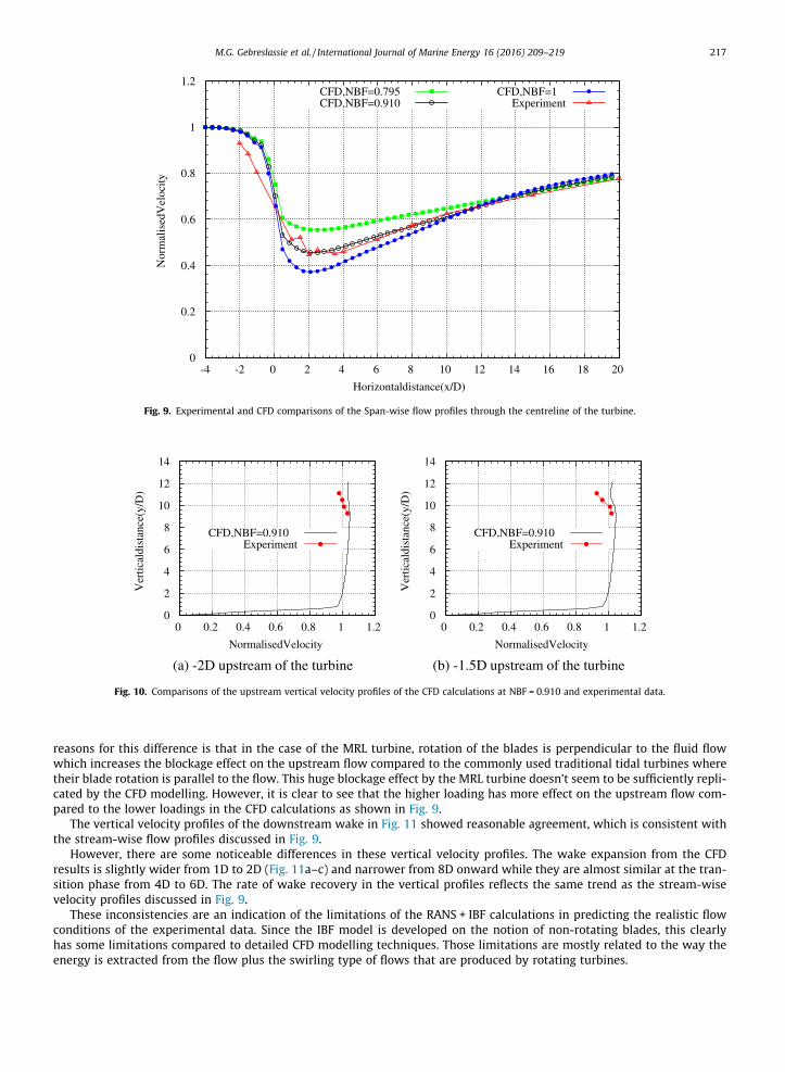
Fig. 9. Experimental and CFD comparisons of the Span-wise flow profiles through the centreline of the turbine.
Experiment
(a) -2D upstream of the turbine
Experiment
(b) -1.5D upstream of the turbine
Fig. 10. Comparisons of the upstream vertical velocity profiles of the CFD calculations at NBF = 0.910 and experimental data.
M.G. Gebreslassie et al. / International Journal of Marine Energy 16 (2016) 209–219 217
reasons for this difference is that in the case of the MRL turbine, rotation of the blades is perpendicular to the fluid flowwhich increases the blockage effect on the upstream flow compared to the commonly used traditional tidal turbines wheretheir blade rotation is parallel to the flow. This huge blockage effect by the MRL turbine doesn’t seem to be sufficiently repli-cated by the CFD modelling. However, it is clear to see that the higher loading has more effect on the upstream flow com-pared to the lower loadings in the CFD calculations as shown in Fig. 9.
The vertical velocity profiles of the downstream wake in Fig. 11 showed reasonable agreement, which is consistent withthe stream-wise flow profiles discussed in Fig. 9.
However, there are some noticeable differences in these vertical velocity profiles. The wake expansion from the CFDresults is slightly wider from 1D to 2D (Fig. 11a–c) and narrower from 8D onward while they are almost similar at the tran-sition phase from 4D to 6D. The rate of wake recovery in the vertical profiles reflects the same trend as the stream-wisevelocity profiles discussed in Fig. 9.
These inconsistencies are an indication of the limitations of the RANS + IBF calculations in predicting the realistic flowconditions of the experimental data. Since the IBF model is developed on the notion of non-rotating blades, this clearlyhas some limitations compared to detailed CFD modelling techniques. Those limitations are mostly related to the way theenergy is extracted from the flow plus the swirling type of flows that are produced by rotating turbines.

Experiment
(a) 1D
Experiment
(b) 2D
Experiment
(c) 4D
Experiment
(d) 8D
Experiment
(e) 15D
Experiment
(f) 20D
Fig. 11. Comparisons of the wake vertical velocity profiles of the CFD calculations at NBF = 0.910 and experimental data.
218 M.G. Gebreslassie et al. / International Journal of Marine Energy 16 (2016) 209–219
3.3. Execution time of the simulations
The simulations were carried out using an 8 GB machine. Detailed 2D CFD simulations of the MRL turbine using dynamicsliding mesh takes more than 240 h for 20 revolutions of the blades (to obtain fully developed wake structure). The 2D sim-ulations of the MRL turbine was conducted as part of the EPSRC funded project but was computationally very expensive andthus 3D simulations was not conducted. In the case of the IBF model, simulation of a single turbine takes about 8 h to obtainfully developed wake structures which is much cheaper than the detailed CFD model even for 3D CFD simulations. Though itis obvious that the two are not directly comparable, it is clear to see the magnitude of their difference in the simulation time.Practically 2D simulation is computationally cheaper than 3D simulations but still the 2D simulations using dynamic slidingmesh method is 30 times higher than the 3D simulations using the IBF model. This is because CFD model with a physicalpresence of the blades can significantly increase the computational power due to the treatment involved to resolve the flow

M.G. Gebreslassie et al. / International Journal of Marine Energy 16 (2016) 209–219 219
on the surface of the blades. However, in the case of the IBF model, there is no physical presence of the blades as discussed inthe previous sections which resulted in cheaper computational cost.
4. Conclusion
The empirically-based IBF model developed based on the concept of the actuator disk method was calibrated against flowcharacteristics data for an MRL turbine obtained from experiment in the IFREMERWave-Current circulating tank, France. Themodel was found to performwell, although we recognise that it does not necessarily fully reproduce all the large scale deter-ministic flow patterns in the way that a dynamic blade motion simulation would do. This was reflected in some of the incon-sistency observed on the flow profiles between the CFD and experimental data. However such a blade motion simulationwould be in the orders of magnitude more expensive to calculate, and the IBF method is thus computationally cheap enoughto allowmultiple turbine simulations to be run. Therefore, considering the complexity and computational cost of modelling adetailed blade motion the limitations of the IBF model are acceptable and will be useful especially for optimisation of arraysof devices where there is a significant computational demand.
Acknowledgement
We would like to thank EPSRC for providing the funding under project number EP/J010138/1, as part of the SupergenMarine research program and the IFREMER personnel of Boulogne-sur-Mer for their assistance and advice during the exper-imental trials.
References
[1] S. Gant, T. Stallard, Modelling a tidal turbine in unsteady flow, in: Proceedings of the Eighteenth (2008) International Offshore and Polar EngineeringConference, 2008, pp. 473–479.
[2] M.E. Harrison, W.M.J. Batten, L.E. Myers, A.S. Bahaj, Comparison between CFD simulations and experiments for predicting the far wake of horizontalaxis tidal turbines, Renewable Power Gener. IET 4 (6) (2010) 613–627.
[3] R. Mikkelsen, Actuator disc methods applied to wind turbines, Technical University of Denmark, 2003 (Ph.D. thesis).[4] B. Sanderse, Aerodynamics of wind turbine wakes, Energy Research Center of the Netherlands (ECN), ECN-E–09-016, Petten, The Netherlands, Tech.
Rep, 2009.[5] C.S.K. Belloni, R.H.J. Willden, Flow field and performance analysis of bidirectional and open-centre ducted tidal turbines, in: 9th European Wave and
Tidal Energy Conference, 2011.[6] A.J. MacLeod, S. Barnes, K.G. Rados, I.G. Bryden, Wake effects in tidal current turbine farms, in: International Conference on Marine Renewable Energy-
Conference Proceedings, 2002, pp. 49–53.[7] X. Sun, J.P. Chick, I.G. Bryden, Laboratory-scale simulation of energy extraction from tidal currents, Renewable Energy 33 (6) (2008) 1267–1274.[8] William M.J. Batten, M.E. Harrison, A.S. Bahaj, Accuracy of the actuator disc-rans approach for predicting the performance and wake of tidal turbines,
Philos. Trans. R. Soc. London A 371 (1985) (2013) 20120293.[9] A.P. Janssen, M.R. Belmont, Initial research phase of MRL turbine, Technical report, Technical Report N0:MO 562L, 2009.[10] Mulualem G. Gebreslassie, Gavin R. Tabor, Michael R. Belmont, CFD simulations for sensitivity analysis of different parameters to the wake
characteristics of tidal turbine, Open J. Fluid Dyn. 2 (2012) 56.[11] Mulualem G. Gebreslassie, Gavin R. Tabor, Michael R. Belmont, Investigation of the performance of a staggered configuration of tidal turbines using
CFD, Renewable Energy 80 (2015) 690–698.[12] Mulualem G. Gebreslassie, Gavin R. Tabor, Michael R. Belmont, Numerical simulation of a new type of cross flow tidal turbine using openfoam–part ii:
Investigation of turbine-to-turbine interaction, Renewable Energy 50 (2013) 1005–1013.[13] M.E. Harrison, W.M.J. Batten, A.S. Bahaj, A blade element actuator disc approach applied to tidal stream turbines, in: OCEANS 2010, IEEE, 2010, pp. 1–8.[14] F.R. Menter, M. Kuntz, R. Langtry, Ten years of industrial experience with the SST turbulence model, Turbul. Heat Mass Transfer 4 (1) (2003).[15] H. Schlichting, K. Gersten, Boundary-Layer Theory, Springer, 2004.[16] F.M. White, Viscous Fluid Flow, vol. 66, McGraw-Hill, New York, 1991.[17] W.M.J. Batten, A.S. Bahaj, A.F. Molland, J.R. Chaplin, The prediction of the hydrodynamic performance of marine current turbines, Renewable Energy 33
(5) (2008) 1085–1096.[18] H. Jasak, A. Jemcov, Z. Tukovic, Openfoam: A c++ library for complex physics simulations, in: International Workshop on Coupled Methods in
Numerical Dynamics, IUC, Dubrovnik, Croatia, 2007.[19] H. Jasak, Multi-physics simulations in continuum mechanics, in: Proceedings of 5th International Conference of Croatian Society of Mechanics, Trogir,
page, 2006.[20] Henry G. Weller, G. Tabor, Hrvoje. Jasak, C. Fureby, A tensorial approach to computational continuum mechanics using object-oriented techniques,
Comput. Phys. 12 (6) (1998) 620–631.[21] G.T. Houlsby, S. Draper, M.L.G. Oldfield, et al, Application of linear momentum actuator disc theory to open channel flow, Report no. OUEL 2296 (08)
(2008).[22] M.E. Harrison, The accuracy of the actuator disc-RANS model for predicting the performance and far wake of a horizontal axis tidal stream turbine,
University of Southampton, 2011 (Ph.D. thesis).[23] Mulualem G. Gebreslassie, Simplified CFD modelling of tidal turbines for exploring arrays of devices, University of Exeter, 2012 (Ph.D. thesis).