Embed Size (px)
Citation preview

International Journal of Mining Science and Technology 24 (2014) 871–881
Contents lists available at ScienceDirect
International Journal of Mining Science and Technology
journal homepage: www.elsevier .com/locate / i jmst
Distinct element modelling of fracture plan control in continuumand jointed rock mass in presplitting method of surface mining
http://dx.doi.org/10.1016/j.ijmst.2014.10.0222095-2686/� 2014 Published by Elsevier B.V. on behalf of China University of Mining & Technology.
⇑ Corresponding author. Tel.: +98 61451541001.E-mail address: [email protected] (M. Sharafisafa).
Sharafisafa Mansour a,⇑, Aliabadian Zeinab a, Alizadeh Rezvan b, Mortazavi Ali a
a Department of Mining, Metallurgy and Petroleum Engineering, Amirkabir University of Technology, Tehran, Iranb Department of Mining Engineering, Sahand University of Technology, Tabriz, Iran
a r t i c l e i n f o
Article history:Received 17 February 2014Received in revised form 20 April 2014Accepted 22 June 2014Available online 15 November 2014
Keywords:Controlled blastingPresplitting methodContinuum and jointed rock massDistinct element modelling
a b s t r a c t
Controlled blasting techniques are used to control overbreak and to aid in the stability of the remainingrock formation. Presplitting is one of the most common methods which is used in many open pit miningand surface blast design. The purpose of presplitting is to form a fracture plane across which the radialcracks from the production blast cannot travel. The purpose of this study is to investigate of effect of pre-splitting on the generation of a smooth wall in continuum and jointed rock mass. The 2D distinct elementcode was used to simulate the presplitting in a rock slope. The blast load history as a function of time wasapplied to the inner wall of each blasthole. Important parameters that were considered in the analysiswere stress tensor and fracturing pattern. The blast loading magnitude and blasthole spacing and jointingpattern were found to be very significant in the final results.
� 2014 Published by Elsevier B.V. on behalf of China University of Mining & Technology.
1. Introduction
Drilling and blasting continues to be an important method ofblock production and block splitting. Drill and blast techniquehas a disadvantage that sometimes it produces cracks in uncon-trolled manner and also produces micro cracks in the block as wellas in remaining rock, if not carefully carried out. Recovery by thismethod is low as compared to other methods. Therefore, attemptshave been made to develop controlled growth of crack in thedesired direction. The control of fractures in undamaged brittlematerials is of considerable interest in several practical applica-tions including rock fragmentation and overbreak control in min-ing [1–3]. One way of achieving controlled crack growth alongspecific directions and inhibit growth along other directions is togenerate stress concentrations along those preferred directions.Several researchers have suggested a number of methods forachieving fracture plane control by means of blasting. Fourneyet al. suggested a blasting method which utilizes a ligamentedsplit-tube charge holder [4]. Nakagawa et al. examined the effec-tiveness of the guide hole technique by model experiments usingacrylic resin plates and concrete blocks having a charge hole andcircular guide holes [5]. Katsuyama et al. suggested a controlledblasting method using a sleeve with slits in a borehole [6].
Mohanty suggested a fracture plane control technique usingsatellite holes on either side of the central pressurized hole, anddemonstrated its use through laboratory experiments and field tri-als in rock [7–8]. Nakamura et al. suggested a new blasting methodfor achieving crack control by utilizing a charge holder with twowedge-shaped air cavities [9]. Ma and An conducted a numericalstudy to investigate the effective parameters on propagation suchas nearby to free face, pre-existing stresses as well as notchedand guide hole and pre-split charge holders. They concluded thatwhen the pre-existing joint is parallel to the free face, the blockbehind the joint will be well fragmented due to the free face. Whenthe pre-existing joint is normal to the free face, there is no damagein the block behind the joint. It justifies the pre-splitting technique,which is designed to prevent overbreak. They also showed thatcharge holder is effective in controlling the initiation andpropagation of fractures. Two-slit charge holder can be used in pre-splitting operation, while three-slit charge holder can be applied insmooth blasting where more fragmentation is desired at one sideof the fractured plane [10].
Nakamura performed model experiments to examine the effec-tiveness of the guide hole with notches [11]. Cho et al. performedexperiments using a notched charge hole to visualize fracturingand gas flow due to detonation of explosives [12]. Recently modelexperiments using PMMA specimens and electric detonators werecarried out to observe the propagation of cracks between twocharge holes in blasting by Nakamura et al [13]. The applicabilityof the guide hole method using a circular hole having two notches
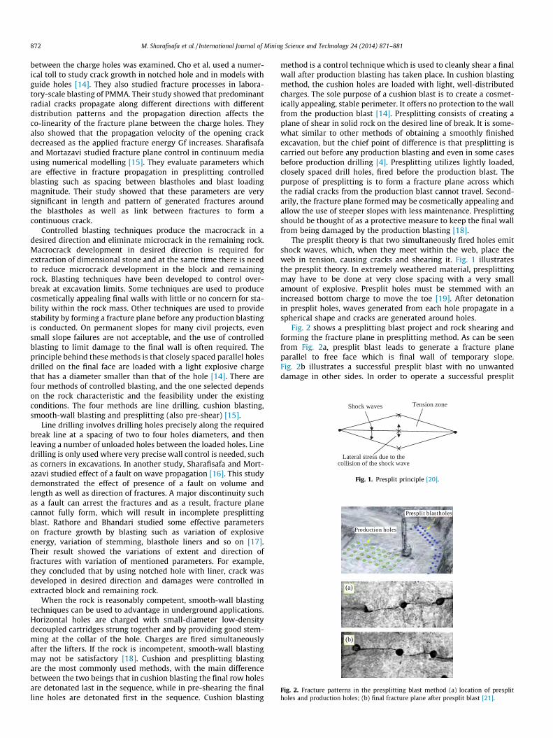
Tension zoneShock waves
Lateral stress due to the collision of the shock wave
Fig. 1. Presplit principle [20].
Presplit blastholes
Production holes
(a)
(b)
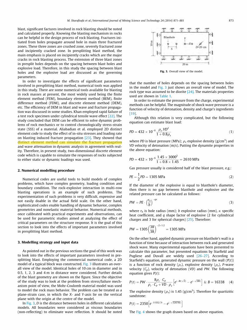
Fig. 2. Fracture patterns in the presplitting blast method (a) location of presplitholes and production holes; (b) final fracture plane after presplit blast [21].
872 M. Sharafisafa et al. / International Journal of Mining Science and Technology 24 (2014) 871–881
between the charge holes was examined. Cho et al. used a numer-ical toll to study crack growth in notched hole and in models withguide holes [14]. They also studied fracture processes in labora-tory-scale blasting of PMMA. Their study showed that predominantradial cracks propagate along different directions with differentdistribution patterns and the propagation direction affects theco-linearity of the fracture plane between the charge holes. Theyalso showed that the propagation velocity of the opening crackdecreased as the applied fracture energy Gf increases. Sharafisafaand Mortazavi studied fracture plane control in continuum mediausing numerical modelling [15]. They evaluate parameters whichare effective in fracture propagation in presplitting controlledblasting such as spacing between blastholes and blast loadingmagnitude. Their study showed that these parameters are verysignificant in length and pattern of generated fractures aroundthe blastholes as well as link between fractures to form acontinuous crack.
Controlled blasting techniques produce the macrocrack in adesired direction and eliminate microcrack in the remaining rock.Macrocrack development in desired direction is required forextraction of dimensional stone and at the same time there is needto reduce microcrack development in the block and remainingrock. Blasting techniques have been developed to control over-break at excavation limits. Some techniques are used to producecosmetically appealing final walls with little or no concern for sta-bility within the rock mass. Other techniques are used to providestability by forming a fracture plane before any production blastingis conducted. On permanent slopes for many civil projects, evensmall slope failures are not acceptable, and the use of controlledblasting to limit damage to the final wall is often required. Theprinciple behind these methods is that closely spaced parallel holesdrilled on the final face are loaded with a light explosive chargethat has a diameter smaller than that of the hole [14]. There arefour methods of controlled blasting, and the one selected dependson the rock characteristic and the feasibility under the existingconditions. The four methods are line drilling, cushion blasting,smooth-wall blasting and presplitting (also pre-shear) [15].
Line drilling involves drilling holes precisely along the requiredbreak line at a spacing of two to four holes diameters, and thenleaving a number of unloaded holes between the loaded holes. Linedrilling is only used where very precise wall control is needed, suchas corners in excavations. In another study, Sharafisafa and Mort-azavi studied effect of a fault on wave propagation [16]. This studydemonstrated the effect of presence of a fault on volume andlength as well as direction of fractures. A major discontinuity suchas a fault can arrest the fractures and as a result, fracture planecannot fully form, which will result in incomplete presplittingblast. Rathore and Bhandari studied some effective parameterson fracture growth by blasting such as variation of explosiveenergy, variation of stemming, blasthole liners and so on [17].Their result showed the variations of extent and direction offractures with variation of mentioned parameters. For example,they concluded that by using notched hole with liner, crack wasdeveloped in desired direction and damages were controlled inextracted block and remaining rock.
When the rock is reasonably competent, smooth-wall blastingtechniques can be used to advantage in underground applications.Horizontal holes are charged with small-diameter low-densitydecoupled cartridges strung together and by providing good stem-ming at the collar of the hole. Charges are fired simultaneouslyafter the lifters. If the rock is incompetent, smooth-wall blastingmay not be satisfactory [18]. Cushion and presplitting blastingare the most commonly used methods, with the main differencebetween the two beings that in cushion blasting the final row holesare detonated last in the sequence, while in pre-shearing the finalline holes are detonated first in the sequence. Cushion blasting
method is a control technique which is used to cleanly shear a finalwall after production blasting has taken place. In cushion blastingmethod, the cushion holes are loaded with light, well-distributedcharges. The sole purpose of a cushion blast is to create a cosmet-ically appealing, stable perimeter. It offers no protection to the wallfrom the production blast [14]. Presplitting consists of creating aplane of shear in solid rock on the desired line of break. It is some-what similar to other methods of obtaining a smoothly finishedexcavation, but the chief point of difference is that presplitting iscarried out before any production blasting and even in some casesbefore production drilling [4]. Presplitting utilizes lightly loaded,closely spaced drill holes, fired before the production blast. Thepurpose of presplitting is to form a fracture plane across whichthe radial cracks from the production blast cannot travel. Second-arily, the fracture plane formed may be cosmetically appealing andallow the use of steeper slopes with less maintenance. Presplittingshould be thought of as a protective measure to keep the final wallfrom being damaged by the production blasting [18].
The presplit theory is that two simultaneously fired holes emitshock waves, which, when they meet within the web, place theweb in tension, causing cracks and shearing it. Fig. 1 illustratesthe presplit theory. In extremely weathered material, presplittingmay have to be done at very close spacing with a very smallamount of explosive. Presplit holes must be stemmed with anincreased bottom charge to move the toe [19]. After detonationin presplit holes, waves generated from each hole propagate in aspherical shape and cracks are generated around holes.
Fig. 2 shows a presplitting blast project and rock shearing andforming the fracture plane in presplitting method. As can be seenfrom Fig. 2a, presplit blast leads to generate a fracture planeparallel to free face which is final wall of temporary slope.Fig. 2b illustrates a successful presplit blast with no unwanteddamage in other sides. In order to operate a successful presplit
S
Y
XD=20 cm
Blasthole
20 m
10m
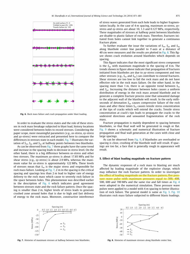
Fig. 3. Overall view of the model.
M. Sharafisafa et al. / International Journal of Mining Science and Technology 24 (2014) 871–881 873
blast, significant factures involved in rock blasting should be notedand calculated properly. Knowing the blasting mechanism in rockscan be helpful in the design process of rock blasting. Fractures ini-tiated from holes propagate around hole in main three fracturedzones. These three zones are crushed zone, severely fractured zoneand incipiently cracked zone. In presplitting blast method, themain emphasis is placed on incipiently cracks which are the majorcracks in rock blasting process. The extension of three blast zonesin presplit holes depends on the spacing between blast holes andexplosive load. Therefore, in this study the spacing between blastholes and the explosive load are discussed as the governingparameters.
In order to investigate the effects of significant parametersinvolved in presplitting blast method, numerical tools was appliedin this study. There are some numerical tools available for blastingin rock masses at present, the most widely used being the finiteelement method (FEM), boundary element method (BEM), finitedifference method (FDM), and discrete element method (DEM),etc. The efficiency of DEM in blast and wave and fracture propaga-tion was discussed in some studies. Khan employed rapid failure ofa test rock specimen under cylindrical tensile wave effect [22]. Thestudy concluded that DEM can be efficient to solve dynamic prob-lems of rock mechanics or to control chronologically stress-strainstate (SSS) of a material. Aliabadian et al. employed 2D distinctelement code to study the effect of in-situ stresses and loading rateon blasting induced fracture propagation [23]. They showed thatdistinct element method can simulate the fracture propagationand wave attenuation in dynamic analysis in agreement with real-ity. Therefore, in present study, two-dimensional discrete elementcode which is capable to simulate the responses of rocks subjectedto either static or dynamic loadings was used.
2. Numerical modelling procedure
Numerical codes are useful tools to build models of complexproblems, which have complex geometry, loading condition andboundary condition. The rock-explosive interaction in multi-rowblasting operations is an example of such problems. Theexperimentation of such problems is very difficult, expensive andnot easily doable in the actual field scale. On the other hand,sophisticated codes enable handling of dynamic behavior, complexgeometries and nonelastic material behavior. Numerical methods,once calibrated with practical experiments and observations, canbe used for parametric studies aimed at analyzing the effect ofcritical parameters on the structure response. It is the goal of thissection to look into the effects of important parameters involvedin presplitting blast method.
3. Modelling strategy and input data
As pointed out in the previous sections the goal of this work wasto look into the effects of important parameters involved in pre-splitting blast. Employing the commercial numerical code, a 2Dmodel of a typical block was constructed. Fig. 3 illustrates an over-all view of the model. Identical holes of 10 cm in diameter and in0.5, 1, 2, 3 and 4 m in distance were considered. Further detailsof the blast geometry are shown on the figure. Since the objectiveof the study was to look at the problem from stress/failure mech-anism point of view, the Mohr-Coulomb material model was usedto model the rock mass behavior. The problem can be treated as aplane-strain case, in which the X- and Y-axis lie on the verticalplane with the origin at the centre of the model.
In Fig. 3, D is the distance between holes in different calculationmodels. All boundaries were considered as viscous boundaries(non-reflecting) to eliminate wave reflection. It should be noted
that the number of holes depends on the spacing between holesin the model and Fig. 3 just shows an overall view of model. Therock type was assumed to be diorite [24]. The materials propertiesused are shown in Table 1.
In order to estimate the pressure from the charge, experimentalmethods can be helpful. The magnitude of shock wave pressure is afunction of velocity of detonation, density and charge’s ingredients[19].
Although this relation is very complicated, but the followingequation can estimate blast load:
PD ¼ 432� 10�6 qe:VD2
1þ 0:8qeð1Þ
where PD is blast pressure (MPa); qe explosive density (g/cm3) andVD velocity of detonation (m/s). Putting the dynamite properties inthe above equation:
PD ¼ 432� 10�6 1:45� 30002
1þ 0:8� 1:45¼ 2610 MPa
Gas pressure usually is considered half of the blast pressure, e.g.:
PE ¼ 12
PD ¼ 1305 MPa ð2Þ
If the diameter of the explosive is equal to blasthole’s diameter,then there is no gap between blasthole and explosive and therelated pressure can be calculated as follows:
PW ¼ PE � rh
b
� ��qjð3Þ
where rh is hole radius (mm); b explosive radius (mm), j specificheat coefficient, and q shape factor of explosive (2 for cylindricalcharges and 3 for spherical charges) [25]. Therefore:
PW ¼ 13053838
� ��2�1:2
¼ 1305 MPa
On the other hand, applied dynamic pressure on blasthole’s wall is afunction of time because of interaction between rock and generatedshock wave. Many experimental equations have been presented tocalculate this parameter, but presented equations by Starfield andPugliese and Duvall are widely used [26–27]. According toStarfield’s equation, generated dynamic pressure on the wall (P(t))is a function of rock density (qr), explosive density (qe), P-wavevelocity (Cp), velocity of detonation (VD) and PW. The followingequation gives P(t):
PðtÞ ¼ PW � 8qr � Cp
qr � Cp þ VD � qeeð�Bt=
ffiffi2pÞ � eð�
ffiffiffiffiffi2Btp
Þh i
& B ¼ 16338 ð4Þ
The explosive density (qe) is 1.45 (g/cm3). Therefore for quartiziticsandstone:
PðtÞ ¼ 2350 e�11552:7t � eð�ffiffiffiffiffiffiffiffiffiffiffi32676tp
Þh i
The Fig. 4 shows the graph drawn based on above equation.

Table 1Rock mass properties used as input.
Parameter Density (kg/m3) Bulk modulus (GPa) Shear modulus (GPa) Tensile strength (MPa) Shear strength (MPa)
Value 3160 52.4 39.6 18.8 44.16
Time (s×10-4)
Pres
sure
(MPa
)
0.5 1.0 1.5 2.0 2.5 3.00
900800700600500400300200100
Fig. 4. Dynamic pressure applying on the blastholes’s wall.
874 M. Sharafisafa et al. / International Journal of Mining Science and Technology 24 (2014) 871–881
As can be seen from Fig. 4, the peak pressure is about 820 MPa.It was assumed that the explosive is of a shocky type and deliversmost of its energy in the form of stress wave. It should be notedthat the shape of stress pulse presented in Fig. 4 was used in firststep of calculations which were conducted to investigate thespacing effect between holes. The second step of calculations wasevaluating the effect of the amount of pressure applied to holeswith the same rise and fall times. In order to better understandingof wave propagation in presplitting method, plasticity indicatorsand velocity vectors were monitored as a function of stress wavepropagation/collision in each model and for comparing the results,the monitored parameters were plotted at the same time. More-over, history locations were considered at points between holesas well as in locations lying parallel to Y-axis around each hole.
Fig. 5. Illustration of stress wave front at 0.2 ms (S: Spacing).
4. Numerical simulation results of spacing effect on fractureplane creation
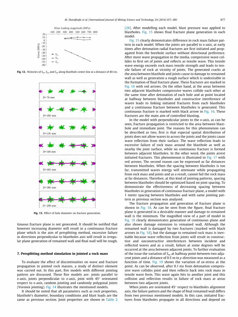
As outlined earlier, five models consist of five differentdistances between holes (S = 0.5, 1, 2, 3 and 4 m) were conducted.All models have the same dimensions in width and length as pre-sented in Fig. 3. Main difference in the models is in number of holeswhich depends on the distance between holes. After static calcula-tion, dynamic analysis of the applying the blast load on blasthole’swall was conducted. Fig. 5 illustrates velocity vectors as wave frontpropagating in the rock mass in five models mentioned earlier. Ascan be seen in Fig. 5, each model has different trend of wave prop-agation and collision from others. In the cases of 0.5, 1 and 2 m in S,before 0.2 ms the wave fronts from each hole collide one anotherand complicated interaction between wave fronts starts, whereasin the cases of 3 and 4 m in S, wave fronts have not collided twowave fronts raised from adjacent blastholes. These interactionsbetween wave fronts lead to different fracture pattern of rock massin each model. Fig. 6 illustrates rock failure and crack propagationin 5 mentioned model.
As can be seen from Fig. 6, fracturing in each model has differ-ent trend from others which indicates effect of different distancebetween holes. As mentioned earlier in Section 1, depends on dis-tance between holes, different types of blast induced fracturing aregenerated around holes. Once the spacing is too close, numerousfractures link in the plane between holes and when the blast isexcavated the material between holes will fall out leaving halfcasts protruding from the final wall. Moreover, the most yieldedzones are crushed zones and other types of fractures such asseverely fractured zone and incipiently cracked zone are notcreated. This fracturing pattern indicates less damage to adjacent
walls and forming a straight fracture plane. This process can beseen in Fig. 6 and in models with 0.5 and 1 m in spacing. Increasingin spacing leads to generate longer fractures as well as decreasingcrushed zone’s area. If spacing is more than 2 m and less than 4 m,severely fractured zone will be dominated fracture zone andcrushed zone will be restricted just in close distances around holes.These fractures link in the plane between holes and lead to gener-ate a fracture plane which is the desired fracture plane. On theother hand, incipiently fractures generated from cracked zone aretoo short to form linked cracks which means in these spacingswave fronts interference is just able to generate short cracks.Furthermore, fractures initiated from crushed zone lead to damageto adjacent walls. Therefore, if spacings are too far, a face that isgenerally rough in appearance will result. In the cases with verylarge distance between holes, wave front generated from each holeacts similar to an individual blast in rock mass and complete frac-ture process zone around blastholes is generated which consists ofcrushed zone, severely fractured zone and incipiently crackedzone. This phenomenon means there is no constructive or uncon-structive interference between stress wave fronts and rock failureis limited just around blastholes. Therefore, fractures initiated fromblastholes do not link together which means there is no fractureplane and applicability of presplit blast is not fulfilled. As can beobserved from Fig. 6 in the case of S = 4 m, fracture plane has notgenerated and just longer fractures propagate around blasthole.
At yield surface (*) 0Yielded in past (X) 1395Tensile failure (o) 193
Fig. 6. Rock mass failure and crack propagation under blast loading.
M. Sharafisafa et al. / International Journal of Mining Science and Technology 24 (2014) 871–881 875
In order to evaluate the stress states and the role of these stres-ses in rock mass breakage subjected to blast load, history locationswere considered between holes to record stresses. Considering thepaper scope, more meaningful parameters (e.g., xx-stress, xy-stressand yy-stress) were extracted and presented here to compare thedifferences in stresses state in each model. Fig. 7 illustrates the var-iation of Sxx, Syy and Sxy at halfway points between two blastholes.
As can be observed from Fig. 7 three graphs have the same trendand increase in the spacing leads to decrease in stress level. On theother hand, there is a big difference between xx-stress and othertwo stresses. The maximum yy-stress is about 17.85 MPa and forshear stress (e.g., xy-stress) is about 2.9 MPa, whereas the maxi-mum value for xx-stress is approximately 122 MPa. These levelsof stresses mean that Sxx is the major stress and responsible forrock mass failure. Looking at Fig. 7, 2 m in the spacing is the criticalspacing and spacings less than 2 m lead to higher rate of energydelivery to the rock mass which cause to severely rock failure inthe space between holes. This phenomenon was described earlierin the description of Fig. 6 which indicates good agreementbetween stresses state and the rock failure pattern. Once the spac-ing is smaller than 2 m, higher levels of stress leads to generatecrushed zone around holes that is due to high and fast deliveryof energy to the rock mass. Moreover, constructive interference
Sxx
Stre
ss (M
Pa)
Spacing (m)
Syy
Sxy
0.5 1.0 1.5 2.0 2.5 3.0 3.5 4.50 4.0
-25
-50
-75
-100
-125
-150
Fig. 7. Histories of maximum stresses at halfway between two blastholes.
of stress waves generated from each hole leads to higher fragmen-tation locally. In the case of 4 m spacing, maximum xx-stress, yy-stress and xy-stress are about 10, 1.3 and 0.127 MPa, respectively.These magnitudes of stresses at halfway point between blastholesare disable to plastic failure of rock mass. Therefore, fractures ini-tiated from holes cannot link together to generate a continuousfracture plane.
To further evaluate the issue the variations of Sxx, Syy and Sxy
along blasthole center line parallel to Y-axis at a distance of40 cm were measures and the results are plotted in Fig. 8. This fig-ure shows crack evolution around blastholes which depends onspacing.
This figure indicates that the most significant stress componentis the Syy with maximum magnitude in the spacing of 4 m. Thetrends shown in figure above indicate that propagation of fracturesinitiated from blastholes are due to yy-stress component and twoother stresses (e.g., Sxx and Sxy) can contribute to extend fractures.Shear stresses are too low to fail the rock mass and do not haveeffective role in the rock mass failure. On the other hand, in thespacing more than 1 m, there is an opposite trend between Sxx
and Syy. Increasing the distance between holes causes a uniformdistribution of energy in the rock mass around blasthole and togenerate a complete fracture process zone that unwanted damageto the adjacent wall of the blasthole will result. In the early milli-seconds of detonation Syy causes compressive failure of the rockmass and after these times Sxx causes tensile stress concentrationat the tips of cracks which will extend the cracks. Tensile stressconcentration at crack’s tips leads to propagate the cracks to theundesired directions and unwanted fragmentation of the rockmass.
Fracture propagation is mainly dependent to spacing betweenblastholes, so that final wall will be generated in rough or flat.Fig. 9 shows a schematic and numerical illustration of fracturepropagation and final wall generation at the cases with close andlarge spacings.
As can be observed from Fig. 9, if blastholes are overloaded orspacing is close, crushing of the blasthole wall will result. If spac-ings are too far, a face that is generally rough in appearance willresult.
5. Effect of blast loading magnitude on fracture pattern
The dynamic responses of a rock mass to blasting are muchaffected by loading magnitude of the explosive charge, whichmay influence the rock fracture pattern. In order to investigatethe effect of loading magnitude on the fracture pattern, five pres-sure wave pulse with maximum pressures equal to 300, 400,500, 600 and 700 MPa and the same rise and fall times as Fig. 4were adopted in the numerical simulation. These pressure wavepulses were applied to a model with 4 m spacing to better illustra-tion of rock failure. The general model is same as Fig. 3. Fig. 10illustrates rock mass failure subjected to different blasts loadings.
Spacing (m)
Stre
ss(M
Pa) 0
201.0 1.5 2.0 2.5 3.0 3.5 4.54.00.5
10
-10
-20
-30-40-50
SxxSyy
Sxy
Fig. 8. Histories of maximum stresses along blasthole center line.

Fig. 9. Generation of final wall at close and large spacing.
Fig. 10. Illustration of rock failure subjected to five different blasts loading.
Blast loading magnitude (MPa) 100 200 300 400 500 600 7000 800
0
4
-4
-8
-12
-16
Stre
ss(M
Pa)
Sxx
Syy
Sxy
Fig. 11. Variation of Sxx, Syy and Sxy at halfway point between blastholes.
876 M. Sharafisafa et al. / International Journal of Mining Science and Technology 24 (2014) 871–881
As can be seen from Fig. 10, a higher loading magnitude increasesthe number of fractures and causes the intense stress releasearound the running fractures.
When the blast loading is less than 500 MPa, fractures gener-ated from the blastholes cannot link together to generate a contin-uous fracture plane and fracture pattern is similar to blasting in asingle blasthole. When blast loading exceeds 500 MPa, construc-tive interference of stress waves generated from each hole leadsto higher fragmentation locally. This phenomenon occurs in pointsbetween holes and leads to link incipiently fractures which createfinal fracture plane. As can be seen from Fig. 9 in the case of600 MPa, fractures are not linked together entirely and linked frac-tures have not generated a straight line which is desired. When theblast loading exceeds 600 MPa and reaches to 700 MPa, a perfectfracture plane is generated that is main scope of presplit blastingperformance. It should be noted that intensive blast load leads togenerate more fractures around hole which can damage rock massaround blasthole in unwanted directions. In order to investigatethe stresses states at the points between holes, history points torecord stresses were considered at these points. Fig. 11 shows
the variation of Sxx, Syy and Sxy at halfway points between twoblastholes.
As illustrated in Fig. 11, there is a meaningful differencebetween Sxx and other two stresses. With increasing the appliedpressure on blasthole’s wall, the xx-stress increase gradually. Thered graph shows two trends. Firs trend begins at 7.65 and endsat 13.7 MPa, and the second trend is between 13.7 and 16.3 MPa.In the first trend rock failure does not occur in this point, whereasin the second trend rock failure occurs. This means that to generatea continuous fracture, 500 MPa is critical loading and blast loadingshould be increased to more than this value. On the other hand,yy-stress and xy-stress do not have significant effect on rock failurein this point which indicates that these stresses do not contributeto link fractures between holes.
Fig. 12 illustrates the variation of Sxx, Syy and Sxy at a point alongblasthole center line parallel to Y-axis at a distance of 40 cm. In thisfigure it is clear that at points along to blasthole center, rock failureis due to high values of yy-stress. There is a dramatic increase inthe magnitude of yy-stress with increasing the blast loading. Itmeans that yy-stress is responsible for creating fractures in direc-tions parallel to y-axis. Therefore, mainly the yy-stress componentleads to damage to rock mass in undesired directions. On the otherhand, xx-stress and xy-stress have approximately remained con-stant and maximum value of xx-stress and xy-stress are about 10and 5.6 MPa, respectively.
6. Blasthole diameter effect on generation of fracture plane
Hole diameter is one of most important parameter whicheffects on final fracture plane generation. To study this parameteron fracture propagation, seven models with 76, 100, 120, 140, 160,180 and 200 mm in diameter of blastholes were built. Then, blastload was applied to blastholes and the results were extracted.Fig. 13 illustrates the fracture pattern at each model.
As can be seen from Fig. 13, increasing the diameter lead toincrease in fracture extent. With a diameter of 200 mm, final frac-ture plane is generated, while with diameters lower than 200 mm,fracture generation and inking between fractures is local and con-
Blast loading magnitude (MPa) 100 200 300 400 500 600 700 800
Stre
ss(M
Pa)
0
2010
-10-20-30-40-50-60-70-80
Sxx
Syy
Sxy
Fig. 12. Histories of Sxx, Syy and Sxy along blasthole center line at a distance of 40 cm.
D= 76 mm
D= 100 mm
D= 120 mm
D= 140 mm
D= 160 mm
D= 180 mm
D= 200 mm
Fig. 13. Effect of hole diameter on fracture generation.
M. Sharafisafa et al. / International Journal of Mining Science and Technology 24 (2014) 871–881 877
tinuous fracture plane is not generated. It should be notified thathowever increasing diameter will result in a continuous fractureplane which is the aim of presplitting method, excessive failurein directions perpendicular to blastholes axis will result in irregu-lar plane generation of remained wall and final wall will be rough.
7. Presplitting method simulation in jointed a rock mass
To evaluate the effect of discontinuities on wave and fracturepropagation in jointed rock masses, a study of distinct elementwas carried out. In this part, five models with different jointingpattern are discussed. These five models are: joints parallel tox-axis, joints perpendicular to x-axis, joint with 45� orientatedrespect to x-axis, random jointing and randomly polygonal joints(Voronoi jointing). Fig. 14 illustrates the mentioned models.
It should be noted that all parameters such as rock properties,blasthole’s diameter, boundary conditions and blast loads are thesame as previous section. Joint properties are shown in Table 2
[28]. After modelling each model, blast pressure was applied toblastholes. Fig. 15 shows final fracture plane generation in eachmodel.
Fig. 15 clearly demonstrates difference in rock mass failure pat-tern in each model. When the joints are parallel to x-axis, at earlytimes after detonation radial fractures are first initiated and prop-agated from the borehole surface without directional preference.After more wave propagation in the media, compressive wave col-lides to first set of joints and reflects as tensile wave. This tensilewave energy exceeds rock mass tensile strength and leads to ten-sile failure of rock at vicinity of joints. The generated cracks atthe area between blasthole and joints cause to damage to remainedwall as well as generation a rough surface which is undesirable inthe formation of final fracture plane. These fractures are marked inFig. 16 with red arrows. On the other hand, at the areas betweentwo adjacent blastholes compressive waves collide each other atthe same time after detonation of each hole and at point locatedat halfway between blastholes and constructive interference ofwaves leads to linking initiated fractures from each blastholesand a continuous fracture between blastholes is generated. Thiscontinuous fracture is marked with black arrow in Fig. 16. Thesefractures are the main aim of controlled blasting.
In the model with perpendicular joints to the x-axis, as can beseen, fracture propagation is restricted to the area between blast-hole and immediate joint. The reasons for this phenomenon canbe described as two, first is that especial spatial distribution ofjoints does not allow waves to across the joints and the joints causewave reflection from their surface. The wave reflection leads toexcessive failure of rock mass around the blasthole as well asnearby the joint surface, while no continuous fracture is formedbetween adjacent blastholes. In the other word, the joints arrestinitiated fractures. This phenomenon is illustrated in Fig. 17 withred arrows. The second reason can be expressed as far distancesbetween blastholes. When the spacing between blastholes is toofar, transmitted waves energy will attenuate while propagatingfrom rock mass and joints and as a result, cannot fail the rock massat far distances. Therefore, at this kind of jointing patterns, spacingbetween blastholes should be optimized based on joint spacing. Todemonstrate the effectiveness of decreasing spacing betweenblastholes in generation of continuous fracture plane, a model with1 meter spacing between blastholes and with same jointing pat-tern as previous section was analysed.
The fracture propagation and generation of fracture plane isshown in Fig. 18. As can be seen from the figure, final fractureplane is generated in a desirable manner and damage to remainedwall is the minimum. The magnified view of a part of model inFig. 18 clearly demonstrates generation of continuous plane andalso shows damage extension to remained wall. Although theremained wall is damaged by two fractures (marked with blackarrows in Fig. 18), but the damage to remained rock mass is inev-itable because wave reflection from joints will result in construc-tive and unconstructive interferences between incident andreflected waves and as a result, failure at some degrees will beoccurred at the area between adjacent joints. To further evaluationof the issue the variation of Sxx at halfway point between two adja-cent joints and a distance of 0.5 m in y-direction was measured as afunction of time. Fig. 19 shows the variation of xx-stress at thepoint. As can be observed, after 0.1 ms from detonation compres-sive wave collides joint and then reflects back into rock mass intensile wave form. This wave again hits to another joint and thiscollision and reflection results in failure of rock mass at areasbetween two adjacent joints.
When joints are orientated 45� respect to blastholes alignmentaxis, the failure pattern and the shape of final remained wall differsfrom two previous mentioned models. In this case, initiated frac-tures from blastholes propagate in all directions and depend on

Fig. 14. Geometry of five models with different jointing pattern.
Table 2Joint properties used as input [28].
Parameter Normal stiffness (GPa/m) Shear stiffness (GPa/m) Cohesion (MPa) Friction angle (�) Tensile strength (MPa)
Value kn = 1.2 ks = 0.6 0.3 36.2 0.029
Fig. 15. Rock mass failure around blastholes in different jointing patterns.
878 M. Sharafisafa et al. / International Journal of Mining Science and Technology 24 (2014) 871–881
the joint orientation, fractures link together in an irregular manner.Fig. 15c illustrates fracture evolution in the model with 45� orien-tated joints with respect to blastholes alignment axis. The figureclearly shows fracture linking between adjacent holes and genera-tion of final fracture plane. To further studying the issue, a magni-fied view from Fig. 15c is shown in Fig. 20. Fig. 20a shows fracturepropagation and rock mass failure around blastholes.
Fig. 20b illustrates numerical and schematic view of remainedwall shape and generated rough surface. As can be seen, pre-splitblasting at this case leads to generate an irregular surface andachieving a flat wall is not guaranteed. Special orientation patternof joints causes complicated interferences between incident andreflected waves and this phenomenon leads to generate more frac-tures toward joints and less failure in the opposite sides. This type

Fig. 16. Magnified view of fracture propagation around blastholes and joints.
Fig. 17. A magnified view of rock mass failure around blastholes.
Fig. 18. Generation of fracture plane in blasthole spacing of 1 m.
10
86
42
0
-2
-40 0.5 1.0 1.5 2.0 2.5 3.0 3.5 4.0
Pres
sure
(MPa
)
Time (ms)
Fig. 19. Variation of Sxx at halfway point between two adjacent joints.
Fig. 20. Magnified view of fracture propagation
M. Sharafisafa et al. / International Journal of Mining Science and Technology 24 (2014) 871–881 879
of breakage, which leaves the half-cast protruding from the finalface, would seem to indicate that blastholes are spaced too closeand overloaded. Blastholes may be properly spaced, but the acuteangles formed between the dominate joints and the face cause adifferent fracture pattern with two or more fracture linkingbetween blastholes.
In this case, generation of fracture plane strongly depends onspacing between blastholes. In order to investigate the role of spac-ing on rock breakage, two different models (both with 45 degreeorientated joints respect to blastholes alignment axis) were ana-lyzed. Fig. 21 illustrates rock mass breakage in the models with 3and 1.3 m spacing between blastholes. As can be clearly observed,when spacing is 1.3 m, initiated fractures from blastholes can linktogether to generate a continuous fracture plane as a accurateresult of pre-split method, while when spacing is too far (3 m inthis case) wave attenuation in the rock mass as well as reflectionfrom the joints results in energy losing between blastholes andthe low energy wave is disable to breakage rock mass at far dis-tances. Therefore, final fracture plane is not formed and pre-splitblasting operation is inefficient.
In the case of randomly polygonal joints (namely Voronoijoints) rock breakage pattern strongly depends on the shape ofindividual blocks. As shown in Fig. 15d, rock mass breakage is lim-ited to blocks surrounding a blasthole. Fig. 22 shows a magnifiedview of breakage around blastholes.
Each block which is made by randomly polygonal joints treatsas a closed area and arrests high energy waves and wave is atten-uated in areas restricted in surrounding block of blasthole. There-fore, frequently collision and reflection from block boundariesleads to excessive breakage of rock mass into a block and adjacentblock remain undamaged at the vicinity of the block. To generate a
between joints and generated rough wall.
Fig. 21. Rock mass breakage pattern at two models with different spacing betweenblastholes.

Fig. 25. Variation of Sxx, Syy and Sxy in 20 points located at three surrounding blockaround a blasthole.
880 M. Sharafisafa et al. / International Journal of Mining Science and Technology 24 (2014) 871–881
continuous fracture plane in this case, it would be possible tochange some controllable parameters such as hole diameter, blast-hole’s diameter, increasing in blast pressure. For instance, a modelwith increasing in blast load was simulated and the result is shownin Fig. 23.
As shown in the figure, increasing the blast pressure canincrease the extent of rock mass breakage around the blasthole,but is disabling to generate a continuous fracture plane. Further-more, the restricted area in surrounding block of blasthole causesexcessive failure of rock mass in the block and develops crushedzone and radial fractures to other directions than desired direction,which leads to damage to remained wall and instability of finalface as well as remaining an irregular and rough surface. On theother hand, increasing the blasthole’s diameter is another choice.In Fig. 24 rock breakage in a model with 0.1 m radius of blastholesis shown.
Increasing the radius to 10 cm increases the extent of failure,but still continuous fracture plane is not generated and the aimof pre-split blast is not achieved. Moreover, in this case damageto other directions is also excessive and remained wall is too frag-mented which can affect stability of remained wall and may leadsto instability of final wall. As a result of numerical modelling ofpre-split blast in rock masses containing randomly polygonal
Fig. 22. Rock breakage pattern around blastholes in model with Voronoi joints.
Fig. 23. Rock breakage with overloaded blastholes.
Fig. 24. Rock breakage in a model with 10 cm radius blastholes.
joints, generation of a continuous controlled fracture plane isalmost inaccessible and other controlling method should beapplied at theses rock masses. In order to evaluate the effect ofstresses distribution in surrounding blocks of a blasthole on rockbreakage, 20 history points were place in 3 blocks around theblasthole. Fig. 25 illustrates variation of Sxx, Syy and Sxy in thepoints. As shown in the figure, points located inside the block con-taining blasthole (marked with number 1) suffer intense stresses,while adjacent block (marked with 2 & 3) go under low values ofstresses. The maximum magnitudes of Sxx, Syy and Sxy for block 1are 69.1, 47.14 and 19.787 in compression, respectively. Whilethese values for block number 2 are 8.3, 6.1 and 2.568 and for blocknumber 3 are 6.2, 5.03 and 2.117 all in compression, respectively.As a result, block 1 experienced very high compressive and failureis likely to occur, while the maximum stresses at block 2 and 3 istoo low to be able to fragment the rock mass.
In the case of a rock mass with random jointing pattern (Figs. 14and 15e) failure pattern and rock breakage is similar to randomlypolygonal joints (Voronoi joints). In this case initiated fracturesfrom blastholes are arrested by adjacent joints and frequent colli-sion and reflection back toward individual blocks and leads toexcessive breakage limited area between blastholes and adjacentjoints. Joints act as a free face or a boundary between materialsand cause energy wave reflection as well as attenuation. Fig. 26shows a magnified view of rock breakage around blastholes. Asshown in this figure, final face is rough and some areas (markedwith brown arc) are likely to fall. The final face is at an acute angleand if the joint properties or filling material are of weak character-istics, then stability of remained wall will be a serious problem.Moreover, in rock masses with this kind of jointing pattern, if blastparameters such as holes diameter, explosive charge, burden and
Fig. 26. Rock breakage around blastholes.

M. Sharafisafa et al. / International Journal of Mining Science and Technology 24 (2014) 871–881 881
spacing between parameters are not selected properly, then pre-split blast may not be successful and final fracture plane will notgenerate.
8. Conclusions
The 2D dynamic commercial code was employed to study thepresplitting blast method. The rock mass was considered to be amedium strength limestone typical of host rock in highway cutsin northern Iran. A Mohr-Coulomb material constitutive law wasused to model the rock mass deformation and failure. Importantstress components were measured at critical points (e.g., pointsbetween holes and along blasthole center line). The stress wavefront and rock mass failure due to blast loading were shown.Two significant parameters, spacing and blast loading, were exam-ined to better understanding of the presplitting mechanism. Thenumerical results show that spacing is the most significant govern-ing parameters which control the final fracture plane’s shape. Lowspacing leads to generate a continuous and straight fracture whichis desired scope. On the other hand, in low spacings, crushed zoneis the dominate type of fracturing and areas between holes arecrushed completely. When spacings are too far, a face that is gen-erally rough in appearance will result and long fractures (e.g. incip-iently fractures) are created in all directions which lead to damageto adjacent walls. In the other word, low spacing leads to increas-ing crushed zone around blastholes, but no cracks in y-axis andregular and flat boundary of remained wall. High spacing leads tolow crushed zones, but longer fractures around blastholes, andirregular generated boundary and uneven remained wall. The sec-ond significant factor is blast loading. Conducted numerical studyindicates that increasing in applied blast loading in too far spacingsleads to generate a continuous fracture and low blast loads are notable to link fractures generated around blastholes. Moreover, highmagnitudes of blast loading cause longer fractures around blast-holes which lead to damage to adjacent walls. The distinct elementsimulations in jointed rock masses demonstrate great differencesin fracture generation. On the other hand, different jointing pat-terns, as well, affect the breakage extent and damage to remainedwall. At this study, five models with different jointing patternswere analyzed. The five models were jointing parallel to blastholesalignment axis, joints perpendicular to blastholes alignment axis,joints aligned at 45 degree orientated respect to blastholes align-ment axis, rock masses with randomly polygonal joints (Voronoijoints) and random jointing. When joints are parallel to blastholesalignment axis, a continuous fracture plane is generated betweenblastholes easily, but wave reflection between two adjacent jointssurrounding a blasthole leads to generate some radial fractures inopposite direction of main fracture plane and can lead to damageto remained wall. In the case of joints perpendicular to blastholesalignment axis, accurate spacing selection between blastholes isvital and generating fracture plane extremely depends on spacing.Because each joint acts as a barrier in front of wave propagationand does not allow energy wave to across the joint. When jointsare aligned at 45 degree orientated respect to blastholes alignmentaxis, final face is generated in at acute angle and a rough remainedwall will result. The reason is that wave reflection from orientatedjoint leads to generate acute fractures and linking between thesefractures causes rough and irregular face. In the cases with ran-domly polygonal joints (Voronoi joints) and random jointing, thefragmentation process is almost similar. In both models, surround-ing blocks of blastholes arrest fractures propagation to far dis-tances and rock breakage is limited to close distances nearly toblock diameter. On the other hand, frequent energy wave collisionand reflection in an individual block containing blasthole leads toexcessive failure of rock mass in the block and as a result, damage
to remained block is severe. Furthermore, damage extension toremained face can lead to instability the remained wall which isundesirable in pre-split blast. Finally the study showed that morecare should be done when pre-split blasting in jointed media.Accurate design of controlled pre-split blast depends on precisedetermination of controlled parameters such as borehole diameter,spacing between blastholes, explosive charge amount (blast load)as well as accurate measurement of joints physical and mechanicalparameters such as spacing, dip and dip direction, spatial distribu-tion and joint surface parameters.
References
[1] Fourney WL, Holloway DC, Dally JW. Fracture initiation and propagation froma center of dilatation. Int J Fract 1975;11:1011–29.
[2] Fourney WL. Mechanisms of rock fragmentation in by blasting. In: Compressiverock engineering, principles, practice and projects. Oxford: Pergamon Press;1993.
[3] Kaneko K, Matsunaga Y, Yamamoto M. Fracture mechanics analysis offragmentation process in rock blasting. J Jpn Exp Soc 1995;58(3):91–9.
[4] Fourney WL, Dally JW, Holloway DC. Controlled blasting with ligamentedcharge holders. Int J Rock Mech Min Sci 1978;15:121–9.
[5] Nakagawa K, Sakamoto T, Yoshikai R. Model study of the guide hole effect onthe smooth blasting. J Jpn Exp Soc 1982;43:75–82.
[6] Katsuyama K, Kiyokawa H, Sassa K. Control the growth of cracks from aborehole by a new method of smooth blasting. Min Safety 1983;29:16–23.
[7] Mohanty B. Explosive generated fractures in rock and rock like materials. EngFract Mech 1990;4:889–98.
[8] Mohanty B. Fracture-plane control blasts with satellite holes. In: Proceedingsof the 3rd International Symposium on Rock Fragmentation by Blasting,Australia, 1990:407–12.
[9] Nakamura Y, Matsunaga H, Yamamoto M, Sumiyoshi K. Blasting methods forcrack control by utilizing charge holders. J Jpn Exp Soc 1992;53:31–7.
[10] Ma GW, An XM. Numerical simulation of blasting-induced rock fractures. Int JRock Mech Min Sci 2008;45:966–75.
[11] Nakamura Y. Model experiments on effectiveness of fracture plane controlmethods in blasting. Int J Blast Fragment 1999;3:59–78.
[12] Cho SH, Nakamur Y, Kaneko K. Dynamic fracture process of rock subjected tostress wave and gas pressurization. Int J Rock Mech Min Sci 2004;41:439.
[13] Nakamura Y, Cho SH, Yoneoka M, Yamamoto M, Kaneko K. Model experimentson crack propagation between two charge holes in blasting. Sci Technol EnergMater 2004;65:34–9.
[14] Cho SH, Nakamura Y, Mohanty B, Yang HS, Kaneko K. Numerical study offracture plane control in laboratory-scale blasting. Eng Fract Mech2008;75:3966–84.
[15] Sharafisafa M, Mortazavi A. A numerical analysis of the presplitting controlledblasting method. In: Proceedings of the 45th US Rock Mechanics/Geomechanics Symposium, San Francisco, 2011.
[16] Sharafisafa M, Mortazavi A. Numerical analysis of the effect of a fault on blast-induced wave propagation. In: Proceedings of the 45th US Rock Mechanics/Geomechanics Symposium, San Francisco, 2011.
[17] Rathore SS, Bhandari S. Controlled fracture growth by blasting whileprotecting damages to remaining rock. Rock Mech Rock Eng 2007;40(3):317–26.
[18] Rossmanith HP, Uenishi K. The Cuña Problem-Reconsidered. In: Proceedings ofthe 12th International Conference of International Association for ComputerMethods and Advances in Geomechanics, India, 2008.
[19] Lopez JC, Lopez JE. Drilling and blasting of rocks. Rotterdam: A. A. Balkema;1995.
[20] Hemphill GB. Blasting operation. New York: Mc Graw Hill Inc; 1981.[21] Atlas Powder Company. Explosives and Rock Blasting. Dallas: Atlas Powder
Company, 1987.[22] Khan GN. Discrete element modelling of rock failure dynamics. J Min Sci
2012;1(48):96–102.[23] Aliabadian Z, Sharafisafa M, Mortazavi A. Investigation of the effect of in-situ
stresses and loading rate on blasting induced fracture propagation. In:Proceedings of the 46th US Rock Mechanics/Geomechanics Symposium,Chicago, 2012.
[24] Paventi M, Mohanty B. Mapping of blast-induced fractures in rock. In:Proceedings of the 7th International Symposium on Rock Fragmentation byBlasting, Fragblast, Beijing, 2002:166–172.
[25] Bulson PS. Explosive loading of engineering. A history of research and a reviewof recent developments. London: E & FN Spon; 1997.
[26] Starfield AM, Pugliese JM. Compressional waves generated in rock bycylindrical explosive charges: a comparison between a computer model andfield measurements. Int J Rock Mech Min Sci 1968;5:65–77.
[27] Duvall WI. Strain-wave shapes in rock near explosions. Geophysics1968;18:310–23.
[28] Liu YQ, Li HB, Zhao J, Li RJ, Zhou QC. UDEC simulation for dynamic response ofa rock slope subject to explosions. Int J Rock Mech Min Sci 2004;3(4):599–604.