Embed Size (px)
Citation preview

INTERNATIONAL PHASE OF OCEAN DRILLING (IPOD)DEEP SEA DRILLING PROJECTDEVELOPMENT ENGINEERINGTECHNICAL NOTE NO. 5 RLE COPY
CORE BARREL INSTRUMENTATION, PRESSURE(CBIP)
SCRIPPS INSTITUTION OF OCEANOGRAPHYUNIVERSITY OF CALIFORNIA AT SAN DIEGOCONTRACT NSF C-482PRIME CONTRACTOR: THE REGENTS, UNIVERSITY OF CALIFORNIA

DISCLAIMER
This report was prepared by the Deep Sea Drilling Project, University of
California, San Diego, as an account of work sponsored by the United States
Government's National Science Foundation. Neither the University nor any
of their employees, nor any of their contractors, subcontractors, or their
employees, makes any warranty, express or implied, or assumes any legal
liability or responsibility for the accuracy, completeness or usefulness
of any information, apparatus, product or process disclosed, or represents
that its use would not infringe privately owned rights.
π

TECHNICAL NOTE NO. 5
CORE BARREL INSTRUMENTATION, PRESSURE (CBIP)
Prepared for theNATIONAL SCIENCE FOUNDATION
National Ocean Sediment Coring ProgramUnder Contract C-482
by the
UNIVERSITY OF CALIFORNIAScripps Institution of OceanographyPrime Contractor for the Project
June 1984
W. A. Nierenberg, Director M. N. A. PetersonScripps Institution of Oceanography Principal Investigator and
Project ManagerDeep Sea Drilling ProjectScripps Institution of Oceanography

INTRODUCTION
CORE BARREL INSTRUMENTATION, PRESSURE (CBIP)
DSDP has been using core barrels of various types for 15 years to retrievesamples of the deep ocean bottom. However, the hydraulic environment inand around the core barrel is still not understood too well. The CBIP wasdesigned and built to measure pressures at some chosen locations in thecore barrel during the coring process. Once the pressure regime has beendetermined it may be possible to develop more efficient coring systems.
The CBIP is presently set up to make three separate pressure measurements--at the top of the core barrel, above the ball vent valve, and in the annul usbetween the core barrel and the drill pipe. The tool is rated to 10,000 psi(22,500 feet). The electronics contains three channels and is expandable tosix channels. The data sampling rate can be set from one sample eyery 5.12seconds to one sample every .32 second. At the slowest sampling rate thememory unit will provide for approximately 8 hours of recording time usingthe three channels.

DEEP SEA DRILLING PROJECTCORE BARREL INSTRUMENTATION, PRESSURE (CBIP)
CORE BARREL PRESSUREINSTRUMENT (1.8 m)
7.7 m INNER CORE BB'L
m
STANDARD CORE BARRELLATCH AND SWIVEL
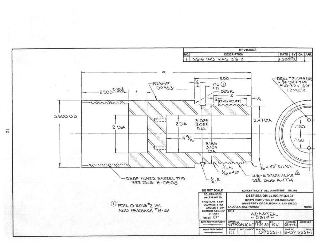
ADAPTER
SHOCK ABSORBER
BATTERY PACK
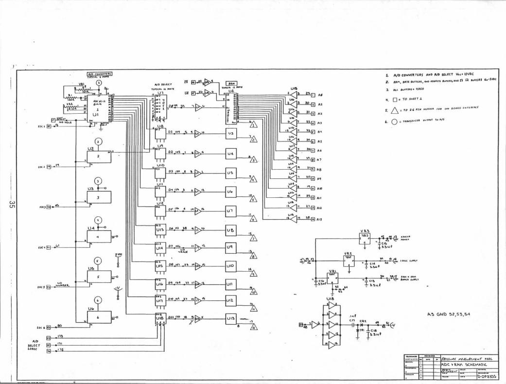
ELECTRONIC CIRCUIT BOARDS(6 channel capability)
PRESSURE CASE
PRESSURE TRANSDUCERS(4 channel capability)
BOTTOM CAP
CHECK VALVE
CORE BARREL
CORE LINER
CORE CATCHERS
i
vn

INDEX
I. DEPLOYMENT OF CORE BARREL INSTRUMENTATION,PRESSURE (CBIP)
II. INSTRUCTIONS FOR ASSEMBLY OF CBIP
III. PARTS LIST
IV. DRAWINGS
V. APPENDICES
A. PRESSURE MEASUREMENT TOOL RECORDERPACKAGE SPECIFICATIONS
B. TRANSDUCER SPECIFICATIONS
C. TRANSDUCER CALIBRATIONS
D. MEASURED DATA
IX
November 16, 1983
DEPLOYMENT OF CORE BARREL INSTRUMENTATION, PRESSURE (CBIP)
The CBIP has been deployed on two legs of the DSDP—Leg 94 and Leg 96. OnLeg 96, the calibration was improper, and no meaningful data was obtainedfrom the one run. On Leg 94, the CBIP was run four times, all with the ExtendedCore Barrel (XCB) system. The data from the first two runs, when plotted,showed lags in the response of the transducers caused by grease blockages inthe small pressure tubing leading from the ports to the transducers. This data,also, was considered not meaningful. The grease was cleared out of the tubingand provision was made to prevent any more grease from entering the tubing.
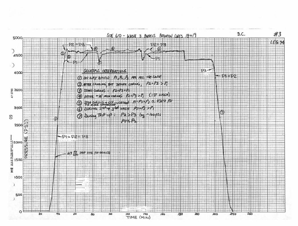
The last two runs of the CBIP, after the grease blockages were removed, yieldedvery good data. The plots of this data, labeled No. 3 and No. 4, are includedin this package. Plot No. 3 shows the increasing pressure as the instrumentdescended to the bottom of the drill string. After landing, but before coring,P2=P3 and both were greater than PI by about 270 psi. When coring started,the ball vent valve lifted against the 270 psi back pressure and P1=P2=P3 atabout 4600 psi. After coring was complete, the ball valve closed again andP2=P3>P1. When coring and circulation were stopped to make a connection, thepressures equalized at ambient pressure (about 4350 psi). A similar situationoccurred each time a connection was made. Finally, the plot shows decreasingpressure as the instrument was hauled back up to the surface.
Plot No. 4 shows events similar to those of Plot No. 3. However, one eventoccurred in run No. 4 that did not occur in run No. 3. That is the pressurespike just before the instrument was returned to the surface. It is believedthat this spike was due to the impact of the overshot landing on top of the corebarrel.
The data from these deployments of the CBIP have shown:
1) The drop rate of the core barrel is around 10 to 15 feet per second.
2) Because of the circulation a back pressure of 250 to 300 psi isimposed upon the ball vent before coring is started. This pressuremust be overcome, and the ball lifted, before water can vent offand core can be taken into the core barrel. Actually, at the startof coring, the water may be able to vent down around the outside ofthe core, but as the core becomes longer, this vent path becomesmore restrictive.
3) The pressures P2 and P3 are essentially equal throughout the entireoperation except for the trip back to the surface where P2 exceedsP3 by about 100 psi. The reason for this is not clear. The twopressure regions P2 and P3 are interconnected and should be equal.As the core barrel is being retrieved, the downward relative flowof water in the annulus may tend to produce a venturi effect in theregion of P3, but it seems that this would produce, if anything, alower pressure for P2. The dynamic pressure that would result fromthe velocity of retrieval is about 0.5 psi—nowhere near the 100 psidifference between P2 and P3.

The following recommendations are put forth for future work involving the CBIP
1) The instrument has only been run with the XCB system. The attemptto run it with the standard rotary coring system on Leg 94 did notproduce meaningful data. More attempts should be made with therotary system.
2) It would be useful to make a few runs of the CBIP without the ballin the venting system. It needs to be determined if the ball valveis really necessary, and if so, during what part of the operation itis needed. Perhaps some other arrangement could be set up wherebythe top of the core barrel is freely vented (with no back pressure)during coring and then is closed off during retrieval to preventwashing of the core.
/UJMfWDon Bellows
INSTRUCTIONS FOR ASSEMBLY OFCORE BARREL INSTRUMENTATION, PRESSURE (CBIP)
Refer to Assembly Drawing R-OP3330. The CBIP can be used with the StandardRotary Coring System or with the Extended Core Barrel (XCB).
1. Install O-Ring, Backup Ring and Rubber Shock Pad (OP3350) in BottomCap (OP3349). Install O-Ring and Backup Ring in Adapter (0P3331).
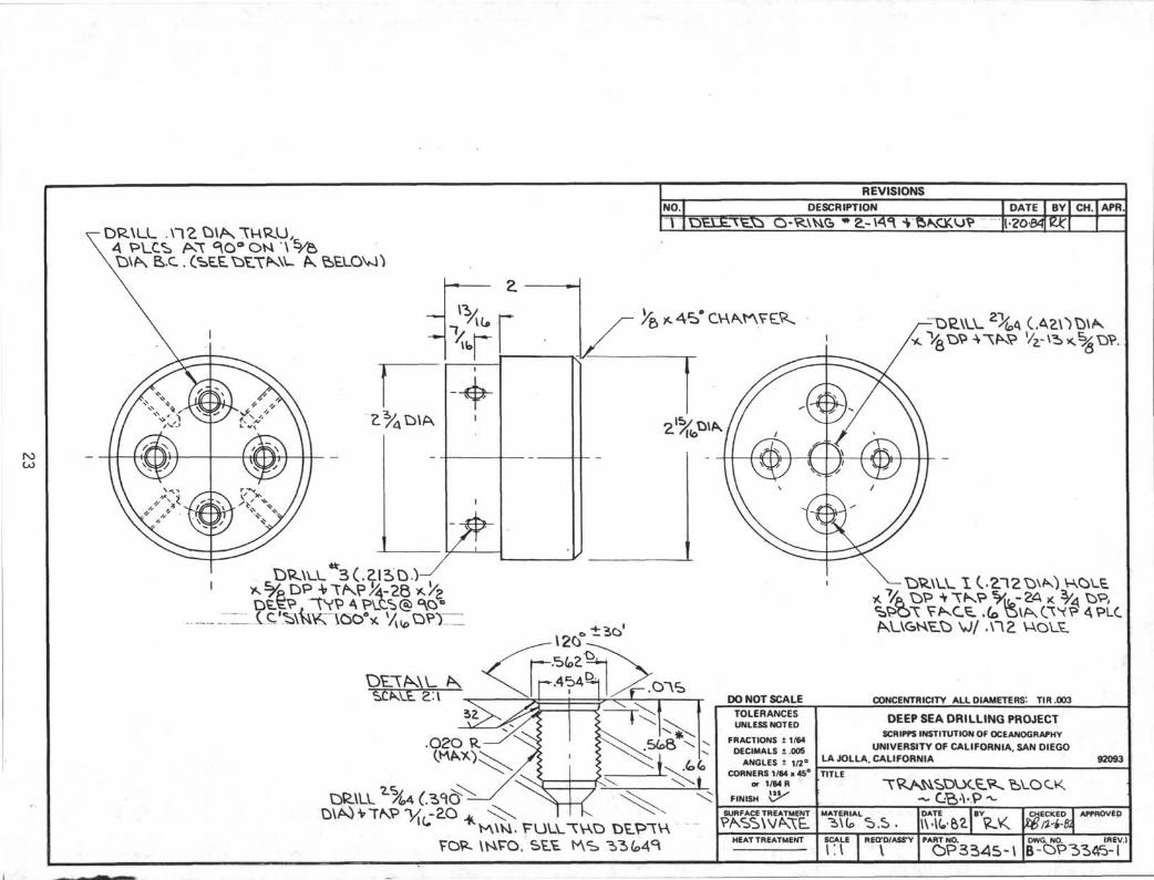
2. Install desired number of Pressure Transducers (1 to 4) on TransducerBlock (OP3345). Plug unused ports on Transducer Block with SwagelokPlugs. CBIP is designed to allow any one or all of three pressuremeasurements at top of core barrel, above ball valve, and in annulusbetween core barrel and drill pipe.
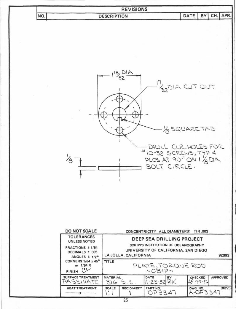
3. Assemble Bottom Cap to Torque Rod (OP3346) by means of Torque Rod Plate(OP3347) and Torque Rod Cap (0P3348).
4. Install 1/16 O.D. Pressure Tubing (OP3353) as required. Plug unusedports on top face of Bottom Cap with Swagelok Plugs. Plug unused pipethreaded ports with pipe plugs. From this point on, be careful thatPressure Tubing is not damaged by subsequent handling.
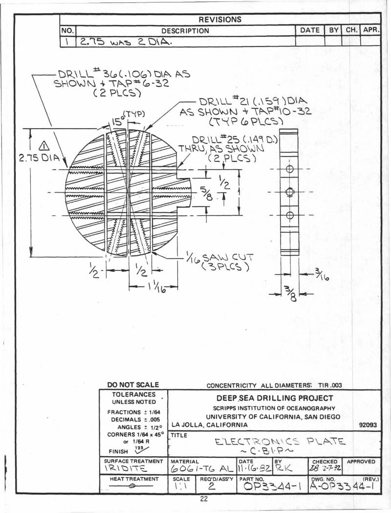
5. Attach half of Holding Tray (OP3342) to Transducer Block at one endand to Hang Plate (OP3338) at other end. Transducer Block goes at endnearest small holes (for mounting Electronics Package). InstallShock Rod (OP3333).
6. Install Electronics Pack and Battery Pack into Holding Tray and attachat bulkheads with screws as shown. Shock Indicator is optional—itmay or may not be installed. Make appropriate electrical connectionsbetween Battery Pack, Electronics Pack, and Pressure Transducers. Settimer (if tool is to be deployed soon) and install other half ofHolding Tray.
7. Slide Rebound Pad (OP3337) on to Shock Rod. Apply coating of siliconegrease to I.D. of Pressure Case (OP3340) where Bottom Cap O-ringswill contact. Also, apply Moly-D grease to threads on Bottom Capand Adapter.
8. Install inner assembly into Pressure Case by sliding in from endopposite previously installed Stop Plate (OP3336). Shock Rod willpass thru hole in center of Stop Plate and appear near end of PressureCase. Screw Bottom Cap into Pressure Case and tighten securely withstrap wrenches. If Shock Indicator has been installed, be carefulwhen handling and wrenching that large shocks are not applied which mightcause the Shock Indicator to trip prematurely.

Instructions for Assembly ofCore Barrel InstrumentationPressure (CBIP)
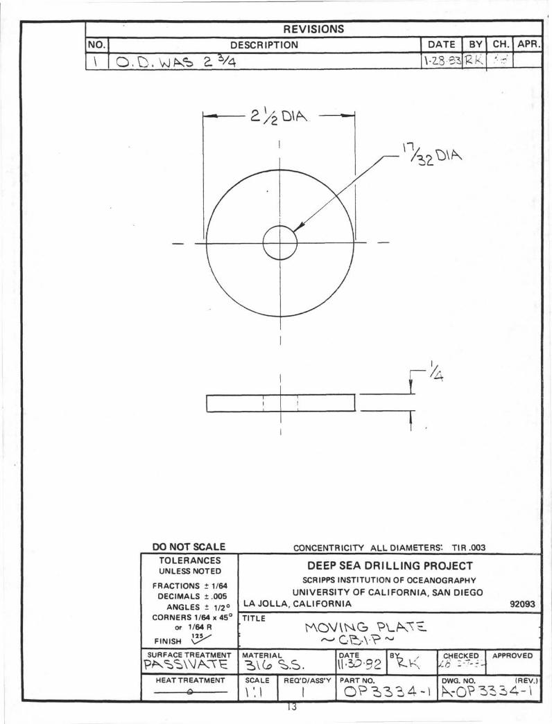
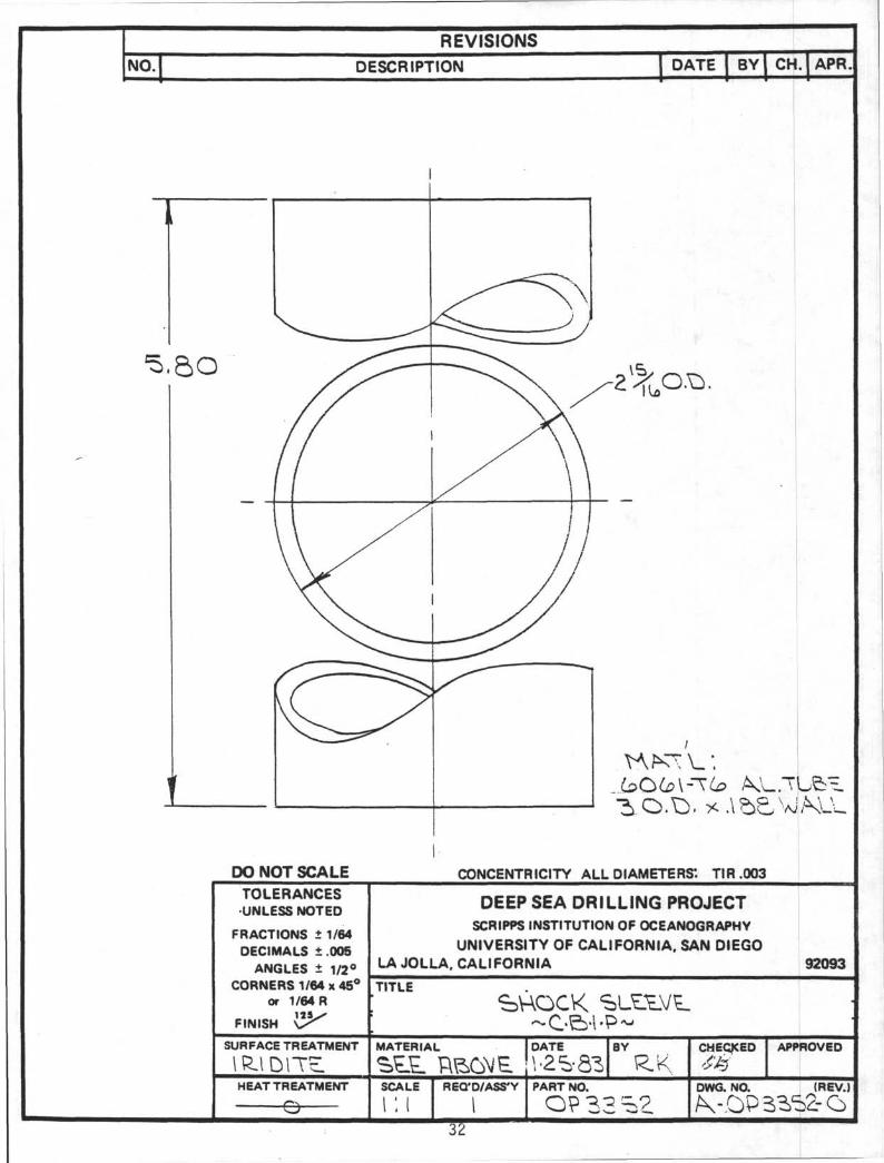
9. Pull end of Shock Rod until instrument package is fully extendedon Torque Rod. Install Shock Sleeve (OP-3352), Foam Shock Pad(OP-3335), and Moving Plate (OP-3334). Then install locknut onShock Rod.
10. Apply coating of silicone grease to I.D. of Pressure Case whereAdapter O-Rings will contact. Install Adapter and wrench downsecurely with strap wrenches. Shock Indicator is optional.
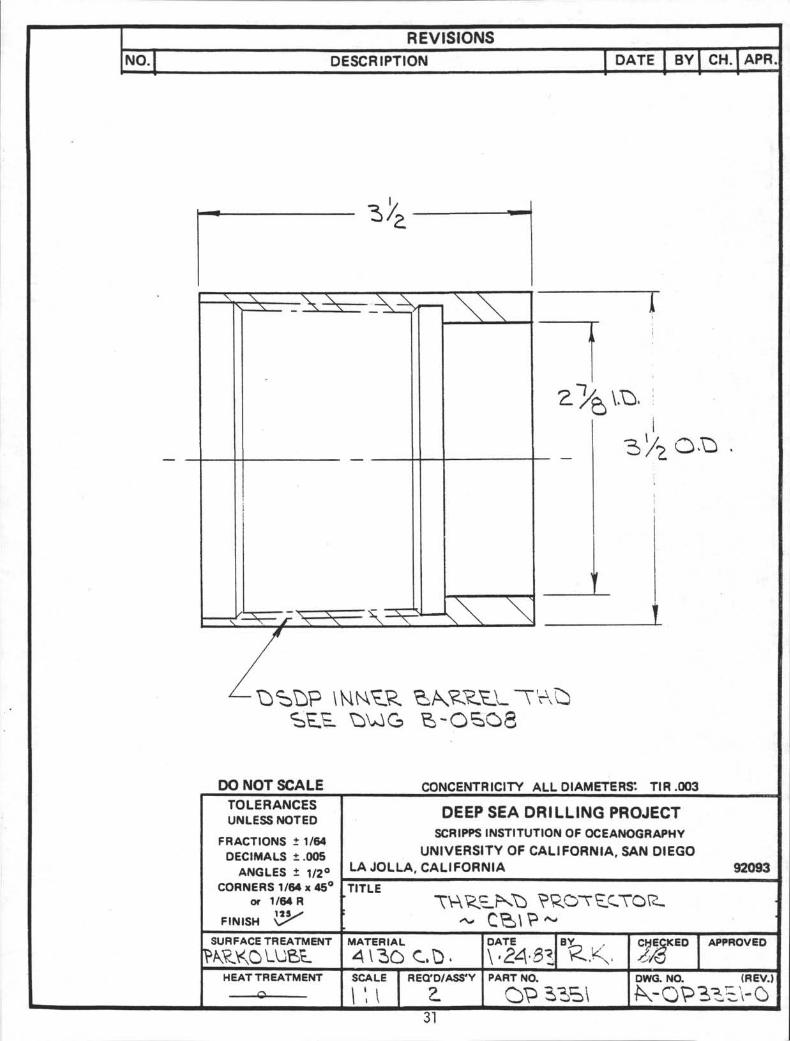
11. To use CBIP in Rotary Core Barrel, remove Thread Protector (OP-3351)Bottom end of CBIP attaches into top of core barrel; top endattaches into swivel. Length of CBIP, shoulder to shoulder, issix feet. To use in Extended Core Barrel (XCB) a double box sub(OP-3236) must be used at bottom of CBIP to mate with Vent Sub.A double pin sub (OP-4401) must be used at top of CBIP to matewith Quick Release Assembly.
There is no need for roughnecks to apply wrench to Pressure Case(OP-3340) and it should not be done. Wrench should be appliedonly to Adapter (OP-3331) or Bottom Cap (OP-3349) when connectingCBIP to core barrel.
The CBIP will be shipped completely assembled. To remove instrument packagefrom pressure housing, first take off Adapter. This will expose locknut onend of Shock Rod. Remove locknut. Entire instrument package may then beremoved by unscrewing Bottom Cap and pulling from bottom end.

PARTS LIST - CORE BARREL INSTRUMENTATION, PRESSURE (OP3330)
April 20, 1983DB
ITEM NO, DESCRIPTION PART NO. REQ'D SUPPLIER
123456789101112
14151617181920212223242526272829303132
AdapterMount, Shock Indicator (Optional)Shock RodMoving PlateShock Pad, FoamStop PlateRebound PadHang PlatePlate, BatteryPressure CasePlate, InsulatorHolding Tray
Electronics PlateTransducer BlockTorque RodPlate, Torque RodCap, Torque RodBottom CapShock Pad, RubberThread ProjectorShock Sleeve (optional)Pressure TubingP.C. Board AssemblyADC-RAM BoardLogic BoardTorque Rod AssemblyTie RodValve Seat RetainerPressure TransducerConnectorBattery, Gates 2 Volt, 2.5 AH D Cell
OP-3331OP-3332OP-3333OP-3334OP-3335OP-3336OP-3337OP-3338OP-3339OP-3340OP-3341OP-3342
OP-3344OP-3345OP-3346OP-3347OP-3348OP-3349OP-3350OP-3351OP-3352OP-3353OP-3354OP-3355OP-3356OP-3357OP-3358OP-3359CEC-1200
CEC 166267-00060810-0004
121111112141
2111111111-41111211-41-48
Tex Engrg (S.D.)Tex Engrg (S.D.)
Bell & Howell, CEC Div (L.A.)Bell & Howell, CEC Div (L.A.)Tauber Electronics (S.D.)

PARTS LIST - CORE BARREL INSTRUMENTATION, PRESSURE (OP3330)
April 20, 1983Page 2 DB
ITEM NO, DESCRIPTION PART NO, REQ'D SUPPLIER
cr>
33 Valve Seat & Ball34 Swagelok Connector35 Swagelok Plug36 Shock Indicator (optional)37 Retaining Ring38 Pipe Plug39 O-Ring, Parker (spare for Item 30)40 O-Ring, Parker (space for Item 34)
42 O-Ring, Parker
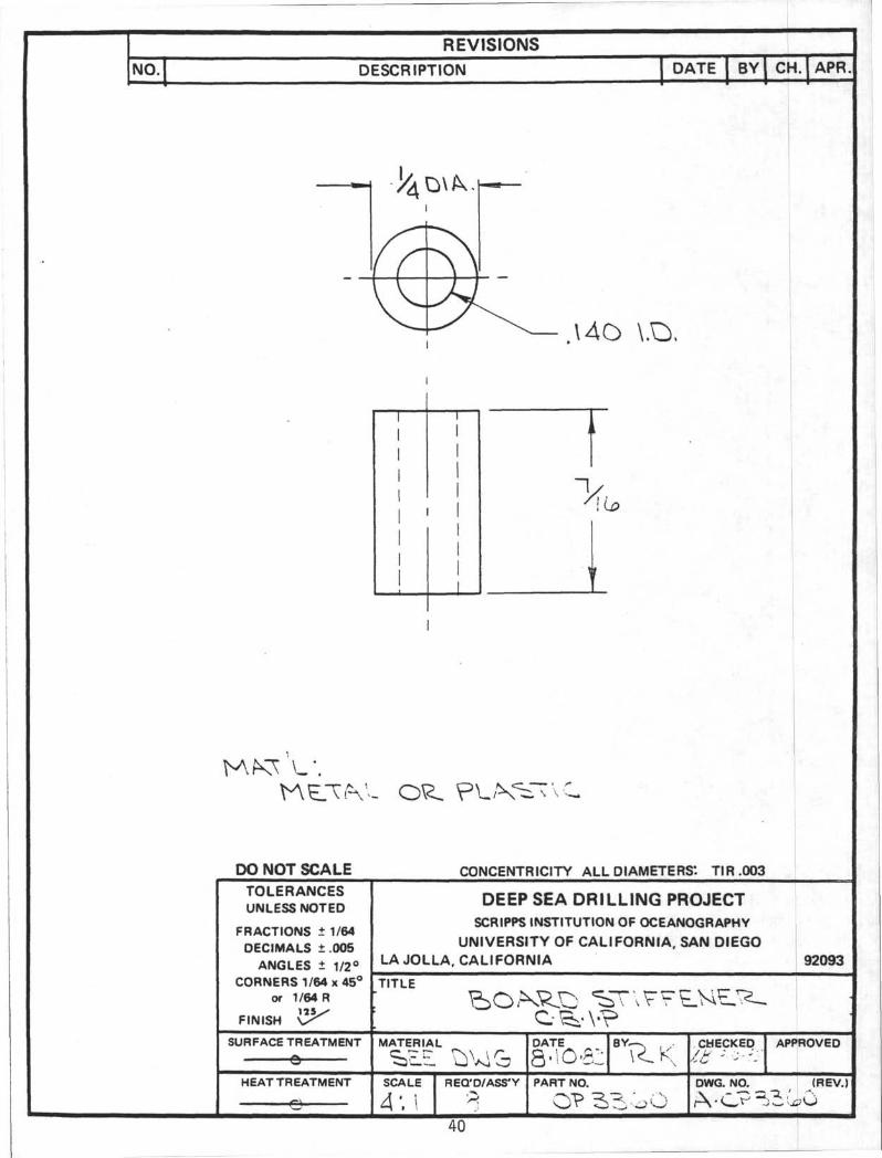
44 Backup Ring, Parker45 SS Flat HD Screw, 100°, %-28 x h46 SS Soc HD Cap Screw, 10-32 x h (optional, shock indicator)47 SS Flat HD Screw, 100°, 10-32 x 5/8.48 SS Soc HD Cap Screw, 6-32 x 249 SS RD HD Screw, 6-32 x h (optional-shock indicator)50 SS Lock Nut, 6-32 (optional-shock indicator)51 SS Hex Locknut, J -1352 SS Hex Nut, -1353 SS Cotter Pin, 1/8 x 154 Loctite Threadlocker55 Loctite Threadlocker56 Loctite Threadlocker57 Loctite Superbonder 49558 Cyanoacrylate Prep59 Silicone Grease60 Molylube61 Teflon Tape62 Connector, Trailer Lite, 2-Pole63 SS Hex Nut, 1/4-2064 Board Stiffener
2E3SS-100-1-ORSS-100-PSR-355N5OOO-3OO1/8 HHP-SSMS28775-0122-011N674-70
2-151N674-70
8-151
222271277
7520A1175O2A111286K111279K24591K11
OP-3360
12-80-60-220-81-4
2
216412466111
A/RA/RA/RA/RA/RA/RA/RA/R128
Harbison-Fischer (Tex)San Diego Valve (S.D.)San Diego Valve (S.D.)Inertia Switch (N.Y.)King Bearing (S.D.)Aero Space Supply (S.D.)Aero Space Supply (S.D.)Aero Space Supply (S.D.)
Aero Space Supply (S.D.)
Aero Space Supply (S.D.)Pell Mell Supply (S.D.)Pell Mell Supply (S.D.)Pell Mell Supply (S.D.)Pell Mell Supply (S.D.)Pell Mell Supply (S.D.)Pell Mell Supply (S.D.)Pell Mell Supply (S.D.)Pell Mell Supply (S.D.)Pell Mell Supply (S.D.)Yale Enterprises (S.D.)Yale Enterprises (S.D.)Yale Enterprises (S.D.)McMaster-Carr (L.A.)McMaster-Carr (L.A.)McMaster-Carr (L.A.)McMaster-Carr (L.A.)McMaster-Carr (L.A.)Kragen (S.D.)Aero Space Supply (S.D.)

PARTS LIST - CORE BARREL INSTRUMENTATION, PRESSURE (OP333Q)ELECTRONICS
April 20, 1983Page 3 DB
ITEM NO, DESCRIPTION REQ D SUPPLIER
123456789101112131415161718192021222324252627282930313233
RAMA-DICICICICICICICICICICICICICICVRVRVRDiodeCrystalDip SwitchPot (Bournes)CAPCAP (Sprague)CAP, Trim (Johanson)Header (Alpha)Push ButtonCAPCAPCAPCAPSocket
MB8167-70CADC HC-12BMMCD 4051 BECD 4050 BECD 4518 BECD 4520 BECD 4059 AECD 4017 BECD 4045 BECD 4069 BECD 4053 BECD 4070 BECD 4081 BECD 4022 BECD 4078 BECD 4013 BEUA 7805 CKCUA 7810 CKCUA 7812 CKC1N91476F829DYS813F3419CK05BX10417F20539614FCC 151-2613F364714F127014F127414F128113F505438F1560
12612733141212223411110111213611111111
R.V. WEatherford (S.D.)Datel-Intersil (Santa Ana)Newark Electronics (S.D.)Newark Electronics (S.D.)Newark Electronics (S.D.)Newark Electronics (S.D.)Newark Electronics (S.D.)Newark Electronics (S.D.)Newark Electronics (S.D.)Newark Electronics (S.D.)Newark Electronics (S.D.)Newark Electronics (S.D.)Newark Electronics (S.D.)Newark Electronics (S.D.)Newark Electronics (S.D.)Newark Electronics (S.D.)Newark Electronics (S.D.)Newark Electronics (S.D.)Newark Electronics (S.D.)Newark Electronics (S.D.)Newark Electronics (S.D.)Newark Electronics (S.D.)Newark Electronics (S.D.)Newark Electronics (S.D.)Newark Electronics (S.D.)Newark Electronics (S.D.)Newark Electronics (S.D.)Newark Electronics (S.D.)Newark Electronics (S.D.)Newark Electronics (S.D.)Newark Electronics (S.D.)Newark Electronics (S.D.)Newark Electronics (S.D.)

REVISIONS
NO DESCRIPTION DATE BV
t
CH APR
REVISIONSNO. DESCRIPTION DATE BY CH. APR.
o
DO NOT SCALE CONCENTRICITY ALL DIAMETERS'. TIR .003
TOLERANCESUNLESS NOTED
FRACTIONS t 1/64DECIMALS 1.005
ANGLES t 1/2°CORNERS 1/64 • 45°
or 1/64 R
FINISH V ^
SURFACE TREATMENT
HEAT TREATMENT
DEEP SEA DRILLING PROJECTSCRIPPS INSTITUTION OF OCEANOGRAPHY
UNIVERSITY OF CALIFORNIA. SAN DIEGOLA JOLLA. CALIFORNIA 92093TITLE
- c e> i p
SCALE REQD/ASS•Y
\\•24&2. tßn•T-li•

REVISIONS
NO. DESCRIPTION DATE BY CH. APR.
\2O° OU \ .25
\
DO NOT SCALE CONCENTRICITY ALL DIAMETERS*. TIR.003TOLERANCESUNLESS NOTED
FRACTIONS ± 1/64DECIMALS ±.005
ANGLES ± 1/2°CORNERS 1/64x45°
or 1/64 R125
FINISH
SURFACE TREATMENT
P/WHTHEAT TREATMENT
0
DEEP SEA DRILLING PROJECTSCRIPPS INSTITUTION OF OCEANOGRAPHY
UNIVERSITY OF CALIFORNIA, SAN DIEGOLA JOLLA, CALIFORNIA 92093
TITLE
MATERIAL
SCALE REQ'D/ASS'Y
11
DATE
I2 l•32BY
PART NO.
CHECKED APPROVED
DWG. NO. (REV.

REVISIONS
NO. DESCRIPTION DATE BY CH. APR
DO NOT SCALE CONCENTRICITY ALL DIAMETERS*. TIR.003
TOLERANCESUNLESS NOTED
FRACTIONS ± 1/64DECIMALS ± .005
ANGLES ± 1/2°CORNERS 1/64 x 45°
or 1/64 R
FINISH
DEEP SEA DRILLING PROJECTSCRIPPS INSTITUTION OF OCEANOGRAPHY
UNIVERSITY OF CALIFORNIA, SAN DIEGOLA JOLLA, CALIFORNIA 92093TITLE
SURFACE TREATMENT MATERIAL DATE BY APPROVED
HEAT TREATMENT SCALE REQ'D/ASS'Y PART NO.
P 3.DWG. NO. (REV.)
12
NO.
\ O.
REVISIONSDESCRIPTION DATE
vz<sezBY
UKCH. APR.
DO NOT SCALE CONCENTRICITY ALL DIAMETERS*. TIR.003TOLERANCESUNLESS NOTED
FRACTIONS ± 1/64DECIMALS ±.005
ANGLES ± 1/2°CORNERS 1/64x45°
or 1/64 R
FINISH V ^
SURFACE TREATMENT
HEAT TREATMENT
DEEP SEA DRILLING PROJECTSCRIPPS INSTITUTION OF OCEANOGRAPHY
UNIVERSITY OF CALIFORNIA, SAN DIEGOLA JOLLA, CALIFORNIA 92093
TITLE
MATERIAL
SCALE REQ D/ASS Y
TT
DATE
PART NO.
CHECKEDx.c 1-7-é•
APPROVED
DWG. NO. (REV.)

REVISIONS
NO. DESCRIPTION DATE BY CH. APR.
α
DO NOT SCALE CONCENTRICITY ALL DIAMETERS". TIR.003
TOLERANCESUNLESS NOTED
FRACTIONS ± 1/64DECIMALS ± 0 0 5
ANGLES ± 1/2°CORNERS 1/64x45°
or 1/64 R115
FINISH
SURFACE TREATMENT
HEAT TREATMENT
e
DEEP SEA DRILLING PROJECTSCRIPPS INSTITUTION OF OCEANOGRAPHY
UNIVERSITY OF CALIFORNIA, SAN DIEGO
LA JOLLA, CALIFORNIA 92093
TITLE
~~ C ‰VPMATERIAL
SCALE
I". IREQ'D/ASS'Y
14
DATE
PART NO
OP
..CHECKED APPROVED
DWG. NO. (REV.)

REVISIONS
NO. DESCRIPTION DATE BY CH. APR.
1 1
i~/k
DO NOT SCALE CONCENTRICITY ALL DIAMETERS*. TIR.003
TOLERANCESUNLESS NOTED
FRACTIONS ± 1/64DECIMALS ±.005
ANGLES ± 1/2°CORNERS 1/64x45°
or 1/64 R
FINISH
DEEP SEA DRILLING PROJECTSCRIPPS INSTITUTION OF OCEANOGRAPHY
UNIVERSITY OF CALIFORNIA, SAN DIEGO
LA JOLLA, CALIFORNIA 92093
TITLE
SURFACE TREATMENT MATERIAL
S.S.DATE B Y , CHECKED APPROVED
HEAT TREATMENT
θSCALE REQ D/ASS Y PART NO. DWG. NO. (REV.)

REVISIONS
NO. DESCRIPTION DATE BY CH. APR.
1
1
111
i
11
11
1
\
DO NOT SCALE CONCENTRICITY ALL DIAMETERS'. TIR.003
TOLERANCESUNLESS NOTED
FRACTIONS ± 1/64DECIMALS ±.005
ANGLES ± 1/2°CORNERS 1/64x45°
or 1/64 R
FINISH
DEEP SEA DRILLING PROJECTSCRIPPS INSTITUTION OF OCEANOGRAPHY
UNIVERSITY OF CALIFORNIA, SAN DIEGOLA JOLLA, CALIFORNIA 92093
TITLE
SURFACE TREATMENT
θMATERIAL DATE BY CHECKED APPROVED
HEAT TREATMENT SCALE REQ'D/ASS'Y
16
PART NO.
OPDWG. NO. (REV.)

REVISIONS
NO. DESCRIPTION DATE BY CH. APR
DO NOT SCALE CONCENTRICITY ALL DIAMETERS". TIR.003
TOLERANCESUNLESS NOTED
FRACTIONS ± 1/64DECIMALS ±.005
ANGLES ± 1/2°CORNERS 1/64x45°
or 1/64 R
FINISH
SURFACE TREATMENT
HEATTREATMENT
DEEP SEA DRILLING PROJECTSCRIPPS INSTITUTION OF OCEANOGRAPHY
UNIVERSITY OF CALIFORNIA, SAN DIEGO
LA JOLLA, CALIFORNIA 92093
TITLE
C ‰v~MATERIAL
Aλ-USCALE
\:
REQ'D/ASS'Y
17
DATE
\\ Z? 33BY
PART NO.
OP 5
CHECKED APPROVED
DWG. NO. (REV.)

REVISIONS
NO. DESCRIPTION DATE BY CH. APR
%
2*4—
ZPLC ACTOH \ 7^ D I N
DO NOT SCALE CONCENTRICITY ALL DIAMETERS'. TIR.003TOLERANCESUNLESS NOTED
FRACTIONS ± 1/64DECIMALS ±.005
ANGLES ± 1/2°CORNERS 1/64x45°
or 1/64 R
FINISH
SURFACE TREATMENT
\CL\OVTE.HEAT TREATMENT
e
DEEP SEA DRILLING PROJECTSCRIPPS INSTITUTION OF OCEANOGRAPHY
UNIVERSITY OF CALIFORNIA, SAN DIEGOLA JOLLA; CALIFORNIA 92093
TITLE
MATERIAL
SCALE REQ'D/ASS'Y
18
OATE
\\ 23BY
PART NO.
OP
CHECKED
SC
>SAPPROVED
DWG. NO. (REV.)!

CONCENTRICITY ALL DIAMETERS*. TIR.OO3
TOLERANCESUNLESS NOTED DEEP SEA DRILLING PROJECT
SCRIPPS INSTITUTION OF OCEANOGRAPHYUNIVERSITY OF CALIFORNIA. SAN DIEGO
LA JOLLA. CALIFORNIA
FRACTIONS i 1/64DECIMALS ±005
ANGLES ± 1/2°CORNERS 1/64 11 45
or 1/64 R
SURFACE TREATMENT CHECKED APPROVED

REVISIONS
NO. DESCRIPTION DATE BY CH. APR
DO NOT SCALE CONCENTRICITY ALL DIAMETERS*. TIR.003
TOLERANCESUNLESS NOTED
FRACTIONS ±1/64DECIMALS ± .008
ANGLES ± 1/2°CORNERS 1/84 » 49°
or 1/64 R
FINISH
SURFACE TREATMENT
θ
HEAT TREATMENT
DEEP SEA DRILLING PROJECT
SCRIPTS INSTITUTION OF OCEANOGRAPHYUNIVERSITY OF CALIFORNIA, SAN DIEGO
LA JOLLA, CALIFORNIA 92093
TITLIPLKVH. ,
MATERIAL
PVCSCALE
\\\
RECTD/ASS Y
420
DATE
PART MO.
CHECKED APPROVED
DWG. NO. (REV.)

ro
REVISIONS
NO.
\
Z
DESCRIPTION
K U b L t > N V & HOLES.
DATE
5 lθ 8?
BY CH. APR.
TOLERANCESUNLESS NOTED
FRACTIONS ± 1/64DECIMALS ±005
ANGLES 1 1/2°CORNERS 1/64 x 45°
or 1/64 R
FINISH
SURFACE TREATMENT
HEAT TREATMENT
ö
DEEP SEA DRILLING PROJECTSCRIPPS INSTITUTION OF OCEANOGRAPHY
UNIVERSITY OF CALIFORNIA, SAN DIEGOLA JOLLA. CALIFORNIA 92093
TITLE
c ‰v?
SCALE REQ'D/ASS•Y
\
U 23 8Z
- 2.
n•è•n
REVISIONS
NO. DESCRIPTION DATE BY CH. APR.
C 2-32
DO NOT SCALE CONCENTRICITY ALL DIAMETERS". TIR.003TOLERANCESUNLESS NOTED
FRACTIONS ± 1/64DECIMALS ±.005
ANGLES ± 1/2°CORNERS 1/64x45°
or 1/64 R
FINISH O
SURFACE TREATMENT
HEAT TREATMENT
DEEP.SEA DRILLING PROJECTSCRIPPS INSTITUTION OF OCEANOGRAPHY
UNIVERSITY OF CALIFORNIA, SAN DIEGOLA JOLLA, CALIFORNIA 92093
TITLE
MATERIAL
A LSCALE REQ'D/ASS'Y
22
DATE BY
PART NO.
CHECKED
IS 7-7-91APPROVED
WG. NO. (REV.
CO
E>.C . C^EEtiETNW-
DP -VTKP^-28 At V P A
CONCENTRICITY ALL DIAMETERS'- TIR.003
DEEP SEA DRILLING PROJECTSCRIPPS INSTITUTION OF OCEANOGRAPHY
UNIVERSITY OF CALIFORNIA. SAN DIEGOLA JOLLA. CALIFORNIA 92093
FRACTIONS t 1/64DECIMALS ± 005
ANGLES ± 1/2CORNERS 1/64 x 45
or 1/64 R
FUU.THO DEPTH. SEE OP3545-1

DO NOT SCALE CONCENTRICITY ALL DIAMETERS*. TIR.003
TOLERANCESUNLESS NOTED
FRACTIONS ± 1/64DECIMALS ±.005
ANGLES ± 1/2°CORNERS 1/64 x 45°
or 1/64 R
FINISH \S
SURFACE TREATMENT
HEAT TREATMENT
θ
DEEP SEA DRILLING PROJECTSCRIPPS INSTITUTION OF OCEANOGRAPHY
UNIVERSITY OF CALIFORNIA, SAN DIEGO
LA JOLLA, CALIFORNIA 92093
TITLE
MATERIAL
SCALE
V. IREQ'D/ASS'Y
24
DATE
\VZ5 52BY^
PART NO.
CHECKED APPROVED
DWG. NO. (REV.
REVISIONS
NO. DESCRIPTION DATE BY CH. APR
CUT O J
DO NOT SCALE CONCENTRICITY ALL DIAMETERS*. TIR.003
TOLERANCESUNLESS NOTED
FRACTIONS ± 1/64DECIMALS ± 0 0 5
ANGLES ± 1/2°CORNERS 1/64 x 45°
or 1/64 R
FINISH
DEEP SEA DRILLING PROJECTSCRIPPS INSTITUTION OF OCEANOGRAPHY
UNIVERSITY OF CALIFORNIA, SAN DIEGOLA JOLLA, CALIFORNIA
TITLE
92093
SURFACE TREATMENT MATERIAL DATE
w-iz azBY CHECKED APPROVED
HEAT TREATMENT
θ
SCALE
\\\
REQ'D/ASS'Y
25
PART NO.
OPDWG. NO. (REV.)

REVISIONS
NO. DESCRIPTION DATE BY CH. APR,
DO NOT SCALE CONCENTRICITY ALL DIAMETERS*. TIR .003
TOLERANCESUNLESS NOTED
FRACTIONS ± 1/64DECIMALS ±.005
ANGLES ± 1/2°CORNERS 1/64x45°
or 1/64 R
FINISH
SURFACE TREATMENT
HEAT TREATMENT&
DEEP SEA DRILLING PROJECTSCRIPPS INSTITUTION OF OCEANOGRAPHY
UNIVERSITY OF CALIFORNIA, SAN DIEGOLA JOLLA, CALIFORNIA 92093
TITLE
MATERIAL
SCALE REQ'D/ASS'Y
26
DATE
U•lZ SS iPART NO.
OP
.CHECKED,/J /Z-/-w• >
APPROVED
DWG. NO. (REV.

REVISIONS
DESCRIPTION
=> p\_ç t
DATE BY CH. APR
DfcALL .\O-32 K.
PLCS K^ '=tO* OH
DR.W-L \ \}\K TVAR.U
4S*
©
TOLERANCESUNLESS NOTED
FRACTIONS 1 1/64DECIMALS 1.005
ANGLES ± 1/2°CORNERS 1/M > 45°
at I/MR
FINISH Z×SURFACE TREATMENT
HEAT TREATMENT
DEEP SEA DRILLING PROJECTSCRIPPS INSTITUTION OF OCEANOGRAPHY
UNIVERSITY OF CALIFORNIA, SAN DIEGOLA JOLLA, CALIFORNIA
TITLE
*TNO.
OP
AWN BY DATE CHECKED APPROVED
RCV.
^

REVISIONSNO. DESCRIPTION ] DATE f BY CH. APR.
+ KXZ-H> ?\TCH-/
J
I CVLR
HIMOR t
f PITCH~TUO
j ^ . u\K
'ALL DiAMETIB .00:
TOLERArv CESUNLESS NOTED
FRACTIONS i 1/64 }DECIMALS ÷.OOf>
tlPSuA DRfLLSNG PROJECT?$ IMCTtTL•üON OP OCEANOGRAPHY
RSJTY Or CALIFORNIA, SAM üicGG; A .>CU.A,
CORNERS 1/64 x 4F-° j TiTl.~or t/64 R C"? S
92093 j
1
• 28

rNO.
REVISIONS
DESCRIPTION
II
N O Λ L
\\ \ \
r \ \ H
t*s • Λ
« I
l ço.
/ s2
j TOLERANCfcS\ UNLESS NO f ED
5 Q
•'t
ü>
. U
VWKO^V> 3.02.5!
Cπ04
SONS i 1/64DECIMALS t .CCS
ANGLES r. I/?." [ L A J Q J L A
* CORN^^S !/64 x 4 i" rTπTi'or »/64R f S
i.
DEEP SEA DRSLLiNG PROJECSCR1PPS INSTITUTION OF OCcANOGft/^
FINISH \ ^
SURFACE TRSAIMKN Π MATERIAL
r
j"29 A-

REVISIONS
NO. DESCRIPTION DATE BY CH. APR.
O
DO NOT SCALE CONCENTRICITY ALL DIAMETERS*. TIR.003
TOLERANCESUNLESS NOTED
FRACTIONS ± 1/64DECIMALS ±005
ANGLES ± 1/2°CORNERS 1/64x45°
or 1/64 R
FINISH
SURFACE TREATMENTa
HEAT TREATMENT
DEEP SEA DRILLING PROJECTSCRIPPS INSTITUTION OF OCEANOGRAPHY
UNIVERSITY OF CALIFORNIA, SAN DIEGOLA JOLLA, CALIFORNIA 92093
TITLESHOCK
.MATERIAL
SCALE REQ'D/ASS'Y
30
DATE
PART NO.
OF 335O
CHECKED APPROVED
DWG. NO. (REV.
0
REVISIONSNO. DESCRIPTION DATE BY CH. APR.
DO NOT SCALE CONCENTRICITY ALL DIAMETERS*. TIR.003TOLERANCESUNLESS NOTED
FRACTIONS ± 1/64DECIMALS ±005
ANGLES ± 1/2°CORNERS 1/64 x 45°
or 1/64 R
FINISH
DEEP SEA DRILLING PROJECTSCRIPPS INSTITUTION OF OCEANOGRAPHY
UNIVERSITY OF CALIFORNIA, SAN DIEGOLA JOLLA, CALIFORNIA
TITLE
92093
SURFACE TREATMENT MATERIAL
4\3O CO.DATE CHECKED
4/3APPROVED
HEAT TREATMENT SCALE
\WREQ D/ASS Y
31
PART NO.
OPDWG. NO. (REV.)
REVISIONS
NO. DESCRIPTION DATE BY I CH.ICH.1APR.
DO NOT SCALE CONCENTRICITY ALL DIAMETERS*. TIR.003TOLERANCESUNLESS NOTED
FRACTIONS ± 1/64DECIMALS ±005
ANGLES ± 1/2°CORNERS 1/64 x 45°
or 1/64 R
FINISH
SURFACE TREATMENT
HEAT TREATMENT
e—
DEEP SEA DRILLING PROJECTSCRIPPS INSTITUTION OF OCEANOGRAPHY
UNIVERSITY OF CALIFORNIA. SAN DIEGOLA JOLLA. CALIFORNIA 92093
TITLESHOCK
MATERIAL
SCALE REQ'0/ASS'Y
32
DATE BY
R.KPART NO.
CHECKED APPROVED
DWG. NO. (REV.) I

REVISIONSNO. DESCRIPTION
2.V4DATE
2JÙ•84\
BY CH. APR.
CO
////
4h
FULLV
DO NOT SCALE CONCENTRICITY ALL DIAMETERS: TIR.003
X .
TOLERANCESUNLESS NOTED
FRACTIONS i 1/64
DECIMALS 1.005
ANGLES ± 1/2°
CORNERS 1/64 x 45°or 1/64 R
FINISH
SURFACE TREATMENT
HEAT TREATMENT
DEEP SEA DRILLING PROJECTSCRIPPS INSTITUTION OF OCEANOGRAPHY
UNIVERSITY OF CALIFORNIA. SAN DIEGOLA JOLLA. CALIFORNIA
TITLE
SCALE
HO
CKED I APPROVED
DWG. NO.
B-O

CO
NO.
AND
TO Bε ftRRANöεD NOT TO
2" D X A A i r r r f l U/HETW
GROUND TO B£TO BOTH SCREW HOLES ON
or «*-t-
T1*
1.BOTHENPS
r
&
REVISIONS
DESCRIPTION
urn
o# é SCREW
HOLES
i sεr ro
6" OF T0TβL LBM6TH
o
TO Bε
5IN6LC ISO"
OF BOARDS NOT FIXED AT 3
26
W/O LflTCH HOOKS
PLftcεN\£NT OF COMPONENTS
NOT CRITICAL EXCEPT OS NOTED
DO NOT SCALE
DATE BY I CH. APR
CONCENTRICITY ALL DIAMETERS'. TIR .003
TOLERANCESUNLESS NOTED
FRACTIONS ft 1/64DECIMALS ± .005
ANGLES i 1/2°CORNERS 1/64 x 45°
or 1/64 R
FINISH
SURFACE TREATMENT
HEAT TREATMENT
DEEP SEA DRILLING PROJECT
SCRIPPS INSTITUTION OF OCEANOGRAPHY
UNIVERSITY OF CALIFORNIA. SAN DIEGOLA JOLLA, CALIFORNIA 92093
TITLE
RC.bOMΦ
SCALE REQ D/ASS•Y
CHECKED APPROVEO
(REV.
JüT•ü l - i ..„ ~ ft>iis»«ε /"taioefs t~r TOOL


REVISIONSNO. DESCRIPTION DATE BY CH. APR
DO NOT SCALE CONCENTRICITY ALL DIAMETERS*. TIR.003
TOLERANCESUNLESS NOTED
FRACTIONS ± 1/64DECIMALS ±.005
ANGLES ± 1/2°CORNERS 1/64x45°
or 1/64 R
FINISH
SURFACE TREATMENT
HEAT TREATMENT
DEEP SEA DRILLING PROJECTSCRIPPS INSTITUTION OF OCEANOGRAPHY
UNIVERSITY OF CALIFORNIA, SAN DIEGOLA JOLLA, CALIFORNIA 92093
TITLE
MATERIAL
SCALE REQ'D/ASS Y
37
DATE BY
PART NO.
CHECKED APPROVED
DWG. NO. (REV.

REVISIONS
NO. DESCRIPTION DATE | BY | CH. | APR
DO NOT SCALE CONCENTRICITY ALL DIAMETERS". TIR.003
TOLERANCESUNLESS NOTED
FRACTIONS ± 1/64DECIMALS ±.005
ANGLES ± 1/2°CORNERS 1/64x45°
or 1/64 R
FINISH
SURFACE TREATMENT
HEAT TREATMENTθ
DEEP SEA DRILLING PROJECTSCRIPPS INSTITUTION OF OCEANOGRAPHY
UNIVERSITY OF CALIFORNIA, SAN DIEGO
LA JOLLA, CALIFORNIA 92093
TITLE
MATERIAL
SCALE REQ'D/ASS'Y
38
DATE
Z-VBY
PART NO.
CHECKED APPROVED
DWG. NO. (REV.)

REVISIONSNO. DESCRIPTION DATE BY CH. APR.
DO NOT SCALE CONCENTRICITY ALL DIAMETERS*. TIR.003TOLERANCESUNLESS NOTED
FRACTIONS ± 1/64DECIMALS ±005
ANGLES ± 1/2°CORNERS 1/64x45°
or 1/64 R
FINISH
DEEP SEA DRILLING PROJECTSCRIPPS INSTITUTION OF OCEANOGRAPHY
UNIVERSITY OF CALIFORNIA, SAN DIEGOLA JOLLA, CALIFORNIA
TITLE
C ‰vP
92093
SURFACE TREATMENT MATERIAL DATE BY CHECKED APPROVED
HEAT TREATMENT
&
SCALE REQ'D/ASS'Y
39
PART NO. DWG. NO, (REV.)
REVISIONS
NO. DESCRIPTION DATE BY CH. APR
\4O
DO NOT SCALE CONCENTRICITY ALL DIAMETERS*. TIR.003
TOLERANCESUNLESS NOTED
FRACTIONS ± 1/64DECIMALS ±005
ANGLES ± 1 / 2 °CORNERS 1/64x45°
or 1/64 R
FINISH
SURFACE TREATMENTQ
HEAT TREATMENT
DEEP SEA DRILLING PROJECTSCRIPPS INSTITUTION OF OCEANOGRAPHY
UNIVERSITY OF CALIFORNIA, SAN DIEGOLA JOLLA, CALIFORNIA 92093
TITLE
MATERIAL
ji oSCALE
4'. IREQ D/ASS Y
DATE
a io•s:BY,
PART NO.
CHECKED APPROVED
DWG. NO. (REV.)

APPENDIX A
Pressure Measurement ToolRecorder Package Specifications
42

Pressure Measurement ToolRecorder Package
Spec i f i cat i ons
Power Requirements 16 VDC, 5 Watts
Memory 16384 data points total.The number of samples isdetermined by the totalnumber of inputs.<4 inputs= 4896 samples;
Sample Rates 1 sample every 5.12, 2.56*1.28, .64, or .32 sec.jumper selectable
Data Output 12 bit binary (si gn e dmagnitude) TTL comp.
Env i ronrnen tal 0 to 85 C, 25g shockj i0,000 pzi
Transducers Bell and Howe 11 CEC-12G0Q to 5 VDC output, 18,8031 bs max wor• king p r ?ssur e .12 to 48 K>DC unregulatedexcitation, common to toolside of input plug.
Number of Inputs 2 to Each transducerrequires 1 wire, ft "1 ^ i gn " :1 ow a •-• d exciter g r o 'J n d ;: I n scommon to tool side of plug
43

Pressure Measurement ToolDeck Interface
Spec i fi cat i ons
Power requirements
Inputs-from host computer
-from tool
Outputsto host computer
to tool (read data only)
to tool (calibrate)
v i sual
44
128 VAC
.5 uSec negative pulse toto initiate each byte ofdata transfer. Also dataaccepted. This is a pos.transition on completion ofeach byte transfeRred.
12 bi t byte of data,CMOS compatible.
TTL or
12 bit signed magnitudebyte. Also Data Available(logic high when data islatched into interface).
Chip Enable -. This is a .5uSec negative pulse fromthe host computer.Address Step. This is thepositive transition of dotaccepted.
Chip Enable -.pulse.Ulr i te Enabl e -Star t Conver t.opposi te Wr i teAddress Step.with channel select.
3 uSec neg
20 Hz20 Hz signalenable.
12 bit status(on +)
indicators.

Pressure Measurement Tool
The recorder package is constructed of low power consumption
C-MOS integrated circuits and a crystal controlled oscillator, -for
low battery drain and stability over long periods of time. The
battery pack consists o-f eight 2 UDC lead acid cells hooked in
series -for a total of 16 {JDC. Total depl oyrrien t times in excess of
16 hours should be easily attained, with data retention times
running into days. Sample rates are jumper selectable at 5.12,
2.56, and .64 sec. per sample. These rates can.also be doubled by
moving a jumper to provide rates o f 2.56, 1.24, and .32 sec. per
sample. The number of analog inputs is variable from two to six,
and the logic must be configured to reflect the number in use by
means of jumpers. Recorder delayed start is controlled by eight
switches numbered 1 to S, corresponding to 18 to 7θ minutes of
delay, with number 3 being zero delay. The package has no power
ON/OFF switch, so a power—on reset circuit has been built in to
insure the tool logic always starts in the proper state. In
addition, a reset button is installed so that delayed start times
can be accurately predicted, and readouts to the computer can be
re~ started. The analog to digital converters require a 8 to 5
input voltage, however, provisions have been made for one or two
amplifiers to replace A/D's for low level input signals. Since
each low level input requires two A/D slots, the total number of
input channels will be reduced. The recorder package has 16384
45

bytes of memory on-board, which must be divided by the total number
of input channels to determine the number o•f samples taken. Four
input channels will result in 4996 samples being recorded, six =
2738 complete samples, with 2731 containing data -from only the
-first -four channels.
The deck interface unit is presently con-figured to output to a
TEKTRONIX 4S51 display terminal via the general purpose inter-face
module plugged into the backplane. On receipt of a .5 uSec
negative pulse -from the computer, one byte o-f data is transferred
•from the tool to the deck interface, then to the computer. This
process is repeated until one complete sample has been loaded into
the computer, then it is manipulated and displayed in engineering
units. The cycle repeats until all data has been transferred from
the tool, displayed, and hard copied. Data may be read from the
tool as many times as desired without "wiping out" its memory. The
deck interface is also used to calibrate the recorder package, and
use of the computer is not necessary as the interface provides all
logic signals needed for calibration. The recorder may be
calibrated dynamically, with compressed gas or water, or statically
with an external power supply. During calibration the selected
input channel transducer voltage is converted to a digital byte and
written to memory. It is then read out to the interface and
displayed on the 12 bit status indicators. The reading can be
converted to dynamic pressure or static voltage and the channel
adjusted accordingly. Selection of the next channel is
accomplished by pressing the STEP push button en the interface.
46

The outside diameter o•f the electronics section is 2", and
length is not determined at this time, but should not e×c^de 18".
This will allow use in many other applications. The electronics
package, battery, pressure transducers, and shock absorber wi11 be
mounted on a split shell type chassis 3.G" in diameter and about 4'
in length, to -fit inside a -stαndar ė' 6' innerbarrel pressure case.
47

APPENDIX B
Transducer Specifications
48
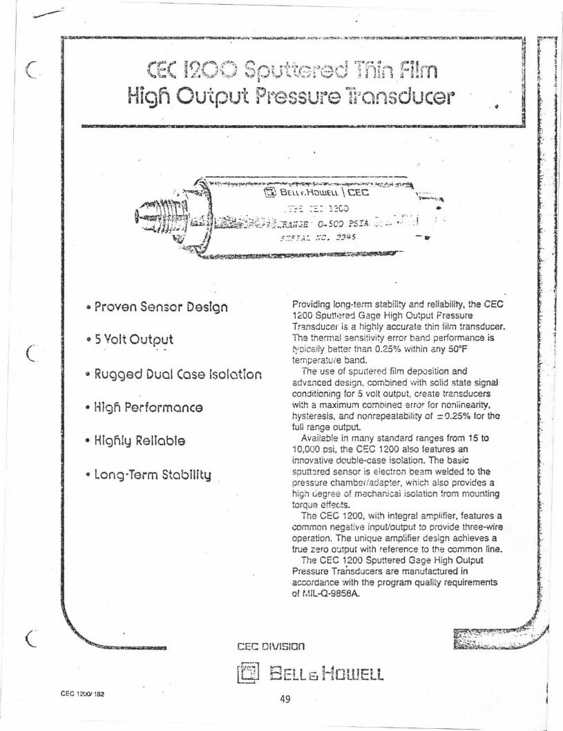
c. »w 11 lit 11 ur
Proven Sensor Design
* 5 Volt Output
• Rugged Duoi Case Isolation
• HIgfi Performance
• Highly Reliable
Long-Term Stability
c
Providing long-term stability and reliability, the CEC1200 Sputtered Gage High Output PressureTransducer is a highly accurate thin film transducer.The thermal sensitivity error band performance istypically better than 0.2δ% within any SOTtemperature band.
The use of sputtered film deposition andadvanced design, combined with solid state signalconditioning for 5 volt output, create transducerswith a maximum combined error for noniinearity,hysteresis, and nonrspeatability of -0.25% for thefull range output
Available in many standard ranges from 15 to10.0Q0 psi, the CEC 1200 also features aninnovative double-case isolation. The basicsputt3fed sensor is electron beam welded to thepressure chamber/adapter, which also provides ahigh degree of meehanicai isolation from mountingtorque effects.
The CEC 1200, with integral amplifier, features acommon negative input/output to provide three-wireoperation. The unique amplifier design achieves atrue zero output with reference to the common line.
The CEC 1200 Sputtered Gage High OutputPressure Transducers are manufactured inaccordance with the program quality requirementsof MIL-Q-9858A.
C c C
@ BELLaHDUIELLCEC 1200/182
49

SPECIFICflTIOnS
CcC 12OO Sputterθd Tfiln Film HIgfi Output Pressure Transducer
Pressure RatfngStandard Ranges:
Proof Pressure:
Burst Pressure:
0-15. 25. 50. 100. 250. 500, 1000.1500. 2000. 2500. 5000 and 10,000pst, absolute or gage. Sealed gageavailable in ranges of 100 psi andabove.200% of rated pressure, not to exceed15.000 psi.300% of rated pressure, not to exceed20.000 psi.
Electrlco! Characteristics
Excitation:Input Current:Full Range Ouptut:Residual Unbalance:Output Impedance:Combined Noniinearity,Hysteresis, andNonrepeatability:Insulation Resistance:Electrical Connector:
12 to 30 Vdc unregulated.20 mA maximum.5.0 Vdc =0.1 Vdc.« = 2 % FRO.100 ohms nominal.
= 0.25% FRO.^ 100 megohms at 45 Vdc.See drawing.
fflecftαnlcol Characteristics
Pressure Chamber MatenaJ:Pressure Fitting:Mounting Isolation:
Sensing Element:Weight:
17-4 PH stainless steel.7/16-20 male, flared. •T
Double case isolation provides assur-ance that the sensing eiemsπt wit! beunaffected by external stress.4 active-arm bridge.7 ounces maximum.
environmental Performance
Temperature:Operating Range:Compensated Range:Thermal Zero Shift:
Thermal Sensitivity Shift:
Combined Thermal Zeroand Sensitivity Shift:
Vibration Sensitivity:
Natural Frequency:
SlHXfc
Humidiiy:
flccessortes
Included:Optional:
- 4 f > F t o +185'F.-20 £ Fto + 1 5 0 ^ .= 0.005% FRO'F nominal over thecompensated temp, range.= 0.005% FRO^F nominal over the
compensated temp, range.0.3% over the compensated tempera-ture range.At 35g peak from 10 to 2000 Hz ( VD A max.) the output shall not exceed0.04% FRO σ for 1S psi units, de-creasiπα logarithmically to less than0.002%"- FRQ•g for 10,000 psi units.50 kHz at 5000 psi, decreasing logar-ithmically to 5 kHz aM 5 psi.Withstands 100g, 11 msec duration,half sine wave without damage.Per MIL-E-5272C, Procedure 1.
Calibration record and dust caps.Mating eiectrica! connecter. (SpecifyCEC part number 166267-0005.)
CSC á & rtgst rvd trstóβtnartc ol E«a A HoweJ
Pn:i»f<cl Λ U S A
Ordering Information:When ordering, specify the instruments complete type number,pressure range desired and whether absolute, gage, or sealed gageunit is required. (Example: CEC 1200 pressure transducer, 0-100psia.)
In keeping with Bell & HcweH's policy of continuing product improve-ment, specifications may be changed without notice. If the perform-ance and configuration provided herein for our standard product deesnot fit your exact needs, please check with us regarding customizedtransducers. Contact us directly at the factory or throuoh your nearestCEC Sales Office.
FUNGI !0N+ 12 to + 30V (*IN)+ OUTPUT- OUTPUT ,^,- INPUT
NO CONNECTION
SCHEMAT
I
Heceptactop-•!!>€? (101)'or
etjutvaiβni. M Λ Π Ç α•>πr ecrrEflndn FTSO6A-fθ-6S (S<^W
j (Net supplied)
CEC Division560 Sierra Madre V.üa. Pasadena, California91109 (213) 796-9381
50
-Λ.

APPENDIX C
Transducer Calibrations
52

o METROX
METROX INC.7165 CONSTRUCTION COURTSAN DI€GO.CA 92121(714) 271-1731
CALIBRATION DATA
Instrument: CEG
Certified by:
Equipment:—.
Date:
P (f*ò3SP ö/C>or>
(t 000
frooa
-J 00 nZ•K• /Cú
looo2.0 003 000
U OOP
. OO9A-
‰cZO1,5307.030
f. 030, C3o
P
S& GO
trOOO
JTooOhnoc>
1 &<o 0
0
a
O
a
0
S3.V
* S~fOf.nl4-^ srit,
/. r2.ö/ O-2-O •
.005:3.
P>
JpCX3O
(0000
on <s*
Vr .497^
/» -94-/ 9 93
2..9 9O0
, »•>
•erv
.O3H
Full scale sensitivity:
Shunt calib. data:
54

APPENDIX D
MEASURED DATA
56

P\PtPUJG
DO NOT SCALE
TOLERANCESUNLESS NOTED
FRACTIONS i 1/64
DECIMALS t .005
ANGLES i 1/2°
CORNERS 1/64x45°or 1/64 R
FINISH
SURFACE TREATMENT
θ
HEAT TREATMENTθ
CONCENTRICITY ALL DIAMETERS'. TIR .003
DEEP SEA DRILLING PROJECTSCRIPPS INSTITUTION OF OCEANOGRAPHY
UNIVERSITY OF CALIFORNIA, SAN DIEGO
LA JOLLA. CALIFORNIA
TITLE
MATERIAL
SCALE REQD/ASS•Y
^•" •a ILKPART NO.
O P 5S 2>O-I
CHECKED
92093
DWG. NO. (REV.)
Sπε 6/Q - kiAs/< 3 ftflg^s k r ^ a J CnR& Iti+ft


PRESSURE MEASURING TOOL
70 7i -; 7i rt :• •t )• . .» g(| ai t i βi M is •«. «? a« r> QQ •n •>•> «Λ »< . i H v> i » 1
BOTTOMCAP
PRESSURETUBING
PRESSURETRANSDUCERS
ELECTRONICSPACK
BATTERYPACK
SHOCKINDICATOR
L\
SHOCKABSORBER

![Scientific Ocean Drilling: Accomplishments and … · Drilling Program [ODP, 1984–2003], and Integrated Ocean Drilling Program [IODP, 2003–2013]), have spurred remarkable progress](https://img.pdfslide.net/doc/110x75/5b8e23e609d3f2187e8d2095/scientific-ocean-drilling-accomplishments-and-drilling-program-odp-19842003.jpg)