Embed Size (px)
Citation preview

International Research Journal of Engineering and Technology (IRJET) e-ISSN: 2395 -0056
Volume: 04 Issue: 02 | Feb -2017 www.irjet.net p-ISSN: 2395-0072
© 2017, IRJET | Impact Factor value: 5.181 | ISO 9001:2008 Certified Journal | Page 395
Modeling and Analysis of Car Wheel
Gamachisa Mitiku Tadesse Department of Mechanical Engineering, Asst Lecturer
Bule hora University, Ethiopia ---------------------------------------------------------------------------***---------------------------------------------------------------------------------
ABSTRACT: - The automotive industry is a
significant lifeline of the country’s economic
activity. About 90 per cent of vehicles are owned
and operated by individual operators. A large
majority of the four wheelers are constructed by
units in semi-organized / organized sectors
spread over the country. There is considerable
scope to improve the design of their products.
There are different types of wheels bodies
available such as Steel, Aluminum, Magnesium,
Titanium, etc. In Regular commercial vehicles
steel wheels are generally used. For steel corrosive
resistance, thermal conductivity, weight, casting
and machining properties are low compared to
aluminum alloy. In the design of automobile, the
industries are using aluminum alloy material in
order to obtain reduction of weight without
significant decrease in vehicle quality and
reliability. This is due to the fact that the
reduction of weight of a vehicle directly impacts
its fuel consumption. With this concept of reducing
weight and stress reduction the wheel is modeled
and analyzed. In this project, Aluminum alloy is
compared with steel. In this project a parametric
model is designed for steel wheel from existing
model. The wheel model is modeled in CAD
package CATIA and Static structural, Modal and
Fatigue analysis are done in FEA package ANSYS
WORKBENCH for Steel and Aluminum Alloy
A356.2 materials. By conducting the Finite
Element Analysis on the wheel Model the results of
Steel and Aluminum Alloy wheel were presented.
When compared Aluminum alloy wheel has better
results than Steel wheel. Introduction
The work observed that a fatigue lifetime prediction method of Aluminum alloy wheels was proposed to ensure their durability at the initial design stage. To simulate the rotary fatigue test, static load FEM model was built using ABAQUS. The analysis results showed that the maximum stress area was located in the hub bolt whole area agreed with the fact. Therefore, the finite element model can achieve results consistent with that obtained from the actual static load test [1]. The fatigue lifetime prediction method of alloy wheels was proposed to ensure their durability at the initial design stage. To simulate the rotary fatigue test, static load FEM model was built using COSMOS. The analysis results showed that the maximum stress area was located in the hub bolt whole area agreed with the fact. Therefore, the finite element model can achieve results consistent with that obtained from the actual static load test. The nominal stress method was used to predict the fatigue life of alloy wheels. In the nominal stress method, the fatigue life of alloy wheels was predicted by using alloy wheel S-N curve and equivalent stress amplitude. The simulation result showed that baseline design fatigue life was lower than. After improving the weakness area of alloy wheels, the improved wheel life cycle exceeded 1*105 and satisfied the design requirement [2] .CAD model of the wheel rim is generated in CATIA and this model is imported to ANSYS for processing work. An amount of pressure 200 kpa is applied along the circumference of the wheel rims made of both Aluminum and forged steel and bolt circle of wheel rim is fixed [3]. Static and fatigue analysis of Aluminum alloy wheel A356.2 was carried out using FEA package. The 3 dimensional model of the wheel was designed using CATIA. Then the 3-D model was imported into ANSYS using the IGES format. The finite element idealization of this modal was then produced using the 10 node tetrahedron solid element. The analysis was performed in a static condition. This is constrained in all degree of freedom at the PCD and hub portion. The pressure is applied on the rim. Their results obtained are total deformation, alternative stress and shear stress by using FEA software. And also they find out the life, safety factor

International Research Journal of Engineering and Technology (IRJET) e-ISSN: 2395 -0056
Volume: 04 Issue: 02 | Feb -2017 www.irjet.net p-ISSN: 2395-0072
© 2017, IRJET | Impact Factor value: 5.181 | ISO 9001:2008 Certified Journal | Page 396
and damage of alloy wheel by using S-N curve. S-N curve is input for a A.356.2 material [4]. A detailed static and fatigue analysis of Aluminum alloy wheel under a radial loads has been done. Analysis of Aluminum alloy wheel A356.2 was carried out using FEA package. The 3 dimensional model of the wheel was designed using CATIA. Then the IGES format 3-D model was imported into ANSYS. Their thesis summarizes the application of finite element analysis technique for analyzing stress distribution and fatigue life of Aluminum alloy wheels subject to radial loads. Alloy wheels intended for use on passenger cars stipulate two types of fatigue tests, the dynamic cornering fatigue test and the dynamic radial fatigue test. As wheels undergo inconsistent, varying loads during their service life, fatigue behavior is a key consideration in the design and performance evaluation. But since alloy wheels are designed for styling and have more complex shapes than regular steel wheels, it is difficult to assess fatigue life by analytical methods. So, finite element analysis has been used to evaluate the performance of wheels over their life [5]. The entire wheel design of two wheeler was chosen and analyzed by applying different load and redesign the wheel again to minimize the deformation and material will be changed from Aluminum to PEEK (polyether ether ketone) the whole design is made by using NX 7.5. The whole design has been made as per original equipment manufacturer (OEM’S) requirement. Analysis has been done by Ansys 13.0 software to determine the various stresses, strain and fatigue life of the wheel [6]. At seeking a practical and comprehensive method for simulating the dynamic cornering fatigue test of the automotive wheels. The test of a steel passenger car wheel is simulated by combined use of the linear transient dynamic finite element analysis and the local strain approach. A rotating force of constant magnitude is applied to the moment arm tip to simulate the rotating bending effect on the wheel, with the wheel stationary. It is found that only a radial component of the rotating force is needed to obtain the sufficiently accurate radial normal strain histories of the elements located along the radial direction. The strain history of the element whose local stress–strain characteristic keeps linear and closest to the critical element is applied to predict the fatigue life of the critical element with Neuber’s rule and local strain approach, which is quite close to the test results [7].
PROBLEM DESCRIPTION
DESCRIPTION
The steel wheel is a mechanical device, which provides rotary motion by means of a disk or circular frame revolving on an axis. The steel wheel can be used in heavy load and traction services. The size and contour of a specific wheel design is based on the load it must carry and the space limitations of the equipment on which it are used. The contour of the wheel is normally composed compose of five parts: the hub, plate, rim, tread and flange. Today, the steel wheel has been partially replaced by the Aluminum alloy wheel on vehicles, and this trend is expected to continue and become more popular in the near future. There are at least four good reasons why wheel industries now prefer to use Aluminum alloy to replace wrought steel: Aluminum alloy wheels are more loads worthy. Excellent brake system. Aluminum thermal conductivity is about three times higher than that of steel this physical property gives the wheel better brake reliability and longer life than the steel wheel; it is fuel-efficient. Suspension improvements. The suspension system of Aluminum alloy wheels is capable of responding much more quickly to changing surfaces and road conditions. This increased traction can improve vehicle acceleration, maneuverability and brake performance. It is particularly noticeable while driving at high speeds or on rough roads.
METHODOLOGY The methodology of work is Geometric modeling of a wheel in CATIA. Static analysis for steel wheel existing model under loading conditions. In order to solve the problem of the project, a detailed finite element analysis is proposed to determine the total deformation and Equivalent stress in static condition using the analysis software ANSYS WORKBENCH. Modal analysis for steel wheel existing model under loading conditions. In order to solve the problem of the project, a detailed finite element analysis is proposed to determine the total deformation under frequencies at each mode using the analysis software ANSYS WORKBENCH. Fatigue analysis for steel wheel existing model under loading conditions In order to solve the problem of the project, a detailed finite element analysis is proposed to determine equivalent alternative stress, factor of safety, fatigue life using the analysis software ANSYS WORKBENCH. The above three analysis are repeated for Aluminum alloy wheel. After analyzing the two materials are compared.

International Research Journal of Engineering and Technology (IRJET) e-ISSN: 2395 -0056
Volume: 04 Issue: 02 | Feb -2017 www.irjet.net p-ISSN: 2395-0072
© 2017, IRJET | Impact Factor value: 5.181 | ISO 9001:2008 Certified Journal | Page 397
MECHANICAL PROPERTIES
Modeling and Analysis The wheel body under consideration is generated in the CATIA CAD Modeling package. It is a powerful program used to create complex designs with great precision. It has properties like Feature-based nature, Bidirectional associative property and parametric nature. Parametric features are helpful in reusing wheel model of car body to create new variant design. The CATIA file is saved in *.IGES format (Initial Graphics Exchange Specification) is an exchange for product data in support of industrial automation. The general emphasis of IGES is to eliminate the human presence from the “product data”. The central unit of data exchange in the IGES model is the application, which contains various types of entities. This approach maintains all the meaningful associative and relationships between the application entities. Therefore IGES is to represent all product information, in a common data format, throughout a product’s entire life cycle. SOLUTION
6.4.5.1FOR STEEL WHEEL
6.4.5.1.1 Modal analysis Results
In this modal analysis no loading conditions are
considered
Figure6.7.1
Figure 6.7.2
Figure 6.7.3
Figure 6.7.4

International Research Journal of Engineering and Technology (IRJET) e-ISSN: 2395 -0056
Volume: 04 Issue: 02 | Feb -2017 www.irjet.net p-ISSN: 2395-0072
© 2017, IRJET | Impact Factor value: 5.181 | ISO 9001:2008 Certified Journal | Page 398
Figure 6.7.5
Figure 6.7.6
Figure 6.7 Total Deformation of steel wheel with
various frequencies
6.4.5.2FOR ALUMINUM ALLOY A356.2 WHEEL
6.4.5.2.1 Modal analysis Results
In this modal analysis no loading conditions are
considered
Figure 6.8.1
Figure 6.8.2
International Research Journal of Engineering and Technology (IRJET) e-ISSN: 2395 -0056
Volume: 04 Issue: 02 | Feb -2017 www.irjet.net p-ISSN: 2395-0072
© 2017, IRJET | Impact Factor value: 5.181 | ISO 9001:2008 Certified Journal | Page 399
Figure 6.8.3
Figure6.8.4
Figure 6.8.5
Figure 6.8 Total Deformation of Aluminum Alloy A356.2 wheel with various frequencies
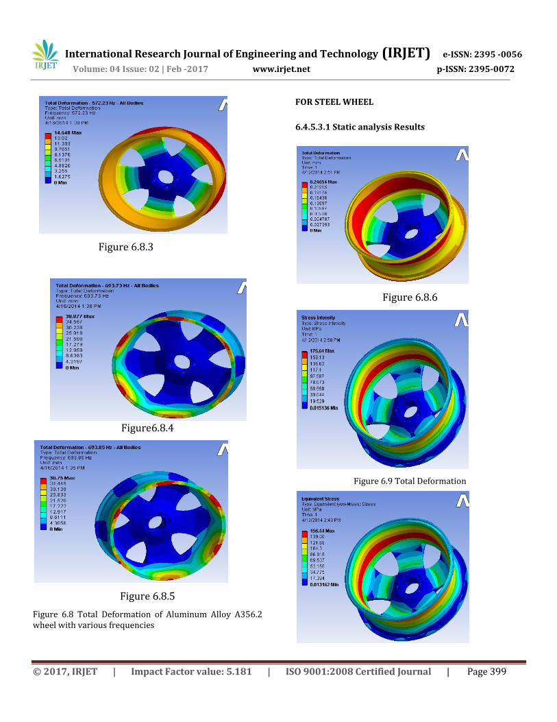
FOR STEEL WHEEL
6.4.5.3.1 Static analysis Results
Figure 6.8.6
Figure 6.9 Total Deformation

International Research Journal of Engineering and Technology (IRJET) e-ISSN: 2395 -0056
Volume: 04 Issue: 02 | Feb -2017 www.irjet.net p-ISSN: 2395-0072
© 2017, IRJET | Impact Factor value: 5.181 | ISO 9001:2008 Certified Journal | Page 400
Figure 6.10 Stress Intensity
Total
Deformation
Maximum
(mm)
Stress
Intensity(Mpa)
Equivalent
Stress(Mpa)
Max Min Max Min
0.2464 175.64 0.0151 156.44 0.0131
Table 6.5 Static analysis Results for Steel Wheel
6.4.5.4 FOR ALUMINUM ALLOY A356.2 WHEEL
6.4.5.4.1 Static Analysis Results
Figure 6.12 Total Deformation
Figure 6.13 Stress Intensity
Figure 6.14 Equivalent Stress
Table 6.6 Static analysis Results for Aluminum Alloy
A356.2 Wheel
6.4.5.5FOR STEEL WHEEL
6.4.5.5.1 Fatigue Analysis Results
Figure 6.15 Life Figure
Table 6.7 Fatigue Analysis Results for Steel
Wheel

International Research Journal of Engineering and Technology (IRJET) e-ISSN: 2395 -0056
Volume: 04 Issue: 02 | Feb -2017 www.irjet.net p-ISSN: 2395-0072
© 2017, IRJET | Impact Factor value: 5.181 | ISO 9001:2008 Certified Journal | Page 401
Figure 6.17 Graph Based On Alternative Stress Vs
Cycles For steel wheel
6.4.5.6 FOR ALUMINUM ALLOY A356.2 WHEEL
6.4.5.6.1 Fatigue Analysi s Results
Figure 6.18 Life
Figure 6.19 Equivalent alternating stresses
Figure 6.20 Graph Based on Alternative Stress Vs Cycles of
Aluminum Alloy A356.2 Wheel
7.1 RESULTS AND DISCUSSION
The wheel is analyzed in ANSYS WORKBENCH for two materials. The obtained results are compared. Better results are obtained for Aluminum Alloy A356.2 when compared to Steel. The results of two materials of wheel are shown in Table 7.1
STEEL ALUMINUM
ALLOY A356.2
MASS (Kgs)
30.667 10.825
TOTAL DEFORMATION
MAXIMUM (MM) 0.2464 0.2468
EQUIVALENT STRESS (MPa)
156.44 156.33
STRESS INTENSITY (MPa)
175.64 175.59
LIFE IN CYCLES
MAX 1e6 1e8
MIN 63281 3.3e5
EQUIVALENT ALTERNATING
STRESS (MPa)
156.33 155.34

International Research Journal of Engineering and Technology (IRJET) e-ISSN: 2395 -0056
Volume: 04 Issue: 02 | Feb -2017 www.irjet.net p-ISSN: 2395-0072
© 2017, IRJET | Impact Factor value: 5.181 | ISO 9001:2008 Certified Journal | Page 402
Table7.1 Comparison of results of Steel and Aluminum
Alloy A356.2 materials for wheel
CONCLUSIONS
By conducting the FEM Analysis on Steel and Aluminum Alloy A356.2 wheels weight reduction and stress reduction is done.For Aluminum Alloy A356.2 wheel stress analysis is carried out and the equivalent stress is 156.33MPa and total deformation is 0.2468mm is obtained. Weight reduction of Aluminum Alloy A356.2 wheel comparing with the Steel wheel is 60%. By weight reduction, fuel efficiency and braking effect of the vehicle is improved. By material change the life time of the wheel is improved. REFERENCES
[1.] Liangmo Wang, Yufa Chen, Chenzhi Wang, Qingzheng Wang, Fatigue Life Analysis of Aluminum Wheels by Simulation of Rotary Fatigue Test, Journal of Mechanical Engineering, Volume 57, 2011
[2.] S Vikranth Deepak, C Naresh and Syed Altaf Hussain, International Journal of Mechanical Engineering and Robotics Reasearch, Volume 1, 2012
[3.] P. Meghashyam, S. Girivardhan Naidu and N. Sayed Baba, International Journal of Application or Innovation in Engineering & Management, Volume 2, 2013
[4.] N. Satyanarayana & Ch.Sambaiah, International Journal of Mechanical and Industrial Engineering, Volume2 , 2012
[5.] Subba Rao Vlisi And Tippa Bhimasankar Rao, International Journal of Mathematical Sciences, Technology and Humanities, Volume 64, 2012
[6.] Ravi Lidoriya, SanjayChaudhary and Anil Kumar Mohopatra, International Journal of Mechanical Engineering and Research, Volume 3, 2013
[7.] Currie and Wilson, Finite Element Analysis of an Automotive Wheel—A Case History, National Conference Publication, Institution of Engineers, Australia, pp. 16–20, April 1981.
[8.] Institution of Mechanical Engineers, Ed., Automobile Wheels and Tyres, Institution of Mechanical Engineers, Ed., I. Mech. E Conference Publications, Conference Code 03757, London, UK, December 1983.
[9.] M. Reisner and R. DeVries, “Finite Element Analysis and Structural Optimization of Vehicle Wheels,” SAE Technical Paper Series, pp20.
[10.] N. Mizoguchii and A. Nishimura, “Stress analysis and fatigue strength of sheet fabricated Aluminum wheels,” R & D Magazine, vol. 32, no. 2, pp. 8–12, 1982.
[11.] M. Kawashima, “Stress evaluation of automotive steel road wheel under radial load,” Transactions of the Japan Society of Mechanical Engineers, Part C, vol. 55, no. 513, pp. 1254–1258, 1989.
[12.] K. Morita and M. Kawashima, “Finite element stress analysis of a car wheel,” Sumitomo Metals, vol. 39, no. 3, pp. 245–263, 1987
[13.] K. Morita and K. Ishihara, “Finite element analysis of a steel car wheel,” Sumitomo Search, no. 35, pp. 89–106, 1987.
[14.] J. A. Sherwood, B. K. Fussell, W. R. Edwards, T. S. Gross, and D. W. Watt, “Study of the pressure distribution on an aircraft tire-wheel interface,” Journal of Aircraft, vol. 32, no. 5, pp. 921–928, 1995.