Embed Size (px)
Citation preview
© HAKI AB 2015
HAKI UNIVERSALInternat ional version
USER´S MANUAL
2
© Copyright HAKI AB, 2015The reproduct ion of text and pictures/illustrat ions without HAKI’s permission is prohibited.
Important informationHAKI’s product liability and user´s manuals apply only to scaffolds that areentirely composed of components that have been made and supplied by HAKI.
HAKI’s type examination certifi cate apply only to scaffolds whose materials,dimensions and design accord with those specifi ed in the documentation uponwhich this certifi cate is based.
HAKI’s scaffold systems must not be erected using components of makes otherthan HAKI or be connected to scaffolds of makes other than HAKI. In such cases,a special study of load-bearing capacity must be carried out. However, HAKI hasno objection to the customary addition of scaffold tubes and approved couplersto the scaffold.
Adding components from different suppliers may invalidate the insurance cover.
HAKI reserves the right to make technical modifi cations on a continual basis.
A user’s manual should be provided to the user together with the scaffolding.
The latest versions of HAKI user’s manuals can be downloaded from our website,www.HAKI.com.
For scaffold structures that are not covered by this user´s manual, pleasecontact HAKI’s technical department.
Forces and dimensions 1000 N = 1 kN ~ 100 kg 10 N ~ 1 kgAll measurements in mm
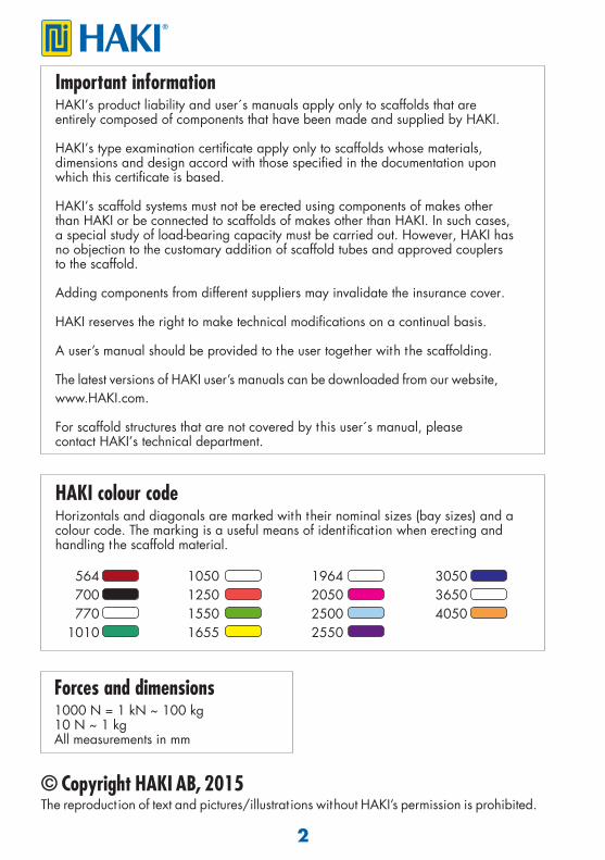
HAKI colour codeHorizontals and diagonals are marked with their nominal sizes (bay sizes) and a colour code. The marking is a useful means of ident ifi cat ion when erect ing and handling the scaffold material.
564 1050 1964 3050 700 1250 2050 3650 770 1550 2500 4050 1010 1655 2550
3
BASIC INFORMATION
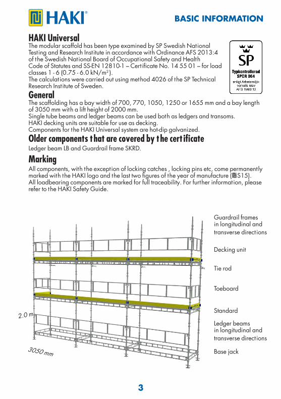
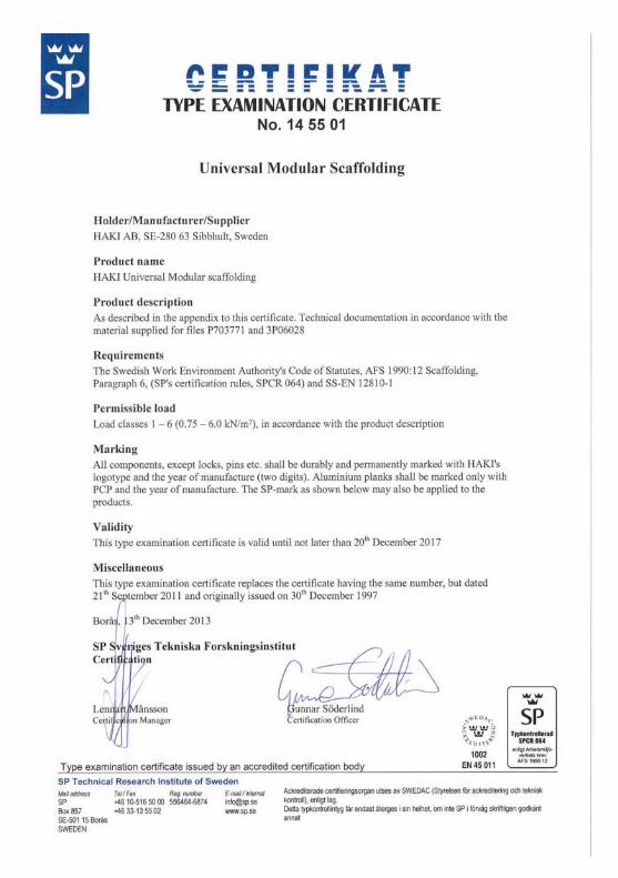
HAKI Universal The modular scaffold has been type examined by SP Swedish NationalTest ing and Research Inst itute in accordance with Ordinance AFS 2013:4of the Swedish National Board of Occupational Safety and HealthCode of Statutes and SS-EN 12810-1 – Cert ificate No. 14 55 01 – for loadclasses 1 - 6 (0.75 - 6.0 kN/m2 ). The calculat ions were carried out using method 4026 of the SP TechnicalResearch Inst itute of Sweden.General The scaffolding has a bay width of 700, 770, 1050, 1250 or 1655 mm and a bay length of 3050 mm with a lift height of 2000 mm.Single tube beams and ledger beams can be used both as ledgers and transoms.HAKI decking units are suitable for use as decking. Components for the HAKI Universal system are hot-dip galvanized.Older components that are covered by the cert ificateLedger beam LB and Guardrail frame SKRD.
MarkingAll components, with the exception of locking catches , locking pins etc, come permanent ly marked with the HAKI logo and the last two figures of the year of manufacture ( S15). All loadbearing components are marked for full traceability. For further information, please refer to the HAKI Safety Guide.
Guardrail framesin longitudinal andtransverse direct ions
Decking unit
Tie rod
Toeboard
Standard
Ledger beamsin longitudinal and transverse direct ions
Base jack 3050 mm
2.0 m
4
LIST OF COMPONENTS
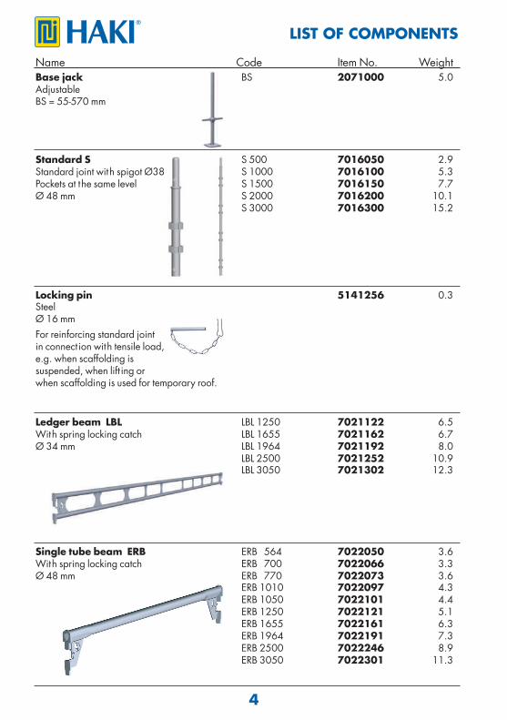
Name Code Item No. WeightBase jack BS 2071000 5.0 Adjustable BS = 55-570 mm
Standard S S 500 7016050 2.9 Standard joint with spigot Ø38 S 1000 7016100 5.3Pockets at the same level S 1500 7016150 7.7Ø 48 mm S 2000 7016200 10.1 S 3000 7016300 15.2
Locking pin 5141256 0.3 SteelØ 16 mmFor reinforcing standard joint in connect ion with tensile load,e.g. when scaffolding issuspended, when lift ing orwhen scaffolding is used for temporary roof.
Ledger beam LBL LBL 1250 7021122 6.5 With spring locking catch LBL 1655 7021162 6.7 Ø 34 mm LBL 1964 7021192 8.0 LBL 2500 7021252 10.9 LBL 3050 7021302 12.3
Single tube beam ERB ERB 564 7022050 3.6With spring locking catch ERB 700 7022066 3.3Ø 48 mm ERB 770 7022073 3.6 ERB 1010 7022097 4.3 ERB 1050 7022101 4.4 ERB 1250 7022121 5.1 ERB 1655 7022161 6.3 ERB 1964 7022191 7.3 ERB 2500 7022246 8.9 ERB 3050 7022301 11.3
5
LIST OF COMPONENTSName Code Item No. Weight
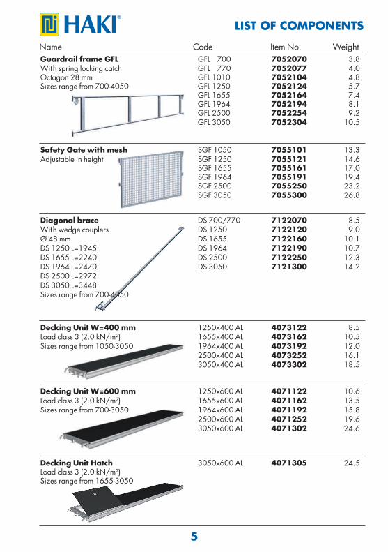
Diagonal brace DS 700/770 7122070 8.5 With wedge couplers DS 1250 7122120 9.0Ø 48 mm DS 1655 7122160 10.1DS 1250 L=1945 DS 1964 7122190 10.7DS 1655 L=2240 DS 2500 7122250 12.3DS 1964 L=2470 DS 3050 7121300 14.2DS 2500 L=2972 DS 3050 L=3448Sizes range from 700-4050
Decking Unit W=600 mm 1250x600 AL 4071122 10.6Load class 3 (2.0 kN/m²) 1655x600 AL 4071162 13.5 Sizes range from 700-3050 1964x600 AL 4071192 15.8 2500x600 AL 4071252 19.6 3050x600 AL 4071302 24.6
Guardrail frame GFL GFL 700 7052070 3.8With spring locking catch GFL 770 7052077 4.0Octagon 28 mm GFL 1010 7052104 4.8 Sizes range from 700-4050 GFL 1250 7052124 5.7 GFL 1655 7052164 7.4 GFL 1964 7052194 8.1 GFL 2500 7052254 9.2 GFL 3050 7052304 10.5
Decking Unit W=400 mm 1250x400 AL 4073122 8.5Load class 3 (2.0 kN/m²) 1655x400 AL 4073162 10.5 Sizes range from 1050-3050 1964x400 AL 4073192 12.0 2500x400 AL 4073252 16.1 3050x400 AL 4073302 18.5
Decking Unit Hatch 3050x600 AL 4071305 24.5Load class 3 (2.0 kN/m²) Sizes range from 1655-3050
Safety Gate with mesh SGF 1050 7055101 13.3 Adjustable in height SGF 1250 7055121 14.6 SGF 1655 7055161 17.0 SGF 1964 7055191 19.4 SGF 2500 7055250 23.2 SGF 3050 7055300 26.8
6
LIST OF COMPONENTS
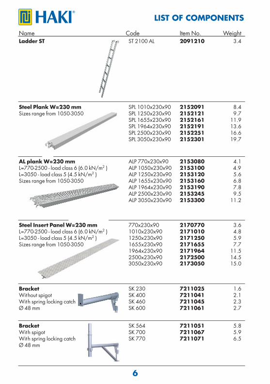
Name Code Item No. WeightLadder ST ST 2100 AL 2091210 3.4
AL plank W=230 mm ALP 770x230x90 2153080 4.1L=770-2500 - load class 6 (6.0 kN/m2 ) ALP 1050x230x90 2153100 4.9L=3050 - load class 5 (4.5 kN/m2 ) ALP 1250x230x90 2153120 5.6Sizes range from 1050-3050 ALP 1655x230x90 2153160 6.8 ALP 1964x230x90 2153190 7.8 ALP 2500x230x90 2153245 9.5 ALP 3050x230x90 2153300 11.2
Steel Plank W=230 mm SPL 1010x230x90 2152091 8.4Sizes range from 1050-3050 SPL 1250x230x90 2152121 9.7 SPL 1655x230x90 2152161 11.9 SPL 1964x230x90 2152191 13.6 SPL 2500x230x90 2152251 16.6 SPL 3050x230x90 2152301 19.7
Steel Insert Panel W=230 mm 770x230x90 2170770 3.6L=770-2500 - load class 6 (6.0 kN/m2 ) 1010x230x90 2171010 4.8L=3050 - load class 5 (4.5 kN/m2 ) 1250x230x90 2171250 5.9Sizes range from 1050-3050 1655x230x90 2171655 7.7 1964x230x90 2171964 11.5 2500x230x90 2172500 14.5 3050x230x90 2173050 15.0
Bracket SK 230 7211025 1.6Without spigot SK 400 7211041 2.1With spring locking catch SK 460 7211045 2.3Ø 48 mm SK 600 7211061 2.7
Bracket SK 564 7211051 5.8With spigot SK 700 7211067 5.9With spring locking catch SK 770 7211071 6.5Ø 48 mm
7
LIST OF COMPONENTS
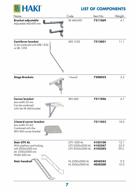
Corner bracket SKH 460 7211046 6.7Jaw width 22 mm Can be combined with the SK 460 bracket
Name Code Item No. Weight
Stage Brackets 1 board 7208032 3.5
Cantilever bracket SKD 1250 7212001 11.1To be combined with ERB 1250 or LBL 1250
Bracket adjustable SK 460-690 7211069 4.1Adjustable 460-690 mm
Stair UTV AL UTV 1000 AL 4102100 12.1With plat form and locking UTV 2500x2000 AL 4102247 22.9 LxH 3050x2000 mm UTV 3050x2000 AL 4102302 29.2 alt. 2500x2000 mmWidth 600 mm Stair handrail HL 2500x2000 AL 4058245 9.2 HL 3050x2000 AL 4058300 10.3
3 board corner bracket 7211053 18.0Jaw width 22 mm Combined with theSKH 460 corner bracket
8
LIST OF COMPONENTS
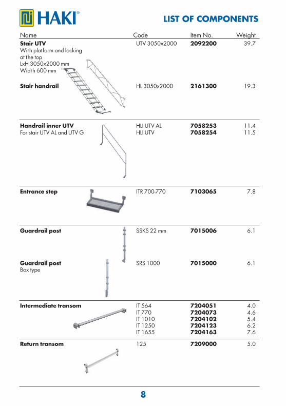
Name Code Item No. WeightStair UTV UTV 3050x2000 2092200 39.7With plat form and locking at the top LxH 3050x2000 mmWidth 600 mm Stair handrail HL 3050x2000 2161300 19.3
Handrail inner UTV HLI UTV AL 7058253 11.4For stair UTV AL and UTV G HLI UTV 7058254 11.5
Guardrail post SSKS 22 mm 7015006 6.1
Guardrail post SRS 1000 7015000 6.1Box type
Entrance step ITR 700-770 7103065 7.8
Intermediate transom IT 564 7204051 4.0 IT 770 7204073 4.6 IT 1010 7204102 5.4 IT 1250 7204123 6.2 IT 1655 7204163 7.6
Return transom 125 7209000 5.0
9
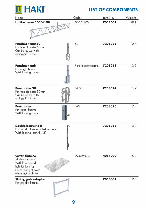
Lattice beam 500/6100 500/6100 7031602 59.1
LIST OF COMPONENTSName Code Item No. Weight
Cover plate AL 995x495x4 4011000 5.2AL checker plateWith handle and hole for lashingFor covering of holes when laying planks
Sliding gate adaptor 7053001 9.4For guardrail frame
Puncheon unit 50 50 7208025 2.7For tube diameter 50 mmCan be locked with spring pin 12 mm
Puncheon unit Puncheon unit same 7208018 3.9For ledger beamsWith locking screw
Beam rider 50 BR 50 7208024 1.2For tube diameter 50 mmCan be locked with spring pin 12 mm
Beam rider BRS 7208020 2.7For ledger beamsWith locking screw
Double beam rider 7208033 3.0For guardrail frame or ledger beamsWith locking screw N=21
10
LIST OF COMPONENTS
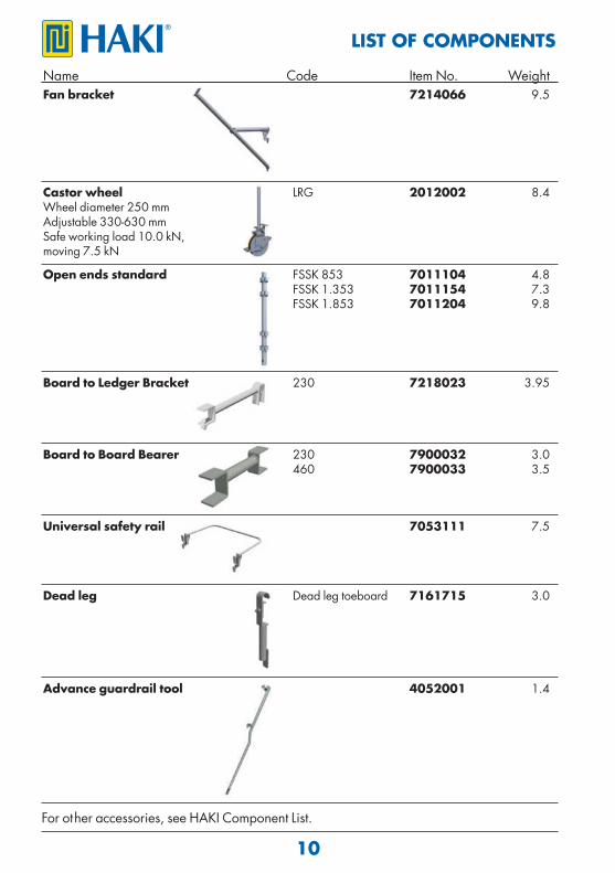
Name Code Item No. WeightFan bracket 7214066 9.5
Castor wheel LRG 2012002 8.4Wheel diameter 250 mmAdjustable 330-630 mmSafe working load 10.0 kN, moving 7.5 kN
Board to Ledger Bracket 230 7218023 3.95
Universal safety rail 7053111 7.5
For other accessories, see HAKI Component List.
Advance guardrail tool 4052001 1.4
Dead leg Dead leg toeboard 7161715 3.0
Board to Board Bearer 230 7900032 3.0 460 7900033 3.5
Open ends standard FSSK 853 7011104 4.8 FSSK 1.353 7011154 7.3 FSSK 1.853 7011204 9.8
11
Informat ion on safety when erect ing and dismant ling 1. Carry out local risk assessment and method statement. 2. Make sure that all lift ing equipment to be used, e.g chain hoists, lift ing ropes, pulley blocks, etc., has been thoroughly tested and approved by an authorised person in accordance with local regulat ions. 3. Check that tools and protect ive equipment are available at the worksite. 4. Wear appropriate personal safety equipment at all t imes, e.g. safety harnesses, proper independence lifelines with suitable fixings, etc. 5. When erect ing and dismant ling a scaffold, robust temporary decking must be used as temporary platforms for plat forms for the scaffolders. 6. Always make sure that the safety locking devices that prevent a plat form lift ing off have been act ivated once a platform has been installed. 7. Study all relevant instruct ions or safety direct ions from the manufacturers of the various scaffolds that are to be used. 8. Never climb up a scaffold from the outside. Always use the stairs, ladders or climbing frames that are designed to provide access to the upper decks from the inside of the scaffold. 9. If the scaffold is to be used outdoors, erect ion or dismant ling work must be discont inued of the weather condit ions are too bad. Make sure that all loose components are properly fixed before leaving the scaffold.10. Scaffolding work must be done by “competent operat ives” under the supervision of a “competent person”.11. Lift ing equipment must not be attached to a free-standing scaffold. 12. Beware of any overhead power lines nearby.13. Always observe and comply with the regulat ions issued by the local authorit ies concerned.
Instruct ions for dismant ling 1. Dismant le the scaffold from the topmost lift. 2. Start by taking down the toe boards. 3. Take down the topmost decking. 4. Take down the horizontals and diagonals of the topmost lift. 5. Finally remove the standards where possible. 6. Repeat 2-6 to take down the second topmost lift and continue the whole process unt il the dismant ling process reached the scaffold is completely dismant led. 7. Do not throw or drop materials to the ground. This may damage the material or cause personal injury. The materials must be lowered down to the ground by means of ropes or slings or passed down by hand. 8. If intermediate t ies or t ie rod tube have been installed, they must not be removed unt il the dismant ling process reaches the level in quest ion. 9. Always observe and comply with the regulat ions published by the local authorit ies concerned.10. Reference should also be made to the sect ion “Information on safety when erect ing and dismant ling” in this manual.
ERECTING/DISMANTLING SCAFFOLD
12
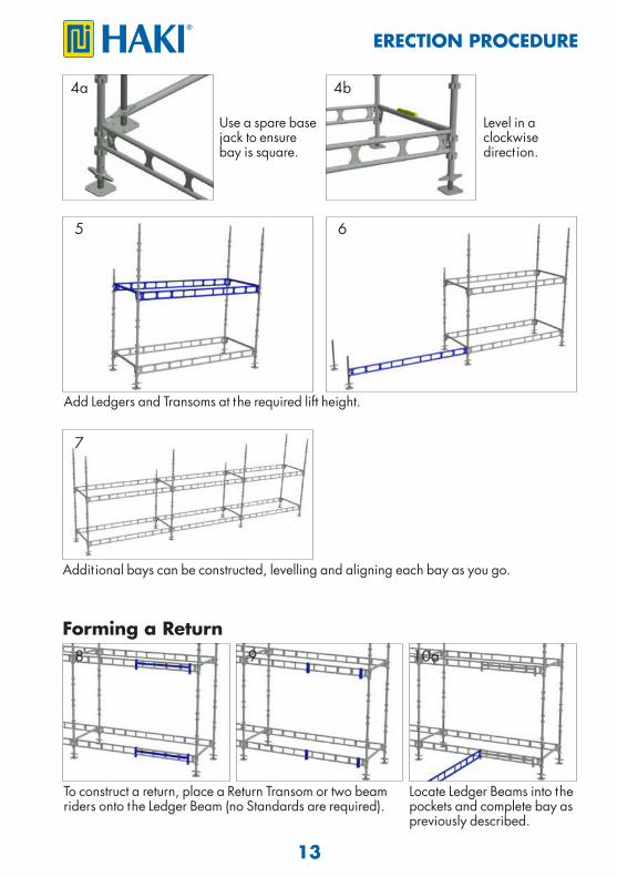
ERECTION PROCEDURE
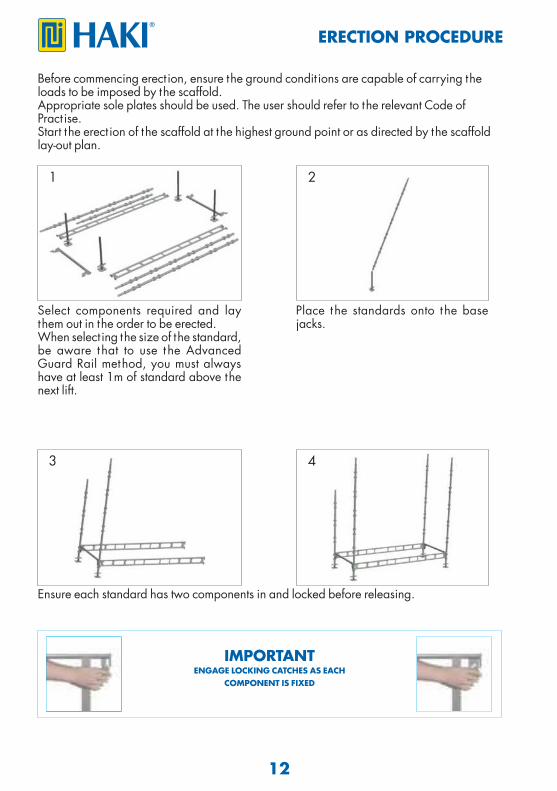
Before commencing erect ion, ensure the ground condit ions are capable of carrying the loads to be imposed by the scaffold.Appropriate sole plates should be used. The user should refer to the relevant Code of Pract ise. Start the erect ion of the scaffold at the highest ground point or as directed by the scaffold lay-out plan.
1 2
Select components required and lay them out in the order to be erected. When select ing the size of the standard, be aware that to use the Advanced Guard Rail method, you must always have at least 1m of standard above the next lift.
Place the standards onto the base jacks.
Ensure each standard has two components in and locked before releasing.
IMPORTANTENGAGE LOCKING CATCHES AS EACH
COMPONENT IS FIXED
3 4
13
ERECTION PROCEDURE
Use a spare base jack to ensure bay is square.
Addit ional bays can be constructed, levelling and aligning each bay as you go.
Add Ledgers and Transoms at the required lift height.
5 6
7
8
4a 4b
Level in a clockwise direct ion.
Forming a Return
To construct a return, place a Return Transom or two beam riders onto the Ledger Beam (no Standards are required).
Locate Ledger Beams into the pockets and complete bay as previously described.
9 10a
14
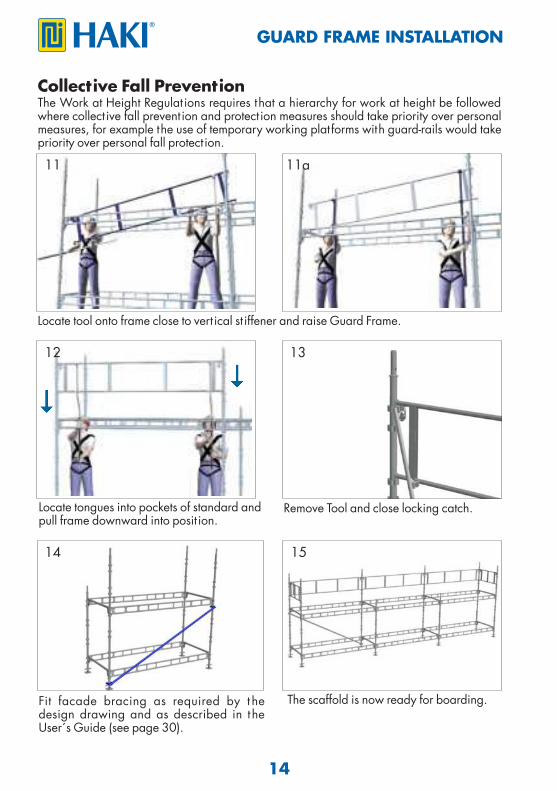
GUARD FRAME INSTALLATION
Collective Fall PreventionThe Work at Height Regulat ions requires that a hierarchy for work at height be followed where collect ive fall prevent ion and protect ion measures should take priority over personal measures, for example the use of temporary working platforms with guard-rails would take priority over personal fall protect ion.
Locate tool onto frame close to vert ical st iffener and raise Guard Frame.
11 11a
12 13
15
Remove Tool and close locking catch. Locate tongues into pockets of standard and pull frame downward into posit ion.
Fit facade bracing as required by t he design drawing and as described in the User´s Guide (see page 30).
The scaffold is now ready for boarding.
14
15
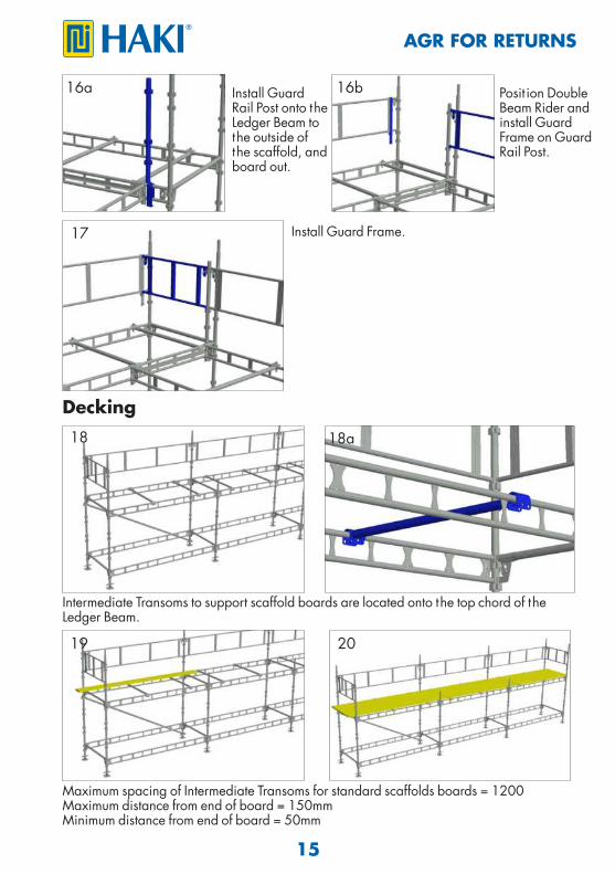
AGR FOR RETURNS
Intermediate Transoms to support scaffold boards are located onto the top chord of the Ledger Beam.
18 18a
Maximum spacing of Intermediate Transoms for standard scaffolds boards = 1200Maximum distance from end of board = 150mmMinimum distance from end of board = 50mm
19 20
Decking
Install Guard Frame.
Install Guard Rail Post onto the Ledger Beam to the outside of the scaffold, and board out.
Posit ion Double Beam Rider and install Guard Frame on Guard Rail Post.
16a 16b
17
16
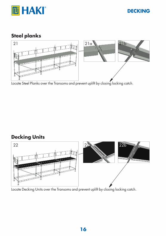
DECKING
Steel planks
Locate Steel Planks over the Transoms and prevent uplift by closing locking catch.
21
22 22a 22b
Locate Decking Units over the Transoms and prevent uplift by closing locking catch.
Decking Units
21a 21b
17
ACCESS AND EGRESS
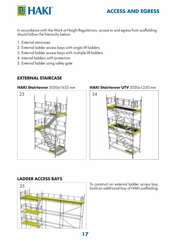
In accordance with the Work at Height Regulat ions, access to and egress from scaffolding should follow the hierarchy below:
1. External staircases2. External ladder access bays with single lift ladders3. External ladder access bays with mult iple lift ladders4. Internal ladders with protect ion5. External ladder using safety gate
EXTERNAL STAIRCASE
HAKI Stairtower 3050x1655 mm HAKI Stairtower UTV 3050x1250 mm
LADDER ACCESS BAYSTo construct an external ladder access bay, build an addit ional bay of HAKI scaffolding.
23 24
25
18
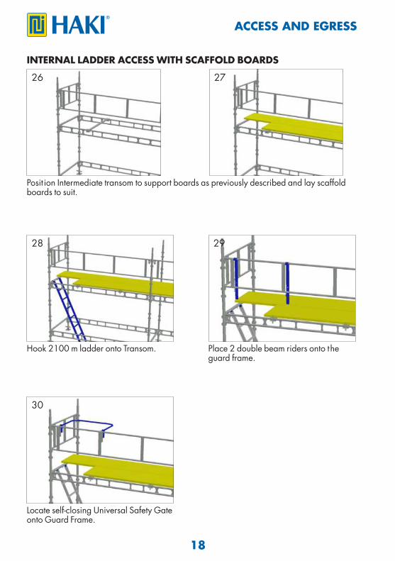
INTERNAL LADDER ACCESS WITH SCAFFOLD BOARDS
Posit ion Intermediate transom to support boards as previously described and lay scaffold boards to suit.
Hook 2100 m ladder onto Transom. Place 2 double beam riders onto the guard frame.
26 27
28 29
ACCESS AND EGRESS
30
Locate self-closing Universal Safety Gate onto Guard Frame.
19
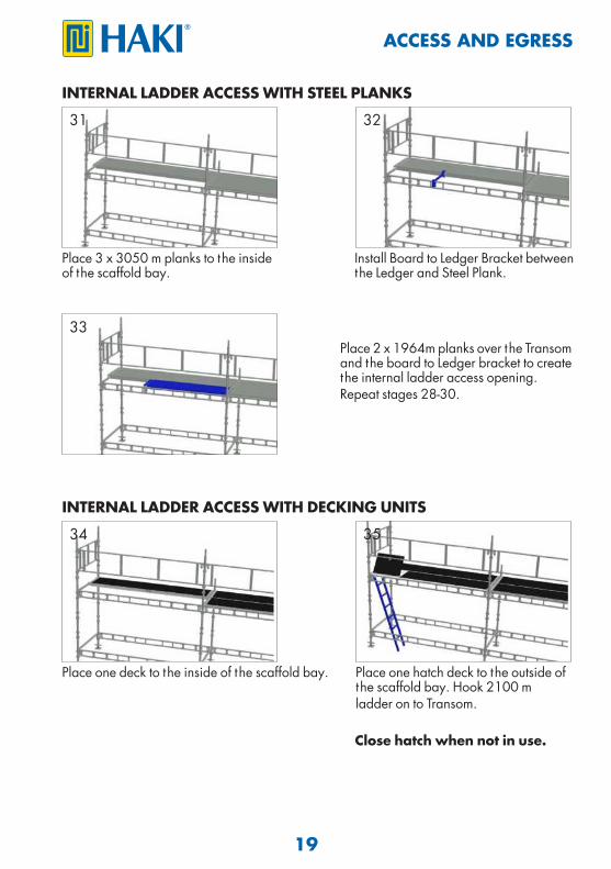
INTERNAL LADDER ACCESS WITH DECKING UNITS
INTERNAL LADDER ACCESS WITH STEEL PLANKS
Close hatch when not in use.
Place one deck to the inside of the scaffold bay.
Place 3 x 3050 m planks to the inside of the scaffold bay.
Place 2 x 1964m planks over the Transom and the board to Ledger bracket to create the internal ladder access opening.Repeat stages 28-30.
31 32
34 35
33
ACCESS AND EGRESS
Install Board to Ledger Bracket between the Ledger and Steel Plank.
Place one hatch deck to the outside of the scaffold bay. Hook 2100 m ladder on to Transom.
20
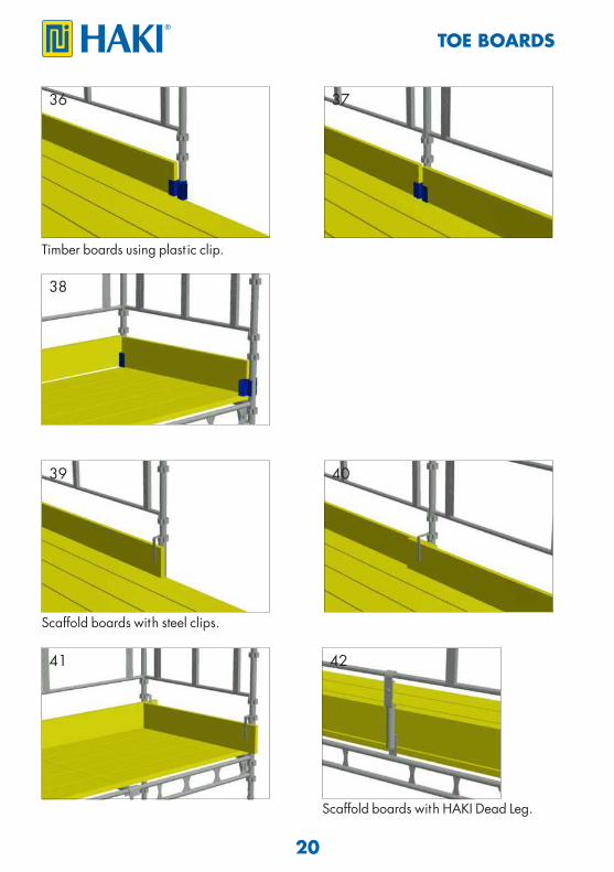
TOE BOARDS
Timber boards using plast ic clip.
36
38
37
39
41
40
Scaffold boards with steel clips.
42
Scaffold boards with HAKI Dead Leg.
21
ALTERNATIVE
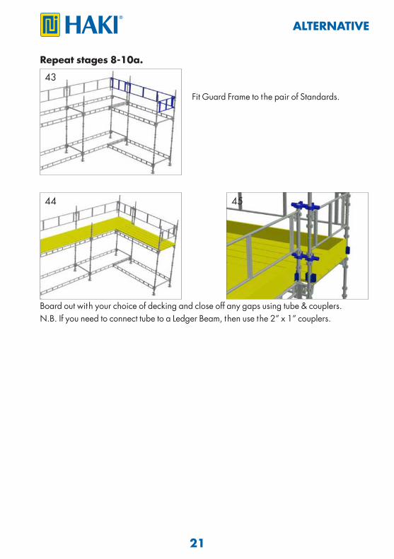
Repeat stages 8-10a.
Board out with your choice of decking and close off any gaps using tube & couplers.N.B. If you need to connect tube to a Ledger Beam, then use the 2” x 1” couplers.
Fit Guard Frame to the pair of Standards.
43
44 45
22
BRACKETS
STAGE BRACKETS FOR SCAFFOLD BOARDS
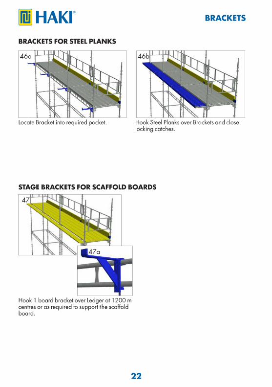
Hook 1 board bracket over Ledger at 1200 m centres or as required to support the scaffold board.
Locate Bracket into required pocket. Hook Steel Planks over Brackets and close locking catches.
BRACKETS FOR STEEL PLANKS
47
47a
46a 46b
23
2-3 BOARD ADJUSTABLE BRACKETS
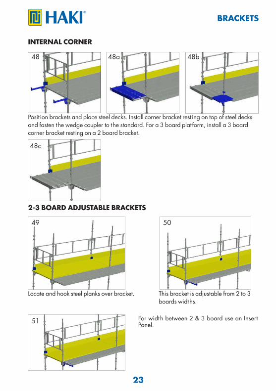
Locate and hook steel planks over bracket.
For width between 2 & 3 board use an Insert Panel.
Posit ion brackets and place steel decks. Install corner bracket rest ing on top of steel decks and fasten the wedge coupler to the standard. For a 3 board platform, install a 3 board corner bracket rest ing on a 2 board bracket.
INTERNAL CORNER
49 50
48 48a 48b
51
This bracket is adjustable from 2 to 3 boards widths.
BRACKETS
48c
24
BRACKETS WITH GUARD FRAMES
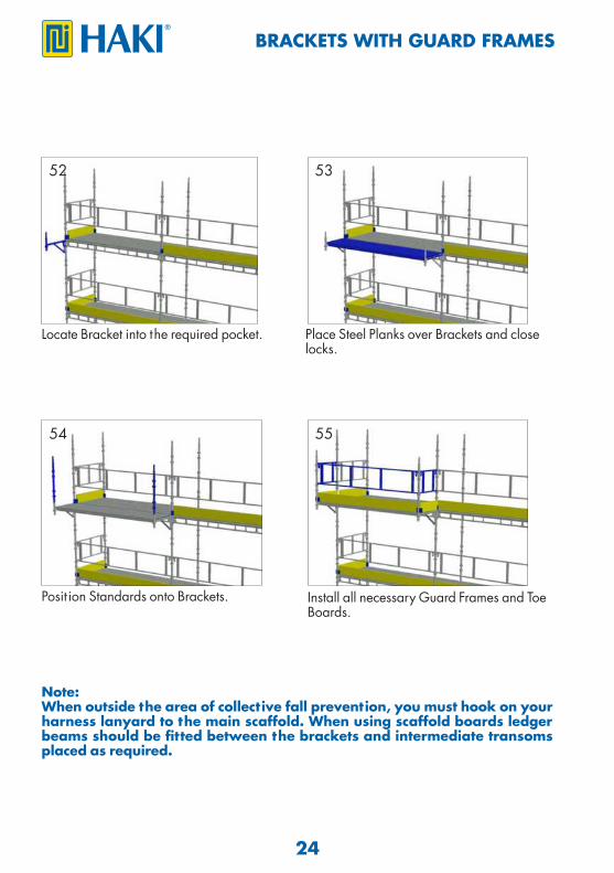
Note:When outside the area of collective fall prevention, you must hook on your harness lanyard to the main scaffold. When using scaffold boards ledger beams should be fitted between the brackets and intermediate transoms placed as required.
Posit ion Standards onto Brackets.
Locate Bracket into the required pocket. Place Steel Planks over Brackets and close locks.
52 53
Install all necessary Guard Frames and Toe Boards.
54 55
25
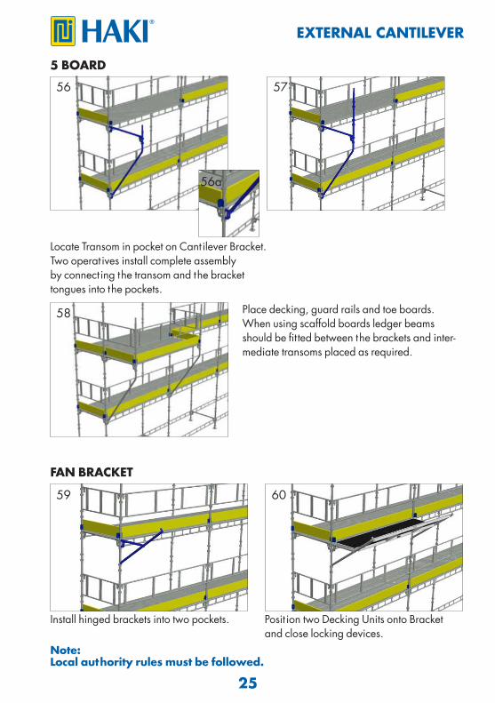
5 BOARD
FAN BRACKET
Install hinged brackets into two pockets. Posit ion two Decking Units onto Bracket and close locking devices.
Place decking, guard rails and toe boards. When using scaffold boards ledger beams should be fitted between the brackets and inter-mediate transoms placed as required.
Locate Transom in pocket on Cantilever Bracket. Two operat ives install complete assembly by connect ing the transom and the bracket tongues into the pockets.
56 57
58
59 60
EXTERNAL CANTILEVER
56a
Note:Local authority rules must be followed.
26
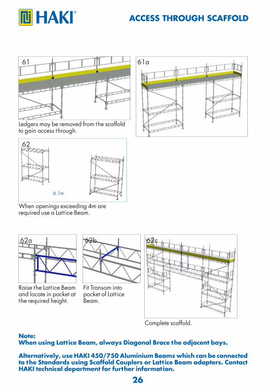
ACCESS THROUGH SCAFFOLD
Ledgers may be removed from the scaffold to gain access through.
When openings exceeding 4m are required use a Latt ice Beam.
61
62
Note:When using Lattice Beam, always Diagonal Brace the adjacent bays.
Alternatively, use HAKI 450/750 Aluminium Beams which can be connected to the Standards using Scaffold Couplers or Lattice Beam adapters. Contact HAKI technical department for further information.
Raise the Latt ice Beam and locate in pocket at the required height.
Complete scaffold.
Fit Transom into pocket of Latt ice Beam.
62a 62c62b
6.1m
61a
27
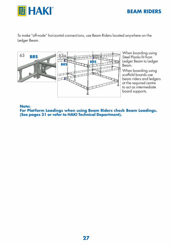
BEAM RIDERS
When boarding using Steel Planks fit from Ledger Beam to Ledger Beam.When boarding using scaffold boards use beam riders and ledgers at the required centre to act as intermediate board supports.
To make “off-node” horizontal connect ions, use Beam Riders located anywhere on theLedger Beam.
Note:For Platform Loadings when using Beam Riders check Beam Loadings. (See pages 31 or refer to HAKI Technical Department).
63 63aBRSBRS
BRS
28
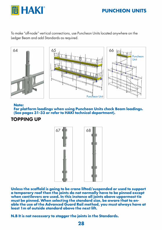
PUNCHEON UNITS
To make “off-node” vert ical connect ions, use Puncheon Units located anywhere on theLedger Beam and add Standards as required.
64 65
Note:For platform loadings when using Puncheon Units check Beam loadings. (See pages 31-33 or refer to HAKI technical department).
Puncheon Unit
Puncheon Unit
66
Unless the scaffold is going to be crane lifted/suspended or used to support a temporary roof then the joints do not normally have to be pinned except when cantilevers are used. In this instance all joints above uppermost tie must be pinned. When selecting the standard size, be aware that to en-able the use of the Advanced Guard Rail method, you must always have at least 1m of outside standard above the next lift.
N.B It is not necessary to stagger the joints in the Standards.
67 68
TOPPING UP
29
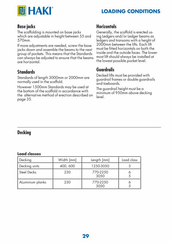
Base jacksThe scaffolding is mounted on base jacks which are adjustable in height between 55 and 570mm.If more adjustments are needed, screw the base jacks down and assemble the beams to the next group of pockets. This means that the Standards can always be adjusted to ensure that the beams are horizontal. Standards Standards of length 3000mm or 2000mm are normally used in the scaffold.However 1500mm Standards may be used at the bottom of the scaffold in accordance with the alternat ive method of erect ion described on page 35.
Horizontals Generally, the scaffold is erected us-ing Ledgers and/or Ledger beams as ledgers and transoms with a height of 2000mm between the lifts. Each lift must be fitted horizontals on both the inside and the outside faces. The lower-most lift should always be installed at the lowest possible pocket level.
GuardrailsDecked lifts must be provided with guardrail frames or double guardrails and toeboards.The guardrail height must be aminimum of 950mm above decking level.
Decking
Decking Width [mm] Length [mm] Load class
Decking units 400, 600 1250-3050 3
Steel Decks 230 770-22503050
65
ALuminium planks 230 770-22503050
65
Load classes
LOADING CONDITIONS
30
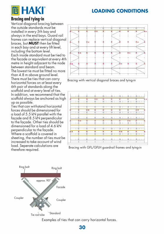
Bracing and tying-inVert ical diagonal bracing between the outside standards must be installed in every 5th bay and always in the end bays. Guard rail frames can replace vert ical diagonal braces, but MUST then be fitted in each bay and at every lift level, including the bottom level.Each inside standard must be t ied to the facade or equivalent at every 4th metre in height adjacent to the node between standard and beam.The lowest t ie must be fitted no more than 4.8 m above ground level.There must be t ies that can carry horizontal forces on at least every 6th pair of standards along the scaffold and at every level of t ies.In addit ion, we recommend that the scaffold always be anchored as high up as possible.Ties that can withstand horizontal forces should be dimensioned for a load of 5.5 kN parallel with the façade and 8.5 kN perpendicular to the façade. Other t ies should be dimensioned for a load of 4.6 kN perpendicular to the façade.Where a scaffold is covered insheet ing, the number of t ies must beincreased to take account of windload. Seperate calculat ions are therefore required.
Bracing with vert ical diagonal braces and tying-in
Bracing with GFL/GFLH guardrail frames and tying-in
Ring bolt
Standard
Facade
Ring bolt
Tie rod tube
approx. 90°
CouplerCoupler
Examples of t ies that can carry horizontal forces.
LOADING CONDITIONS
31
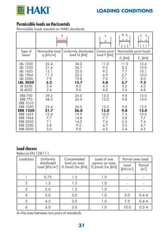
Permissible loads on HorizontalsPermissible loads erected on HAKI standards.
LOADING CONDITIONS
Type of beam
Permissible loadq [kN/m]
Uniformly distributed load Q [kN]
Centre point load P [kN]
Permissible point loads
P3 [kN] P4 [kN]
LBL 1050LBL 1250LBL 1655LBL 1964LBL 2500LBL 3050LB 3650LB 4050
32.421.415.111.37.95.22.42.4
34.026.725.022.219.815.78.69.6
11.09.59.26.97.05.84.34.8
11.08.57.76.77.15.73.23.6
12.410.010.110.08.07.24.34.8
ERB 700ERB 770ERB 1010ERB 1050ERB 1250ERB 1655ERB 1964ERB 2050ERB 2500ERB 3050
39.338.5
25.421.712.47.77.13.83.0
26.026.0
26.026.019.914.814.29.39.0
13.013.0
13.013.010.07.77.44.74.5
9.89.8
9.89.87.55.85.53.53.4
13.013.0
13.013.010.07.77.44.74.5
Load classes Refers to EN 12811-1.
Loadclass Uniformly distributed
load [kN/m2]
Concentrated load on area
0.5mx0.5m [kN]
Load of one person on area
0.2mx0.2m [kN]
Part ial area load
Load [kN/m2]
Part ial [m2]
1 0.75 1.5 1.0 - -
2 1.5 1.5 1.0 - -
3 2.0 1.5 1.0 - -
4 3.0 3.0 1.0 5.0 0.4 A
5 4.5 3.0 1.0 7.5 0.4 A
6 6.0 3.0 1.0 10.0 0.5 AA=the area between two pairs of standards
32
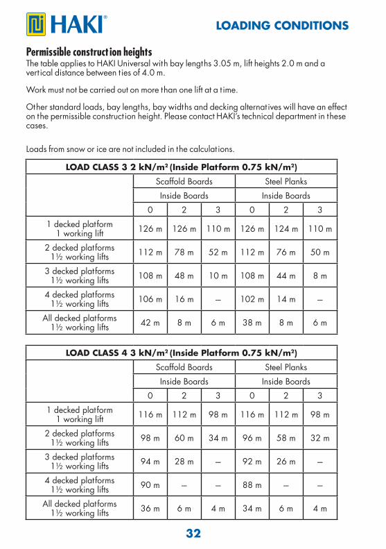
Permissible construct ion heightsThe table applies to HAKI Universal with bay lengths 3.05 m, lift heights 2.0 m and a vert ical distance between t ies of 4.0 m.
Work must not be carried out on more than one lift at a t ime.
Other standard loads, bay lengths, bay widths and decking alternat ives will have an effect on the permissible construct ion height. Please contact HAKI’s technical department in these cases.
Loads from snow or ice are not included in the calculat ions.
LOAD CLASS 3 2 kN/m2 (Inside Platform 0.75 kN/m2)Scaffold Boards Steel Planks
Inside Boards Inside Boards
0 2 3 0 2 3
1 decked platform1 working lift 126 m 126 m 110 m 126 m 124 m 110 m
2 decked platforms1½ working lifts 112 m 78 m 52 m 112 m 76 m 50 m
3 decked platforms1½ working lifts 108 m 48 m 10 m 108 m 44 m 8 m
4 decked platforms1½ working lifts 106 m 16 m --- 102 m 14 m ---
All decked platforms1½ working lifts 42 m 8 m 6 m 38 m 8 m 6 m
LOADING CONDITIONS
LOAD CLASS 4 3 kN/m2 (Inside Platform 0.75 kN/m2)Scaffold Boards Steel Planks
Inside Boards Inside Boards
0 2 3 0 2 3
1 decked platform1 working lift 116 m 112 m 98 m 116 m 112 m 98 m
2 decked platforms1½ working lifts 98 m 60 m 34 m 96 m 58 m 32 m
3 decked platforms1½ working lifts 94 m 28 m --- 92 m 26 m ---
4 decked platforms1½ working lifts 90 m --- --- 88 m --- ---
All decked platforms1½ working lifts 36 m 6 m 4 m 34 m 6 m 4 m
33
LOADING CONDITION
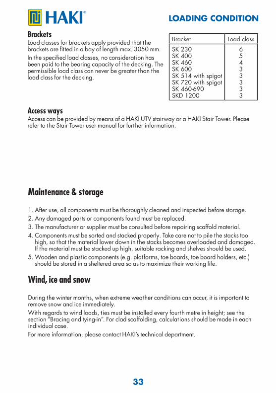
BracketsLoad classes for brackets apply provided that the brackets are fitted in a bay of length max. 3050 mm.In the specified load classes, no considerat ion has been paid to the bearing capacity of the decking. The permissible load class can never be greater than the load class for the decking.
Bracket Load class
SK 230SK 400SK 460SK 600SK 514 with spigotSK 720 with spigotSK 460-690SKD 1200
65433333
Access waysAccess can be provided by means of a HAKI UTV stairway or a HAKI Stair Tower. Please refer to the Stair Tower user manual for further information.
Maintenance & storage
1. After use, all components must be thoroughly cleaned and inspected before storage.2. Any damaged parts or components found must be replaced.3. The manufacturer or supplier must be consulted before repairing scaffold material.4. Components must be sorted and stacked properly. Take care not to pile the stacks too high, so that the material lower down in the stacks becomes overloaded and damaged. If the material must be stacked up high, suitable racking and shelves should be used.5. Wooden and plast ic components (e.g. plat forms, toe boards, toe board holders, etc.) should be stored in a sheltered area so as to maximize their working life.
Wind, ice and snow
During the winter months, when extreme weather condit ions can occur, it is important to remove snow and ice immediately.With regards to wind loads, t ies must be installed every fourth metre in height; see the sect ion “Bracing and tying-in”. For clad scaffolding, calculat ions should be made in each individual case.For more information, please contact HAKI’s technical department.
34
LOADING CONDITION
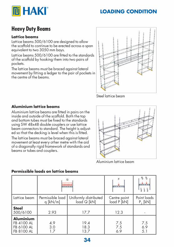
Lattice beamsLatt ice beams 500/6100 are designed to allow the scaffold to cont inue to be erected across a span equivalent to two 3050 mm bays.Latt ice beams 500/6100 are fitted to the standards of the scaffold by hooking them into two pairs of pockets.The latt ice beams must be braced against lateral movement by fitt ing a ledger to the pair of pockets in the centre of the beams.
Permissible loads on lattice beams
Heavy Duty Beams
Aluminium lattice beamsAluminium latt ice beams are fitted in pairs on the inside and outside of the scaffold. Both the top and bottom tubes must be fixed to the standards using SW 48x48 double couplers or use latt ice beam connectors to standard. The height is adjust-ed so that the decking is level when this is fitted.The latt ice beams must be braced against lateral movement at least every other metre with the aid of a diagonally rigid framework of standards and beams or tubes and couplers.
Latt ice beam Permissible load q [kN/m]
Uniformly distributed load Q [kN]
Centre point load P [kN]
Point loads P3 [kN]
Steel500/6100 2.93 17.7 12.3 -
AluminiumFB 4100 ALFB 6100 ALFB 8100 AL
4.93.01.7
19.418.313.7
7.57.56.9
7.56.95.1
Steel latt ice beam
Aluminium latt ice beam
35
SAFE SCAFFOLDING
Planning to use Advance Guard Rail
3.0
m
1.5 m
2.0
m2.
0 m
2.0 m
2.0 m
2.0
m2.
0 m
2.0
m
1.5
m
2.0 m 2.0
m2.
0 m
2.0 m
2.0 m
1.5
m2.
0 m
2.0
m
3.0
m
1.5 m
2.0
m2.
0 m
2.0 m
2.0 m
3.0
m3.
0 m
2.0
m
2.0
m
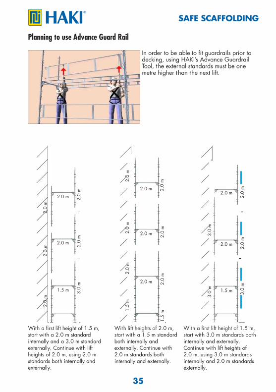
With a first lift height of 1.5 m, start with a 2.0 m standardinternally and a 3.0 m standard externally. Continue with lift heights of 2.0 m, using 2.0 m standards both internally and externally.
With lift heights of 2.0 m, start with a 1.5 m standard both internally and externally. Continue with 2.0 m standards both internally and externally.
With a first lift height of 1.5 m, start with 3.0 m standards both internally and externally.Continue with lift heights of 2.0 m, using 3.0 m standards internally and 2.0 m standards externally.
In order to be able to fit guardrails prior to decking, using HAKI’s Advance Guardrail Tool, the external standards must be one metre higher than the next lift.
36
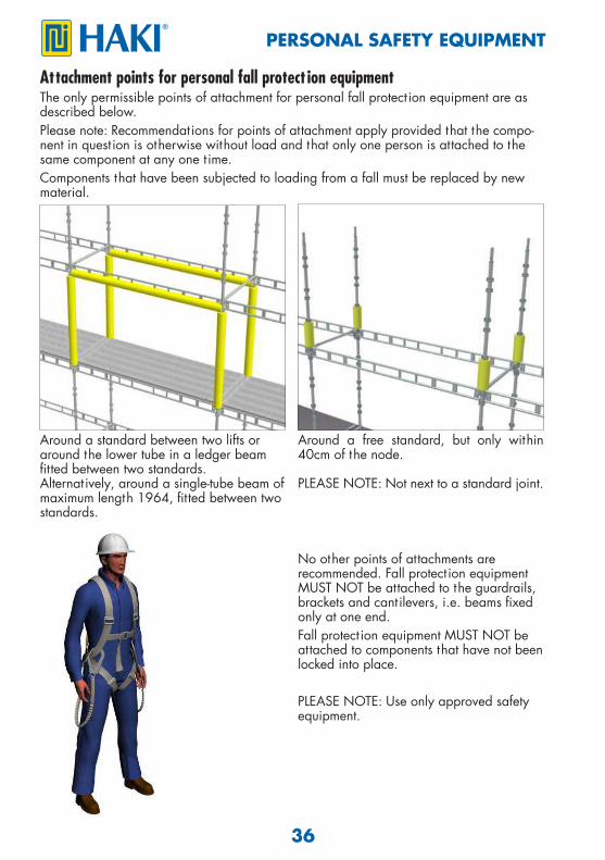
Attachment points for personal fall protect ion equipmentThe only permissible points of attachment for personal fall protect ion equipment are as described below. Please note: Recommendations for points of attachment apply provided that the compo-nent in quest ion is otherwise without load and that only one person is attached to the same component at any one t ime.Components that have been subjected to loading from a fall must be replaced by new material.
Around a standard between two lifts oraround the lower tube in a ledger beam fi tted between two standards.Alternat ively, around a single-tube beam ofmaximum length 1964, fi tted between two standards.
Around a free standard, but only within 40cm of the node.
PLEASE NOTE: Not next to a standard joint.
No other points of attachments are recommended. Fall protect ion equipment MUST NOT be attached to the guardrails, brackets and cantilevers, i.e. beams fi xed only at one end. Fall protect ion equipment MUST NOT be attached to components that have not been locked into place.
PLEASE NOTE: Use only approved safety equipment.
PERSONAL SAFETY EQUIPMENT
37
Notes
SPECIALISTS IN SCAFFOLDING AND WEATHER PROTECTION SYSTEMS
Experience With over 50 years experience to call on, HAKI has gained a leading reputat ion in its field. With its own R & D and manufacturing facilit ies, the company now operates throughout Europe and its equipment is in use worldwide. With all products designed and manufactured to ISO 9001:2008, and a comprehensive training and support infrastructure, you can rely on HAKI for support.
Training The Company´s dedicated Training Centre is equipped with the full range of HAKI products where a comprehensive choice of courses is offered. With the benefit of this training, all users of HAKI products can be assured that the equipment is being employed safely and effect ively.
Support From computerised est imat ing facilit ies to on site assessment and project back up, HAKI is with its customers every step of the way. Working with HAKI means far more than just proven equipment, it means working with People who understand the scaffolding industry. Whatever the project, the company is committed to ensuring every user enjoys the full benefits associated with the use of HAKI - maximising the savings, profitably, and above all, SAFETY.
© H
AKI
AB
2015
03
P00
0175
Pr
int A
M-Tr
yck
Häs
sleho
lm 2
015
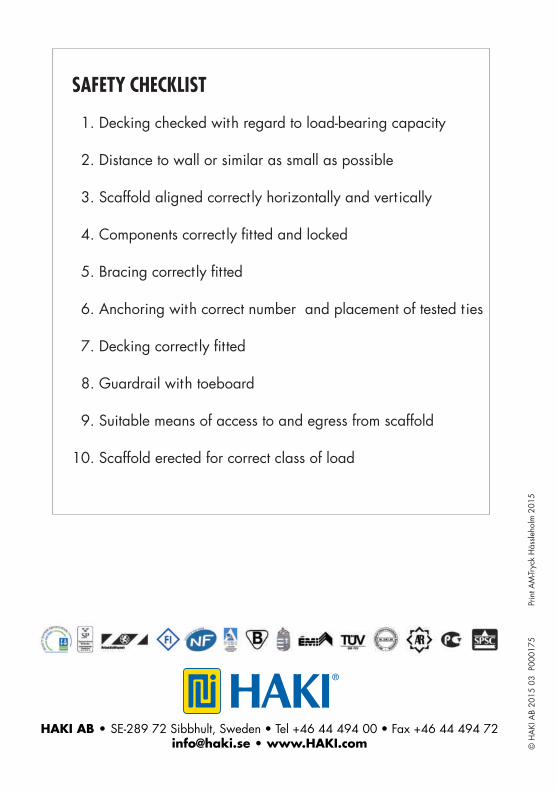
SAFETY CHECKLIST
1. Decking checked with regard to load-bearing capacity
2. Distance to wall or similar as small as possible
3. Scaffold aligned correct ly horizontally and vert ically 4. Components correct ly fi tted and locked
5. Bracing correct ly fi tted
6. Anchoring with correct number and placement of tested t ies
7. Decking correct ly fi tted
8. Guardrail with toeboard
9. Suitable means of access to and egress from scaffold
10. Scaffold erected for correct class of load
HAKI AB • SE-289 72 Sibbhult, Sweden • Tel +46 44 494 00 • Fax +46 44 494 72 [email protected] • www.HAKI.com