Embed Size (px)
Citation preview
Interrupts, Low Power Modes and Timer A
(Chapters 6 & 8)

Status RegisterRegisters

Interrupts(Chapter 6 in text)
A computer has 2 basic ways to react to inputs:1) polling: The processor regularly looks at the input and
reacts as appropriate.+ easy to implement and debug- processor intensive
• if event is rare, you waste a lot of time checking• processor can’t go into low power (slow or stopped) modes
2) interrupts: The processor is “interrupted” by an event.+ very efficient time-wise: no time wasted looking for an event
that hasn’t occurred.+ very efficient energy-wise: processor can be asleep most of the
time.- can be hard to debug
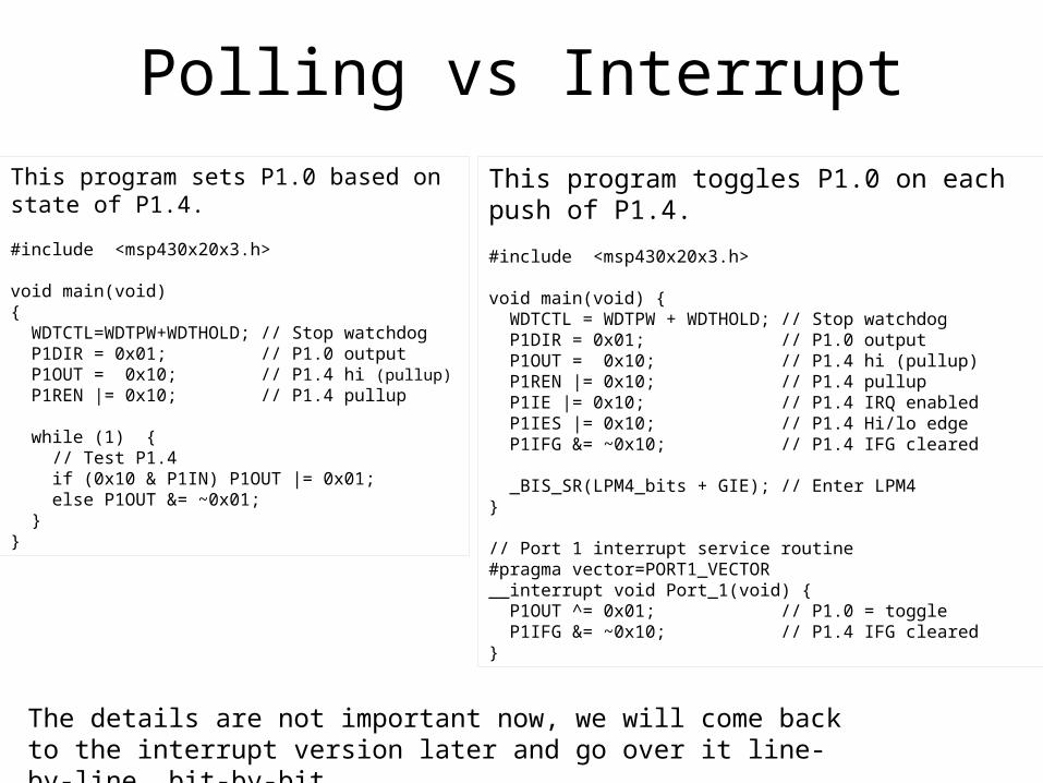
Polling vs InterruptThis program toggles P1.0 on each push of P1.4.
#include <msp430x20x3.h>
void main(void) { WDTCTL = WDTPW + WDTHOLD; // Stop watchdog P1DIR = 0x01; // P1.0 output P1OUT = 0x10; // P1.4 hi (pullup) P1REN |= 0x10; // P1.4 pullup P1IE |= 0x10; // P1.4 IRQ enabled P1IES |= 0x10; // P1.4 Hi/lo edge P1IFG &= ~0x10; // P1.4 IFG cleared
_BIS_SR(LPM4_bits + GIE); // Enter LPM4}
// Port 1 interrupt service routine#pragma vector=PORT1_VECTOR__interrupt void Port_1(void) { P1OUT ^= 0x01; // P1.0 = toggle P1IFG &= ~0x10; // P1.4 IFG cleared}
This program sets P1.0 based on state of P1.4.
#include <msp430x20x3.h>
void main(void){ WDTCTL=WDTPW+WDTHOLD; // Stop watchdog P1DIR = 0x01; // P1.0 output P1OUT = 0x10; // P1.4 hi (pullup) P1REN |= 0x10; // P1.4 pullup
while (1) { // Test P1.4 if (0x10 & P1IN) P1OUT |= 0x01; else P1OUT &= ~0x01; }}
The details are not important now, we will come back to the interrupt version later and go over it line-by-line, bit-by-bit.
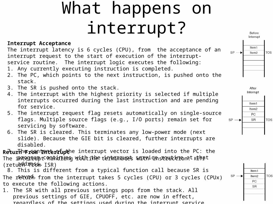
What happens on interrupt?Interrupt AcceptanceThe interrupt latency is 6 cycles (CPU), from the acceptance of an interrupt request to the start of execution of the interrupt-service routine. The interrupt logic executes the following:1. Any currently executing instruction is completed.2. The PC, which points to the next instruction, is pushed onto the stack.3. The SR is pushed onto the stack.4. The interrupt with the highest priority is selected if multiple interrupts occurred during the last
instruction and are pending for service.5. The interrupt request flag resets automatically on single-source flags. Multiple source flags
(e.g., I/O ports) remain set for servicing by software.6. The SR is cleared. This terminates any low-power mode (next slide). Because the GIE bit is
cleared, further interrupts are disabled.7. The content of the interrupt vector is loaded into the PC: the program continues with the
interrupt service routine at that address.8. This is different from a typical function call because SR is saved.
Return From InterruptThe interrupt handling routine terminates with instruction: RETI (return from ISR)
The return from the interrupt takes 5 cycles (CPU) or 3 cycles (CPUx) to execute the following actions.1. The SR with all previous settings pops from the stack. All previous settings of GIE, CPUOFF, etc.
are now in effect, regardless of the settings used during the interrupt service routine.2. The PC pops from the stack and begins execution at the point where it was interrupted.

Low power modes
AA battery has capacity of about 2 Amp-hours.
This is about 2 million hours (228 years) at 0.1 μA.

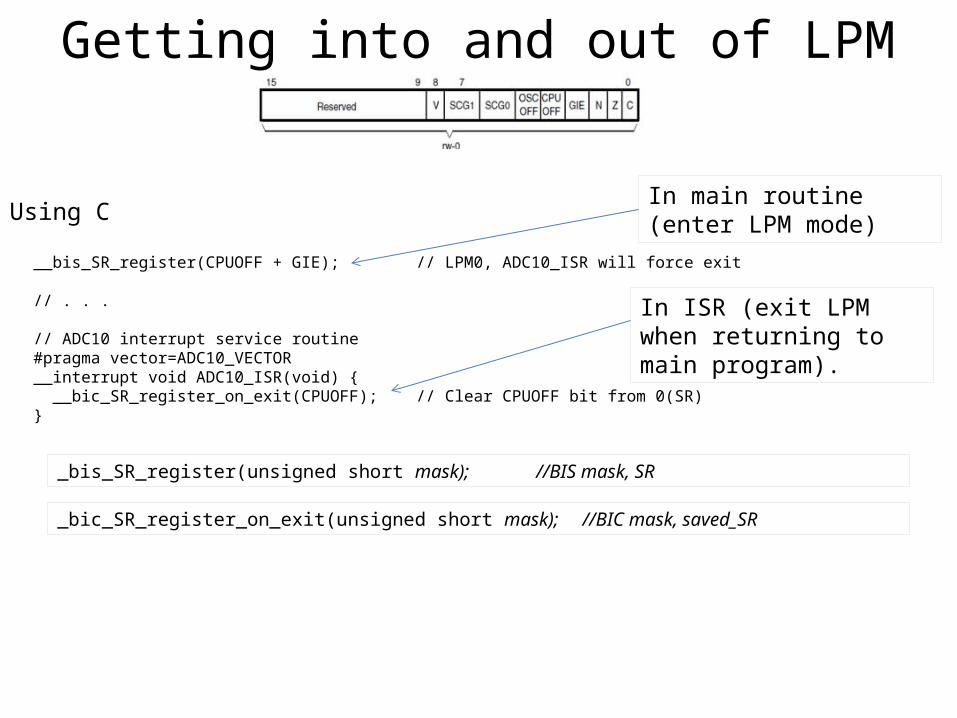
Getting into and out of LPM
Getting into and out of LPM
Using C
__bis_SR_register(CPUOFF + GIE); // LPM0, ADC10_ISR will force exit
// . . .
// ADC10 interrupt service routine#pragma vector=ADC10_VECTOR__interrupt void ADC10_ISR(void) { __bic_SR_register_on_exit(CPUOFF); // Clear CPUOFF bit from 0(SR)}
In main routine (enter LPM mode)
In ISR (exit LPM when returning to main program).
_bis_SR_register(unsigned short mask); //BIS mask, SR
_bic_SR_register_on_exit(unsigned short mask); //BIC mask, saved_SR

Registers that effect interrupts on P1
If interrupt enable bit is set in (P1IE), and Global Interrupts are enabled (GIE in Status Register), an interrupt is requested when the corresponding interrupt flag is set (P1IFG).
If a bit in PIES=0, the corresponding bit in P1IFG is set on rising edge on corresponding input pin (P1IN).
If PIES=1, P1IFG is set on falling edge of P1IN.

Using interrupts on Port 1Toggles P1.0 on each push of P1.4.
void main(void) { WDTCTL = WDTPW + WDTHOLD; // Stop watchdog P1DIR = 0x01; // P1.0 output P1OUT = 0x10; // P1.4 hi (pullup) P1REN |= 0x10; // P1.4 pullup P1IE |= 0x10; // P1.4 IRQ enabled P1IES |= 0x10; // P1.4 Hi/lo edge P1IFG &= ~0x10; // P1.4 IFG cleared
_BIS_SR(LPM4_bits + GIE); // Enter LPM4}
// Port 1 interrupt service routine#pragma vector=PORT1_VECTOR__interrupt void Port_1(void) { P1OUT ^= 0x01; // P1.0 = toggle P1IFG &= ~0x10; // P1.4 IFG cleared}
P1.0 is output
P1.4 resistor is enabled
P1.4 resistor is connected to logic 1
Enable interrupt on P1.4 (GIE is still cleared)
Set sensitivity to falling edge.
Clear Interrupt flag (just in case).
Enter LPM4 and enable interrupts
Tell compiler to fill in interrupt vector with address of this function
Tell compiler to return from function with “iret” (as opposed to “ret”)
Toggle P1.0
Clear interrupt flag. (Some interrupts do this automatically, check manual, or example code)
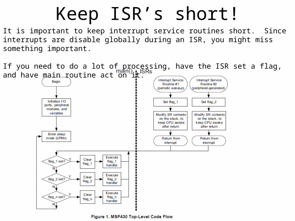
Keep ISR’s short!It is important to keep interrupt service routines short. Since interrupts are disable globally during an ISR, you might miss something important.
If you need to do a lot of processing, have the ISR set a flag, and have main routine act on it.

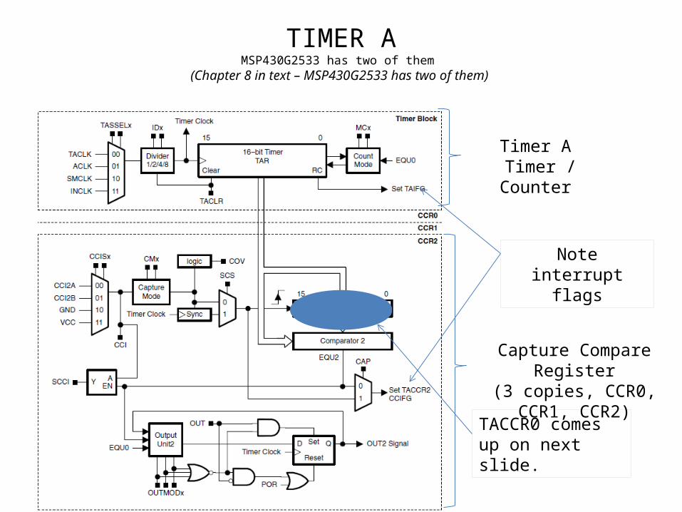
TIMER AMSP430G2533 has two of them
(Chapter 8 in text – MSP430G2533 has two of them)
Timer A Timer / Counter
Capture Compare Register(3 copies, CCR0, CCR1, CCR2)
Note interrupt flags
TACCR0 comes up on next slide.

Timer / Counter
• The timer register (TAR) can be read and written and can generate an interrupt on overflow.It can be cleared with TACLR.
• TASSELA selects on of four inputs• IDA chooses one of four divider• MCA chooses one of four counting modes
See previous page for definition

TIMER A Registers
If we wanted to use TAIFG for a periodic interrupt, the ISR would have to set the value of TAR to 0xffff-(desired delay count – 1).
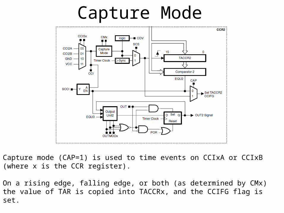
Capture Mode
Capture mode (CAP=1) is used to time events on CCIxA or CCIxB (where x is the CCR register). On a rising edge, falling edge, or both (as determined by CMx) the value of TAR is copied into TACCRx, and the CCIFG flag is set.
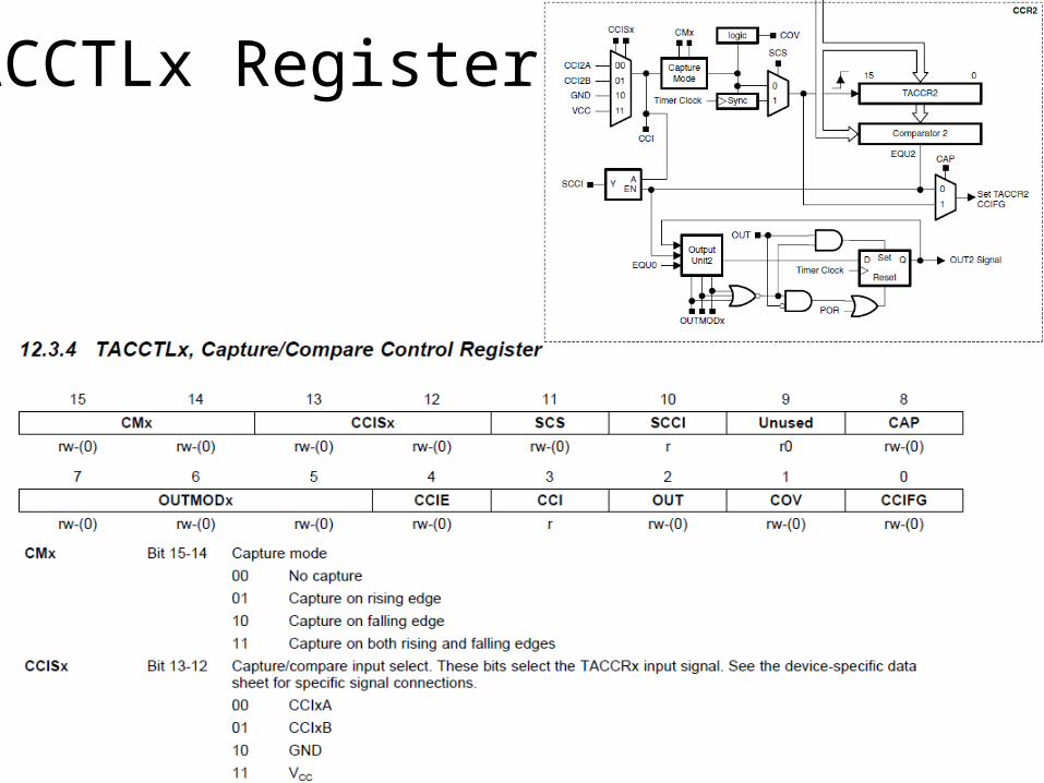
TACCTLx Register
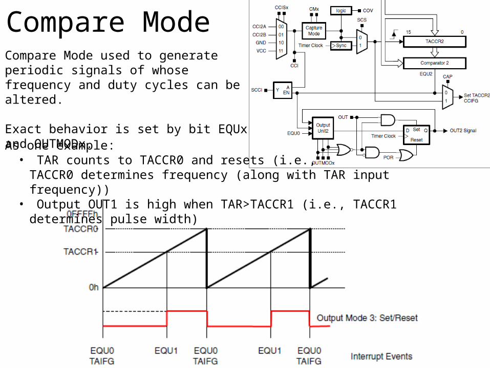
Compare ModeCompare Mode used to generate periodic signals of whose frequency and duty cycles can be altered.
Exact behavior is set by bit EQUx and OUTMODx.
As one example:• TAR counts to TACCR0 and resets (i.e.,
TACCR0 determines frequency (along with TAR input frequency))• Output OUT1 is high when TAR>TACCR1 (i.e., TACCR1 determines pulse width)
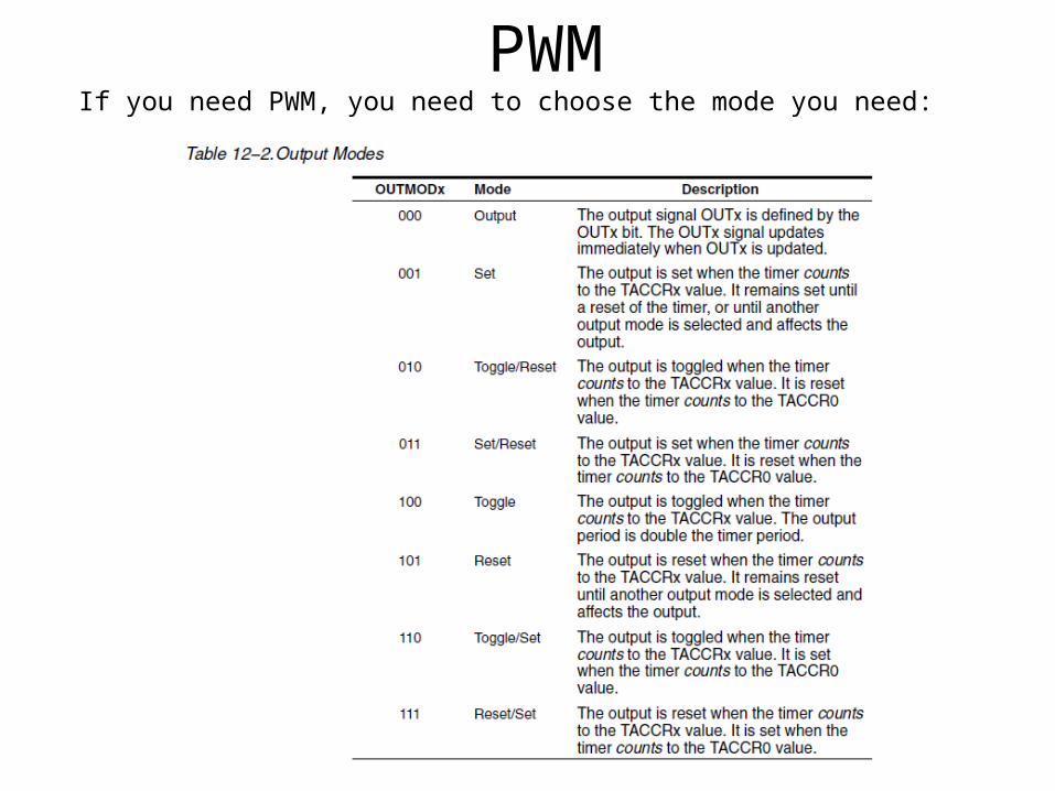
PWMIf you need PWM, you need to choose the mode you need:

PWM modes
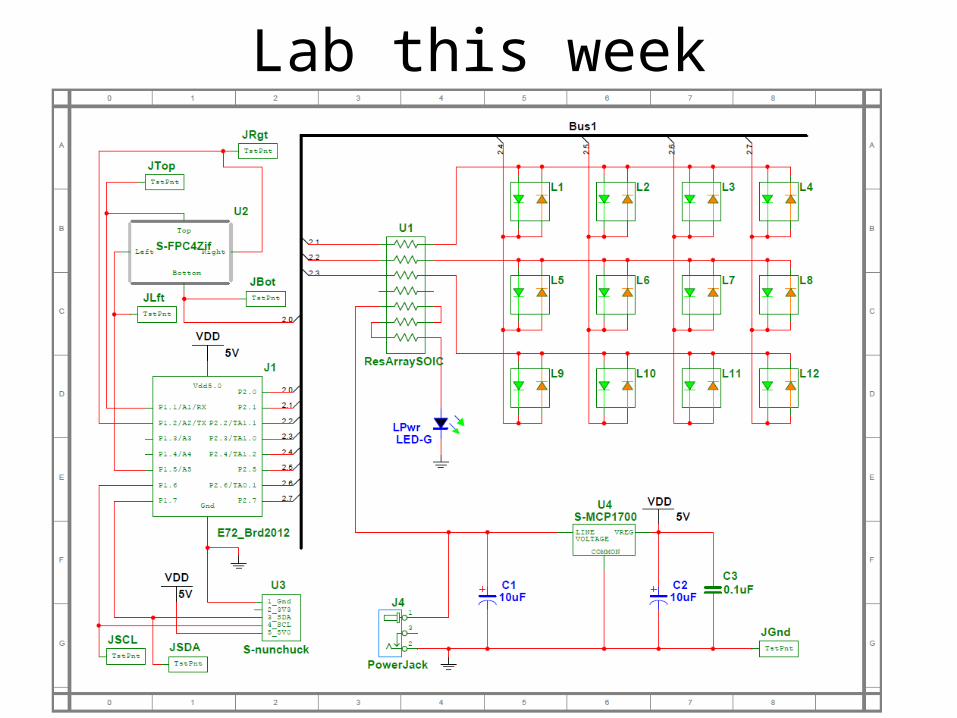
Lab this week


![1. General description - NXP SemiconductorsCT32B1_MAT[3:0] CT32B1_CAP[1:0](2) DCD, DSR(1), RI(1) 16-bit COUNTER/TIMER 1 WINDOWED WATCHDOG TIMER GPIO GROUP0 INTERRUPTS CT16B1_MAT[1:0]](https://img.pdfslide.net/doc/110x75/60e24064d4feac73b520d504/1-general-description-nxp-semiconductors-ct32b1mat30-ct32b1cap102-dcd.jpg)