Embed Size (px)
Citation preview
Intersection of Convex Objects: The Method ofSeparating Axes
David EberlyGeometric Tools, LLChttp://www.geometrictools.com/Copyright c© 1998-2012. All Rights Reserved.
Created: January 28, 2001Last Modified: March 2, 2008
Contents
1 Introduction 2
2 Separation by Projection onto a Line 2
3 Separation of Convex Polygons in 2D 2
4 Separation of Convex Polyhedra in 3D 5
5 Separation of Convex Polygons in 3D 6
6 Separation of Moving Convex Objects 7
7 Contact Set for Moving Convex Objects 9
8 Example: Two Moving Triangles in 2D 10
9 Example: Two Moving Triangles in 3D 15
1
1 Introduction
This document describes the method of separating axes, a method for determining whether or not twostationary convex objects are intersecting. The ideas can be extended to handle moving convex objects andare useful for predicting collisions of the objects and for computing the first time of contact. The currentfocus of this document is on the test intersection geometric query, a query that just indicates whether ornot an intersection exists or will occur when the objects are moving. The problem of computing the set ofintersection is denoted a find intersections geometric query and is generally more difficult to implement thanthe test intersection query. Information from the test query can help determine the contact set that the findquery must construct. This document will describe in what way the test query information can be used.
2 Separation by Projection onto a Line
A test for nonintersection of two convex objects is simply stated: If there exists a line for which the intervalsof projection of the two objects onto that line do not intersect, then the objects are do not intersect. Sucha line is called a separating line or, more commonly, a separating axis. The translation of a separating lineis also a separating line, so it is sufficient to consider lines that contain the origin. Given a line containingthe origin and with unit-length direction D, the projection of a compact1, convex2 set C onto the line is theinterval
I = [λmin(D), λmax(D)] = [min{D ·X : X ∈ C},max{D ·X : X ∈ C}].
Two compact convex sets C0 and C1 are separated if there exists a direction D such that the projectionintervals I0 and I1 do not intersect. Specifically they do not intersect when
λ(0)min(D) > λ(1)
max(D) or λ(0)max(D) < λ
(1)min(D). (1)
The superscript corresponds to the index of the convex set. Although the comparisons are made where Dis unit length, the comparison results are invariant to changes in length of the vector. This follows fromλmin(tD) = tλmin(D) and λmax(tD) = tλmax(D) for t > 0. The Boolean value of the pair of comparisons isalso invariant when D is replaced by the opposite direction −D. This follows from λmin(−D) = −λmax(D)and λmax(−D) = −λmin(D). When D is not unit length, the intervals obtained for the separating axis testsare not the projections of the object onto the line, rather they are scaled versions of the projection intervals.I make no distinction in this document between the scaled projection and regular projection. I will also usethe terminology that the direction vector for a separating axis is called a separating direction, a directionthat is not necessarily unit length.
3 Separation of Convex Polygons in 2D
For a pair of convex polygons in 2D, only a finite set of direction vectors needs to be considered for separationtests. That set includes the normal vectors to the edges of the polygons. The left picture in Figure 3.1 shows
1 A set is compact if it is closed and bounded. To illustrate in one dimension, the interval [0, 1] is closed and bounded, so itis compact. The interval [0, 1) is bounded, but not closed since it does not contain the limiting point 1, so it is not compact.The interval [0,∞) is closed, but not bounded, so it is not compact.
2 A set is convex if given any two points P and Q in the set, the line segment (1− t)P+ tQ for t ∈ [0, 1] is also in the set.In one dimension, both [0, 1] and [0, 1) are convex.
2
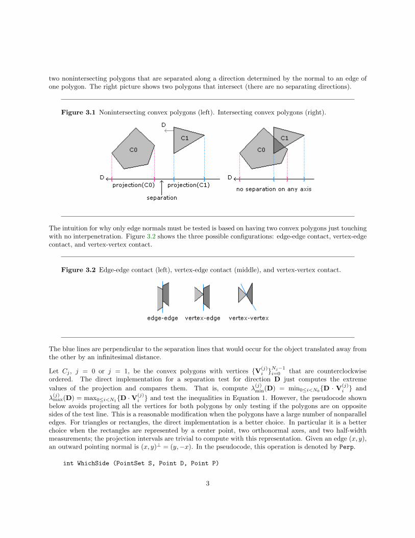
two nonintersecting polygons that are separated along a direction determined by the normal to an edge ofone polygon. The right picture shows two polygons that intersect (there are no separating directions).
Figure 3.1 Nonintersecting convex polygons (left). Intersecting convex polygons (right).
The intuition for why only edge normals must be tested is based on having two convex polygons just touchingwith no interpenetration. Figure 3.2 shows the three possible configurations: edge-edge contact, vertex-edgecontact, and vertex-vertex contact.
Figure 3.2 Edge-edge contact (left), vertex-edge contact (middle), and vertex-vertex contact.
The blue lines are perpendicular to the separation lines that would occur for the object translated away fromthe other by an infinitesimal distance.
Let Cj , j = 0 or j = 1, be the convex polygons with vertices {V(j)i }
Nj−1i=0 that are counterclockwise
ordered. The direct implementation for a separation test for direction D just computes the extreme
values of the projection and compares them. That is, compute λ(j)min(D) = min0≤i<N0{D · V
(j)i } and
λ(j)max(D) = max0≤i<N1
{D ·V(j)i } and test the inequalities in Equation 1. However, the pseudocode shown
below avoids projecting all the vertices for both polygons by only testing if the polygons are on oppositesides of the test line. This is a reasonable modification when the polygons have a large number of nonparalleledges. For triangles or rectangles, the direct implementation is a better choice. In particular it is a betterchoice when the rectangles are represented by a center point, two orthonormal axes, and two half-widthmeasurements; the projection intervals are trivial to compute with this representation. Given an edge (x, y),an outward pointing normal is (x, y)⊥ = (y,−x). In the pseudocode, this operation is denoted by Perp.
int WhichSide (PointSet S, Point D, Point P)
3
{
// S vertices are projected to the form P+t*D. Return value is +1 if all t > 0,
// -1 if all t < 0, 0 otherwise, in which case the line splits the polygon.
positive = 0; negative = 0;
for (i = 0; i < C.N; i++)
{
t = Dot(D,S.V(i)-P);
if ( t > 0 ) positive++; else if ( t < 0 ) negative++;
if ( positive && negative ) return 0;
}
return ( positive ? +1 : -1 );
}
bool TestIntersection2D (ConvexPolygon C0, ConvexPolygon C1)
{
// Test edges of C0 for separation. Because of the counterclockwise ordering,
// the projection interval for C0 is [m,0] where m <= 0. Only try to determine
// if C1 is on the ‘positive’ side of the line.
for (i0 = 0, i1 = C0.N-1; i0 < C0.N; i1 = i0, i0++)
{
D = Perp(C0.V(i0) - C0.V(i1));
if ( WhichSide(C1.V,D,C0.V(i0)) > 0 )
{ // C1 is entirely on ‘positive’ side of line C0.V(i0)+t*D
return false;
}
}
// Test edges of C1 for separation. Because of the counterclockwise ordering,
// the projection interval for C1 is [m,0] where m <= 0. Only try to determine
// if C0 is on the ‘positive’ side of the line.
for (i0 = 0, i1 = C1.N-1; i0 < C1.N; i1 = i0, i0++)
{
D = Perp(C1.V(i0) - C1.V(i1));
if ( WhichSide(C0.V,D,C1.V(i0)) > 0 )
{ // C0 is entirely on ‘positive’ side of line C1.V(i0)+t*D
return false;
}
}
return true;
}
4
4 Separation of Convex Polyhedra in 3D
For a pair of convex polyhedra in 3D, only a finite set of direction vectors needs to be considered for separationtests. That set includes the normal vectors to the faces of the polyhedra and vectors generated by a crossproduct of two edges, one from each polyhedron. The intuition is similar to that of convex polygons in 2D. Ifthe two polyhedra are just touching with no interpenetration, then the contact is one of face-face, face-edge,face-vertex, edge-edge, edge-vertex, or vertex-vertex.
Let Cj , j = 0 or j = 1, be the convex polyhedra with vertices {V(j)i }
Nj−1i=0 , edges {E(j)
i }Mj−1i=0 , and faces
{F(j)i }
Lj−1i=0 . Let the faces be planar convex polygons whose vertices are counterclockwise ordered as you
view the face from outside the polyhedron. Outward pointing normal vectors can be stored with each faceas a way of storing the orientation. The pseudocode for 3D that is similar to that in 2D is shown below. Itis assumed that: (1) each face has queries that allow access to the face normal and to a vertex on the faceand (2) each edge has a query that allows access to a vertex on the edge.
bool TestIntersection3D (ConvexPolyhedron C0, ConvexPolyhedron C1)
{
// Test faces of C0 for separation. Because of the counterclockwise ordering,
// the projection interval for C0 is [m,0] where m <= 0. Only try to determine
// if C1 is on the ‘positive’ side of the line.
for (i = 0; i < C0.L; i++)
{
D = C0.F(i).normal; // outward pointing
if ( WhichSide(C1.V,D,C0.F(i).vertex) > 0 )
{ // C1 is entirely on ‘positive’ side of line C0.F(i).vertex+t*D
return false;
}
}
// Test faces of C1 for separation. Because of the counterclockwise ordering,
// the projection interval for C1 is [m,0] where m <= 0. Only try to determine
// if C0 is on the ‘positive’ side of the line.
for (i = 0; i < C1.L; i++)
{
D = C1.F(i).normal; // outward pointing
if ( WhichSide(C0.V,D,C1.F(i).vertex) > 0 )
{ // C0 is entirely on ‘positive’ side of line C1.F(i).vertex+t*D
return false;
}
}
// Test cross product of pairs of edges, one from each polyhedron.
for (i = 0; i < C0.M; i++)
{
for (j = 0; j < C1.M; j++)
{
D = Cross(C0.E(i),C1.E(j));
5
int side0 = WhichSide(C0.V,D,C0.E(i).vertex);
if ( side0 == 0)
{
continue;
}
int side1 = WhichSide(C1.V,D,C0.E(i).vertex);
if ( side1 == 0 )
{
continue;
}
if ( side0*side1 < 0 )
{ // C0 and C1 are on ‘opposite’ sides of line C0.E(i).vertex+t*D
return false;
}
}
}
return true;
}
The WhichSide function is the same as the one for two dimensions, except that the input is now threedimensional.
5 Separation of Convex Polygons in 3D
For a pair of convex polygons in 3D, again only a finite set of direction vectors needs to be considered for
separation tests. Let Cj , j = 0 or j = 1 be the convex polygons with vertices {V(j)i }
Mj−1i=0 with the convention
that V(j)Mj
= V(j)0 . Each set of vertices is necessarily coplanar. Let N(j) be normal vectors for those planes.
The edges for the polygons are E(j)i = V
(j)i+1 −V
(j)i of 0 ≤ i < Mj .
The polygons normals are potential separating directions. If either normal direction separates the polygons,then no intersection occurs. However, if neither normal direction separates the polygons, then two possibil-ities exist for the remaining potential separating directions. The first case is that the polygons are coplanar(the 2D case) and the remaining potential separating directions are those vectors in the common plane and
perpendicular to the triangle edges, N(j) ×E(j)i for 0 ≤ j ≤ 1 and 0 ≤ i < Mj , a total of 2Mj vectors. The
second case is that the polygon planes are not parallel and that each polygon is split by the plane of the other
polygon. The remaining potential separating directions are the cross products E(0)i × E
(1)j for 0 ≤ i < M0
and 0 ≤ j < M1, a total of M0M1 vectors.
The pseudocode for intersection testing is
bool TestIntersection3D (ConvexPolygon C0, ConvexPolygon C1)
{
// test normal for C0
6
if ( WhichSide(C1,C0.N,C0.V(0)) != 0 )
{ // C1 is entirely on one side of plane of C0
return false;
}
}
6 Separation of Moving Convex Objects
The method of separating axes can be extended to handle convex objects moving with constant velocity. IfC0 and C1 are convex objects with velocities W0 and W1, then it can be determined via projections if theobjects will intersect for some time T ≥ 0. Moreover, if they do, the first time of contact can be computed.Without loss of generality, it is enough to work with a stationary object C0 and a moving object C1 withvelocity W since one can always use W = W1 −W0 to perform the calculations as if C0 were not moving.
If the C0 and C1 are initially intersecting, then the first time of contact is T = 0. Otherwise the convexobjects are initially disjoint. The projection of C1 onto a line with direction D not perpendicular to W isitself moving. The speed of the projection along the line is ω = (W ·D)/|D|2. If the projection interval ofC1 moves away from the projection interval of C0, then the two objects will never intersect. The interestingcases are when the projection intervals for C1 move towards those of C0.
The intuition for how to predict an intersection is much like that for selecting the potential separatingdirections in the first place. If the two convex objects intersect at a first time Tfirst > 0, then their projectionsare not separated along any line. An instant before first contact, the objects are separated. Consequentlythere must be at least one separating direction for the objects for Tfirst − ε for small ε > 0. Similarly, if thetwo convex objects intersect at a last time Tlast > 0, then their projections are also not separated at thattime along any line, but an instant after last contact, the objects are separated. Consequently there mustbe at least one separating direction for the objects for Tlast + ε for small ε > 0. Both Tfirst and Tlast canbe tracked as each potential separating axis is processed. After all directions are processed, if Tfirst ≤ Tlast,then the two objects do intersect with first contact time Tfirst. It is also possible that Tfirst > Tlast in whichcase the two objects cannot intersect.
Let S0 and S1 denote the set of potential separating directions and let W0 and W1 denote the velocitiesfor C0 and C1, respectively. Pseudocode for testing for intersection of two moving convex objects is givenbelow. The time interval over which the event is of interest is [0, Tmax]. If knowing an intersection at anyfuture time is desired, then set Tmax = ∞. Otherwise, Tmax is finite. The function possibly can indicatethere is no intersection on [0, Tmax], even though there could be an intersection at some time T > Tmax.
bool ObjectsIntersect (Convex C0, Convex C1, float TMax, float& TFirst, float& TLast)
{
W = C1.W - C0.W; // process as if C0 is stationary, C1 is moving
S = Union(C0.S,C1.S); // all potential separating axes
TFirst = 0; TLast = INFINITY;
for each D in S do
{
speed = Dot(D,W);
min0 = minimum(Dot(D,C0.V(i))); max0 = maximum(Dot(D,C0.V(i)));
min1 = minimum(Dot(D,C1.V(i))); max1 = maximum(Dot(D,C1.V(i)));
7
if ( max1 < min0 ) // interval(C1) initially on ‘left’ of interval(C0)
{
if ( speed <= 0 ) return false; // intervals moving apart
T = (min0 - max1)/speed; if ( T > TFirst ) TFirst = T;
if ( TFirst > TMax ) return false; // ‘quick out’
T = (max0 - min1)/speed; if ( T < TLast ) TLast = T;
if ( TFirst > TLast ) return false; // ‘quick out’
}
else if ( max0 < min1 ) // interval(C1) initially on ‘right’ of interval(C0)
{
if ( speed >= 0 ) return false; // intervals moving apart
T = (max0 - min1)/speed; if ( T > TFirst ) TFirst = T;
if ( TFirst > TMax ) return false; // ‘quick out’
T = (min0 - max1)/speed; if ( T < TLast ) TLast = T;
if ( TFirst > TLast ) return false; // ‘quick out’
}
else // interval(C0) and interval(C1) overlap
{
if ( speed > 0 )
{
T = (max0 - min1)/speed; if ( T < TLast ) TLast = T;
if ( TFirst > TLast ) return false; // ‘quick out’
}
else if ( speed < 0 )
{
T = (min0 - max1)/speed; if ( T < TLast ) TLast = T;
if ( TFirst > TLast ) return false; // ‘quick out’
}
}
}
return true;
}
The following example illustrates the ideas. The first box is the unit cube 0 ≤ x ≤ 1 and 0 ≤ y ≤ 1 and isstationary. The second box is initially 0 ≤ x ≤ 1 and 1 + δ ≤ y ≤ 2 + δ for some δ > 0. Let its velocitybe (1,−1). Whether or not the second box intersects the first box depends on the value of δ. The onlypotential separating axes are (1, 0) and (0, 1). Figure 6.1 shows the initial configuration for three values of δ,one where there will be an edge-edge intersection, one where there will be a vertex-vertex intersection, andone where there is no intersection.
8
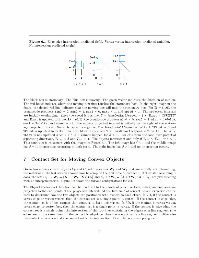
Figure 6.1 Edge-edge intersection predicted (left). Vertex-vertex intersection predicted (middle).No intersection predicted (right).
The black box is stationary. The blue box is moving. The green vector indicates the direction of motion.The red boxes indicate where the moving box first touches the stationary box. In the right image in thefigure, the dotted red line indicates that the moving box will miss the stationary box. For D = (1, 0), thepseudocode produces min0 = 0, max0 = 1, min1 = 0, max1 = 1, and speed = 1. The projected intervalsare initially overlapping. Since the speed is positive, T = (max0-min1)/speed = 1 < TLast = INFINITY
and TLast is updated to 1. For D = (0, 1), the pseudocode produces min0 = 0, max0 = 1, min1 = 1+delta,max1 = 2+delta, and speed = -1. The moving projected interval is initially on the right of the station-ary projected interval. Since the speed is negative, T = (max0-min1)/speed = delta > TFirst = 0 andTFirst is updated to delta. The next block of code sets T = (min0-max1)/speed = 2+delta. The valueTLast is not updated since 2 + δ < 1 cannot happen for δ > 0. On exit from the loop over potentialseparating directions, TFirst = δ and Tlast = 1. The objects intersect if and only if Tfirst ≤ Tlast, or δ ≤ 1.This condition is consistent with the images in Figure 6.1. The left image has δ < 1 and the middle imagehas δ = 1, intersections occurring in both cases. The right image has δ > 1 and no intersection occurs.
7 Contact Set for Moving Convex Objects
Given two moving convex objects C0 and C1 with velocities W0 and W1 that are initially not intersecting,the material in the last section showed how to compute the first time of contact T , if it exists. Assuming itdoes, the sets C0 + TW0 = {X+ TW0 : X ∈ C0} and C1 + TW1 = {X+ TW1 : X ∈ C1} are just touchingwith no interpenetration. Figure 3.2 shows the various configurations for 2D.
The ObjectsIntersect function can be modified to keep track of which vertices, edges, and/or faces areprojected to the end points of the projection interval. At the first time of contact, this information can beused to determine how the two objects are positioned with respect to each other. In 2D, if the contact isvertex-edge or vertex-vertex, then the contact set is a single point, a vertex. If the contact is edge-edge,the contact set is a line segment that contains at least one vertex. In 3D, if the contact is vertex-vertex,vertex-edge, or vertex-face, then the contact set is a single point, a vertex. If the contact is edge-edge, thecontact set is a single point (the intersection of the two lines containing the edges) or a line segment (theedges are on the same line). If the contact is edge-face, then the contact set is a line segment. Otherwisethe contact is face-face and the contact set is the intersection of two planar convex polygons.
9
8 Example: Two Moving Triangles in 2D
Consider two triangles, 〈U0,U1,U2〉 and 〈V0,V1,V2〉, both having counterclockwise ordering. For the sakeof indexing notation, define U3 = U0 and V3 = V0. The edges are Ei = Ui+1−Ui and Fi = Vi+1−Vi for0 ≤ i ≤ 2. Define (x, y)⊥ = (y,−x). Outward pointing normals to the edges are Ni = E⊥i and Mi = F⊥i for0 ≤ i ≤ 2. The six normals are the potential separating directions. Let the triangle velocities be W0 andW1.
In the pseudocode for testing for intersection of two moving convex objects (in this case C0 and C1 representthe two triangles), the calculation of the minimum and maximum projections for the triangles can be doneso that additional information is known about how the two triangles are oriented with respect to each other.Three cases occur for the projection:
1. Two vertices project to the minimum of the interval and one vertex projects to the maximum.
2. One vertex projects to the minimum of the interval and two vertices project to the maximum.
3. One vertex projects to the minimum, one vertex projects to the maximum, and one vertex projects toan interval interior point.
A flag can be associated with each triangle to indicate which of these three cases has occured for a givenpotential separating direction D, call the flag values M21, M12, and M11. In addition the a flag and to theextreme values of the projection, it is necessary to remember the indices of the vertices that map to theextreme values. A convenient data structure is
ProjectionMap { M21, M12, M11 };
Configuration
{
ProjectionMap map;
int index[3];
float min, max;
};
In the function ObjectsIntersect from the last section, two configuration objects are declared, Cfg0 forthe U triangle (the C0 polygon) and Cfg1 for the V triangle (the C1 polygon). To illustrate for the specificcase D = N0, the block
min0 = minimum(Dot(D,U(i)));
max0 = maximum(Dot(D,U(i)));
min1 = minimum(Dot(D,V(i)));
max1 = maximum(Dot(D,V(i)));
where U(i) denotes Ui and V(i) denotes Vi, is replaced by
// U2 maps to minimum, U0 and U1 map to maximum
Cfg0.map = M12;
Cfg0.index[0] = 2; Cfg0.index[1] = 0; Cfg0.index[2] = 1;
10
Cfg0.min = -Dot(N0,E2);
Cfg0.max = 0;
// Compute min and max of interval for second triangle. Keep track of
// vertices that project to min and max.
d0 = Dot(N0,V0-U0); d1 = Dot(N0,V1-U0); d2 = Dot(N0,V2-U0);
if ( d0 <= d1 )
{
if ( d1 <= d2 ) // d0 <= d1 <= d2
{
if ( d0 != d1 )
Cfg1.map = ( d1 != d2 ? M11 : M12 );
else
Cfg1.map = M21;
Cfg1.index[0] = 0; Cfg1.index[1] = 1; Cfg1.index[2] = 2;
Cfg1.min = d0; Cfg1.max = d2;
}
else if ( d0 <= d2 ) // d0 <= d2 < d1
{
if ( d0 != d2 )
{
Cfg1.map = M11;
Cfg1.index[0] = 0; Cfg1.index[1] = 2; Cfg1.index[2] = 1;
}
else
{
Cfg1.map = M21;
Cfg1.index[0] = 2; Cfg1.index[1] = 0; Cfg1.index[2] = 1;
}
Cfg1.min = d0; Cfg1.max = d1;
}
else // d2 < d0 <= d1
{
Cfg1.map = ( d0 != d1 ? M12 : M11 );
Cfg1.index[0] = 2; Cfg1.index[1] = 0; Cfg1.index[2] = 1;
Cfg1.min = d2; Cfg1.max = d1;
}
}
else
{
if ( d2 <= d1 ) // d2 <= d1 < d0
{
if ( d2 != d1 )
{
Cfg1.map = M11;
Cfg1.index[0] = 2; Cfg1.index[1] = 1; Cfg1.index[2] = 0;
11

}
else
{
Cfg1.map = M21;
Cfg1.index[0] = 1; Cfg1.index[1] = 2; Cfg1.index[2] = 0;
}
Cfg1.min = d2; Cfg1.max = d0;
}
else if ( d2 <= d0 ) // d1 < d2 <= d0
{
Cfg1.map = ( fD2 != fD0 ? M11 : M12 );
Cfg1.index[0] = 1; Cfg1.index[1] = 2; Cfg1.index[2] = 0;
Cfg1.min = fD1; Cfg1.max = fD0;
}
else // d1 < d0 < d2
{
Cfg1.map = M11;
Cfg1.index[0] = 1; Cfg1.index[1] = 0; Cfg1.index[2] = 2;
Cfg1.min = fD1; Cfg1.max = fD2;
}
}
Similar blocks of code can be written for other potential separating directions.
The conditional statements comparing minima and maxima must be modified to keep track of the relativelocation of the moving interval to the stationary one. The input configurations are for the current potentialseparating axis. If this axis direction becomes the new candidate for first time of contact, we need toremember its configurations to be used in the function that computes the contact set. The pseudocodebelow stores the configurations, TCfg0 and TCfg1, that correspond to the first time of contact as it iscurrently known.
// ‘side’ is initialized to NONE outside the loop over directions
if ( Cfg1.max < Cfg0.min ) // V-interval initially on ‘left’ of U-interval
{
if ( speed <= 0 ) // intervals moving apart
return false;
// update first time of contact
T = (Cfg0.min - Cfg1.max)/speed;
if ( T > TFirst )
{
TFirst = T;
side = LEFT;
TCfg0 = Cfg0;
TCfg1 = Cfg1;
}
12
// test for exceedance of time interval
T = (Cfg0.max - Cfg1.min)/speed;
if ( T < TLast )
TLast = T;
// test for separation
if ( TFirst > TLast )
return false;
}
else if ( max0 < min1 ) // V-interval initially on ‘right’ of U-interval
{
if ( speed >= 0 )
return false; // intervals moving apart
// update first time of contact
T = (Cfg0.max - Cfg1.min)/speed;
if ( T > TFirst )
{
TFirst = T;
side = RIGHT;
TCfg0 = Cfg0;
TCfg1 = Cfg1;
}
// test for exceedance of time interval
T = (Cfg0.min - Cfg1.max)/speed;
if ( T < TLast )
TLast = T;
// test for separation
if ( TFirst > TLast )
return false;
}
else // U-interval and V-interval overlap
{
if ( speed > 0 )
{
// update last time
T = (Cfg0.max - Cfg1.min)/speed;
if ( T < TLast )
TLast = T;
// test for separation
if ( TFirst > TLast )
return false;
}
else if ( speed < 0 )
13
{
// update last time
T = (Cfg0.min - Cfg1.max)/speed;
if ( T < TLast )
TLast = T;
// test for separation
if ( TFirst > TLast )
return false;
}
}
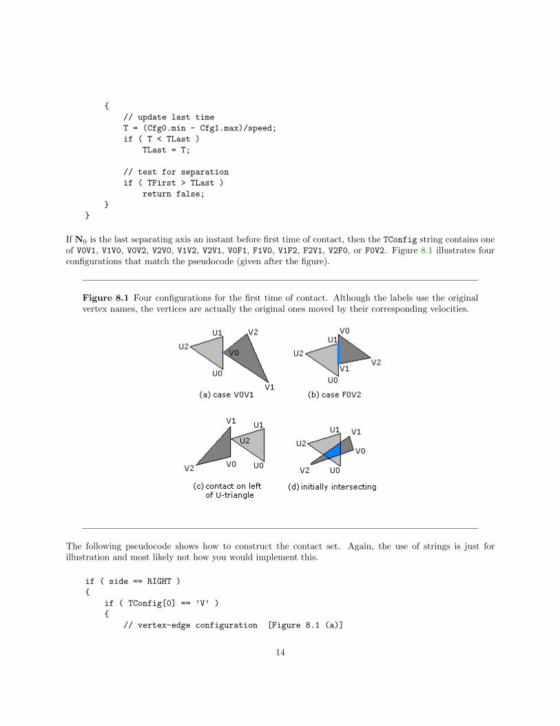
If N0 is the last separating axis an instant before first time of contact, then the TConfig string contains oneof V0V1, V1V0, V0V2, V2V0, V1V2, V2V1, V0F1, F1V0, V1F2, F2V1, V2F0, or F0V2. Figure 8.1 illustrates fourconfigurations that match the pseudocode (given after the figure).
Figure 8.1 Four configurations for the first time of contact. Although the labels use the originalvertex names, the vertices are actually the original ones moved by their corresponding velocities.
The following pseudocode shows how to construct the contact set. Again, the use of strings is just forillustration and most likely not how you would implement this.
if ( side == RIGHT )
{
if ( TConfig[0] == ’V’ )
{
// vertex-edge configuration [Figure 8.1 (a)]
14
contactSet = { Vi + TFirst*W1 }; // i is number in TConfig[1]
}
else // TConfig[0] == ’F’
{
// Edge-edge configuration. See discussion after this code.
// Vi0 is the first vertex and Vi1 is the last vertex of edge Fi
// where i is the number in TConfig[1]. [Figure 8.1 (b)]
min = Dot(E0,Vi1-U0+TFirst*W)/Dot(E0,E0);
max = Dot(E0,Vi0-U0+TFirst*W)/Dot(E0,E0);
I = intersection([0,1],[min,max]); // guaranteed not empty
contactSet = U0 + TFirst*W1 + I*E0; // point or line segment
}
}
else if ( side == LEFT )
{
// vertex-edge configuration [Figure 4 (c)]
contactSet = { U2 + TFirst*W0 };
}
else // triangles were initially intersecting
{
// Intersection set is a convex set: a point, a line segment, or a
// convex polygon with at most six sides. [Figure 8.1 (d)]
Point UMove[3] = { U0+TFirst*W0, U1+TFirst*W0, U2+TFirst*W0 };
Point VMove[3] = { V0+TFirst*W1, V1+TFirst*W1, V2+TFirst*W1 };
contactSet = TriTriIntersection(UMove,VMove);
}
In the case of edge-edge contact, after motion the two triangles touch at either a point or line segment. LetT denote the contact time. For the sake of argument, suppose that the contact edge for the second triangleis F0. The touching edges are parameterized by U0 + TW1 + sE0 for s ∈ [0, 1] and V0 + TW0 + sE0 fors ∈ [µ0, µ1] where
µ0 =(V1 + TW1)− (U0 + TW0)
|E0|2and µ1 =
(V0 + TW1)− (U0 + TW0)
|E0|2.
The overlap of the two edges occurs for s̄ ∈ I = [0, 1]∩ [µ0, µ1] 6= ∅. The corresponding points in the contactset are U0 + TW0 + s̄E0.
In the event the two triangles are initially overlapping, the contact set is more expensive to construct. It canbe a single point, a line segment, or a convex polygon with at most six sides. This set can be constructedby standard methods involving Boolean operations on polygons.
9 Example: Two Moving Triangles in 3D
Consider two triangles, 〈U0,U1,U2〉 and 〈V0,V1,V2〉. For the sake of indexing notation, define U3 = U0
and V3 = V0. The edges are Ei = Ui+1 −Ui and Fi = Vi+1 −Vi for 0 ≤ i ≤ 2. A normal for the firsttriangle is N = E0 × E1 and a normal for the second triangle is M = F0 × F1. If the triangles are not
15
coplanar, then the potential separating directions are N, M, and Ei×Fj for 0 ≤ i ≤ 2 and 0 ≤ j ≤ 2. If thetriangles are parallel, but are not in the same plane, then N is a separating direction and the other directionsneed not be tested. Moreover, if N and M do not separate non-coplanar triangles, then the vectors Ei ×Fj
cannot be zero. If the triangles are coplanar, then the potential separating directions are N×Ei and N×Fi
for 0 ≤ i ≤ 2. This is exactly the 2D situation discussed earlier.
If D is a potential separating direction, then the block for computing the intervals of projection is morecomplex than that of its 2D counterpart. Both triangles are projected onto the separating axis. Eachprojection interval must be sorted to determine the appropriate configuration. The left/right relationshipof the two projection intervals must be determined. The set of configurations for the projection of a singletriangle consists of the following:
• 3: All three vertices project to the same point. This happens when D is a normal vector to one of thetriangles.
• 2-1: Two vertices project to the minimum point of the interval, one vertex projects to the maximumpoint.
• 1-2: One vertex projects to the minimum point of the interval, two vertices project to the maximumpoint.
• 1-1-1: The three vertices project to distinct points in the interval.
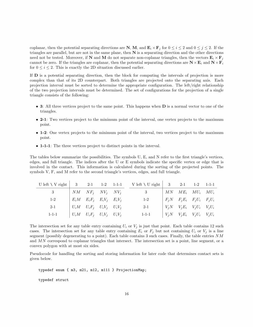
The tables below summarize the possibilities. The symbols U, E, and N refer to the first triangle’s vertices,edges, and full triangle. The indices after the U or E symbols indicate the specific vertex or edge that isinvolved in the contact. This information is calculated during the sorting of the projected points. Thesymbols V, F, and M refer to the second triangle’s vertices, edges, and full triangle.
U left \ V right 3 2-1 1-2 1-1-1
3 NM NFj NVj NVj
1-2 EiM EiFj EiVj EiVj
2-1 UiM UiFj UiVj UiVj
1-1-1 UiM UiFj UiVj UiVj
V left \ U right 3 2-1 1-2 1-1-1
3 MN MEi MUi MUi
1-2 FjN FjEi FjUi FjUi
2-1 VjN VjEi VjUi VjUi
1-1-1 VjN VjEi VjUi VjUi
The intersection set for any table entry containing Ui or Vj is just that point. Each table contains 12 suchcases. The intersection set for any table entry containing Ei or Fj but not containing Ui or Vj is a linesegment (possibly degenerating to a point). Each table contains 3 such cases. Finally, the table entries NMand MN correspond to coplanar triangles that intersect. The intersection set is a point, line segment, or aconvex polygon with at most six sides.
Pseudocode for handling the sorting and storing information for later code that determines contact sets isgiven below.
typedef enum { m3, m21, m12, m111 } ProjectionMap;
typedef struct
16

{
ProjectionMap map; // how vertices map to projection interval
int index[3]; // the sorted indices of the vertices
float min, max; // the interval is [min,max]
}
Config;
Config GetConfiguration (Point D, Point U[3])
{
// D is potential separating direction
// U[3] are the triangle vertices
Configuration config;
d0 = Dot(D,U[0]), d1 = Dot(D,U[1]), d2 = Dot(D,U[2]);
if ( d0 <= d1 )
{
if ( d1 <= d2 ) // d0 <= d1 <= d2
{
config.index[0] = 0; config.index[1] = 1; config.index[2] = 2;
config.min = d0; config.max = d2;
if ( d0 != d1 )
config.map = ( d1 != d2 ? m111 : m12 );
else
config.map = ( d1 != d2 ? m21 : m3 );
}
else if ( d0 <= d2 ) // d0 <= d2 < d1
{
config.index[0] = 0; config.index[1] = 2; config.index[2] = 1;
config.min = d0; config.max = d1;
config.map = ( d0 != d2 ? m111 : m21 );
}
else // d2 < d0 <= d1
{
config.index[0] = 2; config.index[1] = 0; config.index[2] = 1;
config.min = d2; config.max = d1;
config.map = ( d0 != d1 ? m12 : m111 );
}
}
else
{
if ( d2 <= d1 ) // d2 <= d1 < d0
{
config.index[0] = 2; config.index[1] = 1; config.index[2] = 0;
config.min = d2; config.max = d0;
config.map = ( d2 != d1 ? m111 : m21 );
}
else if ( d2 <= d0 ) // d1 < d2 <= d0
{
17
config.index[0] = 1; config.index[1] = 2; config.index[2] = 0;
config.min = d1; config.max = d0;
config.map = ( d2 != d0 ? m111 : m12 );
}
else // d1 < d0 < d2
{
config.index[0] = 1; config.index[1] = 0; config.index[2] = 2;
config.min = d1; config.max = d2;
config.map = m111;
}
}
return config;
}
Pseudocode for determining how the projection intervals relate to each other is given below.
bool Update (Config UC, Config VC, float speed,
Side& side, Config& TUC, Config& TVC, float& TFirst, float& TLast)
{
if ( VC.max < UC.min ) // V-interval initially on ‘left’ of U-interval
{
if ( speed <= 0 ) return false; // intervals moving apart
T = (UC.min - VC.max)/speed;
if ( T > TFirst ) { TFirst = T; side = LEFT; TUC = UC; TVC = VC; }
T = (UC.max - VC.min)/speed; if ( T < TLast ) TLast = T;
if ( TFirst > TLast ) return false;
}
else if ( UC.max < VC.min ) // V-interval initially on ‘right’ of U-interval
{
if ( speed >= 0 ) return false; // intervals moving apart
T = (UC.max - VC.min)/speed;
if ( T > TFirst ) { TFirst = T; side = RIGHT; TUC = UC; TVC = VC; }
T= (UC.min - VC.max)/speed; if ( T < TLast ) TLast = T;
if ( TFirst > TLast ) return false;
}
else // U-interval and V-interval overlap
{
if ( speed > 0 )
{
T = (UC.max - VC.min)/speed;
if ( T < TLast ) TLast = T; if ( TFirst > TLast ) return false;
}
else if ( speed < 0 )
{
T = (UC.min - VC.max)/speed;
if ( T < TLast ) TLast = T; if ( TFirst > TLast ) return false;
}
}
18
return true;
}
It is assumed that the following routines exist for use in contact determination:
• Intersection of two line segments, call it SegSegIntersection.
• Intersection of line segment and triangle that are coplanar, call it SegTriIntersection.
• Intersection of triangle and triangle that are coplanar, call it CoplanarTriTriIntersection.
• Intersection of two stationary triangles, call it TriTriIntersection. This routine will contain a callto the coplanar intersection routine if the triangles happen to be coplanar.
Pseudocode for computing the contact set is given below.
ContactSet GetFirstContact (Point U[3], Point W0, Point V[3], Point W1,
Side side, Config TUC, Config TVC, float TFirst)
{
// move triangles to first contact
Point UTri[3] = { U[0]+TFirst*W0, U[1]+TFirst*W0, U[2]+TFirst*W0 };
Point VTri[3] = { V[0]+TFirst*W1, V[1]+TFirst*W1, V[2]+TFirst*W1 };
Segment USeg, VSeg;
if ( side == RIGHT ) // V-interval on right of U-interval
{
if ( TUC.map == m21 || TUC.map == m111 )
return UTri[TUC.index[2]];
if ( TVC.map == m12 || TVC.map == m111 )
return VTri[TVC.index[0]];
if ( TUC.map == m12 )
{
USeg = <UTri[TUC.index[1]],UTri[TUC.index[2]]>;
if ( TVC.map == m21 )
{
VSeg = <VTri[TVC.index[0]],VTri[TVC.index[1]]>;
return SegSegIntersection(USeg,VSeg);
}
else // TVC.map == m3
{
return SegTriIntersection(USeg,VTri);
}
}
else // TUC.map == m3
{
if ( TVC.map == m21 )
19
{
VSeg = <VTri[TVC.index[0]],VTri[TVC.index[1]]>;
return SegTriIntersection(VSeg,UTri);
}
else // TVC.map == m3
{
return CoplanarTriTriIntersection(UTri,VTri);
}
}
}
else if ( side == LEFT ) // V-interval on left of U-interval
{
if ( TVC.map == m21 || TVC.map == m111 )
return VTri[TVC.index[2]];
if ( TUC.map == m12 || TUC.map == m111 )
return UTri[TUC.index[0]];
if ( TVC.map == m12 )
{
VSeg = <VTri[TVC.index[1]],VTri[TVC.index[2]]>;
if ( TUC.map == m21 )
{
USeg = <UTri[TUC.index[0]],UTri[TUC.index[1]]>;
return SegSegIntersection(USeg,VSeg);
}
else // TUC.map == m3
{
return SegTriIntersection(VSeg,UTri);
}
}
else // TVC.map == m3
{
if ( TUC.map == m21 )
{
USeg = <UTri[TUC.index[0]],UTri[TUC.index[1]]>;
return SegTriIntersection(USeg,VTri);
}
else // TUC.map == m3
{
return CoplanarTriTriIntersection(UTri,VTri);
}
}
}
else // triangles were initially intersecting
{
return TriTriIntersection(UTri,VTri);
}
20
}
The pseudocode that puts all this together is
bool TrianglesIntersect (Point U[3], Point W0, Point V[3], Point W1,
float& TFirst, float& TLast, ContactSet& contact)
{
W = W1 - W0;
S = set of all potential separating axes;
TFirst = 0; TLast = INFINITY;
side = NONE;
Config TUC, TVC;
for each D in S do
{
speed = Dot(D,W);
Config UC = GetConfiguration(D,U);
Config VC = GetConfiguration(D,V);
if ( !Update(UC,VC,speed,side,TUC,TVC,TFirst,TLast) )
return false;
}
contact = GetFirstContact(U,W0,V,W1,side,TUC,TVC,TFirst);
return true;
}
21