Embed Size (px)
Citation preview

Computers and Chemical Engineering 23 (1999) 1527–1543
Interval-based targeting for pollution prevention via massintegration
M. Bahy Noureldin, Mahmoud M. El-Halwagi *Department of Chemical Engineering, Auburn Uni6ersity, Auburn, AL 36849, USA
Accepted 20 September 1999
Abstract
Mass integration is a holistic approach to the optimal allocation, generation, and separation of streams and species. It addressespollution using a combination of strategies including manipulation of process equipment, structural changes in the flowsheet,rerouting of streams and addition of new units. In the past, systematic mass integration techniques were developed to determineoptimal strategies for the recycle and separation of process streams. The purpose of this paper is to introduce two novelcontributions that can greatly expand the scope of mass integration for pollution prevention. First, maximum achievable pollutiontargets will be determined ahead of design and with little input data. In this context, we will illustrate the use of interval arithmeticto determine these targets. Second, pollution prevention through unit manipulation will be addressed. The devised interval-basedtargets posess the attractive feature that they are global regardless of the nonlinearity nature of the process model. These newconcepts are illustrated with a case study. © 1999 Elsevier Science Ltd. All rights reserved.
Keywords: Pollution; Mass integration; Interval; Targeting
www.elsevier.com/locate/compchemeng
root causes of the environmental problems at the heartof the process. In this regard, mass integration providesa unique framework for addressing in-plant pollutionprevention. Mass integration is a holistic approach tothe generation, separation, and routing of species andstreams throughout the process. It is a systematicmethodology that provides a fundamental understand-ing of the global flow of mass within the process andemploys this understanding in identifying performancetargets and optimising the allocation, separation, andgeneration of streams and species. For recent literatureon mass integration, the reader is referred to the text-book by El-Halwagi (1997) and the review article byEl-Halwagi and Spriggs (1998).
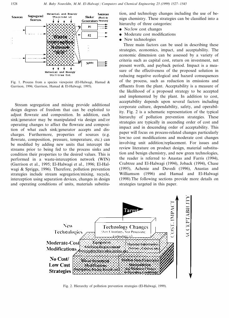
The first step in conducting mass integration analysisis the development of a global mass allocation represen-tation of the whole process from a species viewpoint asshown in Fig. 1. For each targeted species (e.g. eachpollutant), there are sources (streams that carry thespecies) and process sinks (units that can accept thespecies). Process sinks include reactors, heaters/coolers,biotreatment facilities, and discharge media. Streamsleaving the sinks become, in turn, sources. Therefore,sinks are also generators of the targeted species.
1. Introduction
Until recently, environmental solutions to processingfacilities were in the form of end-of-pipe pollutioncontrol strategies. These are peripheral solutions thatfocus primarily on chemical, biological, and physicaltreatment of terminal streams. The result has beenwaste-treatment solutions that reduced the volume andtoxicity of undesirable pollutants in industrial dis-charges. Although these pollution control strategieshave resulted in reducing negative environmental conse-quences of processing facilities, they focused on thesymptoms and not the true causes of the environmentalproblems. Therefore, they lacked cost-effectiveness andsustainability. It has been recently recognised that sus-tainable waste reduction must be based on an insightfulpollution prevention that is founded on thorough un-derstanding of the technical and economic issues of theprocess. This approach enables engineers to address the
* Corresponding author. Tel.: +1-334-844-2064; fax: +1-334-844-2063.
E-mail address: [email protected] (M.M. El-Halwagi)
0098-1354/99/$ - see front matter © 1999 Elsevier Science Ltd. All rights reserved.
PII: S 0 0 9 8 -1354 (99 )00309 -9
M. Bahy Noureldin, M.M. El-Halwagi / Computers and Chemical Engineering 23 (1999) 1527–15431528
Fig. 1. Process from a species viewpoint (El-Halwagi, Hamad &Garrison, 1996; Garrison, Hamad & El-Halwagi, 1995).
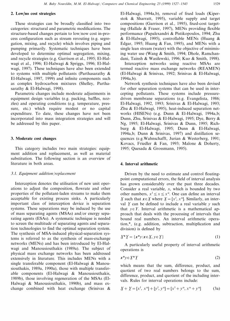
tion, and technology changes including the use of be-nign chemistry. These strategies can be classified into ahierarchy of three categories:� No/low cost changes� Moderate cost modifications� New technologies
Three main factors can be used in describing thesestrategies, economics, impact, and acceptability. Theeconomic dimension can be assessed by a variety ofcriteria such as capital cost, return on investment, netpresent worth, and payback period. Impact is a mea-sure of the effectiveness of the proposed solution inreducing negative ecological and hazard consequencesof the process, such as reduction in emissions andeffluents from the plant. Acceptability is a measure ofthe likelihood of a proposed strategy to be acceptedand implemented by the plant. In addition to cost,acceptability depends upon several factors includingcorporate culture, dependability, safety, and operabil-ity. Fig. 2 is a schematic representation of the typicalhierarchy of pollution prevention strategies. Thesestrategies are typically in ascending order of cost andimpact and in descending order of acceptability. Thispaper will focus on process-related changes particularlylow/no cost modifications and moderate cost changesinvolving unit addition/replacement. For issues andreview literature on product design, material substitu-tion and benign chemistry, and new green technologies,the reader is referred to Anastas and Farris (1994),Crabtree and El-Halwagi (1994), Joback (1994), Chase(1995), Achenie and Duvedi (1996), Anastas andWilliamson (1996) and Hamad and El-Halwagi(1998).The following sections provide more details onstrategies targeted in this paper.
Stream segregation and mixing provide additionaldesign degrees of freedom that can be exploited toadjust flowrate and composition. In addition, eachsink/generator may be manipulated via design and/oroperating changes to affect the flowrate and composi-tion of what each sink/generator accepts and dis-charges. Furthermore, properties of sources (e.g.flowrate, composition, pressure, temperature, etc.) canbe modified by adding new units that intercept thestreams prior to being fed to the process sinks andcondition their properties to the desired values. This isperformed in a waste-interception network (WIN)(Garrison et al., 1995; El-Halwagi et al., 1996; El-Hal-wagi & Spriggs, 1996). Therefore, pollution preventionstrategies include stream segregation/mixing, recycle,interception using separation devices, changes in designand operating conditions of units, materials substitu-
Fig. 2. Hierarchy of pollution prevention strategies (El-Halwagi, 1999).
M. Bahy Noureldin, M.M. El-Halwagi / Computers and Chemical Engineering 23 (1999) 1527–1543 1529
2. Low/no cost strategies
These strategies can be broadly classified into twocategories: structural and parametric modifications. Thestructure-based changes pertain to low/now cost in-pro-cess configuration such as stream rerouting (e.g. segre-gation, mixing, and recycle) which involves piping andpumping primarily. Systematic techniques have beendeveloped to determine optimal segregation, mixing,and recycle strategies (e.g. Garrison et al., 1995; El-Hal-wagi et al., 1996; El-Halwagi & Spriggs, 1996; El-Hal-wagi, 1997). These techniques have also been extendedto systems with multiple pollutants (Parthasarathy &El-Halwagi, 1997, 1999) and infinite components suchas complex hydrocarbon mixtures (Shelley, Partha-sarathy & El-Halwagi, 1998).
Parametric changes include moderate adjustments inequipment design variables (e.g. packing, baffles, noz-zles) and operating conditions (e.g. temperature, pres-sure, etc.) which require modest or no capitalexpenditure. To date, these changes have not beenincorporated into mass integration strategies and willbe addressed by this paper.
3. Moderate cost changes
This category includes two main strategies: equip-ment addition and replacement, as well as materialsubstitution. The following section is an overview ofliterature in both areas.
3.1. Equipment addition/replacement
Interception denotes the utilisation of new unit oper-ations to adjust the composition, flowrate and otherproperties of the pollutant-laden streams to make themacceptable for existing process sinks. A particularlyimportant class of interception device is separationsystems. These separations may be induced by the useof mass separating agents (MSAs) and/or energy sepa-rating agents (ESAs). A systematic technique is neededto screen the multitude of separating agents and separa-tion technologies to find the optimal separation system.The synthesis of MSA-induced physical-separation sys-tems is referred to as the synthesis of mass-exchangenetworks (MENs) and has been introduced by El-Hal-wagi and Manousiouthakis (1989a). The subject ofphysical mass exchange networks has been addressedextensively in literature. This includes MENs with asingle transferable component (El-Halwagi & Manou-siouthakis, 1989a, 1990a), those with multiple transfer-able components (El-Halwagi & Manousiouthakis,1989b), those involving regeneration of the MSAs (El-Halwagi & Manousiouthakis, 1990b), and mass ex-change combined with heat exchange (Srinivas &
El-Halwagi, 1994a,b), removal of fixed loads (Kiper-stok & Sharratt, 1995), variable supply and targetcompositions (Garrison et al., 1995), fixed-cost target-ing (Hallale & Fraser, 1997), MENs providing flexibleperformance (Papalexandri & Pistikopoulos, 1994; Zhu& El-Halwagi, 1995), controllable MENs (Huang &Edgar, 1995; Huang & Fan, 1995), and MENs with asingle lean stream (water) with the objective of minimis-ing water use (Wang & Smith, 1994; Dhole, Ramchan-dani, Tainsh & Wasilewski, 1996; Kuo & Smith, 1998).
Interception networks using reactive MSAs aretermed reactive mass exchange networks (REAMEN)(El-Halwagi & Srinivas, 1992; Srinivas & El-Halwagi,1994a,b).
Network synthesis techniques have also been devisedfor other separation systems that can be used in inter-cepting pollutants. These systems include pressure-driven membrane separations (e.g. Evangelista, 1986;El-Halwagi, 1992, 1993; Srinivas & El-Halwagi, 1993;Zhu & El-Halwagi, 1995), heat-induced separation net-works (HISENs) (e.g. Dunn & El-Halwagi, 1994a,b;Dunn, Zhu, Srinivas & El-Halwagi, 1995; Dye, Berry &Ng, 1995; El-Halwagi, Srinivas & Dunn, 1995; Rich-burg & El-Halwagi, 1995; Dunn & El-Halwagi,1994a,b; Dunn & Srinivas, 1997) and distillation se-quences (e.g.Wahnschafft, Jurian & Westerberg, 1991;Kovacs, Friedler & Fan, 1993; Malone & Doherty,1995; Quesada & Grossmann, 1995).
4. Interval arithmetic
Driven by the need to estimate and control floating-point computational errors, the field of interval analysishas grown considerably over the past three decades.Consider a real variable, x, which is bounded by twoother numbers, x l5x5xu. One can define an intervalX6 such that x�X6 where X6 = [x l, xu]. Similarly, an inter-val Y6 can be defined to include a real variable y suchthat y�Y. Interval arithmetic is a mathematical ap-proach that deals with the processing of intervals thatbound real numbers. An interval arithmetic opera-tion,*, (e.g. addition, subtraction, multiplication anddivision) is defined by
X6 *Y6 ={x*y :x�X6 , y�Y6 } (1)
A particularly useful property of interval arithmeticoperations is
x*y�X6 *Y6 (2)
which means that the sum, difference, product, andquotient of two real numbers belongs to the sum,difference, product, and quotient of the including inter-vals. Rules for interval operations include:
X6 +Y6 = [x l, xu]+ [y l, yu]= [x l+yu, xu+yu] (3a)
M. Bahy Noureldin, M.M. El-Halwagi / Computers and Chemical Engineering 23 (1999) 1527–15431530
X6 −Y6 = [x l, xu]− [y l, yu]= [x l−yu, xu−y l] (3b)
X6 Y6 = [x l, xu][y l, yu]
= [min(x ly l, xuyu, x lyu,xuy l),
max(x ly l, xuyu, x lyfbdhyp|u, xuy l)] (3c)
X6 /Y6 = [x l, xu]/[y l, yu]= [x l, xu][1/yu, 1/y l]if 0Q [y l, yu] (3d)
Another useful property is the inclusion isotonicity ofinterval operations which states that for intervalsX6 , Y6 , W6 and Z6
if X6 ¦W and Y6 ¦Z then X6 *Y6 ¦W6 *Z6 (4)
For each continuous function, f(x) where x is ann-dimensional vector and x�X6 , one can use intervalarithmetic to identify bounds on the range of thefunction. Consider a function f(x) whose range overinterval X6 is defined as f(X6 ), i.e. f(X6 )={f(x):x�X6 }. An interval function F6 is called an inclu-sion function for f over interval X6 if
f(X6 )¤F6 (X6 ) (5)
Inclusion functions are extremely important in inter-val analysis as they provide bounds on ranges withoutexhaustive enumeration. There are two common meth-ods for constructing inclusion functions: natural inter-val extensions and centred forms. A natural intervalextension is an expression in which the each x in thevarious terms of f(x) is replaced with its includinginterval X6 and the mathematical operators are replacedwith interval operations. Centred forms are inclusionfunctions which represent generalisation of the alge-braic centred forms for real variables. A particularlyuseful centred form is based on the natural intervalextension of Taylor’s expansion of the function. Formore details on interval analysis, the reader is referredto Ratschek and Rokne (1984a,b), Moore (1988).
5. Targeting
Prior to undertaking extensive design and optimisa-tion computations, it is beneficial to identify bounds onperformance. In this regard, targeting is a powerfuldesign technique. It enables the designer to determineperformance criteria of the system ahead of detaileddesign and without commitment to the final configura-tion(s) of proposed solution alternatives. Targeting hasbeen successfully used in various elements of processintegration such as the identification of minimum heat-ing and cooling utilities for heat exchange networks(e.g. Linnhoff & Hindmarsh, 1983), minimum cost ofmass separating agents (e.g. El-Halwagi & Manou-siouthakis, 1989a,b), and minimum flowrate of wastew-ater (e.g. Wang & Smith, 1994; El-Halwagi, 1997; Kuo
& Smith, 1998). These targeting techniques have capi-talised on the use of composite representations for thesystem. They are also based on fundamental thermody-namic and economic principles. The rules applied inthese targeting procedures are generally applicable tothe defined systems and have provided significant in-sights into the integrated nature of the processes. In thecontext of pollution prevention, the development oftargeting techniques is critically needed as a staggeringnumber of processing companies are examining theirpollution prevention potential.
6. Scope and objectives
Let us raise the following fundamental question:what is the target for preventing pollution from aprocessing facility? The answer is simple and promising;discharge of targeted pollutants to the environment canbe virtually eliminated, thereby allowing the process toapproach a zero-discharge target. To justify this an-swer, we should recall the various pollution preventionstrategies represented by Fig. 2. In principle, it is possi-ble to approach this zero-discharge target by one ormore of the following options:1. The targeted species can be completely replaced
from the process. Examples include:� Use of alternate reaction routes that do not
involve the targeted species.� Substitution of materials (e.g. solvent substitu-
tion when the original solvent is the targetedspecies)
2. Technology can be changed to avoid the involve-ment of the targeted species. Examples include:� Dry processing instead of wet processing to avoid
the use of water and the generation ofwastewater.
� Solvent-free processing (e.g. solvent-less coating,condensation instead of absorption)
3. Sharp separations can be applied to terminal andin-plant streams to remove targeted species fromdischarges. Even if the separation system is nothighly efficient, it is conceivable that they can bestaged to reach progressively smaller compositionsin the effluent streams. For instance, consider anorganic pollutant in flue gases. In principle, it ispossible to use a series of selective adsorptioncolumns that will eventually get the final dischargebelow detection limits.
4. Reactive methods (chemical and biological) can beused to detoxify the pollutants or convert them tosalable/reusable species. Again, staging can be usedto reach significantly small concentration levels.
The foregoing discussion illustrates that indeed zero-discharge targets can be approached and designed for.The techno-economic feasibility of achieving this targetdepends on the state-of-the-art in pollution prevention
M. Bahy Noureldin, M.M. El-Halwagi / Computers and Chemical Engineering 23 (1999) 1527–1543 1531
techniques and the continuous progress in research anddevelopment over the next few decades. Nonetheless,processing facilities are interested in more focused ques-tions and targets that pertain to their current andnear-future environmental performance. In particular,there is a great need to identify targets for the followingcases:1. What is the maximum capability of the existing
process to prevent pollution without adding newequipment? A key limitation in current literature isthe lack of targeting techniques to incorporate po-tential changes in design and operating variables.This is a critical need since most pollution preven-tion strategies involve the simultaneous manipula-tion of operating conditions (e.g. temperature,pressure, residence time) as well as design modifica-tions (e.g. intra-unit changes).
2. If the plant does not wish to replace or eliminate theuse of the targeted species, what is the target forpreventing pollution to the environment? This situa-tion is commonly encountered in the use of pre-ferred feedstocks and material utilities (e.g. rawmaterials, water, solvents, blanketing gases) thateventually become waste streams (e.g. unreacted rawmaterials, wastewater, gaseous emissions) but theplant wishes to continue to use them. The situationis further compounded by the need to recycle/reuseunreacted raw materials and spent material utilitiesto replace fresh purchases, conserve resources, andprovide a more integrated process.
The identification of targets for these two categoriesis the primary goal of this work. These targeting tech-niques will be developed using a combination of massintegration and interval analysis particularly inclusionprinciples. The devised procedures will be illustrated bya case study.
7. Problem statement
The problem to be addressed in this paper can bestated as follows: given a process with terminal gaseousand liquid wastes which contain certain pollutants, it isdesired to identify targets for reducing waste dischargefor the following two categories:1. Pollution is prevented by manipulating design and
operating degrees of freedom for existing processequipment.
2. Targeted species are feedstocks and material utilitiesthat can be reused in the process using structuralchanges such as stream rerouting and interceptionas well as manipulation of design and operatingdegrees of freedom for existing process equipment.
The problem can be more formally stated as follows:Given a process which disposes of a set T of terminalwastes: TERMINAL={i :i=1, 2, …, NTerminal} con-
taining a set of undesirable species K={k �k=1, 2, …, Ncomponents}. The flowrate of each terminalwaste, Wi, and its discharge composition, Zi, k, aregiven. Throughout the plant, there is a set of pollutant-laden streams, referred to as SOURCES={i �i=1, Nsources}. This set includes in-process streams as wellas terminal wastes. These sources are processed throughor can be fed to a set SINKS={s :s=1, Nsinks} ofprocess units and is a subset of the total flowsheet.Each sink has a set of input streams and a set of outputstreams, INPUTs and OUTPUTs, respectively. In orderto feed a stream to a unit, it must satisfy the range ofacceptable flowrate and composition of the sink, i.e.
Gjmin5Gj5Gj
max j�INPUT, s�SINKS (6)
yj, kmin5yj, k5yj, k
max j�INPUT, s�SINKS, k�K (7)
There is also a set FRESH={ j � j=1, NFresh} offresh sources entering the process while carrying thetargeted species. This is a subset of all input streamsentering process sinks.
For the sth sink, ds and ps designate the vectors ofdesign and operating degrees of freedom that can bemanipulated and optimised. The intervals of all permis-sible values of design and operating degrees of freedomfor the sth sink are designated as D6 s and P6 s such thatds�D6 s and ps�P6 s. Examples of ds include structuraldecisions such as increasing surface area, adding/replac-ing internals such as packing, trays and baffles, etc.Examples of ps include operating conditions that can bealtered for existing equipment such as temperature,pressure, catalyst turn-over rates, motor speed, etc.
It is desired to identify a target on dischargedamount of the targeted species for the following twoclasses of problems:1. Pollution is prevented by manipulating design and
operating degrees of freedom for existing processequipment (ds and ps where s�SINKS).
2. Targeted species are feedstocks and material utilitiesthat can be reused in the process using structuralchanges such as stream rerouting and interceptionas well as manipulation of design and operatingdegrees of freedom for existing process equipment.
8. Solution strategy
In order to address the aforementioned problem, wewill employ various useful concepts. First, we extendthe notion of a path-diagram to include potentialchanges in the design and operation. Next, we useinterval arithmetic to provide bounds on pollution pre-vention targets. Finally, we employ mass integrationstrategies to attain these targets.

M. Bahy Noureldin, M.M. El-Halwagi / Computers and Chemical Engineering 23 (1999) 1527–15431532
Fig. 3. Inputs and outputs for the sth sink.
Wi=Ci(Wi( �i( �OUTPUTs and i(" i, Zi( , k �i( �OUTPUTs and i( �OUTPUTs and i(" i, k�K, Gj
� j�INPUTs, yi, k �j�INPUTs, k�K, Ds, Ps}
i�OUTPUTs, s�SINKS (8)
Zi, k=vi, k(W i−� i
−�OUTPUTs and i
−" i,
Z i−
, k � i– �OUTPUTs and i−�OUTPUTs and
i−" i, k�K, Gj �j�INPUTs, yi, k �j�INPUTs,
k�K, Ds, Ps}
i�OUTPUTs, s�SINKS, k�K (9)
Overall material balance for the sth sink:
%i�OUTPUTs
Wi= %j�INPUTs
Gj s�SINKS (10)
Pollutant material balance for the sth sink:
%i�OUTPUTs
WiZi, k+Nets, k= %j�INPUTs
Gjyj, k
s�SINKS, k�K (11)
The path-diagram equations provide the proper rela-tions among inputs, outputs, and design and operatingmanipulated variables. These equations are, therefore,an analytical tool for tracking the species using appro-priate level of details in modelling. The path equationscan also be used to determine the effect of manipulatingany node or design/operating degree of freedom of theunit on the rest of the nodes. Hence, the path-diagramwill be used to determine what design and operatingcondition changes are required to meet process targets.It will also be employed to illustrates the global impactof manipulating any stream (represented by a node) onthe rest of the process streams (nodes). Finally, it canbe employed to determine where within the process aspecies should be intercepted, how much should beremoved, and the required extent of interception.
As the process is modified by manipulating designand operating degrees of freedom as well as recycle andinterception, it is useful to evaluate the bounds onvariations in flowrates and compositions. This can beaccomplished by using the aforementioned interval al-gebra and inclusion isotonicity to transform the pathequations into inclusion functions:
Wi=Ci(Wi( �i( �OUTPUTs and
i(" i, Zi( , k �i( �OUTPUTs
and i( �OUTPUTs and i(" i, k�K, Gj � j�INPUTs
, Yi, k �j� s, k�K, Ds, Ps}
i�OUTPUT, s�SINKS (12)
Zi, k=vi, k(W i−� i
−�OUTPUTs and i
−" i,
Z i−
, k � i–�OUTPUTs and i
−�OUTPUTs and i
−" i,
k�K,Gj �j�INPUTs, Yi, k �j�INPUTs, k�K, Ds, Ps}
8.1. Input–output path equations
In order to describe interactions among sources andsinks, it is necessary to use an analytical tool thatsimulates the input–output relations of selected unitsand can track components in the process. In this re-gard, we generalise a particularly useful concept calledthe path equations and its graphical analogue the path-diagram (Garrison et al., 1995; El-Halwagi et al., 1996).It is an analytical tool that tracks the flow and compo-sition of the specific targeted species throughout theprocess through material balances and unit modellingequations. Units and streams that do not involve thetargeted species are excluded. To date, the path equa-tions have focused on effect of flows and compositions.In this paper, we extend its scope to include design andoperating variables.
Consider a sink, s, which has the set INPUTs ofstreams entering the unit and the set OUTPUTs ofstreams leaving the unit. Gj and Wi are the flowrates ofthe jth and ith sources entering and leaving the unit.Their kth-component compositions are denoted by yj, k
and Zi, k, respectively, where k�K. As a result of chem-ical reaction, fugitive emissions, and loss in streams thatare not classified as wastes (e.g. products and unregu-lated by-products), the net depletion of species k in units is denoted by Nets, k (negative in case of net genera-tion). (Fig. 3)
In any sink, s, the input/output relations depend notonly on the entering and exiting flowrates and composi-tions, but also on design and operating variables. Whilesome of these variables are fixed by process objectivessuch as product quality, throughput, safety, mainte-nance and controllability, other variables are classifiedas degrees of freedom to be manipulated so as toachieve the pollution prevention targets. These are thevectors ds and ps defined earlier in the problem state-ment. They represent design and operating degrees offreedom that can be manipulated and optimised for thesth sink. The problem statement has also defined theintervals of all permissible values of design and operat-ing degrees of freedom as D6 s and P6 s, respectively.Hence, the input/output path relationship for the sthsink can be expressed as: Unit performance expressions:
M. Bahy Noureldin, M.M. El-Halwagi / Computers and Chemical Engineering 23 (1999) 1527–1543 1533
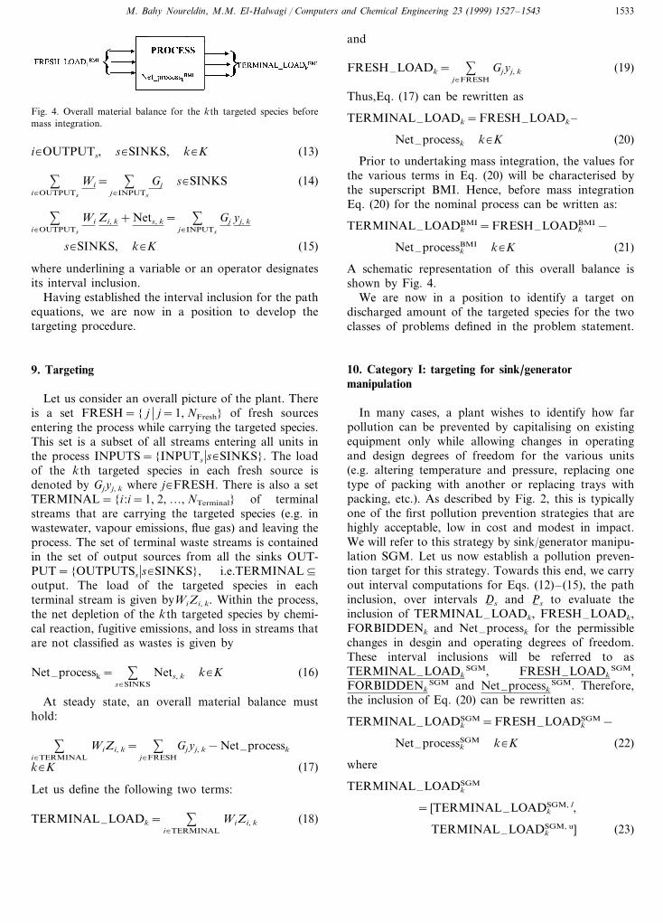
Fig. 4. Overall material balance for the kth targeted species beforemass integration.
and
FRESH–LOADk= %j�FRESH
Gjyj, k (19)
Thus,Eq. (17) can be rewritten as
TERMINAL–LOADk=FRESH–LOADk–
Net–processk k�K (20)
Prior to undertaking mass integration, the values forthe various terms in Eq. (20) will be characterised bythe superscript BMI. Hence, before mass integrationEq. (20) for the nominal process can be written as:
TERMINAL–LOADkBMI=FRESH–LOADk
BMI−
Net–processkBMI k�K (21)
A schematic representation of this overall balance isshown by Fig. 4.
We are now in a position to identify a target ondischarged amount of the targeted species for the twoclasses of problems defined in the problem statement.
10. Category I: targeting for sink/generatormanipulation
In many cases, a plant wishes to identify how farpollution can be prevented by capitalising on existingequipment only while allowing changes in operatingand design degrees of freedom for the various units(e.g. altering temperature and pressure, replacing onetype of packing with another or replacing trays withpacking, etc.). As described by Fig. 2, this is typicallyone of the first pollution prevention strategies that arehighly acceptable, low in cost and modest in impact.We will refer to this strategy by sink/generator manipu-lation SGM. Let us now establish a pollution preven-tion target for this strategy. Towards this end, we carryout interval computations for Eqs. (12)–(15), the pathinclusion, over intervals D6 s and P6 s to evaluate theinclusion of TERMINAL–LOADk, FRESH–LOADk,FORBIDDENk and Net–processk for the permissiblechanges in desgin and operating degrees of freedom.These interval inclusions will be referred to asTERMINAL–LOADk
SGM, FRESH–LOADkSGM,
FORBIDDENkSGM and Net–processk
SGM. Therefore,the inclusion of Eq. (20) can be rewritten as:
TERMINAL–LOADkSGM=FRESH–LOADk
SGM−
Net–processkSGM k�K (22)
where
TERMINAL–LOADkSGM
= [TERMINAL–LOADkSGM, l,
TERMINAL–LOADkSGM, u] (23)
i�OUTPUTs, s�SINKS, k�K (13)
%i�OUTPUTs
Wi= %j�INPUTs
Gj s�SINKS (14)
%i�OUTPUTs
Wi Zi, k+Nets, k= %j�INPUTs
Gj yj, k
s�SINKS, k�K (15)
where underlining a variable or an operator designatesits interval inclusion.
Having established the interval inclusion for the pathequations, we are now in a position to develop thetargeting procedure.
9. Targeting
Let us consider an overall picture of the plant. Thereis a set FRESH={ j � j=1, NFresh} of fresh sourcesentering the process while carrying the targeted species.This set is a subset of all streams entering all units inthe process INPUTS={INPUTs �s�SINKS}. The loadof the kth targeted species in each fresh source isdenoted by Gjyj, k where j�FRESH. There is also a setTERMINAL={i :i=1, 2, …, NTerminal} of terminalstreams that are carrying the targeted species (e.g. inwastewater, vapour emissions, flue gas) and leaving theprocess. The set of terminal waste streams is containedin the set of output sources from all the sinks OUT-PUT={OUTPUTSs �s�SINKS}, i.e.TERMINAL¤output. The load of the targeted species in eachterminal stream is given byWiZi, k. Within the process,the net depletion of the kth targeted species by chemi-cal reaction, fugitive emissions, and loss in streams thatare not classified as wastes is given by
Net–processk= %s�SINKS
Nets, k k�K (16)
At steady state, an overall material balance musthold:
%i�TERMINAL
WiZi, k= %j�FRESH
Gjyj, k−Net–processk
k�K (17)
Let us define the following two terms:
TERMINAL–LOADk= %i�TERMINAL
WiZi, k (18)
M. Bahy Noureldin, M.M. El-Halwagi / Computers and Chemical Engineering 23 (1999) 1527–15431534
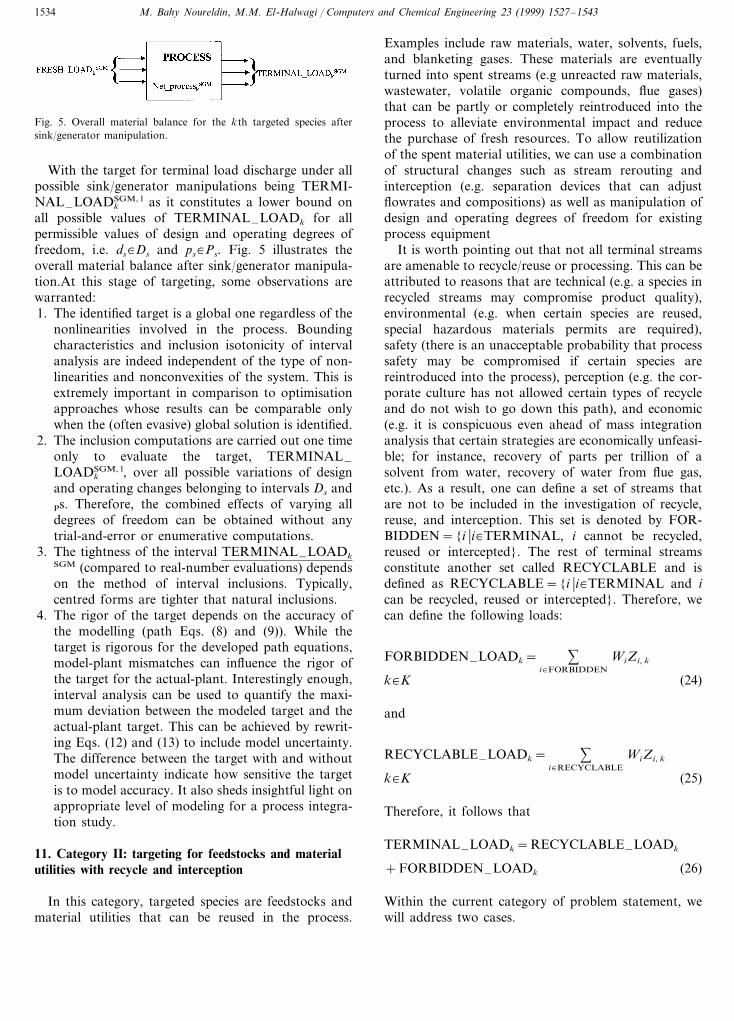
Fig. 5. Overall material balance for the kth targeted species aftersink/generator manipulation.
Examples include raw materials, water, solvents, fuels,and blanketing gases. These materials are eventuallyturned into spent streams (e.g unreacted raw materials,wastewater, volatile organic compounds, flue gases)that can be partly or completely reintroduced into theprocess to alleviate environmental impact and reducethe purchase of fresh resources. To allow reutilizationof the spent material utilities, we can use a combinationof structural changes such as stream rerouting andinterception (e.g. separation devices that can adjustflowrates and compositions) as well as manipulation ofdesign and operating degrees of freedom for existingprocess equipment
It is worth pointing out that not all terminal streamsare amenable to recycle/reuse or processing. This can beattributed to reasons that are technical (e.g. a species inrecycled streams may compromise product quality),environmental (e.g. when certain species are reused,special hazardous materials permits are required),safety (there is an unacceptable probability that processsafety may be compromised if certain species arereintroduced into the process), perception (e.g. the cor-porate culture has not allowed certain types of recycleand do not wish to go down this path), and economic(e.g. it is conspicuous even ahead of mass integrationanalysis that certain strategies are economically unfeasi-ble; for instance, recovery of parts per trillion of asolvent from water, recovery of water from flue gas,etc.). As a result, one can define a set of streams thatare not to be included in the investigation of recycle,reuse, and interception. This set is denoted by FOR-BIDDEN={i �i�TERMINAL, i cannot be recycled,reused or intercepted}. The rest of terminal streamsconstitute another set called RECYCLABLE and isdefined as RECYCLABLE={i �i�TERMINAL and ican be recycled, reused or intercepted}. Therefore, wecan define the following loads:
FORBIDDEN–LOADk= %i�FORBIDDEN
WiZi, k
k�K (24)
and
RECYCLABLE–LOADk= %i�RECYCLABLE
WiZi, k
k�K (25)
Therefore, it follows that
TERMINAL–LOADk=RECYCLABLE–LOADk
+FORBIDDEN–LOADk (26)
Within the current category of problem statement, wewill address two cases.
With the target for terminal load discharge under allpossible sink/generator manipulations being TERMI-NAL–LOADk
SGM, l as it constitutes a lower bound onall possible values of TERMINAL–LOADk for allpermissible values of design and operating degrees offreedom, i.e. ds�Ds and ps�Ps. Fig. 5 illustrates theoverall material balance after sink/generator manipula-tion.At this stage of targeting, some observations arewarranted:1. The identified target is a global one regardless of the
nonlinearities involved in the process. Boundingcharacteristics and inclusion isotonicity of intervalanalysis are indeed independent of the type of non-linearities and nonconvexities of the system. This isextremely important in comparison to optimisationapproaches whose results can be comparable onlywhen the (often evasive) global solution is identified.
2. The inclusion computations are carried out one timeonly to evaluate the target, TERMINAL–LOADk
SGM, l, over all possible variations of designand operating changes belonging to intervals Ds andPs. Therefore, the combined effects of varying alldegrees of freedom can be obtained without anytrial-and-error or enumerative computations.
3. The tightness of the interval TERMINAL–LOADkSGM (compared to real-number evaluations) dependson the method of interval inclusions. Typically,centred forms are tighter that natural inclusions.
4. The rigor of the target depends on the accuracy ofthe modelling (path Eqs. (8) and (9)). While thetarget is rigorous for the developed path equations,model-plant mismatches can influence the rigor ofthe target for the actual-plant. Interestingly enough,interval analysis can be used to quantify the maxi-mum deviation between the modeled target and theactual-plant target. This can be achieved by rewrit-ing Eqs. (12) and (13) to include model uncertainty.The difference between the target with and withoutmodel uncertainty indicate how sensitive the targetis to model accuracy. It also sheds insightful light onappropriate level of modeling for a process integra-tion study.
11. Category II: targeting for feedstocks and materialutilities with recycle and interception
In this category, targeted species are feedstocks andmaterial utilities that can be reused in the process.

M. Bahy Noureldin, M.M. El-Halwagi / Computers and Chemical Engineering 23 (1999) 1527–1543 1535
Fig. 6. A generic process before recycle.
SGM. An example of this case is encountered when the netgeneration/depletion by reaction systems is a minorcontributor to the overall load of pollutants in terminalstreams.
In this case, reduction in terminal load is criticallydependent on reduction in fresh load. Indeed, as can beseen from Eq. (20), for each unit mass reduction in freshload there is an equal reduction in terminal load. Inaddition to sink/generator manipulation addressed inthe previous section, there is an additional way to reducefresh load. This can be achieved by replacing fresh usageof the targeted species with recycled species from termi-nal streams. In principle, it is possible to replace anyfresh source of the targeted species with an equivalentamount of recycle from a terminal or an in-processstream. If the composition and flowrate of the recycledstream meets constraints Eqs. (6) and (7) for unitsemploying fresh sources, then we can undertake directrecycle from those terminal streams to those unitsemploying fresh sources. On the other hand, if flowrateand/or composition constraints are not met, then theterminal streams must be intercepted to render them ina condition that allows replacement of fresh sources. Itis important to note that these recycle activities shouldbe limited to rerouting terminal streams (with or withoutinterception) to units that employ fresh resources. Inorder to illustrate this observation, let us consider theprocess shown in Fig. 6. In this process, three freshstreams ( j=1–3) carry the targeted species. The re-quired input load of the kth targeted species in thesestreams is denoted by Fresh–Loadk, j. The targetedspecies leave the process in four terminal streams; two ofwhich (i=1, 2) are recyclable (with or without intercep-tion) and the other two (i=3, 4) are forbidden frombeing recycled. The total load from the four terminalstreams is given by Terminal–Loadk, 1+Terminal–Loadk, 2+Terminal–Loadk, 3+Terminal–Loadk, 4.
Let us first consider recycle from terminal streams tounits that do not employ fresh resources. For instance,as shown by Fig. 7a, let us recycle a load of Rk, 1 fromi=1 to the inlet of unit c5 and a load of Rk, 2 from i=2to the inlet of unit c4. Since we are dealing with thecase where recycle activities have no effect on Net–processk, the loads in the individual terminal streams aresimply redistributed with the total terminal load remain-ing the same (Terminal–Loadk, 1+Terminal–Loadk, 2+Terminal–Loadk, 3+Terminal–Loadk, 4).This observation can also be deduced from Eq. (20) bynoting that since the fresh loads entering the processremain constant, and since this case deals with unaf-fected Net–processk, the total terminal load will remainthe same. Therefore, in this case, sinks that do notemploy fresh sources of the targeted species are poordestinations for recycle.
Fig. 7. (a) The process after recycle to poor sinks (total terminal loadof pollutants is the unchanged). (b) The process after recycle toproper sinks to replace fresh loads of targeted species (total terminalload of pollutants is the reduced). (c) Recycle to replace fresh sourcesusing in-plant and terminal streams.
11.1. Net generation/depletion of the targeted species isindependent of stream rerouting acti6ities
Let us first consider the case where the net generation/depletion of the targeted species is independent of streamrerouting activities. In this case, the term Net–processk
is indifferent to any changes in stream allocation. Exam-ples of this case are:
Intervals defined by constraints Eqs. (6) and (7) havenarrow widths. Hence, any recycled stream (with orwithout interception) must have flowrate, composition,and other properties that are almost identical to theoriginal stream fed to the unit. Therefore, after recycle,the performance of units involving net generation/deple-tion will remain the same as it was before recycle.
When net generation/depletion of units is insensitiveto the constraints Eqs. (6) and (7). This insensitivity canbe assessed by evaluating the interval inclusion of theterm Nets, k for each unit s when inputs to units areallowed to vary within the intervals defined by con-straints Eqs. (6) and (7).
The term Net–processk is much smaller than the terms TERMINAL–LOADk
SGM and FRESH–LOADk
M. Bahy Noureldin, M.M. El-Halwagi / Computers and Chemical Engineering 23 (1999) 1527–15431536
Next, we consider recycles that reduce fresh loads.For instance, let us examine the effect of recycling aload of Rk, 1 from i=1 to the inlet of unit c2 and aload of Rk, 2 from i=2 to the inlet of unit c1. This isshown by Fig. 7b. The result of the fresh source re-placement is a net reduction of Rk, 1+Rk, 2 fromFRESH–LOADk and consequently (and consistentwith Eq. (20)) the total terminal loads are reduced byRk, 1+Rk, 2. It is worth noting that these appropriaterecycles are not limited to terminal streams. Instead,what is needed is the replacement of fresh loads withrecycled loads from an in-plant or a terminal source.For example, the same effect shown in Fig. 7b can beaccomplished by recycling (with or without intercep-tion) from in-plant sources (e.g. i=5) as shown in Fig.7c.
The foregoing discussion illustrates that in the casewhere the net generation/depletion of the targeted spe-cies is independent of stream rerouting activities, re-placement of fresh sources with recycled sources,reduces the term FRESH–LOADk and (according toEq. (20)) also reduces TERMINAL–LOADk. There-fore, the higher the replacement, the lower the terminaldischarge. The maximum amount of targeted species kthat can be recycled from terminal streams to replacefresh sources is limited by the lower of the two loads,i.e.
Maximum replaceable load in fresh sources
=min (FRESH–LOADk, TERMINAL–LOADk)
k�K (27)
Therefore, for this category the target can be iden-tified by performing inclusion calculations for the path-diagram over intervals Ds and Ps, evaluating theresulting intervals for TERMINAL–LOADk and com-paring with FRESH–LOADk according to Eq. (27) todetermine the maximum extent for recycle. The unrecy-cled load will then constitute the target.
It is worth pointing out that if the targeted speciescannot be rerouted from streams that are forbiddenfrom recycle to streams that are recyclable, then lessloads can be recycled to replace fresh sources and Eq.(27) becomes: Maximum recyclable load for species
k=min (FRESH–LOADk,
RECYCLABLE–LOADk) k�K (28)
In this case, the target can be identified by perform-ing inclusion calculations for the path-diagram overintervals Ds and Ps, evaluating the resulting intervalsfor RECYCLABLE–LOADk and comparing withFRESH–LOADk according to Eq. (28) to determinethe maximum extent for recycle. The unrecycled loadwill then constitute the target.
It is worth pointing out that the following interestingcases may be encountered:
RECYCLABLE–LOADkl]FRESH–LOADk
u (29)
where the superscripts l and u refer to the lower andupper bounds of evaluated intervals.
According to Eq. (28), we can only recycle a load ofFRESH–LOADk
u leaving us with a target for the netterminal discharge being RECYCLABLE–LOADk
l -FRESH–LOADk
u. This is the case of zero purchase offresh targeted species.
On the other hand, if
RECYCLABLE–LOADku5FRESH–LOADk
l (30)
Then according to Eq. (28), we can fully reuse therecyclable terminal streams leaving us with a zero-dis-charge target for the recyclable terminal streams and atarget on the net purchase of fresh resources ofFRESH–LOADk
l -RECYCLABLE–LOADku.
11.2. Net generation/depletion of the targeted species isdependent on stream rerouting acti6ities
As a result of sink/generator manipulation, recycleand interception, the various flowrates and composi-tions may change. However, they should be allowed tovary only within the intervals defined by constraintsEqs. (6) and (7). Therefore, regardless of the extent ofsink/generator manipulation, recycle and interception,constraints Eqs. (6) and (7) include all feasible inputs tothe units. Hence, we can now carry out the intervalcomputations for Eqs. (12)–(15) over intervals Eqs. (6)and (7), Ds and Ps to obtain the inclusion of TERMI-NAL–LOADk, FRESH–LOADk, and Net–processk
along with Eq. (27) or Eq. (28) can be used to evaluatethe maximum extent of recycle and hence identify thetarget as in the previous case. Again, this is a one-timecalculation that can evaluate the target for minimumdischarge.
In order to demonstrate the devised targeting proce-dure, let us consider the following case study.
12. Case study: reduction of water usage and dischargein a tire-to-fuel plant
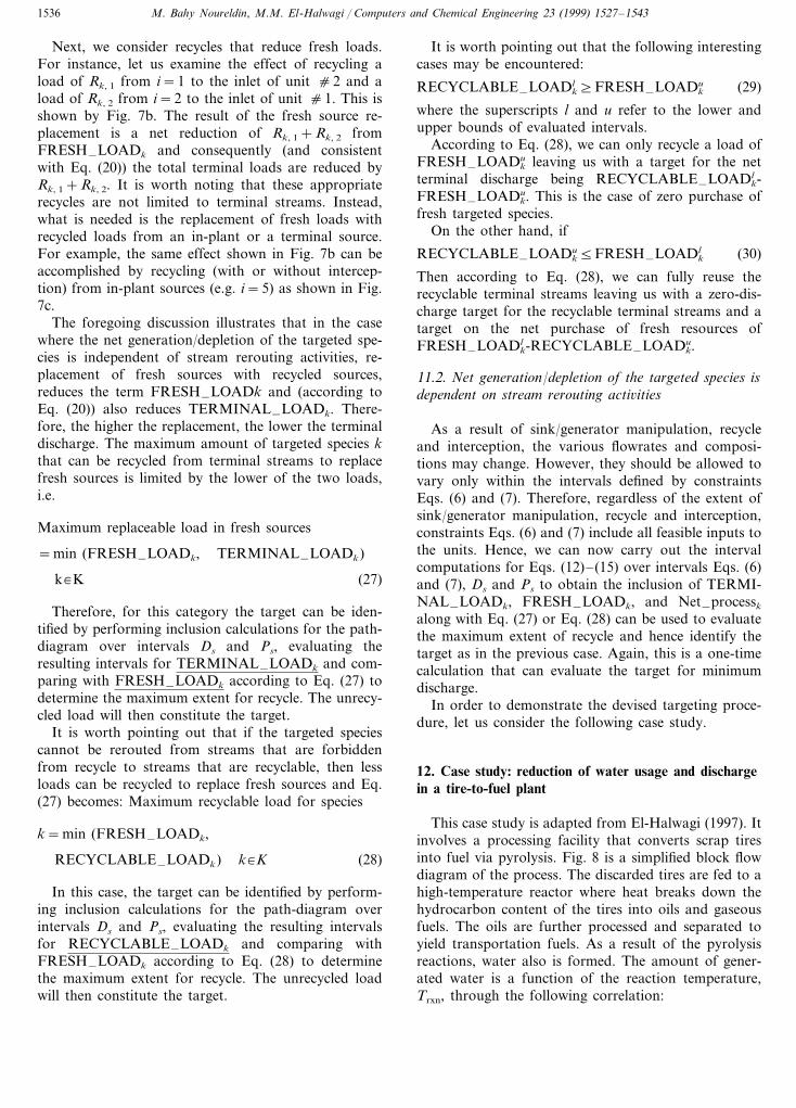
This case study is adapted from El-Halwagi (1997). Itinvolves a processing facility that converts scrap tiresinto fuel via pyrolysis. Fig. 8 is a simplified block flowdiagram of the process. The discarded tires are fed to ahigh-temperature reactor where heat breaks down thehydrocarbon content of the tires into oils and gaseousfuels. The oils are further processed and separated toyield transportation fuels. As a result of the pyrolysisreactions, water also is formed. The amount of gener-ated water is a function of the reaction temperature,Trxn, through the following correlation:
M. Bahy Noureldin, M.M. El-Halwagi / Computers and Chemical Engineering 23 (1999) 1527–1543 1537
Fig. 8. Simplified flowsheet of tire-to-fuel plant solution.
Wrxn=0.152+ (5.37−7.84×10⁻³Trxn)e(27.4−0.04Trxn)
(31)
Where Wrxn is in kg/s and Trxn is in K. At present, thereactor is operated at 690 K which leads to the genera-tion of 0.12 kg water/s. In order to maintain acceptableproduct quality, the reaction temperature should bekept within the following range:
6905Trxn(K)5740 (32)
The reactor off-gases are cooled to condense lightoils. The condensation is decanted into two layers:aqueous and organic. The aqueous layer is a wastewa-ter stream which contains phenol as the primary pollu-tant. The flow rate of this wastewater stream isdesignated as W1. The organic layer is mixed with theliquid products of the reactor. and fed to finishing. Agaseous waste leaves the finishing unit and is flared. Toprevent the back-propagation of fire from the flare, aseal pot is used. An aqueous stream whose flowrate isG2 is passed through the seal pot to form a buffer zonebetween the fire and the source of the flare gas. Toavoid accumulation of impurities in the seal pot, anequivalent flowrate of wastewater stream, W2, is with-drawn from it.
Tire shredding is achieved by using high-pressurewater-jets. The shredded tires are fed to the processwhile the spent water is filtered. The wet cake collectedfrom the filtration system is forwarded to solid wastehandling. The filtrate is mixed with fresh water-jetmakeup G1 to compensate for water losses with the wetcake W3 and the shredded tires. The mixture of filtrateand water makeup is fed to a high-pressure compres-sion station for recycle to the shredding unit. The
flowrate of water-jet makeup depends on the appliedpressure coming out of the compression stage Pcomp viathe following expression:
G1=0.47e−0.009Pcomp (33)
where G1 is in kg/s and Pcomp is in atm. In order toachieve acceptable shredding, the jet pressure may bevaried within the following range:
705Pcomp(atm)590 (34)
At present, Pcomp is 70 atm which requires a water-jetmake-up flowrate of 0.25 kg/s.The water lost in thecake is related to the mass flowrate of the water-jetmakeup through: W3=0.4 G1
In addition to the water in the wet cake, the plant hastwo primary sources for wastewater; from the decanter(W1) and from the seal pot (W2). At present, the valuesof W1, W2, and W3 are 0.27, 0.15, and 0.10 kg/s,respectively. The wastewater from the decanter containsabout 500 ppm of phenol. Within the range of allow-able operating changes, this concentration can be as-sumed to remain constant. At present, the wastewaterfrom the seal pot contains no phenol. The plant hasbeen shipping the wastewater streams W1 and W2 foroff-site treatment. The cost of wastewater transporta-tion and treatment is $ 0.10/kg leading to a wastewatertreatment cost of approximately $ 1.33 million/year. W3
has been processed on site. Because of the characteris-tics of W3, the plant does not allow its recycle back tothe process even after waste handling processing (aforbidden stream). The plant wishes to reduce (or ifpossible to stop) off-site treatment of wastewaterstreams W1 and W2 to avoid cost of off-site treatment
M. Bahy Noureldin, M.M. El-Halwagi / Computers and Chemical Engineering 23 (1999) 1527–15431538
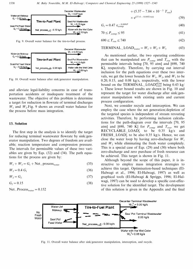
Fig. 9. Overall water balance for the tire-to-fuel process.
+ (5.37−7.84×10⁻³ Trxn)
×e(27.4−0.04Trxn) (39)
G1=0.47 e−0.009Pcomp (40)
705Pcomp595 (41)
6905Trxn5740 (42)
TERMINAL–LOADwater=W1+W2+W3 (43)
As mentioned earlier, the two operating conditionsthat can be manipulated are Pcomp and Trxn with thepermissible intervals being [70, 95 atm] and [690, 740K], respectively. Therefore, by carrying out intervalinclusion for the path equations over these two inter-vals, we get the lower bounds for W1, W2, and W3 to be0.20, 0.15, and 0.08 kg/s, respectively, with the lowerbound on the TERMINAL–LOADSGM
water being 0.43 kg/s. These lower bound results are shown in Fig. 10 andrepresent the target for water discharge after sink/gen-erator manipulation with existing units and currentprocess configuration.
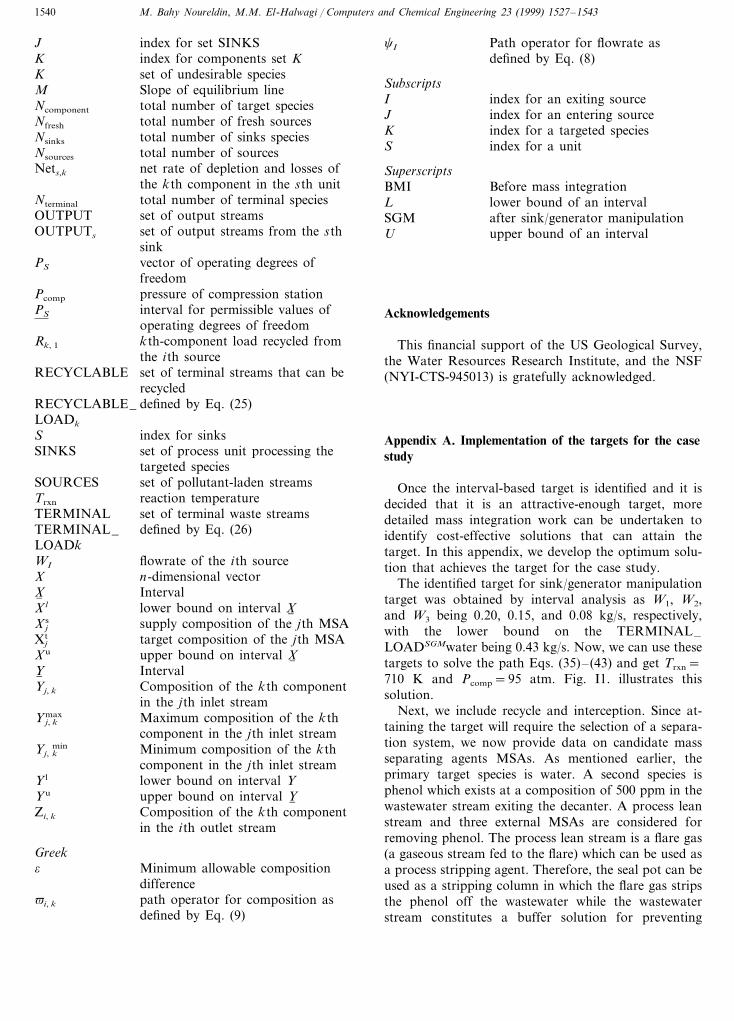
Next, we consider recycle and interception. We canemploy the case where the net generation/depletion ofthe targeted species is independent of stream reroutingactivities. Therefore, by performing inclusion calcula-tions for the path-diagram over the intervals [70, 95atm] and [690, 740 K] for Pcomp and Trxn, we getRECYCLABLE–LOADk
l to be 0.35 kg/s andFRESH–LOADk
l to be also 0.35 kg/s. Hence, we canclose the water loop by having zero-discharge for W1
and W2 while eliminating the fresh water completely.This is a special case of Eqs. (29) and (30) where bothzero-discharge and zero purchase of fresh resource canbe achieved. This target is shown in Fig. 11.
Although beyond the scope of this paper, it is in-structive to employ mass integration strategies toachieve this target. Optimisation-based techniques (El-Halwagi et al., 1996; El-Halwagi, 1997) as well asgraphical tools (El-Halwagi & Spriggs, 1996; El-Hal-wagi, 1997) can be used to develop a specific cost-effec-tive solution for the identified target. The developmentof this solution is given in the Appendix and the final
Fig. 10. Overall water balance after sink/generator manipulation.
and alleviate legal-liability concerns in case of trans-portation accidents or inadequate treatment of thewastewater. The objective of this problem is determinea target for reduction in flowrate of terminal dischargesW1 and W2.Fig. 9 shows an overall water balance forthe process before mass integration.
13. Solution
The first step in the analysis is to identify the targetfor reducing terminal wastewater flowrate by sink/gen-erator manipulation. Two degrees of freedom are avail-able; reaction temperature and compression pressure.The intervals for permissible values of these two vari-ables are given by Eqs. (32) and (34). The path equa-tions for the process are given by:
W1+W3=G1+Net–processwater (35)
W3=0.4 G1 (36)
W2=G2 (37)
G2=0.15 (38)
Net–Processwater=0.152
Fig. 11. Overall water balance after sink/generator manipulation, interception, and recycle.

M. Bahy Noureldin, M.M. El-Halwagi / Computers and Chemical Engineering 23 (1999) 1527–1543 1539
Fig. 12. Solution to the case study (thick lines correspond to process changes).
solution is shown by Fig. 12. It involves the increase ofreaction temperature to 710 K and the increase ofcompression pressure to 95 atm. The solution alsoincludes direct recycle from the decanter to the seal potand an intercepted recycle (using stripping) from theseal pot to the compression station.
14. Conclusions
This work has presented a systematic framework foridentifying pollution prevention targets ahead of de-tailed design. Interval analysis and mass integrationwere employed to establish bounds on maximum extentof reducing terminal discharges. In particular, two im-portant classes of problems were considered. In the firstcategory, targets were identified for pollution preven-tion by manipulating design and operating degrees offreedom for existing process equipment. This is anindication of the inherent capability of the process toprevent pollution. In the second category, targeted spe-cies included feedstocks and material utilities that canbe reused in the process using structural changes suchas stream rerouting and interception as well as manipu-lation of design and operating degrees of freedom forexisting process equipment. Rigorous targets were alsoidentified for terminal discharge as well as fresh pur-chases. The devised interval-based targeting proceduresoffer several merits. They are rigorous without compu-tational intensity. A one-time computation is needed tobound the target. Furthermore, the identified targetsare guaranteed for globality regardless of the nonlinearnature of the system. Therefore, they offer significant
advantages over optimization-based approaches. If theidentified target is promising, then effort can be madeto use detailed mass integration strategies to identifyspecific cost-effective solutions that attain the target.
15. Nomenclature
C cost of MSA, $/kg MSAvector of design degrees of freedomds
Ds permissible values of design degreesof freedom
f(x) function of vector xF6 (X6 ) inclusion of function f over interval
X6set of terminal streams that cannotFORBIDDENbe recycled
FORBIDDEN_ defined by Eq. (24)LOADk
FRESH set of fresh inputs to the plantFRESH_LOADk load of the kth species entering the
process as defined by Eq. (19)flowrate of the jth sources enteringGj
the unitmaximum flowrate of the jth inletGj
max
to the unitGj
min minimum flowrate of the jth inletto the unitindex for set SOURCES and subsetITERMINAL
INPUTS set of input streamsINPUTs set of input streams to the sth sink
M. Bahy Noureldin, M.M. El-Halwagi / Computers and Chemical Engineering 23 (1999) 1527–15431540
index for set SINKSJK index for components set K
set of undesirable speciesKSlope of equilibrium lineMtotal number of target speciesNcomponent
total number of fresh sourcesNfresh
Nsinks total number of sinks speciestotal number of sourcesNsources
net rate of depletion and losses ofNets,k
the kth component in the sth unitNterminal total number of terminal species
set of output streamsOUTPUTset of output streams from the sthOUTPUTs
sinkvector of operating degrees ofPS
freedompressure of compression stationPcomp
interval for permissible values ofPS
operating degrees of freedomRk, 1 kth-component load recycled from
the ith sourceset of terminal streams that can beRECYCLABLErecycled
RECYCLABLE_ defined by Eq. (25)LOADk
index for sinksSSINKS set of process unit processing the
targeted speciesSOURCES set of pollutant-laden streams
reaction temperatureTrxn
TERMINAL set of terminal waste streamsdefined by Eq. (26)TERMINAL_
LOADkWI flowrate of the ith sourceX n-dimensional vector
IntervalX6Xl lower bound on interval X6
supply composition of the jth MSAXjs
Xjt target composition of the jth MSA
upper bound on interval X6Xu
Y6 IntervalYj, k Composition of the kth component
in the jth inlet streamMaximum composition of the kthYj, k
max
component in the jth inlet streamYj, k
min Minimum composition of the kthcomponent in the jth inlet stream
Y l lower bound on interval YYu upper bound on interval Y6Zi, k Composition of the kth component
in the ith outlet stream
GreekMinimum allowable compositiono
difference6i, k path operator for composition as
defined by Eq. (9)
Path operator for flowrate ascI
defined by Eq. (8)
SubscriptsI index for an exiting source
index for an entering sourceJindex for a targeted speciesK
S index for a unit
SuperscriptsBefore mass integrationBMIlower bound of an intervalL
SGM after sink/generator manipulationupper bound of an intervalU
Acknowledgements
This financial support of the US Geological Survey,the Water Resources Research Institute, and the NSF(NYI-CTS-945013) is gratefully acknowledged.
Appendix A. Implementation of the targets for the casestudy
Once the interval-based target is identified and it isdecided that it is an attractive-enough target, moredetailed mass integration work can be undertaken toidentify cost-effective solutions that can attain thetarget. In this appendix, we develop the optimum solu-tion that achieves the target for the case study.
The identified target for sink/generator manipulationtarget was obtained by interval analysis as W1, W2,and W3 being 0.20, 0.15, and 0.08 kg/s, respectively,with the lower bound on the TERMINAL–LOADSGMwater being 0.43 kg/s. Now, we can use thesetargets to solve the path Eqs. (35)–(43) and get Trxn=710 K and Pcomp=95 atm. Fig. I1. illustrates thissolution.
Next, we include recycle and interception. Since at-taining the target will require the selection of a separa-tion system, we now provide data on candidate massseparating agents MSAs. As mentioned earlier, theprimary target species is water. A second species isphenol which exists at a composition of 500 ppm in thewastewater stream exiting the decanter. A process leanstream and three external MSAs are considered forremoving phenol. The process lean stream is a flare gas(a gaseous stream fed to the flare) which can be used asa process stripping agent. Therefore, the seal pot can beused as a stripping column in which the flare gas stripsthe phenol off the wastewater while the wastewaterstream constitutes a buffer solution for preventing

M. Bahy Noureldin, M.M. El-Halwagi / Computers and Chemical Engineering 23 (1999) 1527–1543 1541
Fig. I1. Flowsheet after sink/generator manipulation.
back-propagation of fire. Three external MSAs areconsidered: a solvent extractant (S2), an adsorbent (S3),and a stripping agent (S4). The data for the candidateMSAs are given in Table I1. The equilibrium data forthe transfer of the pollutant from the waste stream tothe jth MSA is given by Table I1 where m is the slopeof equilibrium function, o is the minimum allowablecomposition difference
Water may be recycled to two sinks; the seal pot andthe water-jet compression station. The following con-straints on flowrate and composition of the pollutant(phenol) should be satisfied:
Seal pot:1. 0.105 flowrate of feed water (kg/s)50.202. 05 phenol content of feed water (ppm)550
Makeup to water-jet compression station1. 0.185 flowrate of makeup water (kg/s)50.202. 05 phenol content of makeup water (ppm)550Next, we represent the problem from a species view-point as shown in Fig. I2.
By undertaking source-sink mapping analysis (El-
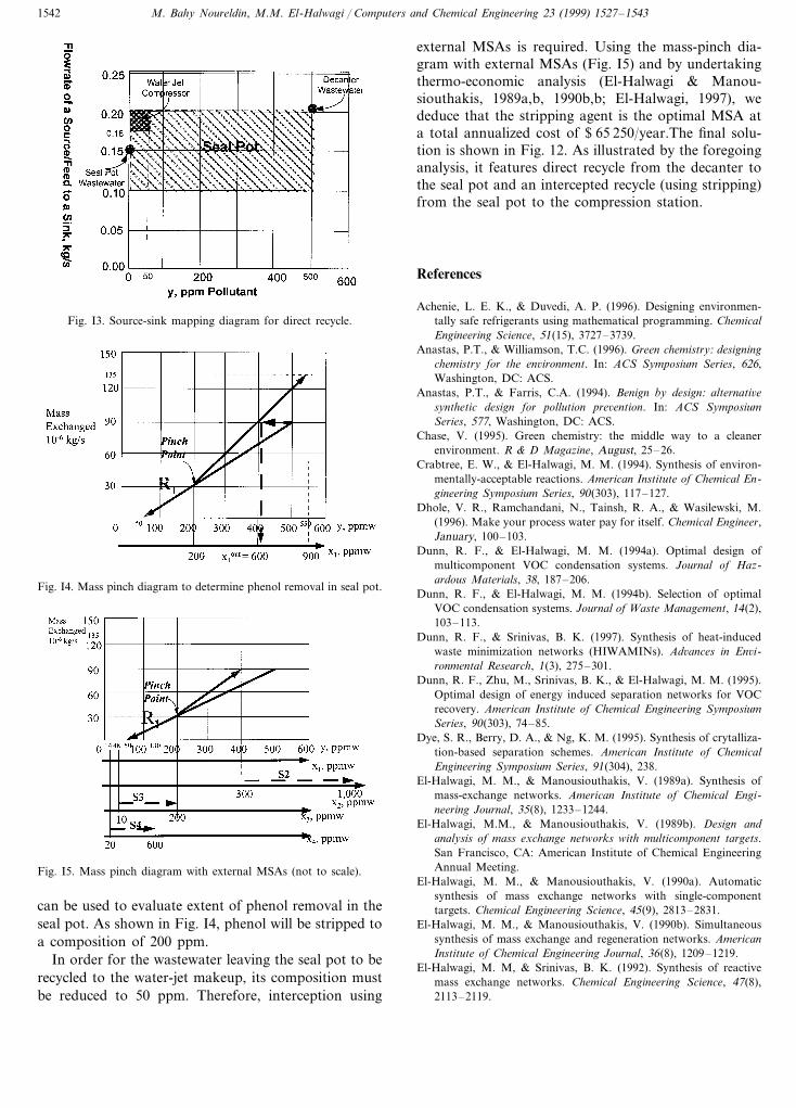
Halwagi & Spriggs, 1996; El-Halwagi, 1997), we iden-tify a direct-recycle opportunity from the dcanterwastewater to the seal pot (Fig. I3).Since the flare gas inthe seal pot is a process MSA, the mass-pinch diagram
Fig. I2. Problem from a species viewpoint.
Table I1Data for the MSAs of the tire pyrolysis problem
C $ TAC/kgEquilibrium o ppmw phenolStream Target compositionUpper bound on Supply composition(ppmw phenol) xj
s (ppmw phenol) xjtflowrate (kg/s) MSAconstant (m)
900 0.5 200S1 –0.15 200300� 1000 1.0 100 0.001S2
200S3 0.8� 50 0.020100.040500.2600� 20S4
M. Bahy Noureldin, M.M. El-Halwagi / Computers and Chemical Engineering 23 (1999) 1527–15431542
Fig. I3. Source-sink mapping diagram for direct recycle.
external MSAs is required. Using the mass-pinch dia-gram with external MSAs (Fig. I5) and by undertakingthermo-economic analysis (El-Halwagi & Manou-siouthakis, 1989a,b, 1990b,b; El-Halwagi, 1997), wededuce that the stripping agent is the optimal MSA ata total annualized cost of $ 65 250/year.The final solu-tion is shown in Fig. 12. As illustrated by the foregoinganalysis, it features direct recycle from the decanter tothe seal pot and an intercepted recycle (using stripping)from the seal pot to the compression station.
References
Achenie, L. E. K., & Duvedi, A. P. (1996). Designing environmen-tally safe refrigerants using mathematical programming. ChemicalEngineering Science, 51(15), 3727–3739.
Anastas, P.T., & Williamson, T.C. (1996). Green chemistry: designingchemistry for the en6ironment. In: ACS Symposium Series, 626,Washington, DC: ACS.
Anastas, P.T., & Farris, C.A. (1994). Benign by design: alternati6esynthetic design for pollution pre6ention. In: ACS SymposiumSeries, 577, Washington, DC: ACS.
Chase, V. (1995). Green chemistry: the middle way to a cleanerenvironment. R & D Magazine, August, 25–26.
Crabtree, E. W., & El-Halwagi, M. M. (1994). Synthesis of environ-mentally-acceptable reactions. American Institute of Chemical En-gineering Symposium Series, 90(303), 117–127.
Dhole, V. R., Ramchandani, N., Tainsh, R. A., & Wasilewski, M.(1996). Make your process water pay for itself. Chemical Engineer,January, 100–103.
Dunn, R. F., & El-Halwagi, M. M. (1994a). Optimal design ofmulticomponent VOC condensation systems. Journal of Haz-ardous Materials, 38, 187–206.
Dunn, R. F., & El-Halwagi, M. M. (1994b). Selection of optimalVOC condensation systems. Journal of Waste Management, 14(2),103–113.
Dunn, R. F., & Srinivas, B. K. (1997). Synthesis of heat-inducedwaste minimization networks (HIWAMINs). Ad6ances in En6i-ronmental Research, 1(3), 275–301.
Dunn, R. F., Zhu, M., Srinivas, B. K., & El-Halwagi, M. M. (1995).Optimal design of energy induced separation networks for VOCrecovery. American Institute of Chemical Engineering SymposiumSeries, 90(303), 74–85.
Dye, S. R., Berry, D. A., & Ng, K. M. (1995). Synthesis of crytalliza-tion-based separation schemes. American Institute of ChemicalEngineering Symposium Series, 91(304), 238.
El-Halwagi, M. M., & Manousiouthakis, V. (1989a). Synthesis ofmass-exchange networks. American Institute of Chemical Engi-neering Journal, 35(8), 1233–1244.
El-Halwagi, M.M., & Manousiouthakis, V. (1989b). Design andanalysis of mass exchange networks with multicomponent targets.San Francisco, CA: American Institute of Chemical EngineeringAnnual Meeting.
El-Halwagi, M. M., & Manousiouthakis, V. (1990a). Automaticsynthesis of mass exchange networks with single-componenttargets. Chemical Engineering Science, 45(9), 2813–2831.
El-Halwagi, M. M., & Manousiouthakis, V. (1990b). Simultaneoussynthesis of mass exchange and regeneration networks. AmericanInstitute of Chemical Engineering Journal, 36(8), 1209–1219.
El-Halwagi, M. M, & Srinivas, B. K. (1992). Synthesis of reactivemass exchange networks. Chemical Engineering Science, 47(8),2113–2119.
Fig. I4. Mass pinch diagram to determine phenol removal in seal pot.
Fig. I5. Mass pinch diagram with external MSAs (not to scale).
can be used to evaluate extent of phenol removal in theseal pot. As shown in Fig. I4, phenol will be stripped toa composition of 200 ppm.
In order for the wastewater leaving the seal pot to berecycled to the water-jet makeup, its composition mustbe reduced to 50 ppm. Therefore, interception using
M. Bahy Noureldin, M.M. El-Halwagi / Computers and Chemical Engineering 23 (1999) 1527–1543 1543
El-Halwagi, M. M. (1992). Synthesis of reverse osmosis networks forwaste reduction. American Institute of Chemical Engineering Jour-nal, 38(8), 1185–1198.
El-Halwagi, M. M. (1993). Optimal design of membrane hybridsystems for waste reduction. Separation Science Technology,28(1–3), 283–307.
El-Halwagi, M. M., Srinivas, B. K., & Dunn, R. F. (1995). Synthesisof optimal heat-induced separation networks. Chemical Engineer-ing Science, 50(1), 81–97.
El-Halwagi, M. M., Hamad, A. A., & Garrison, G. W. (1996).Synthesis of waste interception and allocation networks. AmericanInstitute of Chemical Engineering Journal, 42(11), 3087–3101.
El-Halwagi, M. M., & Spriggs, H. D. (1996). An integrated approachto cost and energy efficient pollution prevention. In Proceedings ofthe Fifth World Congress of Chemical Engineering, vol. III (pp.344–349). New York: AIChE.
El-Halwagi, M. M. (1997). Pollution pre6ention through process inte-gration: systematic design tools. San Diego: Academic.
El-Halwagi, M.M., & Spriggs, H.D. (1998). Employ mass integrationto achieve truly integrated process design. Chemical EngineeringProgress, 22–44.
El-Halwagi, M. M. (1999). Pollution prevention through mass inte-gration: systematic design tools. In Proceedings of internationalconference on process integration, vol. I (pp. 95–112). Copen-hagen, Denmark: PI99.
Evangelista, F. (1986). Improved graphical analytical method for thedesign of reverse osmosis desalination plants. Industrial and Engi-neering Chemistry Process Design De6elopment, 25(2), 366–375.
Garrison, G.W., Hamad, A.A., & El-Halwagi, M.M. (1995). Synthe-sis of waste-interception networks. American Institute of ChemicalEngineering Annual Meeting, Miami.
Hallale, N., & Fraser, D. M. (1997). Synthesis of cost optimum gastreating process using pinch analysis. In W. S. Ho, & R. G. Luo,Proceedings of the topical conference on separation science andtechnology: II (pp. 1708–1713). New York: American Institute ofChemical Engineering.
Hamad, A. A., & El-Halwagi, M. M. (1998). Simultaneous synthesisof mass separating agents and interception networks. Transactionsof the Institution of Chemical Engineers, 76(A), 376–388.
Huang, Y. L., & Fan, L. T. (1995). Intelligent process design andcontrol for in-plant waste minimization. In A. P. Rossiter, Wasteminimization through process design (pp. 165–180). New York:McGraw Hill.
Huang, Y. L., & Edgar, T. F. (1995). Knowledge based designapproach for the simultaneous minimization of waste generationand energy consumption in a petroleum refinery. In A. P.Rossiter, Waste minimization through process design (pp. 181–196). New York: McGraw Hill.
Joback, K. G. (1994). Solvent substitution for pollution prevention.American Institute of Chemical Engineering Symposium Series,90(303), 98–104.
Kiperstok, A., & Sharratt, P. N. (1995). On the optimization of massexchange networks for removal of pollutants. Transactions of theInstitution of Chemical Engineers (B), 73, 271–277.
Kovacs, Z., Friedler, F., & Fan, L. T. (1993). Recycling in aseparation process structure. American Institute of Chemical Engi-neering Journal, 39(6), 1087–1089.
Kuo, W. C. J., & Smith, R. (1998). Designing for the interactionsbetween water use and effluent treatment. Transactions of theInstitution of Chemical Engineers (A), 76, 287–301.
Linnhoff, B., & Hindmarsh, E. (1983). The pinch design method forheat exchanger networks. Chemical Engineering Science, 38(5),745–763.
Malone, M. F., & Doherty, M. F. (1995). Separation system synthesisfor nonideal liquid mixtures. American Institute of Chemical Engi-neering Symposium Series, 91(304), 9–18.
Moore, R. E. (1988). Reliability in computing: the role of inter6almethods in scientific computing. San Diego: Academic.
Parthasarathy, G., & El-Halwagi M.M. (1997). Mass integration formulticomponent nonideal systems. Los Angeles: American Instituteof Chemical Engineering Annual Meeting.
Parthasarathy, G., & El-Halwagi, M.M. (1999). Optimum mass inte-gration strategies for condensation and allocation of multicompo-nent VOCs. Chemical Engineering Science (in press).
Papalexandri, K. P., & Pistikopoulos, E. N. (1994). A multiperiodMINLP model for the synthesis of heat and mass exchangenetworks. Computers in Chemical Engineering, 18(12), 1125–1139.
Quesada, I., & Grossmann, I. E. (1995). Global optimization ofbilinear process networks with multicomponent flows. Computersin Chemical Engineering, 19(12), 1219–1242.
Ratschek, H., & Rokne, J. (1984a). Computer methods for the range offunctions. New York: Halsted/Wiley.
Ratschek, H., & Rokne, J. (1984b). New computer methods for globaloptimization. New York: Ellis Horwood/Wiley.
Richburg, A., & El-Halwagi, M. M. (1995). A graphical approach tothe optimal design of heat-induced separation networks for VOCrecovery. American Institute of Chemical Engineering SymposiumSeries, 91(304), 256–259.
Shelley, M.D., Parthasarathy G., & El-Halwagi, M.M. (1998). Clus-tering techniques for mass integration for complex hydrocarbonmixtures. Miami: American Institute of Chemical EngineeringAnnual Meeting.
Srinivas, B. K., & El-Halwagi, M. M. (1993). Optimal design ofpervaporation systems for waste reduction. Computers in Chemi-cal Engineering, 17(10), 957–970.
Srinivas, B. K., & El-Halwagi, M. M. (1994a). Synthesis of reactivemass-exchange networks with general nonlinear equilibrium func-tions. American Institute of Chemical Engineering Journal, 40(3),463–472.
Srinivas, B. K., & El-Halwagi, M. M. (1994b). Synthesis of combinedheat and reactive mass-exchange networks. Chemical EngineeringScience, 49(13), 2059–2074.
Wahnschafft, O. M., Jurian, T. P., & Westerberg, A. W. (1991).SPLIT: a separation process designer. Computers in ChemicalEngineering, 15, 565–581.
Wang, Y. P., & Smith, R. (1994). Wastewater minimization. ChemicalEngineering Science, 49(7), 981–1006.
Zhu, M., & El-Halwagi, M. M. (1995). Synthesis of flexible massexchange networks. Chemical Engineering Community, 138, 193–211.
.


![Interval Notation: ], not interval notationpgrant.weebly.com/uploads/2/3/2/7/23274454/6.3b_interval_notation.… · •Interval Notation: Uses different brackets to indicate an interval](https://img.pdfslide.net/doc/110x75/5f8344624904df613146ef90/interval-notation-not-interval-ainterval-notation-uses-different-brackets.jpg)