Embed Size (px)
Citation preview
ENOC 2017, June 25-30, 2017, Budapest, Hungary
Bifurcations in implicit map - application to Surface Location Error in millingprocesses
Adam K. Kiss∗, Daniel Bachrathy∗, and Gabor Stepan∗∗Department of Applied Mechanics, Budapest University of Technology and Economics, Budapest
Summary. In this contribution, a new type of stability problem is shown in milling operations, which are related to the surface quality.The machined Surface Location Error depends on the previously and actually resulted surface offset through the variation of the radialimmersion. Bifurcation analysis is presented for the governing nonlinear implicit map.
Introduction
In industry, milling is a widely used manufacturing method. Due to the intermittent behaviour of the milling processes,the cutting edges enter and exit the material periodically according to the applied radial immersion. This phenomenonleads to a periodic cutting force which always results forced vibration in the mechanical system. This vibration is copiedto the surface and creates the so-called Surface Location Error (SLE), which is an offset error defined by the largestdeviation between the machined and the desired surface [1, 2]. Since the forced vibration usually creates negligiblesurface roughness, this error could be compensated with a proper tool path modification. This type of surface error issignificant typically at resonant spindle speeds where large amplitude vibration can occur. During the prediction of thissurface error, the widely used methods do not consider that the SLE can influence the radial immersion. However, inthe case study [1], the measured vibration amplitude was in the range of the radial immersion. Moreover in case ofconsecutive immersions during roughing process, the actual and the preceding SLE modifies the entering and the exitingposition. In a previous study [3], the evaluation of the series of SLE values is investigated in a way that the actual pre-setradial immersion is modified by the SLE of the previous immersion only, which leads to an explicit map. In this paper,the actual SLE is considered by means of an implicit map, and the stability properties of the fix point and correspondingbifurcation curves are analysed.
Implicit map
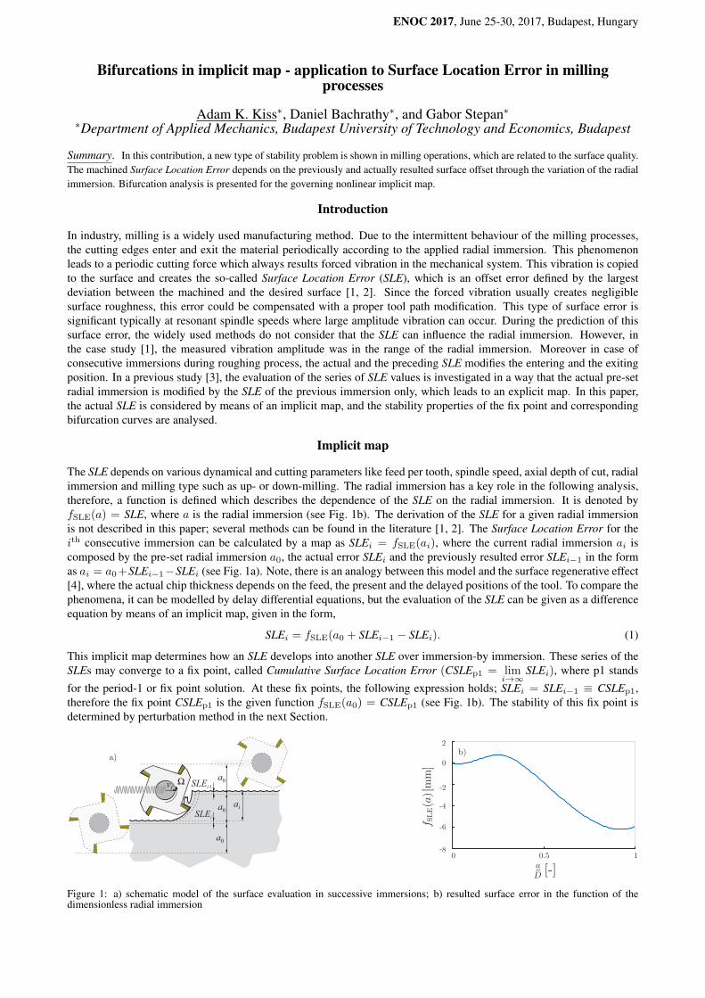
The SLE depends on various dynamical and cutting parameters like feed per tooth, spindle speed, axial depth of cut, radialimmersion and milling type such as up- or down-milling. The radial immersion has a key role in the following analysis,therefore, a function is defined which describes the dependence of the SLE on the radial immersion. It is denoted byfSLE(a) = SLE, where a is the radial immersion (see Fig. 1b). The derivation of the SLE for a given radial immersionis not described in this paper; several methods can be found in the literature [1, 2]. The Surface Location Error for theith consecutive immersion can be calculated by a map as SLEi = fSLE(ai), where the current radial immersion ai iscomposed by the pre-set radial immersion a0, the actual error SLEi and the previously resulted error SLEi−1 in the formas ai = a0+SLEi−1−SLEi (see Fig. 1a). Note, there is an analogy between this model and the surface regenerative effect[4], where the actual chip thickness depends on the feed, the present and the delayed positions of the tool. To compare thephenomena, it can be modelled by delay differential equations, but the evaluation of the SLE can be given as a differenceequation by means of an implicit map, given in the form,
SLEi = fSLE(a0 + SLEi−1 − SLEi). (1)
This implicit map determines how an SLE develops into another SLE over immersion-by immersion. These series of theSLEs may converge to a fix point, called Cumulative Surface Location Error (CSLEp1 = lim
i→∞SLEi), where p1 stands
for the period-1 or fix point solution. At these fix points, the following expression holds; SLEi = SLEi−1 ≡ CSLEp1,therefore the fix point CSLEp1 is the given function fSLE(a0) = CSLEp1 (see Fig. 1b). The stability of this fix point isdetermined by perturbation method in the next Section.
Ω SLEi-1
ai
a0
a0SLEi
a0vf
[-]
[mm]
b)a)
Figure 1: a) schematic model of the surface evaluation in successive immersions; b) resulted surface error in the function of thedimensionless radial immersion
ENOC 2017, June 25-30, 2017, Budapest, Hungary
Period-2 solutions
[-]
[-] [-][mm
]
[mm]
[-]
[-]
c)b)a)
[mm]
Flip bif. points
stableCSLE p1
unstable CSLE p1
stableCSLE p2
1,2
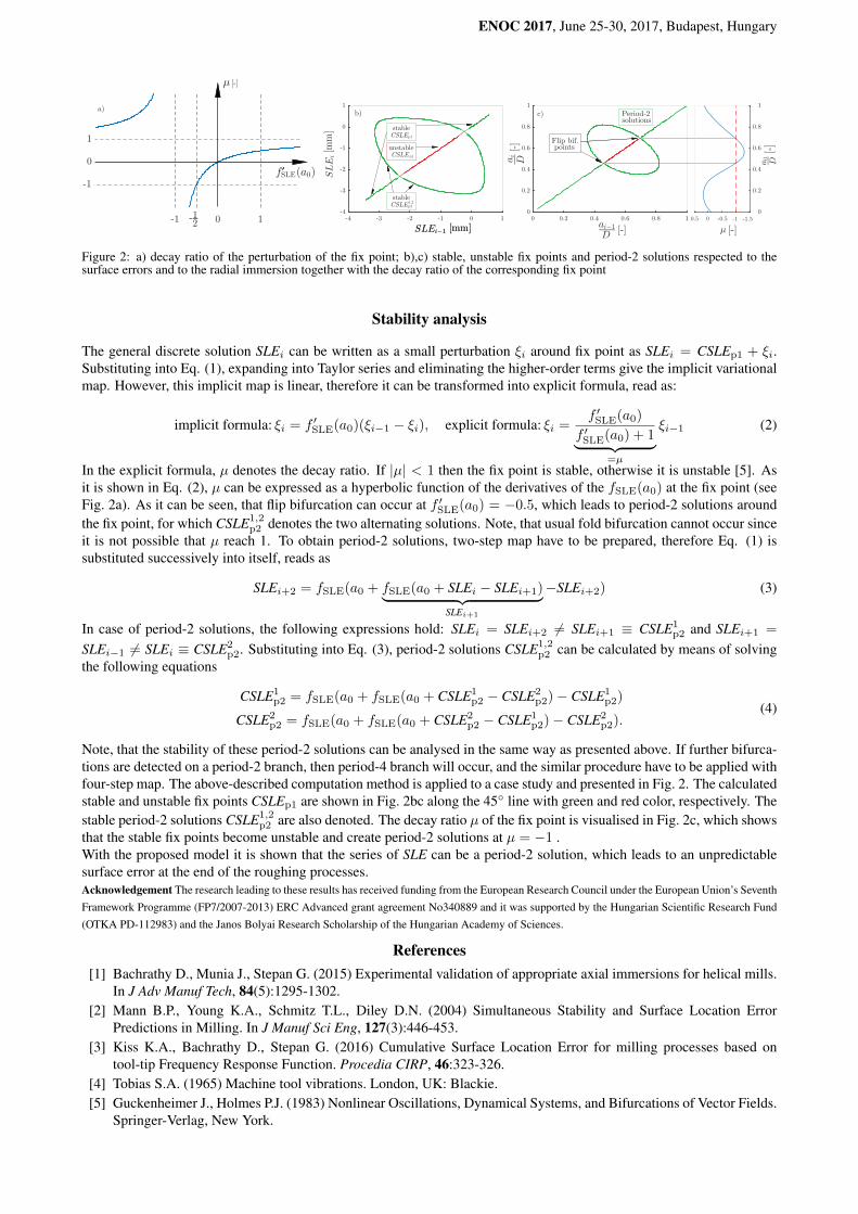
Figure 2: a) decay ratio of the perturbation of the fix point; b),c) stable, unstable fix points and period-2 solutions respected to thesurface errors and to the radial immersion together with the decay ratio of the corresponding fix point
Stability analysis
The general discrete solution SLEi can be written as a small perturbation ξi around fix point as SLEi = CSLEp1 + ξi.Substituting into Eq. (1), expanding into Taylor series and eliminating the higher-order terms give the implicit variationalmap. However, this implicit map is linear, therefore it can be transformed into explicit formula, read as:
implicit formula: ξi = f ′SLE(a0)(ξi−1 − ξi), explicit formula: ξi =f ′SLE(a0)
f ′SLE(a0) + 1︸ ︷︷ ︸=µ
ξi−1 (2)
In the explicit formula, µ denotes the decay ratio. If |µ| < 1 then the fix point is stable, otherwise it is unstable [5]. Asit is shown in Eq. (2), µ can be expressed as a hyperbolic function of the derivatives of the fSLE(a0) at the fix point (seeFig. 2a). As it can be seen, that flip bifurcation can occur at f ′SLE(a0) = −0.5, which leads to period-2 solutions aroundthe fix point, for which CSLE1,2
p2 denotes the two alternating solutions. Note, that usual fold bifurcation cannot occur sinceit is not possible that µ reach 1. To obtain period-2 solutions, two-step map have to be prepared, therefore Eq. (1) issubstituted successively into itself, reads as
SLEi+2 = fSLE(a0 + fSLE(a0 + SLEi − SLEi+1)︸ ︷︷ ︸SLEi+1
−SLEi+2) (3)
In case of period-2 solutions, the following expressions hold: SLEi = SLEi+2 6= SLEi+1 ≡ CSLE1p2 and SLEi+1 =
SLEi−1 6= SLEi ≡ CSLE2p2. Substituting into Eq. (3), period-2 solutions CSLE1,2
p2 can be calculated by means of solvingthe following equations
CSLE1p2 = fSLE(a0 + fSLE(a0 + CSLE1
p2 − CSLE2p2)− CSLE1
p2)
CSLE2p2 = fSLE(a0 + fSLE(a0 + CSLE2
p2 − CSLE1p2)− CSLE2
p2).(4)
Note, that the stability of these period-2 solutions can be analysed in the same way as presented above. If further bifurca-tions are detected on a period-2 branch, then period-4 branch will occur, and the similar procedure have to be applied withfour-step map. The above-described computation method is applied to a case study and presented in Fig. 2. The calculatedstable and unstable fix points CSLEp1 are shown in Fig. 2bc along the 45 line with green and red color, respectively. Thestable period-2 solutions CSLE1,2
p2 are also denoted. The decay ratio µ of the fix point is visualised in Fig. 2c, which showsthat the stable fix points become unstable and create period-2 solutions at µ = −1 .With the proposed model it is shown that the series of SLE can be a period-2 solution, which leads to an unpredictablesurface error at the end of the roughing processes.Acknowledgement The research leading to these results has received funding from the European Research Council under the European Union’s SeventhFramework Programme (FP7/2007-2013) ERC Advanced grant agreement No340889 and it was supported by the Hungarian Scientific Research Fund(OTKA PD-112983) and the Janos Bolyai Research Scholarship of the Hungarian Academy of Sciences.
References[1] Bachrathy D., Munia J., Stepan G. (2015) Experimental validation of appropriate axial immersions for helical mills.
In J Adv Manuf Tech, 84(5):1295-1302.[2] Mann B.P., Young K.A., Schmitz T.L., Diley D.N. (2004) Simultaneous Stability and Surface Location Error
Predictions in Milling. In J Manuf Sci Eng, 127(3):446-453.[3] Kiss K.A., Bachrathy D., Stepan G. (2016) Cumulative Surface Location Error for milling processes based on
tool-tip Frequency Response Function. Procedia CIRP, 46:323-326.[4] Tobias S.A. (1965) Machine tool vibrations. London, UK: Blackie.[5] Guckenheimer J., Holmes P.J. (1983) Nonlinear Oscillations, Dynamical Systems, and Bifurcations of Vector Fields.
Springer-Verlag, New York.