Embed Size (px)
Citation preview
Introduction: Part-1 1
CSCI 6781Advanced Computer Networks
Ram Dantu

Introduction: Part-1 2
Course Overview
Introduction: Part-1 3
Syllabus
This class IS about... Recent advances in Computer Networks New developments in Physical Layer, Layer
2 (ATM/MPLS), Layer 3 (mobile IP, ForCES), Layer 4 (SCTP) and application layers like SIP, MIDCOM, MobileIP, etc.
Vulnerability of these protocols, threat models
Wireless networks and handoff issues Working together and learning together ….
Introduction: Part-1 4
Background
My background Your background, thesis topic and why
are you talking this course Need some course to finish the degree Want to be network security engineer Want to be a hacker
Check your email often (atleast twice a day)
Office Hours and appointment (available most of the week days, get an appointment)
Introduction: Part-1 5
Grading
See website
Introduction: Part-1 6
Issues in Internet
Scalability QoS Security Availability
Introduction: Part-1 7
MPLS, Why
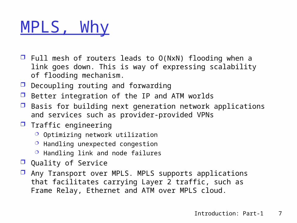
Full mesh of routers leads to O(NxN) flooding when a link goes down. This is way of expressing scalability of flooding mechanism.
Decoupling routing and forwarding Better integration of the IP and ATM worlds Basis for building next generation network applications and
services such as provider-provided VPNs Traffic engineering
Optimizing network utilization Handling unexpected congestion Handling link and node failures
Quality of Service Any Transport over MPLS. MPLS supports applications that
facilitates carrying Layer 2 traffic, such as Frame Relay, Ethernet and ATM over MPLS cloud.
Introduction: Part-1 8
Why SCTP
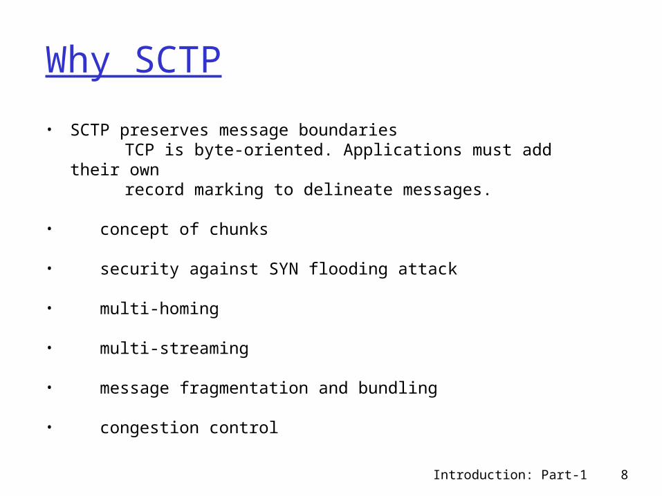
• SCTP preserves message boundaries TCP is byte-oriented. Applications must add their own record marking to delineate messages.
• concept of chunks
• security against SYN flooding attack
• multi-homing
• multi-streaming
• message fragmentation and bundling
• congestion control
Introduction: Part-1 9
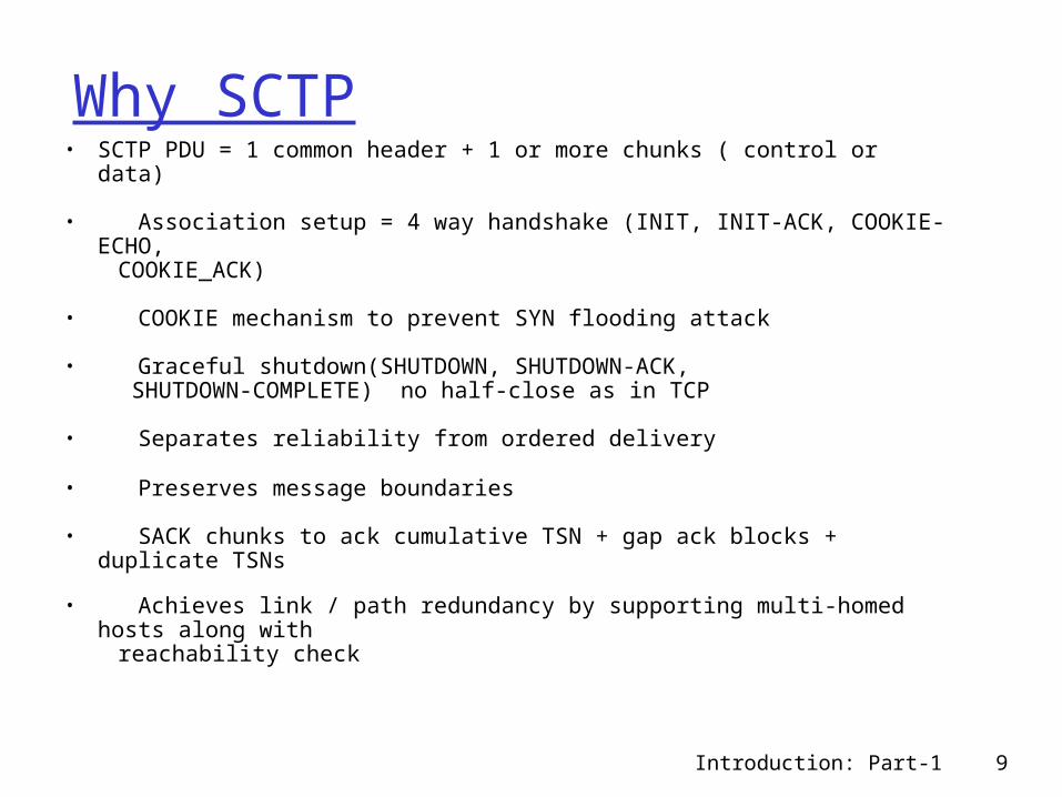
Why SCTP• SCTP PDU = 1 common header + 1 or more chunks ( control or data)
• Association setup = 4 way handshake (INIT, INIT-ACK, COOKIE-ECHO,
COOKIE_ACK)
• COOKIE mechanism to prevent SYN flooding attack
• Graceful shutdown(SHUTDOWN, SHUTDOWN-ACK, SHUTDOWN-COMPLETE) no half-close as in TCP
• Separates reliability from ordered delivery
• Preserves message boundaries
• SACK chunks to ack cumulative TSN + gap ack blocks + duplicate TSNs
• Achieves link / path redundancy by supporting multi-homed hosts along with
reachability check
Introduction: Part-1 10
Forces
Forwarding and Control separation Scalability Interoperability between network
processors Managing Middleboxes
Introduction: Part-1 11
Voice Over IP
lower costs per call, especially for long-distance calls lower infrastructure costs: once IP infrastructure is
installed, no or little additional telephony infrastructure is needed. Note that voice over IP traffic does not necessarily have to travel over the public Internet: it may also be deployed on private IP networks.
End user can manage services Setup and rerouting Voice and data convergence Maintainability
Introduction: Part-1 12
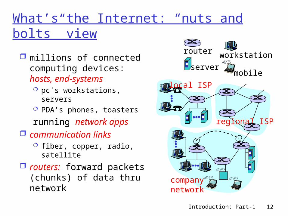
What’s the Internet: “nuts and bolts” view
millions of connected computing devices: hosts, end-systems pc’s workstations, servers PDA’s phones, toasters
running network apps communication links
fiber, copper, radio, satellite
routers: forward packets (chunks) of data thru network
local ISP
companynetwork
regional ISP
router workstation
servermobile
Introduction: Part-1 13
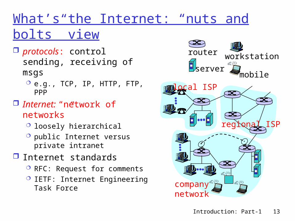
What’s the Internet: “nuts and bolts” view protocols: control sending,
receiving of msgs e.g., TCP, IP, HTTP, FTP, PPP
Internet: “network of networks” loosely hierarchical public Internet versus private
intranet
Internet standards RFC: Request for comments IETF: Internet Engineering
Task Force
local ISP
companynetwork
regional ISP
router workstation
servermobile
Introduction: Part-1 14
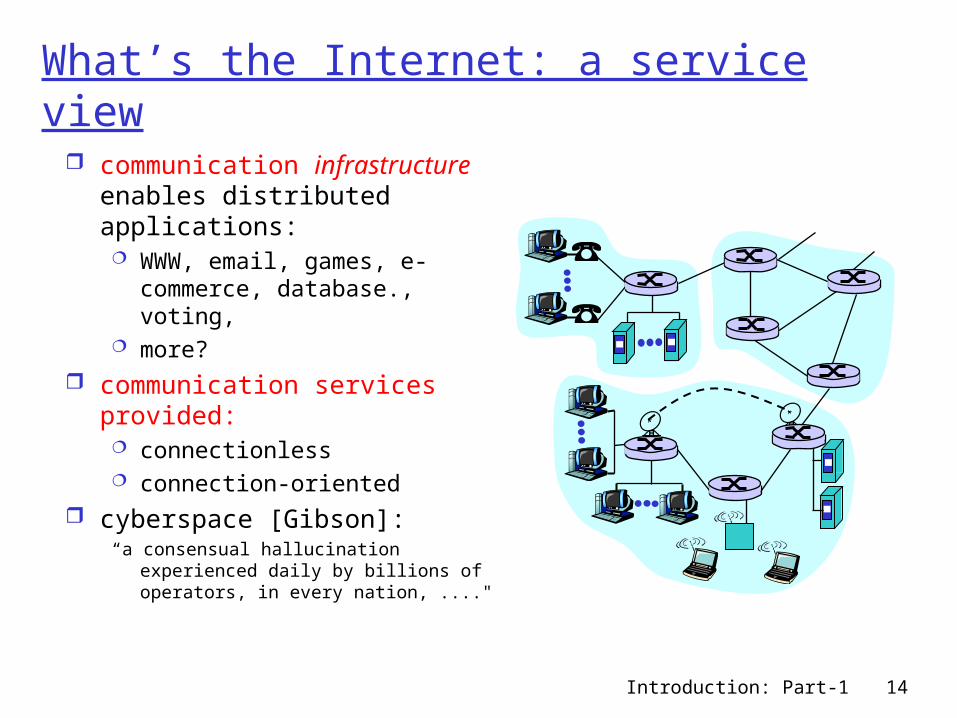
What’s the Internet: a service view
communication infrastructure enables distributed applications: WWW, email, games, e-
commerce, database., voting,
more? communication services
provided: connectionless connection-oriented
cyberspace [Gibson]:“a consensual hallucination experienced
daily by billions of operators, in every nation, ...."
Introduction: Part-1 15
Perspective
Network users: Does the network support the users’ applications Reliability Error free service Speed of data transfer
Network designers: Cost efficient network design Good utilization of network resources Cost of building the network Types of services to be supported Security
Introduction: Part-1 16
Perspective
Network providers: Network administration and customer service Maximize Revenue Minimize Operations Expenses Survivability and Resiliency (Why)
• Discuss the difference!• Give examples
Introduction: Part-1 17
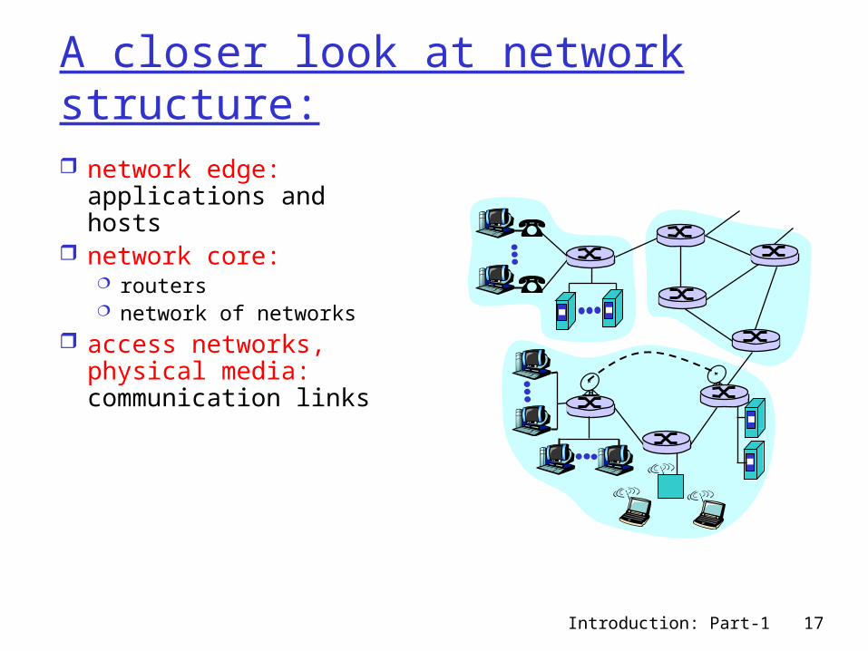
A closer look at network structure: network edge:
applications and hosts network core:
routers network of networks
access networks, physical media: communication links
Introduction: Part-1 18
Building Blocks
Switches, Routers, Gateways Special network components responsible for
“moving” packets across the network from source to destination.
Network hosts, workstations, etc. they generally represent the source and sink
(destination) of data traffic (packets)
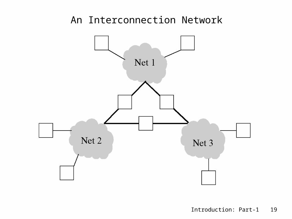
We can recursively build large networks by interconnecting networks via gateways and routers.
Introduction: Part-1 19
An Interconnection Network
Introduction: Part-1 20
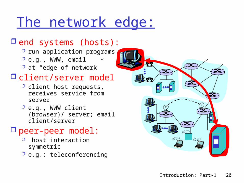
The network edge: end systems (hosts):
run application programs e.g., WWW, email at “edge of network”
client/server model client host requests,
receives service from server
e.g., WWW client (browser)/ server; email client/server
peer-peer model: host interaction symmetric e.g.: teleconferencing
Introduction: Part-1 21
Network edge: connection-oriented service
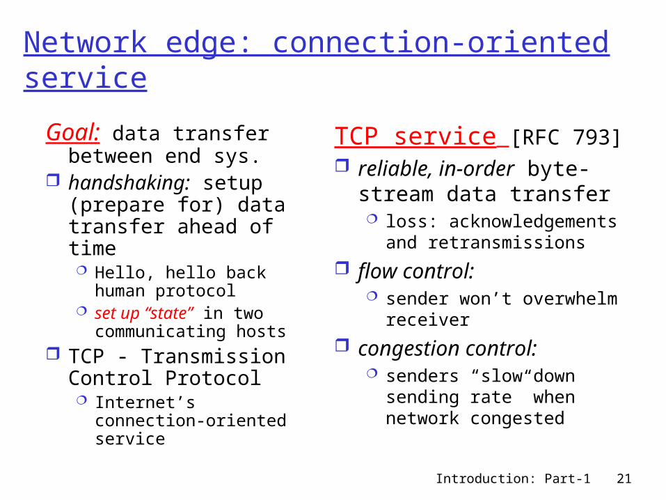
Goal: data transfer between end sys.
handshaking: setup (prepare for) data transfer ahead of time Hello, hello back
human protocol set up “state” in two
communicating hosts TCP - Transmission
Control Protocol Internet’s connection-
oriented service
TCP service [RFC 793] reliable, in-order byte-
stream data transfer loss: acknowledgements
and retransmissions
flow control: sender won’t overwhelm
receiver
congestion control: senders “slow down
sending rate” when network congested
Introduction: Part-1 22
Network edge: connectionless service
Goal: data transfer between end systems same as before!
UDP - User Datagram Protocol [RFC 768]: Internet’s connectionless service unreliable data
transfer no flow control no congestion
control
App’s using TCP: HTTP (WWW), FTP
(file transfer), Telnet (remote login), SMTP (email)
App’s using UDP: streaming media,
teleconferencing, Internet telephony
Introduction: Part-1 23
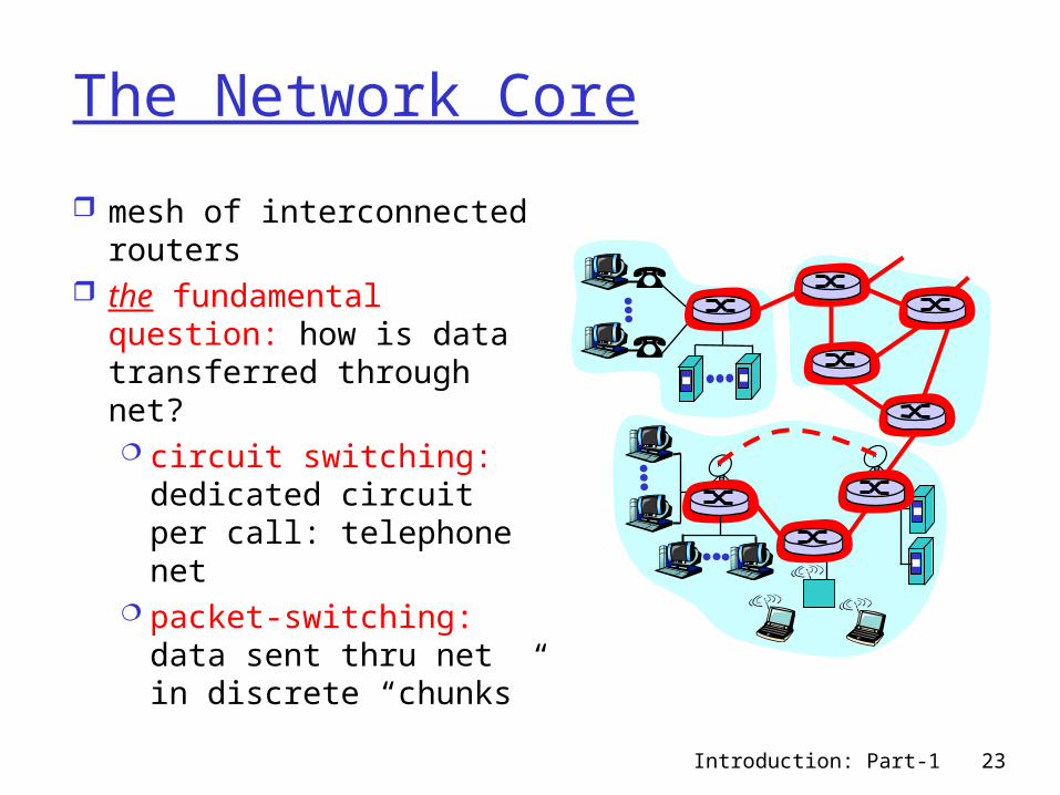
The Network Core
mesh of interconnected routers
the fundamental question: how is data transferred through net? circuit switching:
dedicated circuit per call: telephone net
packet-switching: data sent thru net in discrete “chunks”

Introduction: Part-1 24
Different Types of Switching
Different Types of Switching: Circuit Switching (telephone network)
• dedicated circuit, sending and receiving bit streams
Message Switching Packet Switching
• store and forward, sending and receiving packets Virtual Circuit Switching Cell Switching (ATM)
What are Packets? Data to be transmitted is divided into
discrete blocks
Introduction: Part-1 25
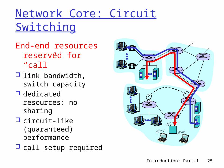
Network Core: Circuit Switching
End-end resources reserved for “call”
link bandwidth, switch capacity
dedicated resources: no sharing
circuit-like (guaranteed) performance
call setup required
Introduction: Part-1 26
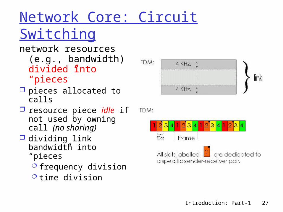
Cost-Effective Resource Sharing Must share (multiplex) network
resources among multiple users.
Common Multiplexing Strategies Time-Division Multiplexing (TDM) Synchronous TDM (STDM) Frequency-Division Multiplexing (FDM)
Multiplexing multiple logical flows over a single physical link.
Introduction: Part-1 27
Network Core: Circuit Switching
network resources (e.g., bandwidth) divided into “pieces”
pieces allocated to calls resource piece idle if not
used by owning call (no sharing)
dividing link bandwidth into “pieces” frequency division time division
Introduction: Part-1 28
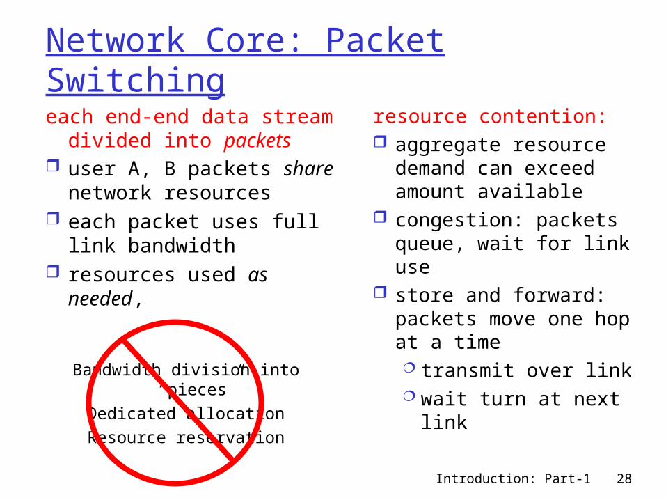
Network Core: Packet Switching
each end-end data stream divided into packets
user A, B packets share network resources
each packet uses full link bandwidth
resources used as needed,
resource contention: aggregate resource
demand can exceed amount available
congestion: packets queue, wait for link use
store and forward: packets move one hop at a time transmit over link wait turn at next
link
Bandwidth division into “pieces”Dedicated allocationResource reservation
Introduction: Part-1 29
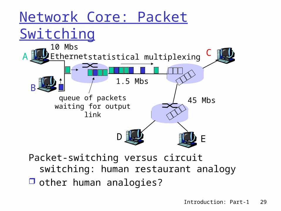
Network Core: Packet Switching
Packet-switching versus circuit switching: human restaurant analogy
other human analogies?
A
B
C10 MbsEthernet
1.5 Mbs
45 Mbs
D E
statistical multiplexing
queue of packetswaiting for output
link
Introduction: Part-1 30
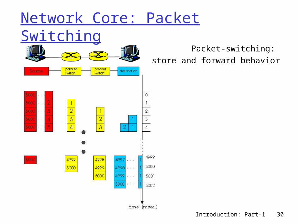
Network Core: Packet SwitchingPacket-switching:
store and forward behavior
Introduction: Part-1 31
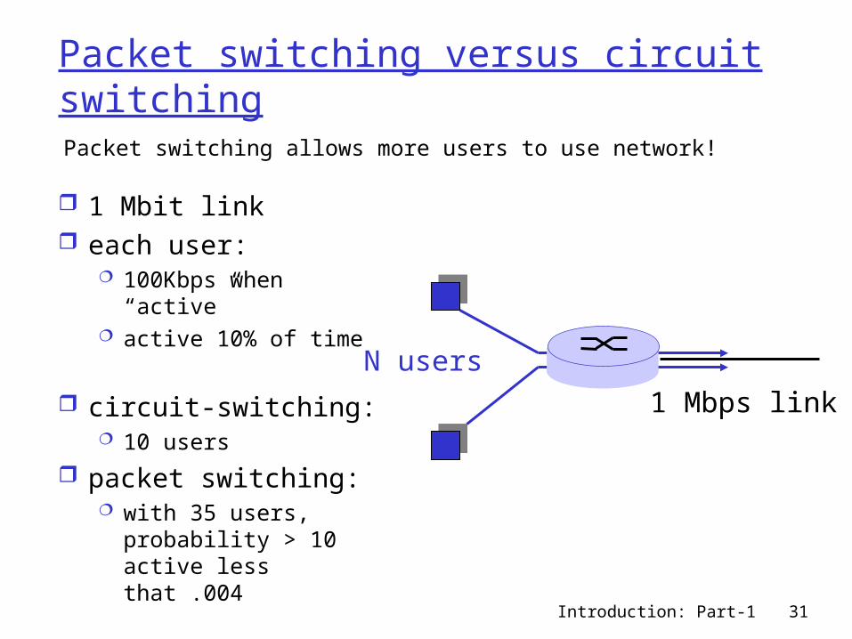
Packet switching versus circuit switching
1 Mbit link each user:
100Kbps when “active”
active 10% of time
circuit-switching: 10 users
packet switching: with 35 users,
probability > 10 active less that .004
Packet switching allows more users to use network!
N users
1 Mbps link
Introduction: Part-1 32
Packet switching versus circuit switching
Great for bursty data resource sharing no call setup
Excessive congestion: packet delay and loss protocols needed for reliable data transfer,
congestion control Q: How to provide circuit-like behavior?
bandwidth guarantees needed for audio/video apps
still an unsolved problem (chapter 6)
Is packet switching a “slam dunk winner?”
Introduction: Part-1 33
Packet-switched networks: routing
Goal: move packets among routers from source to destination we’ll study several path selection algorithms (chapter
4) datagram network:
destination address determines next hop routes may change during session analogy: driving, asking directions
virtual circuit network: each packet carries tag (virtual circuit ID), tag
determines next hop fixed path determined at call setup time, remains fixed
thru call routers maintain per-call state
Introduction: Part-1 34
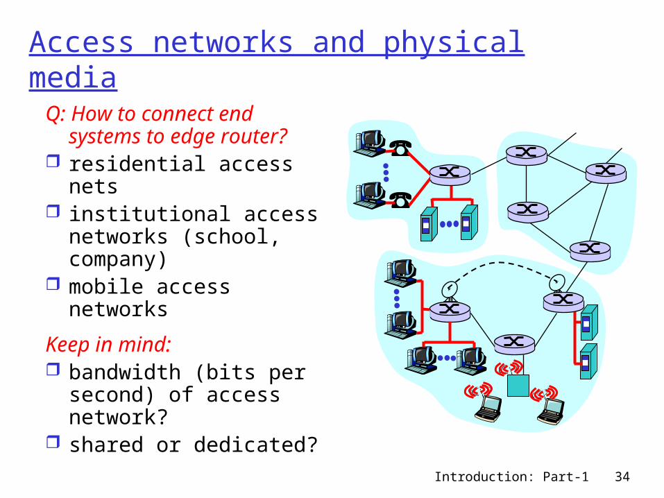
Access networks and physical media
Q: How to connect end systems to edge router?
residential access nets institutional access
networks (school, company)
mobile access networks
Keep in mind: bandwidth (bits per
second) of access network?
shared or dedicated?
Introduction: Part-1 35
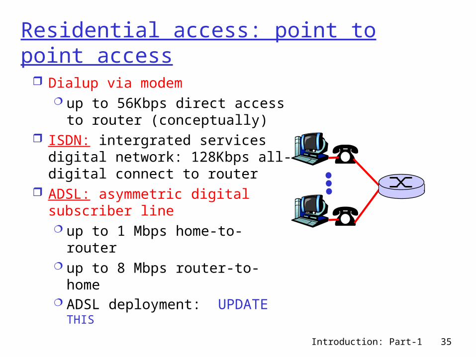
Residential access: point to point access
Dialup via modem up to 56Kbps direct access to
router (conceptually) ISDN: intergrated services
digital network: 128Kbps all-digital connect to router
ADSL: asymmetric digital subscriber line up to 1 Mbps home-to-router up to 8 Mbps router-to-home ADSL deployment: UPDATE
THIS
Introduction: Part-1 36
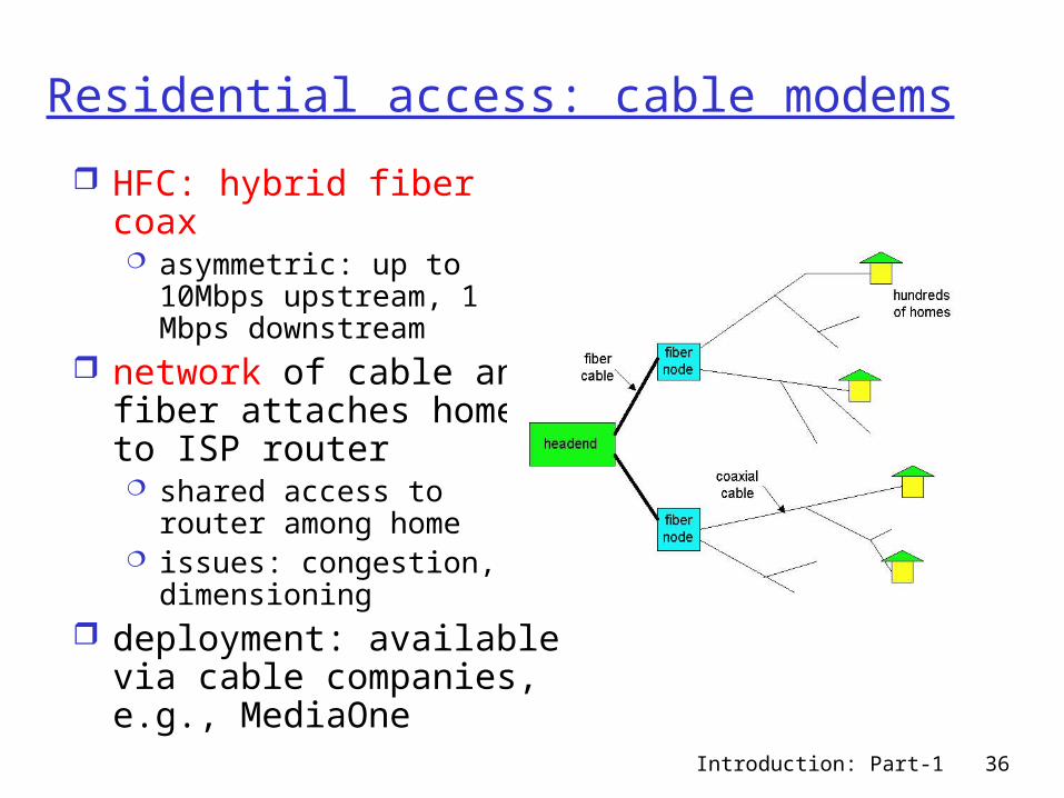
Residential access: cable modems
HFC: hybrid fiber coax asymmetric: up to 10Mbps
upstream, 1 Mbps downstream
network of cable and fiber attaches homes to ISP router shared access to router
among home issues: congestion,
dimensioning deployment: available
via cable companies, e.g., MediaOne
Introduction: Part-1 37
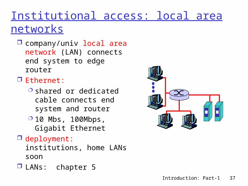
Institutional access: local area networks
company/univ local area network (LAN) connects end system to edge router
Ethernet: shared or dedicated
cable connects end system and router
10 Mbs, 100Mbps, Gigabit Ethernet
deployment: institutions, home LANs soon
LANs: chapter 5
Introduction: Part-1 38
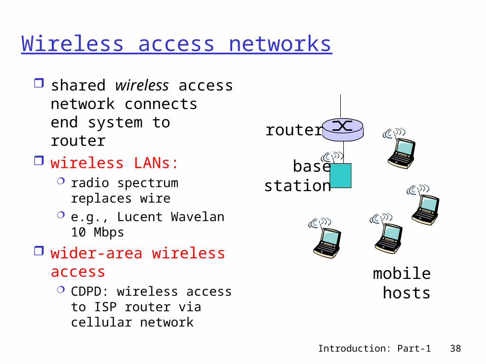
Wireless access networks
shared wireless access network connects end system to router
wireless LANs: radio spectrum replaces
wire e.g., Lucent Wavelan 10
Mbps
wider-area wireless access CDPD: wireless access
to ISP router via cellular network
basestation
mobilehosts
router
Introduction: Part-1 39
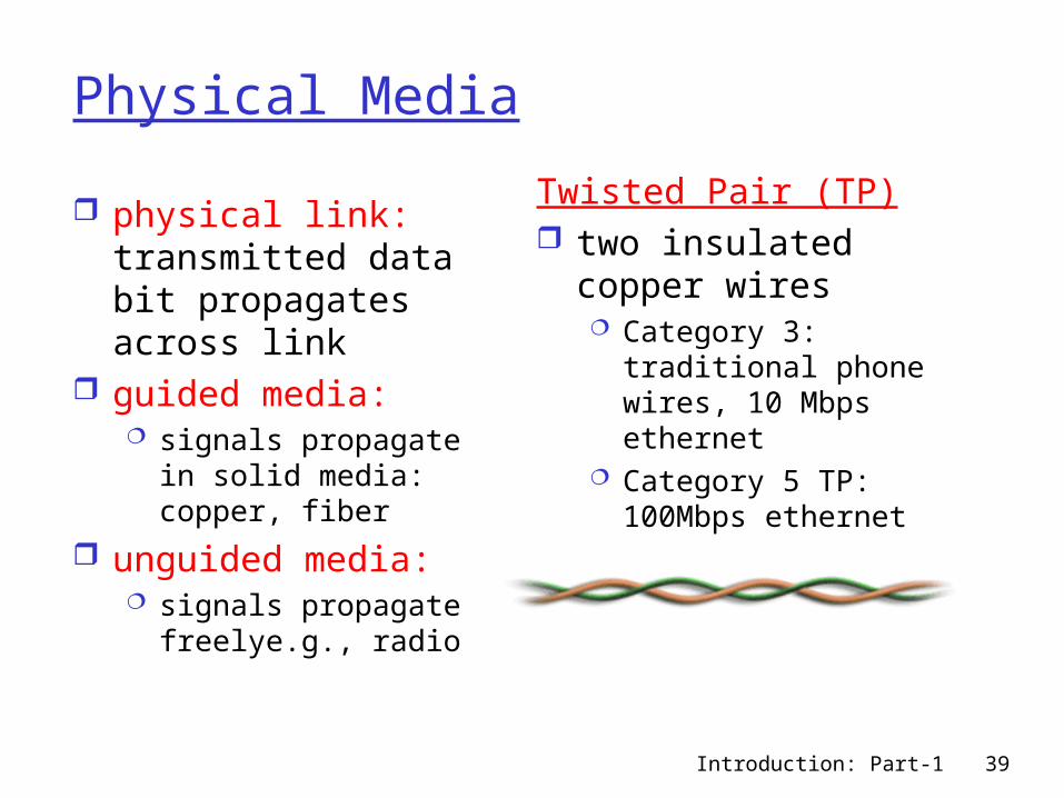
Physical Media
physical link: transmitted data bit propagates across link
guided media: signals propagate in
solid media: copper, fiber
unguided media: signals propagate
freelye.g., radio
Twisted Pair (TP) two insulated copper
wires Category 3: traditional
phone wires, 10 Mbps ethernet
Category 5 TP: 100Mbps ethernet
Introduction: Part-1 40
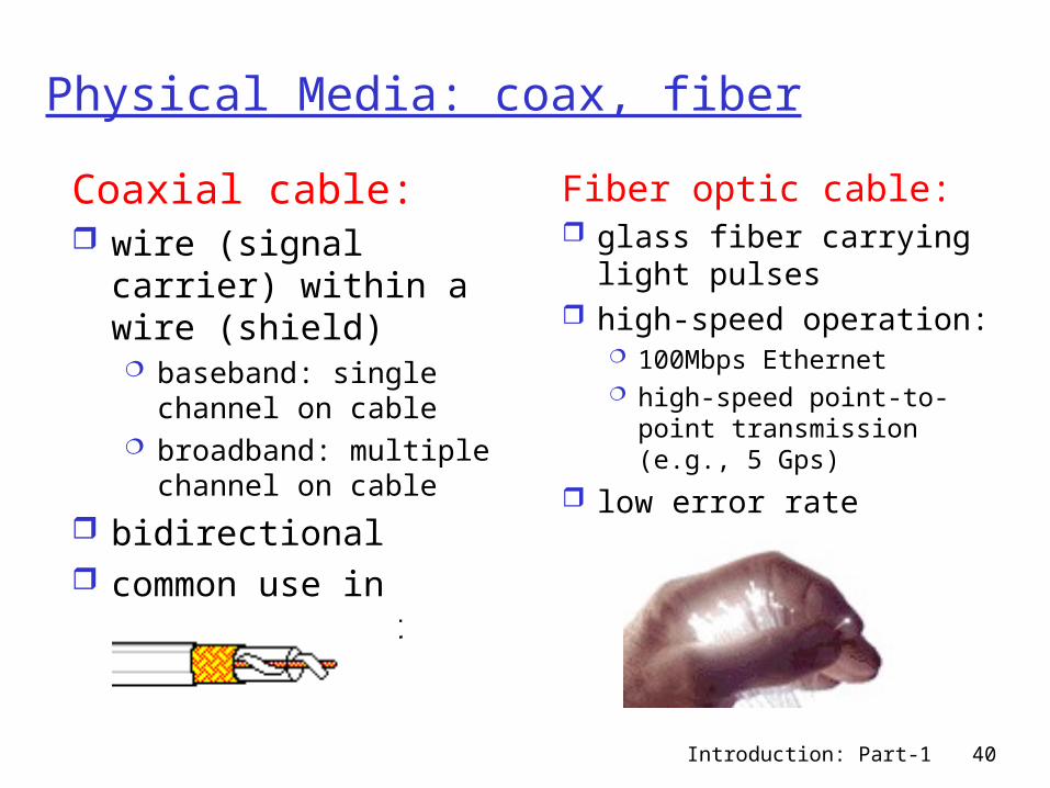
Physical Media: coax, fiber
Coaxial cable: wire (signal carrier)
within a wire (shield) baseband: single
channel on cable broadband: multiple
channel on cable
bidirectional common use in
10Mbs Ethernet
Fiber optic cable: glass fiber carrying
light pulses high-speed operation:
100Mbps Ethernet high-speed point-to-
point transmission (e.g., 5 Gps)
low error rate
Introduction: Part-1 41
Physical media: radio
signal carried in electromagnetic spectrum
no physical “wire” bidirectional propagation
environment effects: reflection obstruction by objects interference
Radio link types: microwave
e.g. up to 45 Mbps channels
LAN (e.g., waveLAN) 2Mbps, 11Mbps
wide-area (e.g., cellular) e.g. CDPD, 10’s Kbps
satellite up to 50Mbps channel (or multiple
smaller channels) 270 Msec end-end delay geosynchronous versus LEOS
Introduction: Part-1 42
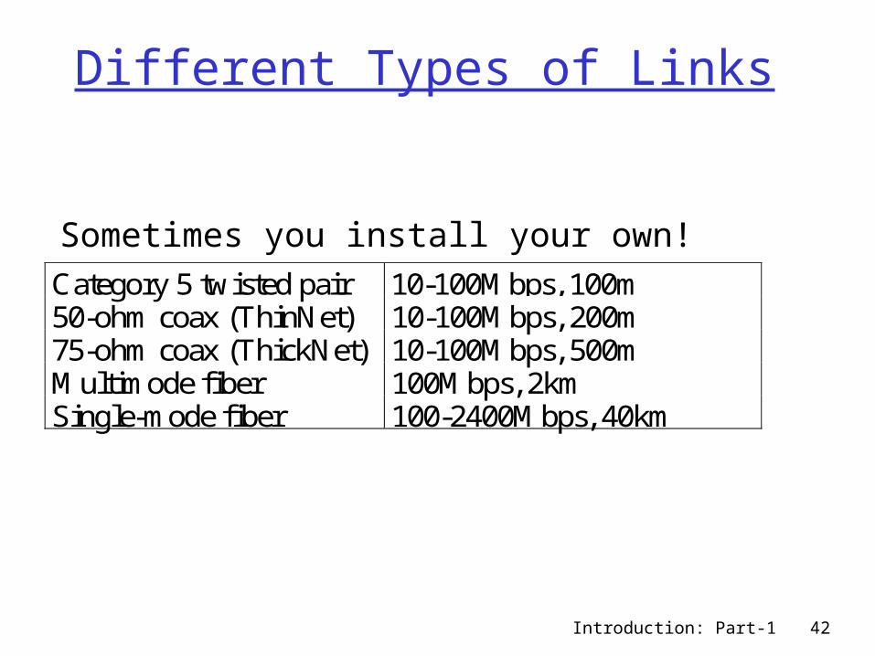
Different Types of Links
Sometimes you install your own!Category 5 twisted pair 10-100Mbps, 100m50-ohm coax (ThinNet) 10-100Mbps, 200m75-ohm coax (ThickNet) 10-100Mbps, 500mMultimode fiber 100Mbps, 2kmSingle-mode fiber 100-2400Mbps, 40km
Introduction: Part-1 43
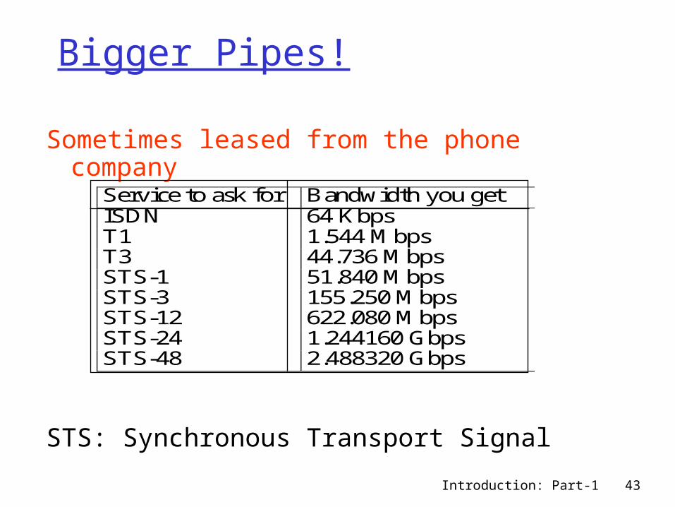
Bigger Pipes!
Sometimes leased from the phone company
STS: Synchronous Transport Signal
Service to ask for Bandwidth you getISDN 64 KbpsT1 1.544 MbpsT3 44.736 MbpsSTS-1 51.840 MbpsSTS-3 155.250 MbpsSTS-12 622.080 MbpsSTS-24 1.244160 GbpsSTS-48 2.488320 Gbps
Introduction: Part-1 44
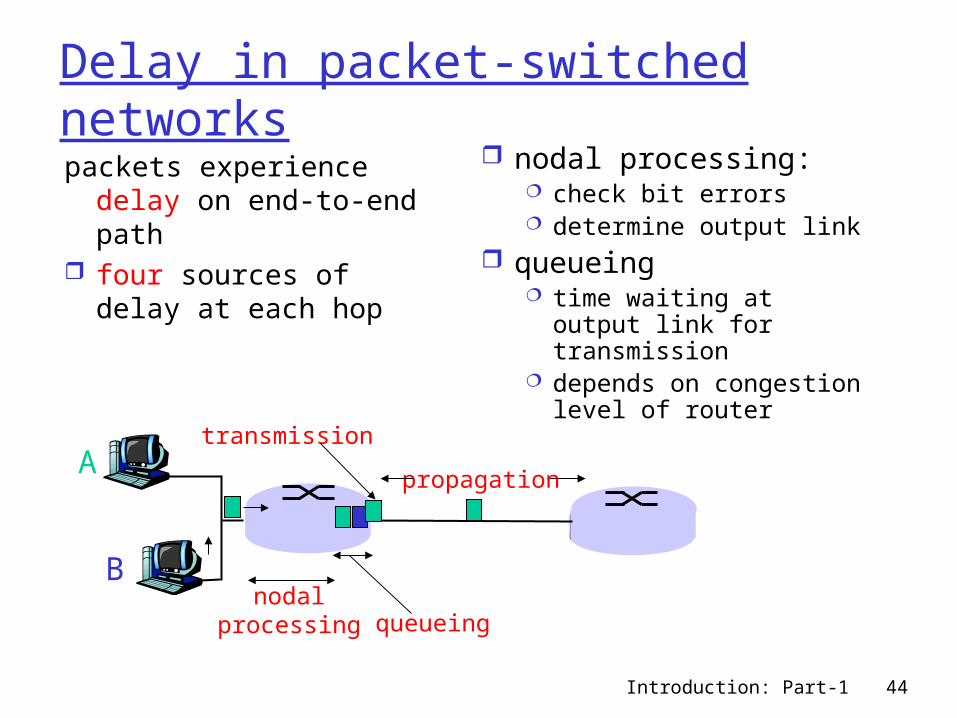
Delay in packet-switched networkspackets experience delay
on end-to-end path four sources of delay at
each hop
nodal processing: check bit errors determine output link
queueing time waiting at output
link for transmission depends on
congestion level of router
A
B
propagation
transmission
nodalprocessing queueing
Introduction: Part-1 45
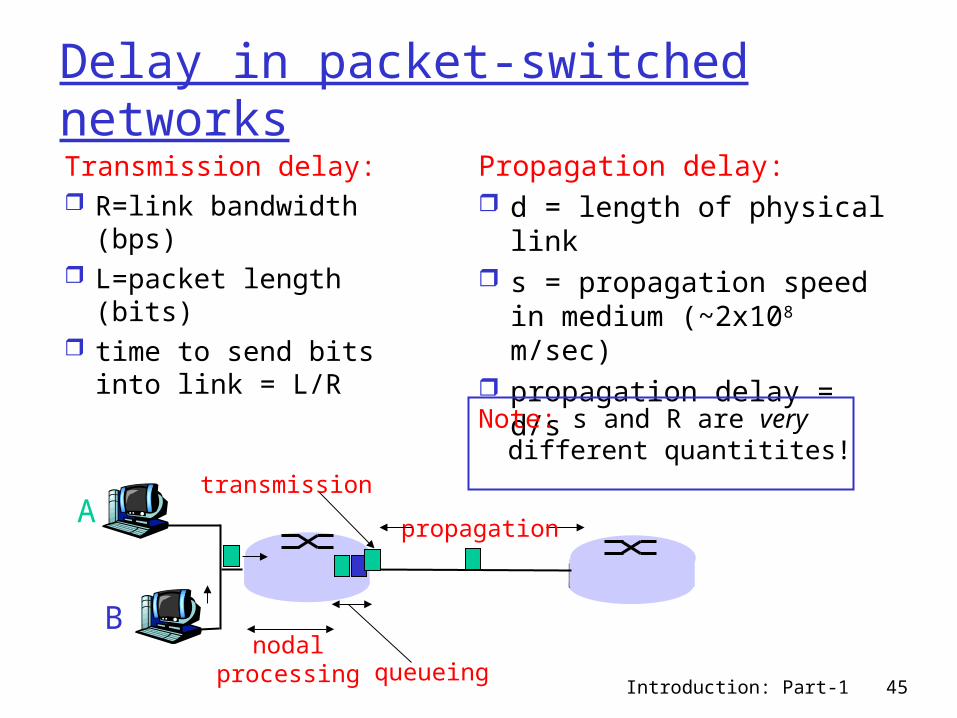
Delay in packet-switched networksTransmission delay: R=link bandwidth
(bps) L=packet length (bits) time to send bits into
link = L/R
Propagation delay: d = length of physical
link s = propagation speed in
medium (~2x10⁸ m/sec) propagation delay = d/s
A
B
propagation
transmission
nodalprocessing queueing
Note: s and R are very different quantitites!
Introduction: Part-1 46
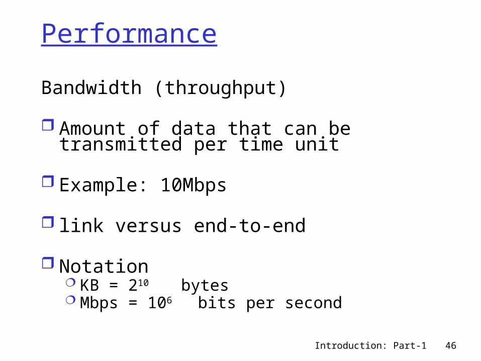
Bandwidth (throughput)
Amount of data that can be transmitted per time unit
Example: 10Mbps
link versus end-to-end
Notation KB = 210 bytes Mbps = 106 bits per second
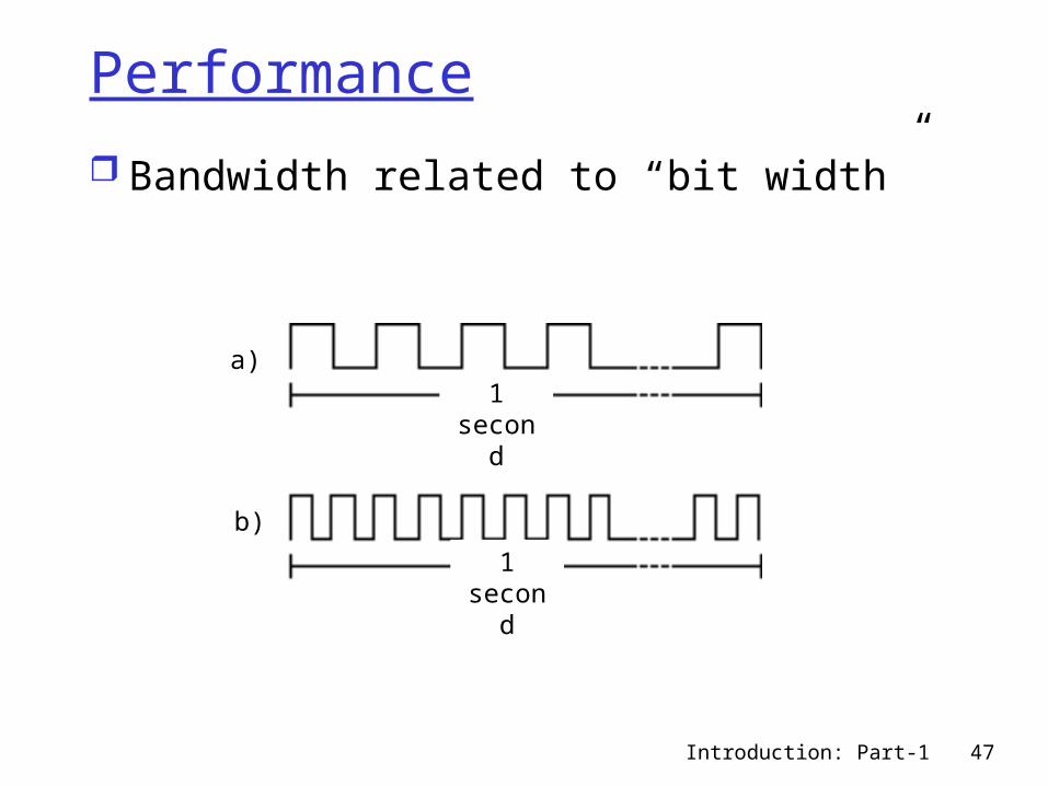
Performance
Introduction: Part-1 47
Bandwidth related to “bit width”
Performance
a)
b)
1 second
1 second
Introduction: Part-1 48
Latency (delay) Time it takes to send message from
point A to point B Example: 24 milliseconds (ms) Sometimes interested in in round-trip
time (RTT) Components of latency
Latency = Propagation + Transmit + Queue + Proc.
Propagation = Distance / SpeedOfLight
Transmit = Size / Bandwidth
Introduction: Part-1 49
The “hard” limit
Speed of light 3.0 x 10⁸ meters/second in a vacuum 2.3 x 10⁸ meters/second in a cable 2.0 x 10⁸ meters/second in a fiber
Notes no queuing delays in direct link bandwidth not relevant if Size = 1 bit process-to-process latency includes
software overhead software overhead can dominate when
Distance is small
Introduction: Part-1 50
Relative importance of bandwidth and latency small message (e.g., 1 byte): 1ms vs. 100ms
dominates 1Mbps vs. 100Mbps large message (e.g., 25 MB): 1Mbps vs.
100Mbps dominates 1ms vs. 100ms
Consider two channels of 1Mbps and 100 Mbps respectively. For a 1 byte message, the available bandwidth is relatively insignificant given a RTT of 1 ms. The transmit delay for each channel is 8 s and 0.08 s, respectively.
Introduction: Part-1 51
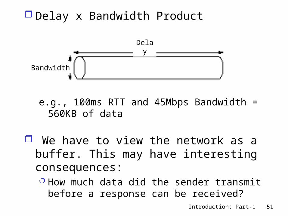
Delay x Bandwidth Product
e.g., 100ms RTT and 45Mbps Bandwidth = 560KB of data
We have to view the network as a buffer. This may have interesting consequences: How much data did the sender transmit
before a response can be received?
Bandwidth
Delay
Introduction: Part-1 52
Application Needs bandwidth requirements: burst versus peak
rate jitter: variance in latency (inter-packet gap)
Average Bandwidth Requirement is Not enough: consider a source with an avg. BW-
requirement of 2Mbps. If the application generates 1 Mbit in one second interval and 3Mbit in a second, a channel that can support 2 Mbps max. will have a tough time.
Other Quality of Service (QOS) Parameters: max. and min. delay max. and min. bandwidth demand rates for dynamic increase of demands Cell-Loss Rate
Introduction: Part-1 53
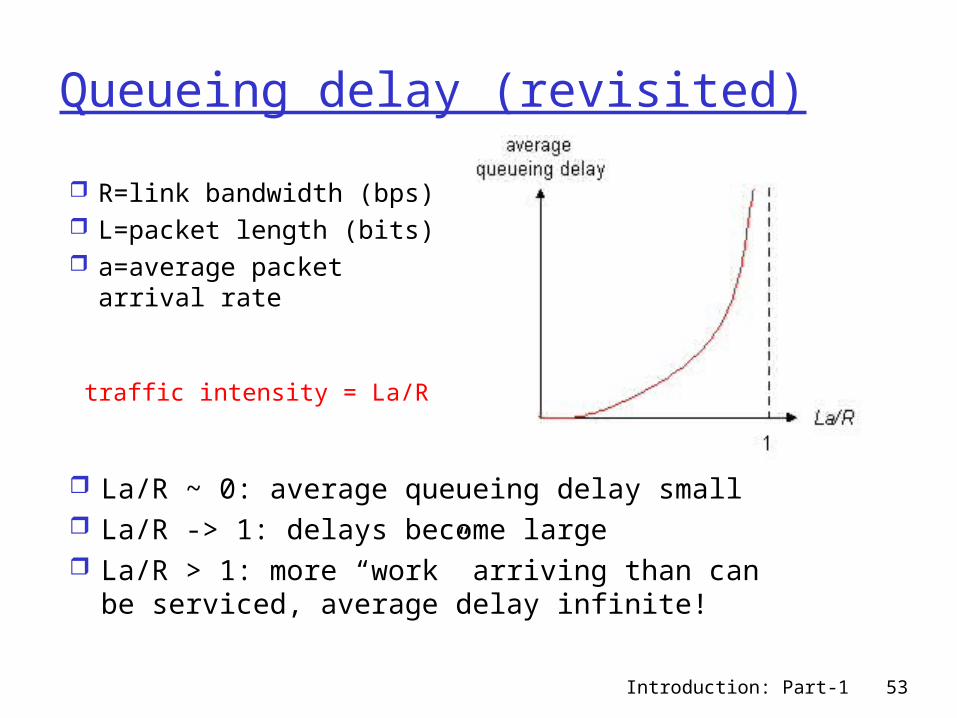
Queueing delay (revisited)
R=link bandwidth (bps) L=packet length (bits) a=average packet
arrival rate
traffic intensity = La/R
La/R ~ 0: average queueing delay small La/R -> 1: delays become large La/R > 1: more “work” arriving than can
be serviced, average delay infinite!
Introduction: Part-1 54
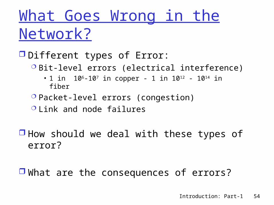
What Goes Wrong in the Network? Different types of Error:
Bit-level errors (electrical interference)• 1 in 106-107 in copper - 1 in 1012 - 1014 in fiber
Packet-level errors (congestion) Link and node failures
How should we deal with these types of error?
What are the consequences of errors?
Introduction: Part-1 55
Other types of problems in the Network?
Messages are delayed Messages are deliver out-of-order Third parties eavesdrop
The key problem is to fill in the gap between what applications expect and what the underlying technology provides.