Embed Size (px)
Citation preview
Rochester Air Center
Introduction
To maximize the effectiveness of your flight program, RAC’s Piper Seneca Training Supplement contains a condensed overview of multi-engine aerodynamics, portions of the Piper Seneca POH, and flight procedures. You must have a complete knowledge of all information contained in this supplement prior to the start of your program. This information will assist you with your training and flight check.
It is critical that you memorize the following:
• Emergency Engine Failure Checklists. • V-Speeds. • Answers to all questions contained in the “Oral Review”
section in the back of the supplement.
The information in this supplement is highly condensed and serves as a good quick reference, but it must not be used as a substitute for the FAA-approved pilot's operating handbook required for safe operation of the airplane.
Rochester Air Center
Contents Version (21 January 2012)
Engine-Out Aerodynamics.............1 Aerodynamic Effects of an Engine Failure .. 1 Approximate Drag Factors .......................... 2 Airspeeds for Max SE Performance............. 2 Sideslip Versus Zero Sideslip ...................... 3 Single-Engine Service Ceiling ...................... 4 Single-Engine Absolute Ceiling .................... 4 Climb Performance Factors ......................... 4 Critical Engine.............................................. 4 VMC ....................................................................... 6
Aircraft Systems .............................8 Engines........................................................ 8 Oil System………………………………….9 Turbo Chargers……………...………...10 Fuel Injection …………………………………14 Propellers..................................................16 Landing Gear ............................................. 19 Brakes ....................................................... 20 Flight Controls…………………………………………..20 Flaps.......................................................... 21 Vacuum Pumps.......................................... 21 Pitot Static ................................................. 21 Fuel System ............................................... 22 Electrical System ....................................... 22 Heater ....................................................... 23 Stall Warning Horn..................................... 24 Ice Protection System…………………24 Pressurization System (CMEL/ATP)….25 Inoperative Instruments and Equipment... 31
Performance / Weight & Balance32 Piper Seneca II V-Speeds .......................... 32 Takeoff Landing Card………………………….….33
Oral Review................................. 38
Engine-Out Aerodynamics • 1
Rochester Air Center
SECTION 1
Engine-Out Aerodynamics
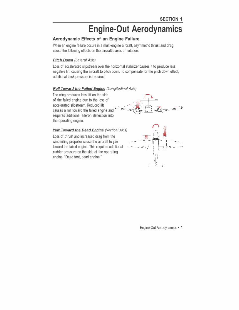
Aerodynamic Effects of an Engine Failure When an engine failure occurs in a multi-engine aircraft, asymmetric thrust and drag cause the following effects on the aircraft’s axes of rotation:
Pitch Down (Lateral Axis) Loss of accelerated slipstream over the horizontal stabilizer causes it to produce less negative lift, causing the aircraft to pitch down. To compensate for the pitch down effect, additional back pressure is required.
Roll Toward the Failed Engine (Longitudinal Axis) The wing produces less lift on the side of the failed engine due to the loss of accelerated slipstream. Reduced lift causes a roll toward the failed engine and requires additional aileron deflection into the operating engine.
Yaw Toward the Dead Engine (Vertical Axis) Loss of thrust and increased drag from the windmilling propeller cause the aircraft to yaw toward the failed engine. This requires additional rudder pressure on the side of the operating engine. “Dead foot, dead engine.”
2 • Engine-Out Aerodynamics
Rochester Air Center
Engine Inoperative Climb Performance Climb performance depends on the excess power needed to overcome drag. When a multi- engine airplane loses an engine, the airplane loses 50% of its available power. This power loss results in a loss of approximately 80% of the aircraft’s excess power and climb performance. Drag is a major factor relative to the amount of excess power available. An increase in drag (such as the loss of one engine) must be offset by additional power. This additional power is now taken from the excess power, making it unavailable to aid the aircraft in climb. When an engine is lost, maximize thrust (full power) and minimize drag (flaps and gear up, prop feathered, etc.) in order to achieve optimum single-engine climb performance.
Approximate Drag Factors for the Piper Seneca
1. Flaps 25˚ -240 FPM 2. Flaps 40˚ -275 FPM 3. Windmilling Prop -200 FPM 4. Gear Extended -250 FPM
Under FAR Part 23: The FAA does not require multi-engine airplanes that weigh less than 6000 pounds or have a VSO speed under 61 knots to meet any specified single-engine performance criteria. No single engine climb performance is required. Actual climb performance is documented by the manufacturer.
The Seneca’s maximum takeoff weight is 4570 lbs. and Vso is 61 KIAS. Review the POH for single engine climb performance under specific conditions.
Airspeeds for Max Single-Engine Performance
VXSE
The airspeed for the steepest angle of climb on single-engine. (78 KIAS in the Seneca).
VYSE
The airspeed for the best rate of climb on single-engine. (Or for the slowest loss of altitude on drift-down.) Blueline is the marking on the airspeed indicator corresponding to VYSE at max weight. (89 KIAS in the Seneca).
Engine-Out Aerodynamics • 3
Rochester Air Center
Sideslip Versus Zero Sideslip During flight with one engine inoperative, proper pilot technique is required to maximize aircraft performance. An impor tant technique is to establish a Zero Sideslip Condition.
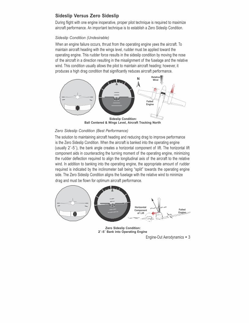
Sideslip Condition (Undesirable) When an engine failure occurs, thrust from the operating engine yaws the aircraft. To maintain aircraft heading with the wings level, rudder must be applied toward the operating engine. This rudder force results in the sideslip condition by moving the nose of the aircraft in a direction resulting in the misalignment of the fuselage and the relative wind. This condition usually allows the pilot to maintain aircraft heading; however, it produces a high drag condition that significantly reduces aircraft performance.
Relative Wind
Failed Engine
Sideslip Condition: Ball Centered & Wings Level, Aircraft Tracking North
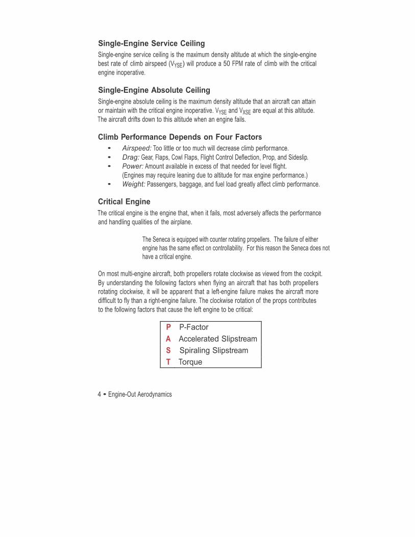
Zero Sideslip Condition (Best Performance) The solution to maintaining aircraft heading and reducing drag to improve performance is the Zero Sideslip Condition. When the aircraft is banked into the operating engine (usually 2˚-5˚), the bank angle creates a horizontal component of lift. The horizontal lift component aids in counteracting the turning moment of the operating engine, minimizing the rudder deflection required to align the longitudinal axis of the aircraft to the relative wind. In addition to banking into the operating engine, the appropriate amount of rudder required is indicated by the inclinometer ball being “split” towards the operating engine side. The Zero Sideslip Condition aligns the fuselage with the relative wind to minimize drag and must be flown for optimum aircraft performance.
Horizontal Component
of Lift Failed Engine
Zero Sideslip Condition: 2˚-5˚ Bank into Operating Engine
4 • Engine-Out Aerodynamics
Rochester Air Center
Single-Engine Service Ceiling Single-engine service ceiling is the maximum density altitude at which the single-engine best rate of climb airspeed (VYSE) will produce a 50 FPM rate of climb with the critical engine inoperative.
Single-Engine Absolute Ceiling Single-engine absolute ceiling is the maximum density altitude that an aircraft can attain or maintain with the critical engine inoperative. VYSE and VXSE are equal at this altitude. The aircraft drifts down to this altitude when an engine fails.
Climb Performance Depends on Four Factors
• Airspeed: Too little or too much will decrease climb performance. • Drag: Gear, Flaps, Cowl Flaps, Flight Control Deflection, Prop, and Sideslip. • Power: Amount available in excess of that needed for level flight.
(Engines may require leaning due to altitude for max engine performance.) • Weight: Passengers, baggage, and fuel load greatly affect climb performance.
Critical Engine The critical engine is the engine that, when it fails, most adversely affects the performance and handling qualities of the airplane.
The Seneca is equipped with counter rotating propellers. The failure of either engine has the same effect on controllability. For this reason the Seneca does not have a critical engine.
On most multi-engine aircraft, both propellers rotate clockwise as viewed from the cockpit. By understanding the following factors when flying an aircraft that has both propellers rotating clockwise, it will be apparent that a left-engine failure makes the aircraft more difficult to fly than a right-engine failure. The clockwise rotation of the props contributes to the following factors that cause the left engine to be critical:
P P-Factor A Accelerated Slipstream S Spiraling Slipstream T Torque
Engine-Out Aerodynamics • 5
Rochester Air Center
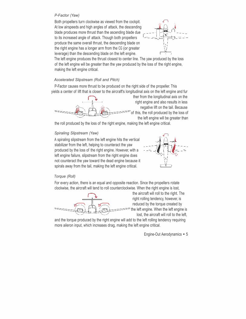
P-Factor (Yaw) Both propellers turn clockwise as viewed from the cockpit. At low airspeeds and high angles of attack, the descending blade produces more thrust than the ascending blade due to its increased angle of attack. Though both propellers produce the same overall thrust, the descending blade on the right engine has a longer arm from the CG (or greater leverage) than the descending blade on the left engine. The left engine produces the thrust closest to center line. The yaw produced by the loss of the left engine will be greater than the yaw produced by the loss of the right engine, making the left engine critical.
Accelerated Slipstream (Roll and Pitch) P-Factor causes more thrust to be produced on the right side of the propeller. This
yields a center of lift that is closer to the aircraft's longitudinal axis on the left engine and fur ther from the longitudinal axis on the
right engine and also results in less negative lift on the tail. Because
of this, the roll produced by the loss of the left engine will be greater than
the roll produced by the loss of the right engine, making the left engine critical.
Spiraling Slipstream (Yaw) A spiraling slipstream from the left engine hits the ver tical stabilizer from the left, helping to counteract the yaw produced by the loss of the right engine. However, with a left engine failure, slipstream from the right engine does not counteract the yaw toward the dead engine because it spirals away from the tail, making the left engine critical.
Torque (Roll) For every action, there is an equal and opposite reaction. Since the propellers rotate clockwise, the aircraft will tend to roll counterclockwise. When the right engine is lost,
the aircraft will roll to the right. The right rolling tendency, however, is reduced by the torque created by
the left engine. When the left engine is lost, the aircraft will roll to the left,
and the torque produced by the right engine will add to the left rolling tendency requiring more aileron input, which increases drag, making the left engine critical.
6 • Engine-Out Aerodynamics
Rochester Air Center
Summary On most light multi-engine aircraft when the critical engine is inoperative, both directional control and performance suffer more than when the non-critical engine is inoperative.
VMC VMC is the minimum airspeed at which directional control can be maintained with the critical engine inoperative. VMC speed is marked on the airspeed indicator by a red radial line. Aircraft manufacturers determine VMC speed based on conditions set by the FAA under FAR §23.149:
1. Most Unfavorable Weight and Center of Gravity 2. Standard Day Conditions at Sea Level (Max Engine Power) 3. Maximum Power on the Operating Engine (Max Yaw) 4. Critical Engine Prop Windmilling (Max Drag) 5. Flaps Takeoff Position, Landing Gear Up, Trimmed for Takeoff (Least Stability) 6. Up to 5˚ of Bank into the Operating Engine
The above items are the conditions set by the FAA for determining Vmc during certification. Changes to the above conditions may change VMC, possibly significantly. The following summarizes how VMC may be affected by the above conditions:
1. Most Unfavorable Weight
The cer tification test allows up to 5˚ bank into the operating engine. In a given bank, the heavier the aircraft, the greater the horizontal component of lift that adds to the rudder force. As weight increases, the horizontal component of lift increases, which added to the rudder force, decreases VMC as the rudder does not have to exert as much force to counteract the yawing/turning moment. 2. Center of Gravity As the center of gravity moves forward, the moment arm between the rudder and the CG is lengthened, increasing the leverage of the rudder. This increased leverage increases the rudder’s effectiveness and results in a lower VMC speed. (Arm is defined as the perpendicular distance from the point of rotation to the line of action of the force. Or, in this case, the perpendicular distance from the center of gravity to the rudder).
2. Standard Day Sea Level Standard conditions yield high air density that allows the engine to develop maximum power. An increase in altitude or temperature (a decrease in air density) will result in reduced engine performance and prop efficiency. This decreases the adverse yaw effect. VMC speed
Engine-Out Aerodynamics • 7
Rochester Air Center
decreases as altitude increases.
3. Maximum Power On The Operating Engine When the operating engine develops maximum power, adverse yaw is increased toward the
inoperative engine. The pilot must overcome this yaw to maintain directional control. Any condition that increases power on the operating engine will increase Vmc speed. Any
condition that decreases power on the operating engine (such as power reduction by the pilot, an increase in altitude, temperature, low density, or aging engine) will decrease VMC. Note that the Seneca II has turbo charged engines so this will not affect the aircraft until it reaches the critical altitude- or 12,000 feet.
4. Critical Engine Prop Windmilling When the propeller is in a low pitch position (unfeathered), it presents a large area of resistance to the relative wind. This resistance causes the engine to “windmill.” The windmilling creates a large amount of drag and results in a yawing moment into the dead engine. When the propeller is “feathered,” the blades are in a high pitch position, which aligns them with the relative wind, minimizing drag. A feathered prop will decrease drag and lower VMC.
5. Flaps Takeoff Position, Landing Gear Up, Trimmed for Takeoff As per an FAA letter dated 20 May 2000 landing gear extended may raise, lower or have no effect on Vmc. http://www.boundvortex.com/downloads/Faa%20gear.pdf Extended flaps have a stabilizing effect that may reduce VMC speed.
6. Up to 5˚ Bank into the Operating Engine When the wings are level, only the rudder is used to stop the yaw produced by the operating engine (sideslip condition). Banking into the operating engine creates a horizontal component of lift which aids the rudder force. With this horizontal component of lift and full rudder deflection, VMC is at the lowest speed. VMC increases with decreasing bank by a factor of approximately 3 knots per degree of bank angle.
At VMC rudder forces required to maintain directional control may not exceed 150 lbs. and it may not be necessary to reduce power on the operative engine. During the maneuver the airplane must not assume a dangerous attitude and it must be possible to recover within 20˚.
Note: Each aircraft is different and may be subject to different handling qualities than discussed here. Recovery from loss of directional control should always follow the guidelines of the POH and FAA Airplane Flying Handbook.
8 • Aircraft Systems
Rochester Air Center
SECTION 2
Aircraft Systems
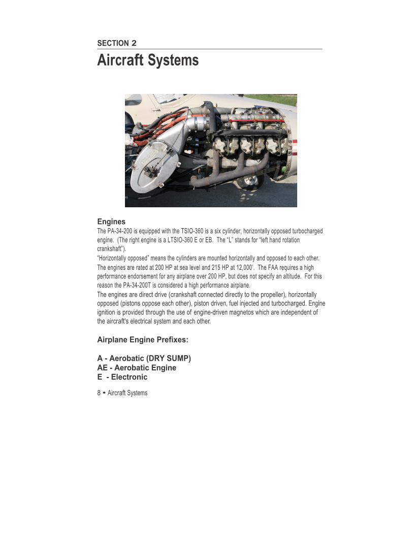
Engines The PA-34-200 is equipped with the TSIO-360 is a six cylinder, horizontally opposed turbocharged engine. (The right engine is a LTSIO-360 E or EB. The “L” stands for “left hand rotation crankshaft”). “Horizontally opposed” means the cylinders are mounted horizontally and opposed to each other. The engines are rated at 200 HP at sea level and 215 HP at 12,000’. The FAA requires a high performance endorsement for any airplane over 200 HP, but does not specify an altitude. For this reason the PA-34-200T is considered a high performance airplane. The engines are direct drive (crankshaft connected directly to the propeller), horizontally opposed (pistons oppose each other), piston driven, fuel injected and turbocharged. Engine ignition is provided through the use of engine-driven magnetos which are independent of the aircraft's electrical system and each other. Airplane Engine Prefixes: A - Aerobatic (DRY SUMP) AE - Aerobatic Engine E - Electronic
Aircraft Systems • 9
Rochester Air Center
G - Geared H - Horizontal Helicopter I - Fuel Injected L - Left Hand Rotation Crankshaft M - Drone O - Opposed Cylinders S - Supercharged T - Turbocharged V - Vertical Helicopter Oil System
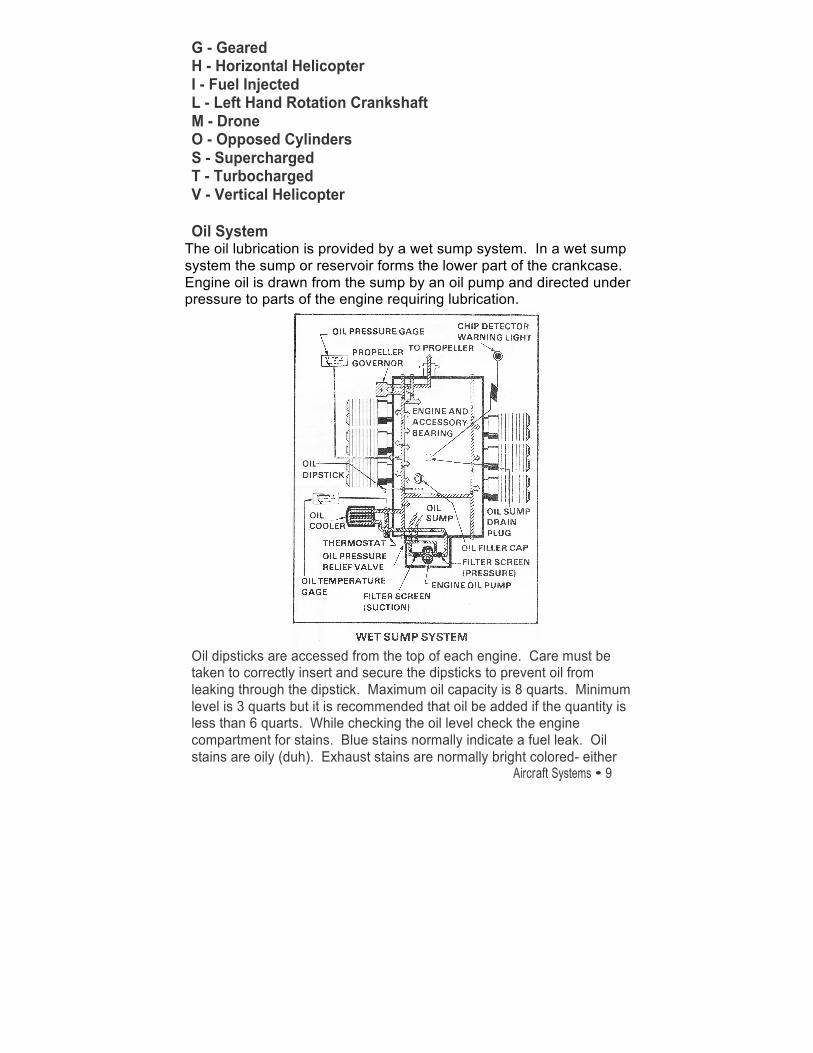
The oil lubrication is provided by a wet sump system. In a wet sump system the sump or reservoir forms the lower part of the crankcase. Engine oil is drawn from the sump by an oil pump and directed under pressure to parts of the engine requiring lubrication.
Oil dipsticks are accessed from the top of each engine. Care must be taken to correctly insert and secure the dipsticks to prevent oil from leaking through the dipstick. Maximum oil capacity is 8 quarts. Minimum level is 3 quarts but it is recommended that oil be added if the quantity is less than 6 quarts. While checking the oil level check the engine compartment for stains. Blue stains normally indicate a fuel leak. Oil stains are oily (duh). Exhaust stains are normally bright colored- either
10 • Aircraft Systems
Rochester Air Center
yellow, orange or red. If stains are detected have them checked.
Turbo Charger The TSIO-‐360 is equipped with a fixed waste gate Ray-‐Jay turbocharger on each engine that is operated by exhaust gases (contrasted with superchargers which are not powered by exhaust gases but are directly driven by the engine). Turbochargers are designed to deliver compressed air to the inlet of the fuel/air control unit and are composed of three main parts:
1. The compressor 2. The exhaust gas turbine assembly 3. The pump and bearing casing
The amount of horsepower generated by an engine largely depends on the amount of fuel and air it burns. This is why engines with a larger displacement (540 cubic inches verses 360 cubic inches), generally generate more horsepower-‐ the cylinders can inhale a greater volume of air. If we assume the fuel/air ratio is fixed (usually in piston airplane engines this is about 1:15 or 1 part fuel to 15 parts of oxygen), and the mixture is fixed, we can say that power depends on the amount of air the engine sucks in. By “amount of air” we don’t mean volume, we mean the mass of air or its weight. Take our 360 cubic inch engine. At sea level it is sucking in about 360 cubic inches of ambient air at full throttle, at sea level on a standard day. Take this engine to a high altitude airport on a hot day-‐ say El Paso, Texas (4,000’), at 2 PM in July. The engine will still draw in 360 cubic inches of air at full throttle… but the air is less dense, there are fewer molecules to pair with fuel molecules in the support of combustion. That is, there is less power from the same volume of air ; there is no point in giving the engine the same amount of fuel as you would at sea level as the engine could not burn off that excess fuel. Thus, we lean normally aspirated engines prior to take off from high elevation airports. The purpose of a turbocharger is to cram more molecules of air into the cylinder. More air in the cylinder means more fuel can be burned. More fuel burning means more horsepower. Say you want to design an airplane that will have 250 horsepower at 18,000’. You have a couple of choices-‐ you can put heavy engines rated for 500 HP at sea level on the airplane that will produce 250 HP at 18,000’, or you can put turbochargers on a 250 HP engine and get that 250 HP at
Aircraft Systems • 11
Rochester Air Center
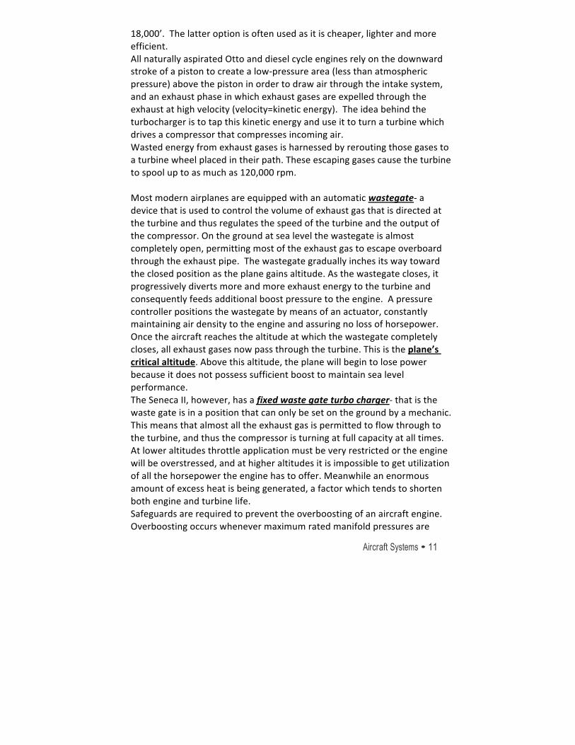
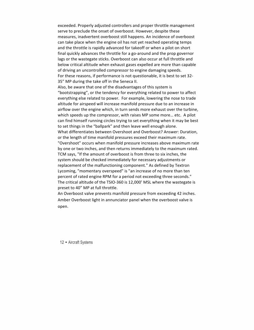
18,000’. The latter option is often used as it is cheaper, lighter and more efficient. All naturally aspirated Otto and diesel cycle engines rely on the downward stroke of a piston to create a low-‐pressure area (less than atmospheric pressure) above the piston in order to draw air through the intake system, and an exhaust phase in which exhaust gases are expelled through the exhaust at high velocity (velocity=kinetic energy). The idea behind the turbocharger is to tap this kinetic energy and use it to turn a turbine which drives a compressor that compresses incoming air. Wasted energy from exhaust gases is harnessed by rerouting those gases to a turbine wheel placed in their path. These escaping gases cause the turbine to spool up to as much as 120,000 rpm. Most modern airplanes are equipped with an automatic wastegate-‐ a device that is used to control the volume of exhaust gas that is directed at the turbine and thus regulates the speed of the turbine and the output of the compressor. On the ground at sea level the wastegate is almost completely open, permitting most of the exhaust gas to escape overboard through the exhaust pipe. The wastegate gradually inches its way toward the closed position as the plane gains altitude. As the wastegate closes, it progressively diverts more and more exhaust energy to the turbine and consequently feeds additional boost pressure to the engine. A pressure controller positions the wastegate by means of an actuator, constantly maintaining air density to the engine and assuring no loss of horsepower. Once the aircraft reaches the altitude at which the wastegate completely closes, all exhaust gases now pass through the turbine. This is the plane’s critical altitude. Above this altitude, the plane will begin to lose power because it does not possess sufficient boost to maintain sea level performance. The Seneca II, however, has a fixed waste gate turbo charger-‐ that is the waste gate is in a position that can only be set on the ground by a mechanic. This means that almost all the exhaust gas is permitted to flow through to the turbine, and thus the compressor is turning at full capacity at all times. At lower altitudes throttle application must be very restricted or the engine will be overstressed, and at higher altitudes it is impossible to get utilization of all the horsepower the engine has to offer. Meanwhile an enormous amount of excess heat is being generated, a factor which tends to shorten both engine and turbine life. Safeguards are required to prevent the overboosting of an aircraft engine. Overboosting occurs whenever maximum rated manifold pressures are
12 • Aircraft Systems
Rochester Air Center
exceeded. Properly adjusted controllers and proper throttle management serve to preclude the onset of overboost. However, despite these measures, inadvertent overboost still happens. An incidence of overboost can take place when the engine oil has not yet reached operating temps and the throttle is rapidly advanced for takeoff or when a pilot on short final quickly advances the throttle for a go-‐around and the prop governor lags or the wastegate sticks. Overboost can also occur at full throttle and below critical altitude when exhaust gases expelled are more than capable of driving an uncontrolled compressor to engine damaging speeds. For these reasons, if performance is not questionable, it is best to set 32-‐35” MP during the take off in the Seneca II. Also, be aware that one of the disadvantages of this system is “bootstrapping”, or the tendency for everything related to power to affect everything else related to power. For example, lowering the nose to trade altitude for airspeed will increase manifold pressure due to an increase in airflow over the engine which, in turn sends more exhaust over the turbine, which speeds up the compressor, with raises MP some more… etc. A pilot can find himself running circles trying to set everything when it may be best to set things in the “ballpark” and then leave well enough alone. What differentiates between Overshoot and Overboost? Answer: Duration, or the length of time manifold pressures exceed their maximum rate. "Overshoot" occurs when manifold pressure increases above maximum rate by one or two inches, and then returns immediately to the maximum rated. TCM says, "If the amount of overboost is from three to six inches, the system should be checked immediately for necessary adjustments or replacement of the malfunctioning component." As defined by Textron Lycoming, "momentary overspeed" is "an increase of no more than ten percent of rated engine RPM for a period not exceeding three seconds." The critical altitude of the TSIO-‐360 is 12,000’ MSL where the wastegate is preset to 40” MP at full throttle. An Overboost valve prevents manifold pressure from exceeding 42 inches. Amber Overboost light in annunciator panel when the overboost valve is
open.
Aircraft Systems • 13
Rochester Air Center
Warning Because of the high temperatures and pressures produced in the turbine exhaust systems, any malfunction of the turbocharger must be treated with extreme caution. Low manifold pressure may indicate an exhaust gas leak which is extremely hazardous. If this occurs shut the engine down unless a greater emergency exists that warrants keeping the engine operating. If continuing to operate the engine, use the lowest power setting demanded by the situation and land as soon as practicable. Do not fly the airplane until maintenance has been performed. Fuel Injection
14 • Aircraft Systems
Rochester Air Center
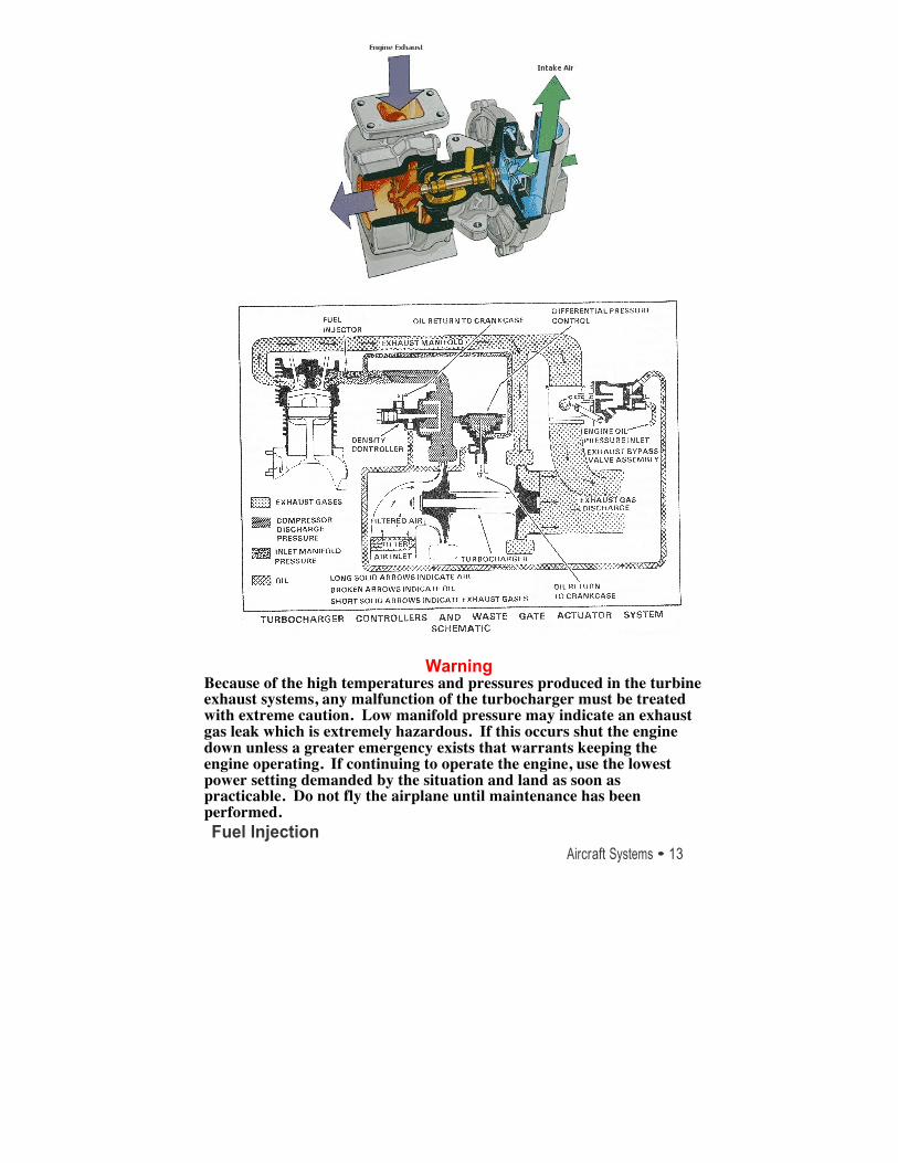
The Continental 360 engine drives a positive-displacement, vane-type fuel pump, which has the ability to supply over twice the fuel needed for proper engine operation at any power setting. Driven from a pad on the right-front side of the crankcase, the fuel pump takes gravity-fed fuel and boosts the pressure to over 46 psi at takeoff power on some models of the TSIO-360 series engine. In order to get this pressure, the fuel must flow through a series of check valves and adjustable orifices, which adjust flow and pressure for a given engine rpm.
In a fuel injection system, the fuel is injected either directly into the cylinders, or just ahead of the intake valve. A fuel injection system is considered to be less susceptible to icing than the carburetor system. Impact icing on the air intake, however, is a possibility in either system. Impact icing occurs when ice forms on the exterior of the airplane, and blocks openings such as the air intake for the injection system.
The air intake for the fuel injection system is similar to that used in the carburetor system, with an alternate air source located within the engine cowling. This source is used if the external air source is obstructed. The alternate air source is usually operated automatically, with a backup manual system that can be used if the automatic feature malfunctions.
A fuel injection system usually incorporates these basic components—an engine-driven fuel pump, a fuel/air control unit,
Aircraft Systems • 15
Rochester Air Center
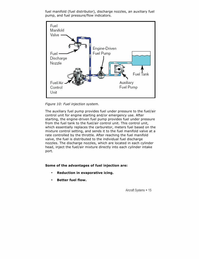
fuel manifold (fuel distributor), discharge nozzles, an auxiliary fuel pump, and fuel pressure/flow indicators.
Figure 10: Fuel injection system.
The auxiliary fuel pump provides fuel under pressure to the fuel/air control unit for engine starting and/or emergency use. After starting, the engine-driven fuel pump provides fuel under pressure from the fuel tank to the fuel/air control unit. This control unit, which essentially replaces the carburetor, meters fuel based on the mixture control setting, and sends it to the fuel manifold valve at a rate controlled by the throttle. After reaching the fuel manifold valve, the fuel is distributed to the individual fuel discharge nozzles. The discharge nozzles, which are located in each cylinder head, inject the fuel/air mixture directly into each cylinder intake port.
Some of the advantages of fuel injection are:
• Reduction in evaporative icing.
• Better fuel flow.
16 • Aircraft Systems
Rochester Air Center
• Faster throttle response.
• Precise control of mixture.
• Better fuel distribution.
• Easier cold weather starts.
Disadvantages usually include:
• Difficulty in starting a hot engine.
• Vapor locks during ground operations on hot days.
• Problems associated with restarting an engine that quits because of fuel starvation.
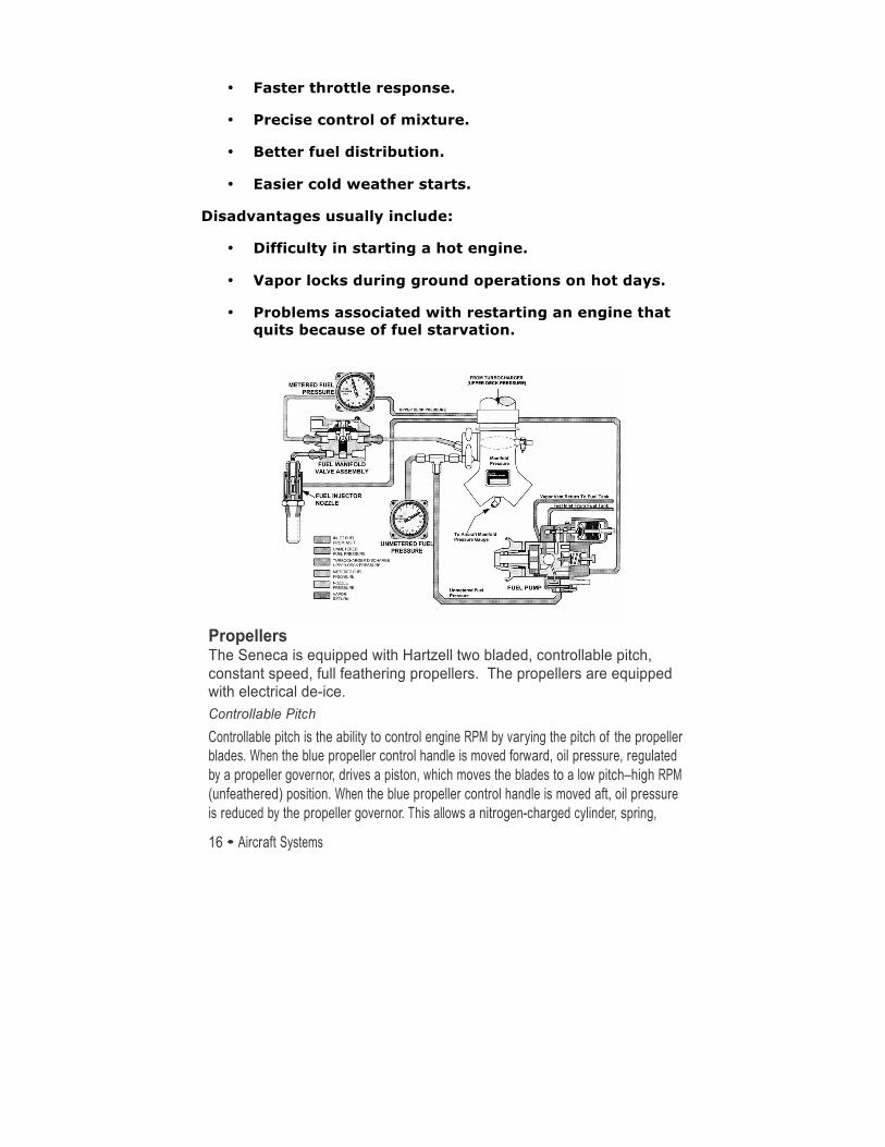
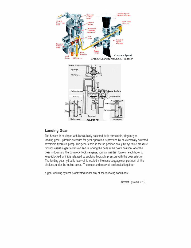
Propellers The Seneca is equipped with Hartzell two bladed, controllable pitch, constant speed, full feathering propellers. The propellers are equipped with electrical de-ice. Controllable Pitch Controllable pitch is the ability to control engine RPM by varying the pitch of the propeller blades. When the blue propeller control handle is moved forward, oil pressure, regulated by a propeller governor, drives a piston, which moves the blades to a low pitch–high RPM (unfeathered) position. When the blue propeller control handle is moved aft, oil pressure is reduced by the propeller governor. This allows a nitrogen-charged cylinder, spring,
Aircraft Systems • 17
Rochester Air Center
and centrifugal counterweights to drive the blades to a high pitch–low RPM (feathered) position.
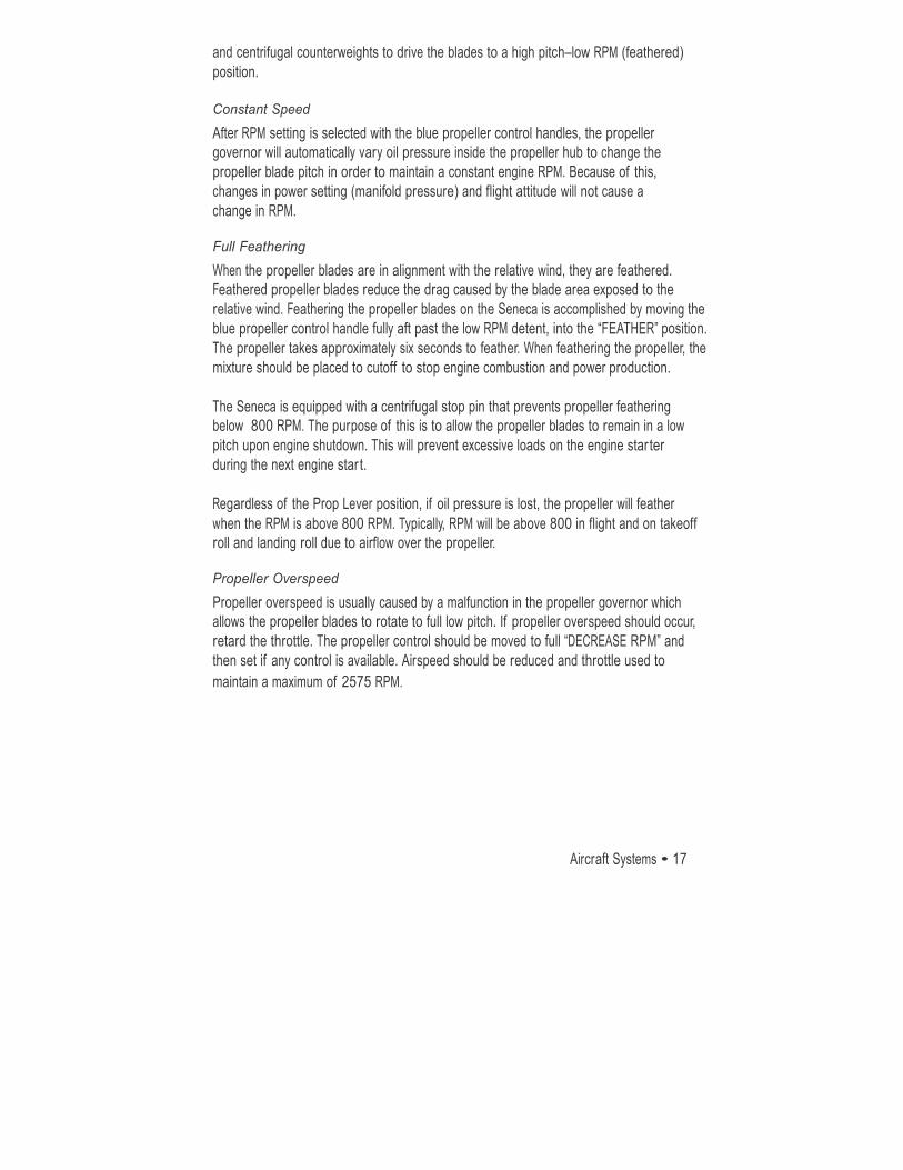
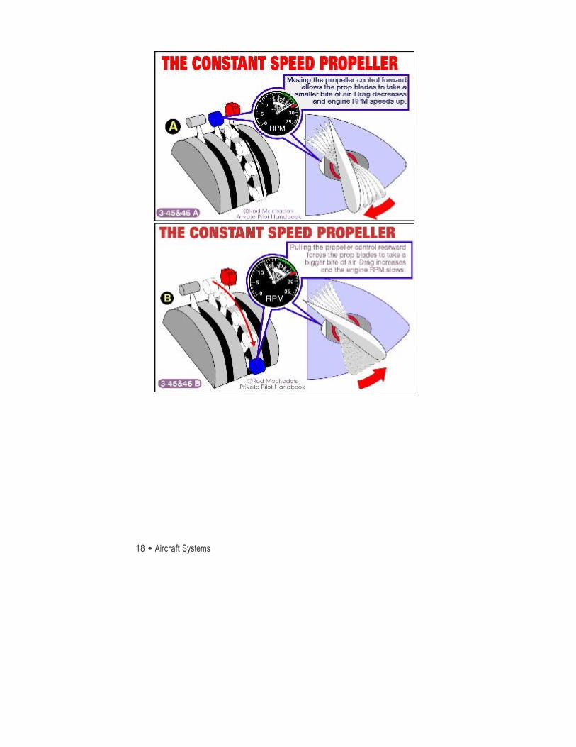
Constant Speed After RPM setting is selected with the blue propeller control handles, the propeller governor will automatically vary oil pressure inside the propeller hub to change the propeller blade pitch in order to maintain a constant engine RPM. Because of this, changes in power setting (manifold pressure) and flight attitude will not cause a change in RPM.
Full Feathering When the propeller blades are in alignment with the relative wind, they are feathered. Feathered propeller blades reduce the drag caused by the blade area exposed to the relative wind. Feathering the propeller blades on the Seneca is accomplished by moving the blue propeller control handle fully aft past the low RPM detent, into the “FEATHER” position. The propeller takes approximately six seconds to feather. When feathering the propeller, the mixture should be placed to cutoff to stop engine combustion and power production.
The Seneca is equipped with a centrifugal stop pin that prevents propeller feathering below 800 RPM. The purpose of this is to allow the propeller blades to remain in a low pitch upon engine shutdown. This will prevent excessive loads on the engine star ter during the next engine star t.
Regardless of the Prop Lever position, if oil pressure is lost, the propeller will feather when the RPM is above 800 RPM. Typically, RPM will be above 800 in flight and on takeoff roll and landing roll due to airflow over the propeller.
Propeller Overspeed Propeller overspeed is usually caused by a malfunction in the propeller governor which allows the propeller blades to rotate to full low pitch. If propeller overspeed should occur, retard the throttle. The propeller control should be moved to full “DECREASE RPM” and then set if any control is available. Airspeed should be reduced and throttle used to maintain a maximum of 2575 RPM.
18 • Aircraft Systems
Rochester Air Center
Aircraft Systems • 19
Rochester Air Center
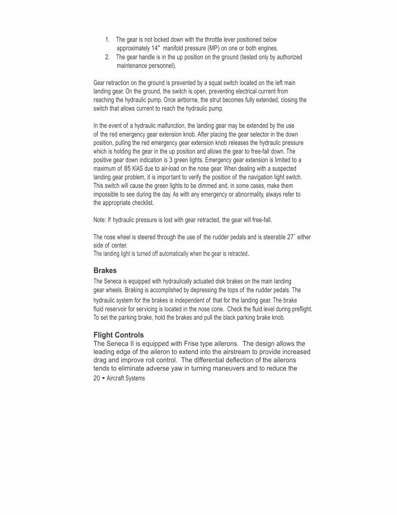
Landing Gear The Seneca is equipped with hydraulically actuated, fully retractable, tricycle-type landing gear. Hydraulic pressure for gear operation is provided by an electrically powered, reversible hydraulic pump. The gear is held in the up position solely by hydraulic pressure. Springs assist in gear extension and in locking the gear in the down position. After the gear is down and the downlock hooks engage, springs maintain force on each hook to keep it locked until it is released by applying hydraulic pressure with the gear selector. The landing gear hydraulic reservoir is located in the nose baggage compartment of the airplane, under the locked cover. The motor and reservoir are located together.
A gear warning system is activated under any of the following conditions:
20 • Aircraft Systems
Rochester Air Center
1. The gear is not locked down with the throttle lever positioned below approximately 14" manifold pressure (MP) on one or both engines.
2. The gear handle is in the up position on the ground (tested only by authorized maintenance personnel).
Gear retraction on the ground is prevented by a squat switch located on the left main landing gear. On the ground, the switch is open, preventing electrical current from reaching the hydraulic pump. Once airborne, the strut becomes fully extended, closing the switch that allows current to reach the hydraulic pump.
In the event of a hydraulic malfunction, the landing gear may be extended by the use of the red emergency gear extension knob. After placing the gear selector in the down position, pulling the red emergency gear extension knob releases the hydraulic pressure which is holding the gear in the up position and allows the gear to free-fall down. The positive gear down indication is 3 green lights. Emergency gear extension is limited to a maximum of 85 KIAS due to air-load on the nose gear. When dealing with a suspected landing gear problem, it is impor tant to verify the position of the navigation light switch. This switch will cause the green lights to be dimmed and, in some cases, make them impossible to see during the day. As with any emergency or abnormality, always refer to the appropriate checklist.
Note: If hydraulic pressure is lost with gear retracted, the gear will free-fall.
The nose wheel is steered through the use of the rudder pedals and is steerable 27˚ either side of center. The landing light is turned off automatically when the gear is retracted.
Brakes The Seneca is equipped with hydraulically actuated disk brakes on the main landing gear wheels. Braking is accomplished by depressing the tops of the rudder pedals. The hydraulic system for the brakes is independent of that for the landing gear. The brake fluid reservoir for servicing is located in the nose cone. Check the fluid level during preflight. To set the parking brake, hold the brakes and pull the black parking brake knob.
Flight Controls The Seneca II is equipped with Frise type ailerons. The design allows the leading edge of the aileron to extend into the airstream to provide increased drag and improve roll control. The differential deflection of the ailerons tends to eliminate adverse yaw in turning maneuvers and to reduce the
Aircraft Systems • 21
Rochester Air Center
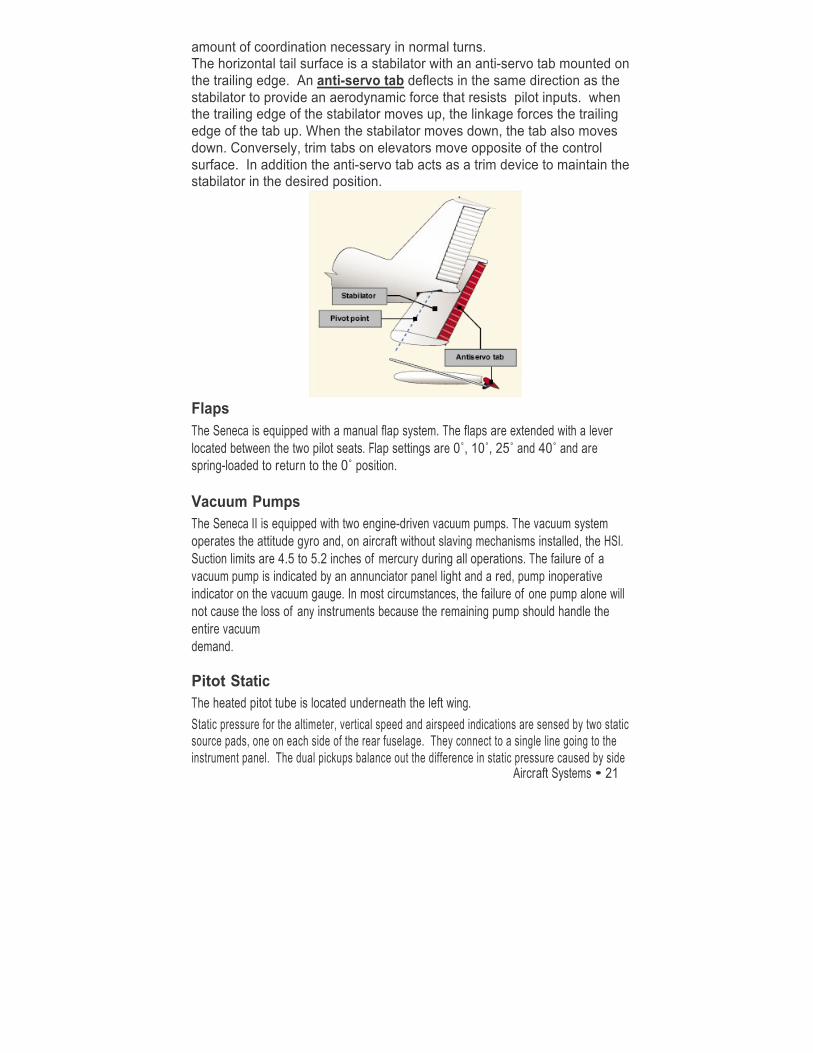
amount of coordination necessary in normal turns. The horizontal tail surface is a stabilator with an anti-servo tab mounted on the trailing edge. An anti-servo tab deflects in the same direction as the stabilator to provide an aerodynamic force that resists pilot inputs. when the trailing edge of the stabilator moves up, the linkage forces the trailing edge of the tab up. When the stabilator moves down, the tab also moves down. Conversely, trim tabs on elevators move opposite of the control surface. In addition the anti-servo tab acts as a trim device to maintain the stabilator in the desired position.
Flaps The Seneca is equipped with a manual flap system. The flaps are extended with a lever located between the two pilot seats. Flap settings are 0˚, 10˚, 25˚ and 40˚ and are spring-loaded to return to the 0˚ position.
Vacuum Pumps The Seneca II is equipped with two engine-driven vacuum pumps. The vacuum system operates the attitude gyro and, on aircraft without slaving mechanisms installed, the HSI. Suction limits are 4.5 to 5.2 inches of mercury during all operations. The failure of a vacuum pump is indicated by an annunciator panel light and a red, pump inoperative indicator on the vacuum gauge. In most circumstances, the failure of one pump alone will not cause the loss of any instruments because the remaining pump should handle the entire vacuum demand.
Pitot Static The heated pitot tube is located underneath the left wing. Static pressure for the altimeter, vertical speed and airspeed indications are sensed by two static source pads, one on each side of the rear fuselage. They connect to a single line going to the instrument panel. The dual pickups balance out the difference in static pressure caused by side

22 • Aircraft Systems
Rochester Air Center
slips or skids. An alternate static source is located inside the cabin under the instrument panel to the right of the throttle quadrant for use in the event of static por t blockage. When using the alternate static source, the storm window and cabin vents must be closed, and the heater and defroster must be turned on. This will reduce the pressure differential between the cockpit and the atmosphere, reducing pitot static error. The pitot static instruments are the airspeed indicator, altimeter, and VSI. Fuel System The Seneca II, which uses 100 low lead avgas (blue), is equipped with two standard (three optional), interconnected fuel tanks in each wing that function as a single tank. With the standard tanks there is 93 usable gallons; with the auxiliary tanks installed (RAC version), there is 123 usable gallons installed.
There are two engine-driven and two electrically driven fuel pumps. The electric fuel pumps are used for providing the engine with fuel in the case of an engine driven fuel pump shaft failure or malfunction.The two auxiliary pumps are located on the electrical side panel and are three position rocker switchs; LO, HI and OFF. The HI pressure is selected by pushing the bottom of the switch but can only be done after unlatching a guard switch. When the HI auxiliary pump is activated an amber light near the annunciation panel is illuminated. This light dims when the pump pressure reduces automatically and manifold pressure is below approximately 21”. Separate spring loaded OFF primer buttons are located adjacent to the starter switches and are used for priming.
The aircraft is equipped with a three-position fuel selector for each engine. The positions are “ON”, “OFF”, and “X-FEED” (cross feed). The fuel selectors remain in the “ON” position during normal operations, and each engine draws fuel from the tank on the same side as the engine. When “X-FEED” is selected, the engine draws fuel from the tank on the opposite side. Fuel cannot be transferred from tank to tank. Crossfeed operation is limited to straight and level flight only.
. Electrical System The Seneca is equipped with a 14-volt electrical system which utilizes push-pull type circuit breakers; a 12-volt, 35 amp hour battery; and two 65-amp, engine-driven alternators. Voltage regulators maintain constant 14-volt output from each alternator at varying engine RPMs, effectively sharing the electrical load. Loss of one alternator is indicated by an annunciator light and a zero indication on the loadmeter. The remaining
Aircraft Systems • 23
Rochester Air Center
alternator will normally provide adequate electrical power.
Over-voltage protection is provided if system voltage exceeds 17 volts. If an over-voltage occurs the battery is then the sole source of electrical power. The battery is used as a source of emergency electrical power and for engine star ts. High drain items include the lights, vent fan, heater, gear hydraulic pump, and radios. If an electrical problem arises, always check circuit breakers. If a circuit breaker is popped, reset only one time. Heater Heat to the cabin is supplied by a Janitrol gas combustion heater located in the aft fuselage behind the cabin baggage compartment close off. Air from the heater is ducted forward by a manifold to the ducts along the cabin floor to outlets at each seat and to the defroster outlet. Operation of the heater is controlled by a three-position switch located on the instrument panel labeled “HEATER”, “OFF”, and “FAN.” Airflow and temperature are regulated by the two levers on the consul: the left hand lever regulates air intake and the left-handed lever regulates cabin temperature.
For cabin heat, the “AIR INTAKE” lever must be partially or fully open and the “CABIN HEAT” switch to the “HEATER” position. This simultaneously star ts fuel flow and ignites the heater. During ground operation, it also activates the ventilation blower. When cabin air reaches the temperature selected on the “TEMP” lever, ignition of the heater cycles automatically to maintain the selected temperature.
An overheat switch in the heater acts as a safety device to render the heater inoperative if a malfunction should occur. Should the switch deactivate the heater, the red “OVERHEAT” light on the consul will illuminate. The overheat switch is located on the forward outboard end of the heater vent jacket. A red reset button is located on the heater shroud can be reached through the bulkhead access panel in the aft cabin close-out panel.
To prevent activation of the overheat switch upon normal heater shutdown during ground operation, turn the three-position switch to “FAN” for two minutes with the air intake lever in the open position before turning the switch off. During flight, leave the air intake open for a minimum of 15 seconds after turning the switch to off.
Fuel is supplied to the heater at a rate of ½ gallon per hour from downstream of the left fuel selector and filter.
24 • Aircraft Systems
Rochester Air Center
Stall Warning Horn The Seneca II is equipped with two heated electric stall detectors located on the left wing. The inboard detector provides stall warning at flaps 25˚ or 40˚ and the outboard at flaps 0˚or 10˚. The purpose of the two tabs is to provide adequate stall warning at varied angles of attack. The electric stall tabs are deactivated on the ground through the use of the squat switch on the left main landing gear.
Ice Protection System RAC’s Seneca II is equipped with the optional ice protection system. The system consists of the of the following equipment: 1. Pneumatic wing and empennage boots 2. Wing ice detection light (left wing) 3. Electrothermal propeller deice pads 4. Electric windshield panel 5. Heated lift detectors, and heated pitot head.
All these systems must be operational for flight into known icing conditions.
The pneumatic wing and empennage boots are installed on the leading edge of the wings, the vertical stabilizer and the horizontal stabiliator. During normal operation with the surface deicer turned off, the engine-driven pressure pumps apply a constant suction to the deicer boots to provide a smooth, streamlined leading edge. Activation of the surface deice switch (mounted above the engine quadrant), actives the pneumatic system control valves for six seconds and closes the circuit for the blue light on the deice control panel. The blue light indicates the boot inflation cycle has been activated. When the boots have been inflated to their normal valves and turns the inflation indicator light off. The boots then deflate and the system returns to the vacuum hold-down mode. Note- If the blue indicator light remains illuminated for more than 20 seconds there is a problem with the system. Electrothermal deice pads are bonded to the leading edge of the propeller blades. The system is controlled by an “On-Off” type switch on the deice panel. When the prop deice is activated, power is monitored by the “Prop De-icer” ammeter which monitors the current through the propeller deicing system. With the propeller deice system on, the prop deicer ammeter needle should indicate within the shaded
Aircraft Systems • 25
Rochester Air Center
portion of the ammeter for a normal reading. The propellers are heated in a timed sequence Preflight of the deicers can be performed by turning on the prop deice switch and feeling the propeller deice pads for proper heating sequence. The heated glass panel is installed on the exterior of the pilot’s windshield to provide visibility in icing conditions. The panel is heated by current from the airplane’s electrical system. On operational check may be performed by turning the heated windshield to the on position for a period not exceeding 30 seconds.
Pressurization (Commercial and ATP Only)
When an airplane is flown at a high altitude, it consumes less fuel for a given airspeed than it does for the same speed at a lower altitude. In other words, the airplane is more efficient at a high altitude. In addition, bad weather and turbulence may be avoided by flying in the relatively smooth air above the storms. Because of the advantages of flying at high altitudes, many modern general aviation-type airplanes are being designed to operate in that environment. It is important that pilots transitioning to such sophisticated equipment be familiar with at least the basic operating principles.
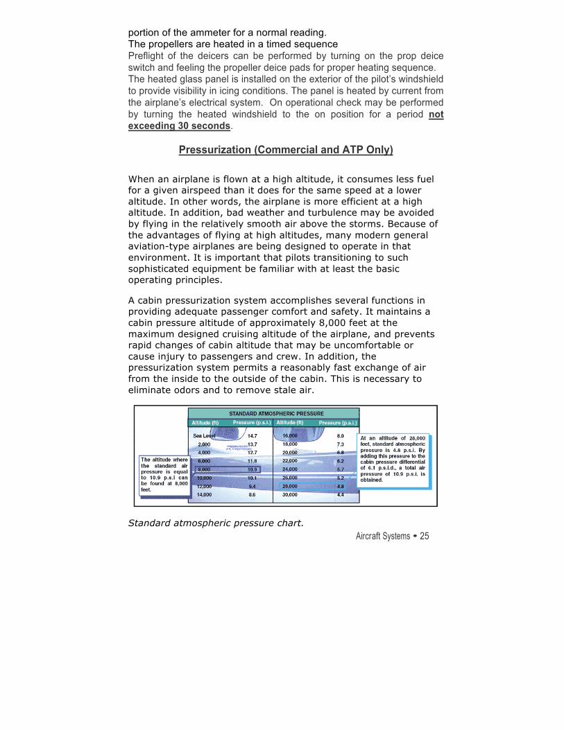
A cabin pressurization system accomplishes several functions in providing adequate passenger comfort and safety. It maintains a cabin pressure altitude of approximately 8,000 feet at the maximum designed cruising altitude of the airplane, and prevents rapid changes of cabin altitude that may be uncomfortable or cause injury to passengers and crew. In addition, the pressurization system permits a reasonably fast exchange of air from the inside to the outside of the cabin. This is necessary to eliminate odors and to remove stale air.
Standard atmospheric pressure chart.
26 • Aircraft Systems
Rochester Air Center
Pressurization of the airplane cabin is an accepted method of protecting occupants against the effects of hypoxia. Within a pressurized cabin, occupants can be transported comfortably and safely for long periods of time, particularly if the cabin altitude is maintained at 8,000 feet or below, where the use of oxygen equipment is not required. The flight crew in this type of airplane must be aware of the danger of accidental loss of cabin pressure and must be prepared to deal with such an emergency whenever it occurs.
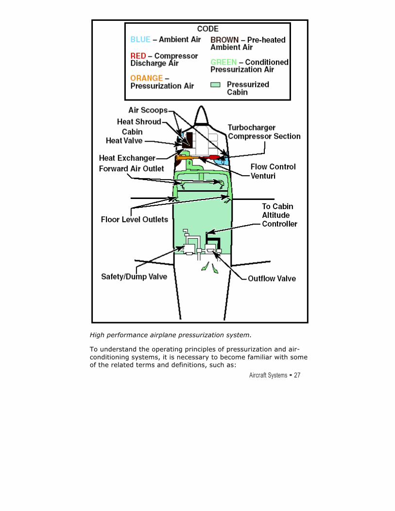
In the typical pressurization system, the cabin, flight compartment, and baggage compartments are incorporated into a sealed unit that is capable of containing air under a pressure higher than outside atmospheric pressure. On aircraft powered by turbine engines, bleed air from the engine compressor section is used to pressurize the cabin. Superchargers may be used on older model turbine powered airplanes to pump air into the sealed fuselage. Piston-powered airplanes may use air supplied from each engine turbocharger through a sonic venturi (flow limiter). Air is released from the fuselage by a device called an outflow valve. The outflow valve, by regulating the air exit, provides a constant inflow of air to the pressurized area.
Aircraft Systems • 27
Rochester Air Center
High performance airplane pressurization system.
To understand the operating principles of pressurization and air-conditioning systems, it is necessary to become familiar with some of the related terms and definitions, such as:
28 • Aircraft Systems
Rochester Air Center
• Aircraft altitude—the actual height above sea level at which the airplane is flying.
• Ambient temperature—the temperature in the area immediately surrounding the airplane.
• Ambient pressure—the pressure in the area immediately surrounding the airplane.
• Cabin altitude—used to express cabin pressure in terms of equivalent altitude above sea level.
• Differential pressure—the difference in pressure between the pressure acting on one side of a wall and the pressure acting on the other side of the wall. In aircraft air-conditioning and pressurizing systems, it is the difference between cabin pressure and atmospheric pressure.
The cabin pressure control system provides cabin pressure regulation, pressure relief, vacuum relief, and the means for selecting the desired cabin altitude in the isobaric and differential range. In addition, dumping of the cabin pressure is a function of the pressure control system. A cabin pressure regulator, an outflow valve, and a safety valve are used to accomplish these functions.
The cabin pressure regulator controls cabin pressure to a selected value in the isobaric range and limits cabin pressure to a preset differential value in the differential range. When the airplane reaches the altitude at which the difference between the pressure inside and outside the cabin is equal to the highest differential pressure for which the fuselage structure is designed, a further increase in airplane altitude will result in a corresponding increase in cabin altitude. Differential control is used to prevent the maximum differential pressure, for which the fuselage was designed, from being exceeded. This differential pressure is determined by the structural strength of the cabin and often by the relationship of the cabin size to the probable areas of rupture, such as window areas and doors.
The cabin air pressure safety valve is a combination pressure relief, vacuum relief, and dump valve. The pressure relief valve prevents cabin pressure from exceeding a predetermined differential pressure above ambient pressure. The vacuum relief prevents ambient pressure from exceeding cabin pressure by
Aircraft Systems • 29
Rochester Air Center
allowing external air to enter the cabin when ambient pressure exceeds cabin pressure. The cockpit control switch actuates the dump valve. When this switch is positioned to ram, a solenoid valve opens, causing the valve to dump cabin air to atmosphere.
The degree of pressurization and the operating altitude of the aircraft are limited by several critical design factors. Primarily the fuselage is designed to withstand a particular maximum cabin differential pressure.
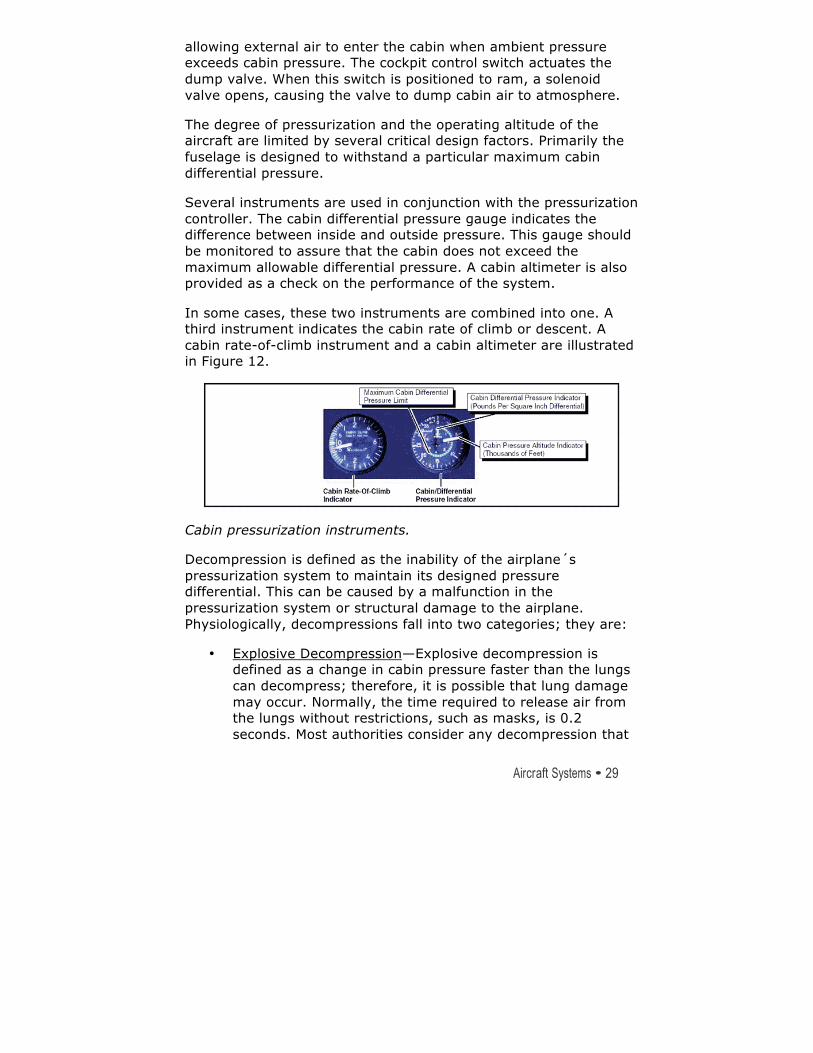
Several instruments are used in conjunction with the pressurization controller. The cabin differential pressure gauge indicates the difference between inside and outside pressure. This gauge should be monitored to assure that the cabin does not exceed the maximum allowable differential pressure. A cabin altimeter is also provided as a check on the performance of the system.
In some cases, these two instruments are combined into one. A third instrument indicates the cabin rate of climb or descent. A cabin rate-of-climb instrument and a cabin altimeter are illustrated in Figure 12.
Cabin pressurization instruments.
Decompression is defined as the inability of the airplane´s pressurization system to maintain its designed pressure differential. This can be caused by a malfunction in the pressurization system or structural damage to the airplane. Physiologically, decompressions fall into two categories; they are:
• Explosive Decompression—Explosive decompression is defined as a change in cabin pressure faster than the lungs can decompress; therefore, it is possible that lung damage may occur. Normally, the time required to release air from the lungs without restrictions, such as masks, is 0.2 seconds. Most authorities consider any decompression that
30 • Aircraft Systems
Rochester Air Center
occurs in less than 0.5 seconds as explosive and potentially dangerous.
• Rapid Decompression—Rapid decompression is defined as a change in cabin pressure where the lungs can decompress faster than the cabin; therefore, there is no likelihood of lung damage.
During an explosive decompression, there may be noise, and for a split second, one may feel dazed. The cabin air will fill with fog, dust, or flying debris. Fog occurs due to the rapid drop in temperature and the change of relative humidity. Normally, the ears clear automatically. Air will rush from the mouth and nose due to the escape of air from the lungs, and may be noticed by some individuals.
The primary danger of decompression is hypoxia.
Unless proper utilization of oxygen equipment is accomplished quickly, unconsciousness may occur in a very short time. The period of useful consciousness is considerably shortened when a person is subjected to a rapid decompression. This is due to the rapid reduction of pressure on the body—oxygen in the lungs is exhaled rapidly. This in effect reduces the partial pressure of oxygen in the blood and therefore reduces the pilot´s effective performance time by one-third to one-fourth its normal time. For this reason, the oxygen mask should be worn when flying at very high altitudes (35,000 feet or higher). It is recommended that the crewmembers select the 100 percent oxygen setting on the oxygen regulator at high altitude if the airplane is equipped with a demand or pressure demand oxygen system.
Another hazard is being tossed or blown out of the airplane if near an opening. For this reason, individuals near openings should wear safety harnesses or seatbelts at all times when the airplane is pressurized and they are seated.
Another potential hazard during high altitude decompressions is the possibility of evolved gas decompression sicknesses. Exposure to wind blasts and extremely cold temperatures are other hazards one might have to face.
Aircraft Systems • 31
Rochester Air Center
Rapid descent from altitude is necessary if these problems are to be minimized. Automatic visual and aural warning systems are included in the equipment of all pressurized airplanes.
Inoperative Instruments and Equipment per FAR 91.213 RAC’s aircraft do not operate under the guidance of a minimum equipment list (MEL). RAC’s aircraft operate in accordance with the following FAR 91.213(d). 91.213(d) states that items may be inoperative as long as they are not part of: 1. Part of the VFR-day type certification instruments and equipment prescribed in the applicable airworthiness regulation. This is FAR 23. Some key items listed in FAR 23 that are installed on the PA34-200T a) stall horn b) CHT (due to cowl flaps) 2. Indicated as required on the equipment list of Kinds of Operations List (KOL). 3. Required by 91.205 (TOMATOFLAMES), or any other FAR. 4. Required to be operational by an AD. Because this is only an excerpt, the complete subpar t should be referred to if necessary:
(3) The inoperative instruments and equipment are --
(i) Removed from the aircraft, the cockpit control placarded, and the maintenance recorded in accordance with §43.9 of this chapter; or (ii) Deactivated and placarded “Inoperative.” If deactivation of the inoperative instrument or equipment involves maintenance, it must be accomplished and recorded in accordance with par t 43 of this chapter;
(4) A determination is made by a pilot, who is cer tificated and appropriately rated under par t 61 of this chapter, or by a person, who is cer tificated and appropriately rated to perform maintenance on the aircraft, that the inoperative instrument or equipment does not constitute a hazard to the aircraft.
Rochester Air Center
Performance/W&B • 32
SECTION 3
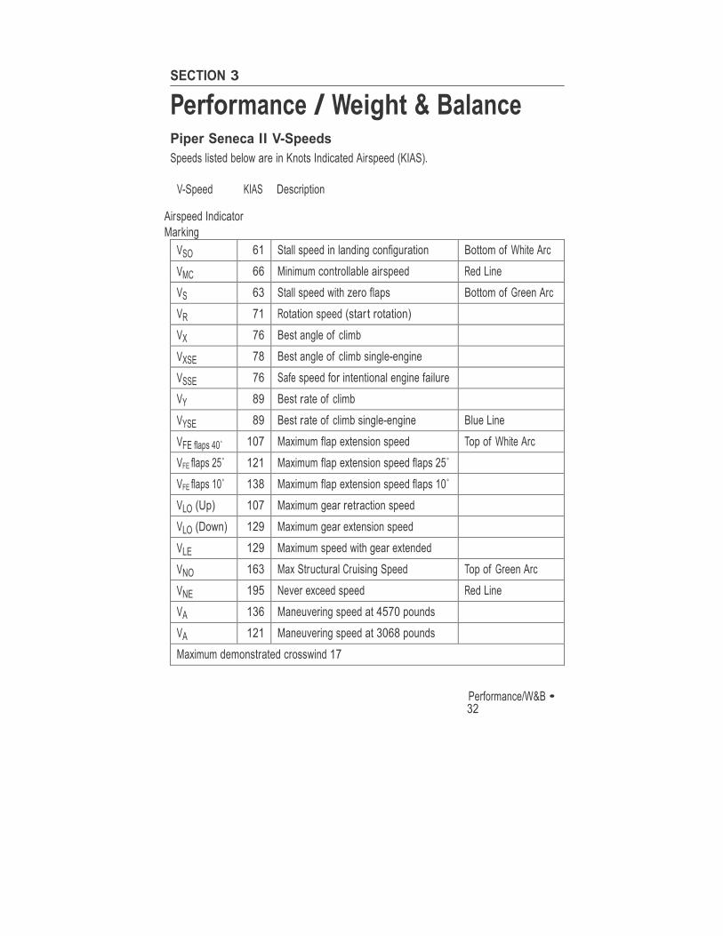
Performance / Weight & Balance Piper Seneca II V-Speeds Speeds listed below are in Knots Indicated Airspeed (KIAS).
V-Speed KIAS Description
Airspeed Indicator Marking
VSO 61 Stall speed in landing configuration Bottom of White Arc VMC 66 Minimum controllable airspeed Red Line VS 63 Stall speed with zero flaps Bottom of Green Arc VR 71 Rotation speed (star t rotation) VX 76 Best angle of climb VXSE 78 Best angle of climb single-engine VSSE 76 Safe speed for intentional engine failure VY 89 Best rate of climb VYSE 89 Best rate of climb single-engine Blue Line VFE flaps 40˚ 107 Maximum flap extension speed Top of White Arc VFE flaps 25˚ 121 Maximum flap extension speed flaps 25˚
VFE flaps 10˚ 138 Maximum flap extension speed flaps 10˚
VLO (Up) 107 Maximum gear retraction speed VLO (Down) 129 Maximum gear extension speed VLE 129 Maximum speed with gear extended VNO 163 Max Structural Cruising Speed Top of Green Arc VNE 195 Never exceed speed Red Line VA 136 Maneuvering speed at 4570 pounds VA 121 Maneuvering speed at 3068 pounds Maximum demonstrated crosswind 17
Rochester Air Center
33 • Performance/W&B
Rochester Air Center
Performance/W&B • 34
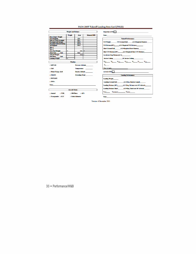
Takeoff Landing Card Information
The Preflight Data Card is to be filed out prior to every flight lesson by the student; assistance from the instructor will be provided when required. This card is designed to ensure that the student is familiar with all
necessary preflight data, and is organized in a manner that makes it a useful tool for organizing the information that you will be using for any particular flight.
The front side of the card is to be used as a preflight prep guide for the
information that you will need. Also complete the boxed items on the reverse side prior to departing.
Weight & Balance Grid
• The weight and balance grid is a setup in a logical order and can be completed by the use of either a loading chart, or the weight * arm = moment method. Once the takeoff weight and CG have been computed, the landing weight is calculated simply by subtracting the weight of the fuel burned for the flight. ( Weight of avgas is 6 lbs/gallon, average flight lesson time is 1.5 hours)
Weather Section
• Pressure altitude, temperature, and the prevailing wind can be obtained from a recent observation and are used for the performance calculations. Use the maximum pressure altitude and temperature anticipated for the time period. Density altitude is to be calculated for every flight and should be an emphasis item in the summer months.
• The remainder of the weather items are to be used as an aid in obtaining a good picture of the local weather. For the specific reports listed simply checking the report and placing a check in the required check box is sufficient. If there is anything that the student or the instructor feels is noteworthy you may use the provided space to record the pertinent information. The items
Rochester Air Center
35 • Performance/W&B
listed on the card should be printed out and available and discussed with the examiner during the checkride.
Aircraft Status Section
• The aircraft status section of the preflight data card is to be used to ensure that the required inspections are complete. These inspections can be verified with the use of the aircraft inspection status page in the aircraft book. If there are any questions or discrepancies they can be verified by the use of the aircraft logbooks. Once verified place a check in the checkbox provided.
The second page of the card is to be used as an in-‐flight guide for the
information that you will need.
• The top row serves as a place to record the departure ATIS. (The box is for the identifier)
• The blank area is for the clearance and any applicable notes.
Takeoff Performance Box
• The takeoff performance section of this card contains all takeoff performance parameters that the pilot must be familiar with prior to departing. Make sure when using the charts that the optional landing gear charts are NOT used.
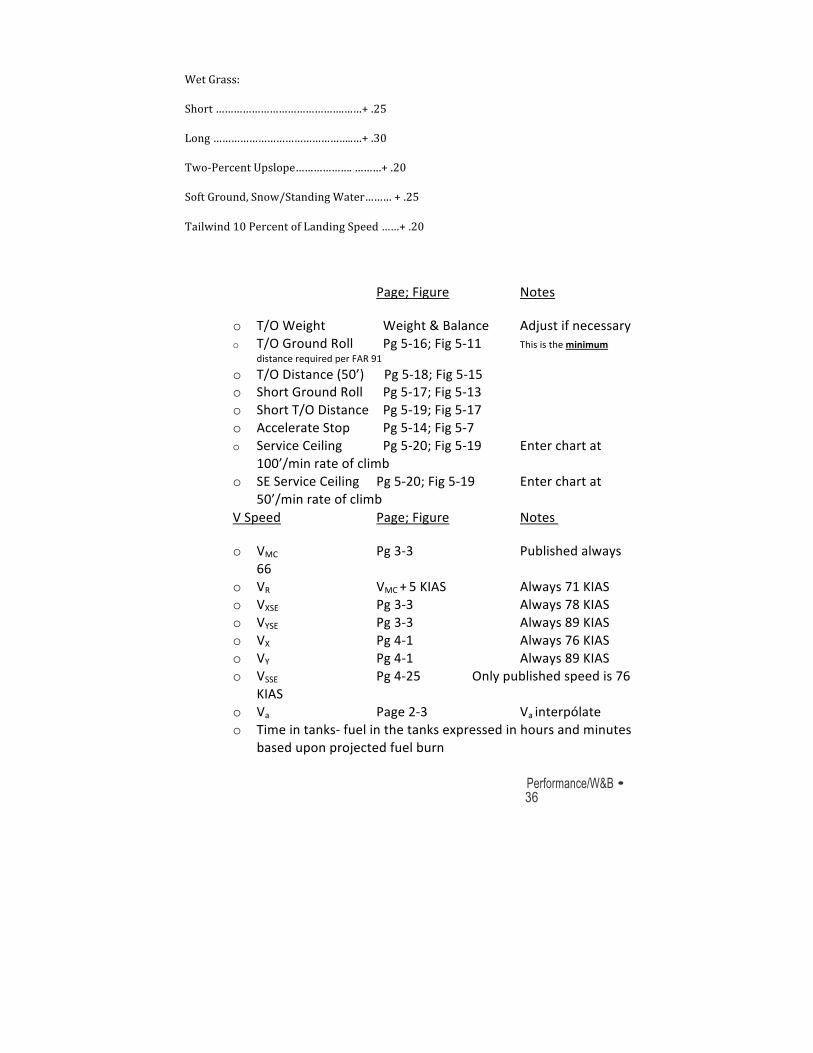
• After computing the book number, multiply performance numbers by 1.5 in ideal conditions to give a safety buffer. If conditions are not ideal, use the following table as a rule of thumb. Note that these penalties are cumulative.
Condition Fudge Factor
Dry Grass:
Short (< 5 inches)……………………………+ .20
High (5-‐10 inches) ……………………….….+ .25
Rochester Air Center
Performance/W&B • 36
Wet Grass:
Short …………………………………….……+ .25
Long ………………………………………..…+ .30
Two-‐Percent Upslope………………. ………+ .20
Soft Ground, Snow/Standing Water……… + .25
Tailwind 10 Percent of Landing Speed ……+ .20
Page; Figure Notes
o T/O Weight Weight & Balance Adjust if necessary o T/O Ground Roll Pg 5-‐16; Fig 5-‐11 This is the minimum
distance required per FAR 91
o T/O Distance (50’) Pg 5-‐18; Fig 5-‐15 o Short Ground Roll Pg 5-‐17; Fig 5-‐13 o Short T/O Distance Pg 5-‐19; Fig 5-‐17 o Accelerate Stop Pg 5-‐14; Fig 5-‐7 o Service Ceiling Pg 5-‐20; Fig 5-‐19 Enter chart at
100’/min rate of climb
o SE Service Ceiling Pg 5-‐20; Fig 5-‐19 Enter chart at 50’/min rate of climb
V Speed Page; Figure Notes
o VMC Pg 3-‐3 Published always 66
o VR VMC + 5 KIAS Always 71 KIAS o VXSE Pg 3-‐3 Always 78 KIAS o VYSE Pg 3-‐3 Always 89 KIAS o VX Pg 4-‐1 Always 76 KIAS o VY Pg 4-‐1 Always 89 KIAS o VSSE Pg 4-‐25 Only published speed is 76
KIAS o Va Page 2-‐3 Va interpólate o Time in tanks-‐ fuel in the tanks expressed in hours and minutes
based upon projected fuel burn
Rochester Air Center
37 • Performance/W&B
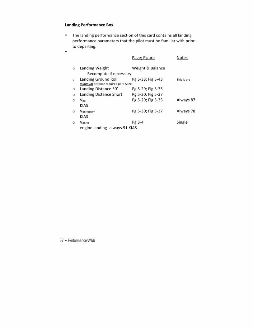
Landing Performance Box
• The landing performance section of this card contains all landing performance parameters that the pilot must be familiar with prior to departing.
• Page; Figure Notes
o Landing Weight Weight & Balance Recompute if necessary
o Landing Ground Roll Pg 5-‐33; Fig 5-‐43 This is the minimum distance required per FAR 91
o Landing Distance 50’ Pg 5-‐29; Fig 5-‐35 o Landing Distance Short Pg 5-‐30; Fig 5-‐37 o VREF Pg 5-‐29; Fig 5-‐35 Always 87
KIAS o VREFSHORT Pg 5-‐30; Fig 5-‐37 Always 78
KIAS o VREFSE Pg 3-‐4 Single
engine landing-‐ always 91 KIAS
38 • Oral Review
Rochester Air Center
SECTION 4
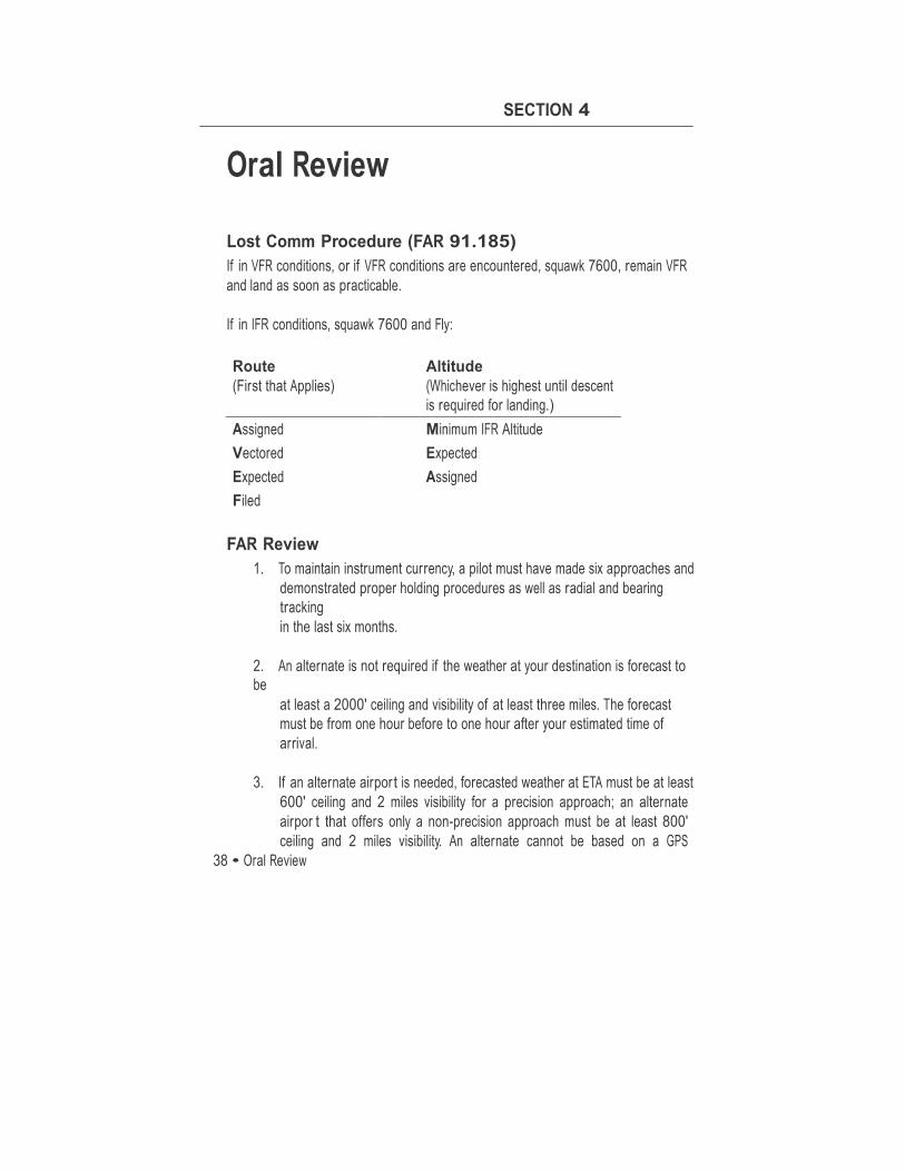
Oral Review Lost Comm Procedure (FAR 91.185) If in VFR conditions, or if VFR conditions are encountered, squawk 7600, remain VFR and land as soon as practicable.
If in IFR conditions, squawk 7600 and Fly:
Route (First that Applies)
Altitude (Whichever is highest until descent is required for landing.)
Assigned Minimum IFR Altitude Vectored Expected Expected Assigned Filed
FAR Review
1. To maintain instrument currency, a pilot must have made six approaches and demonstrated proper holding procedures as well as radial and bearing tracking in the last six months.
2. An alternate is not required if the weather at your destination is forecast to be
at least a 2000' ceiling and visibility of at least three miles. The forecast must be from one hour before to one hour after your estimated time of arrival.
3. If an alternate airpor t is needed, forecasted weather at ETA must be at least
600' ceiling and 2 miles visibility for a precision approach; an alternate airpor t that offers only a non-precision approach must be at least 800' ceiling and 2 miles visibility. An alternate cannot be based on a GPS
Oral Review • 39
Rochester Air Center
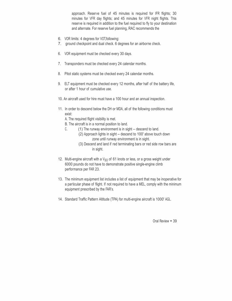
approach. Reserve fuel of 45 minutes is required for IFR flights; 30 minutes for VFR day flights; and 45 minutes for VFR night flights. This reserve is required in addition to the fuel required to fly to your destination and alternate. For reserve fuel planning, RAC recommends the
6. VOR limits: 4 degrees for VOT,following: 7. ground checkpoint and dual check. 6 degrees for an airborne check.
6. VOR equipment must be checked every 30 days.
7. Transponders must be checked every 24 calendar months.
8. Pitot static systems must be checked every 24 calendar months.
9. ELT equipment must be checked every 12 months, after half of the battery life,
or after 1 hour of cumulative use.
10. An aircraft used for hire must have a 100 hour and an annual inspection.
11. In order to descend below the DH or MDA, all of the following conditions must exist: A. The required flight visibility is met. B. The aircraft is in a normal position to land. C. (1) The runway environment is in sight – descend to land.
(2) Approach lights in sight – descend to 100' above touch down zone until runway environment is in sight.
(3) Descend and land if red terminating bars or red side row bars are in sight.
12. Multi-engine aircraft with a VSO of 61 knots or less, or a gross weight under
6000 pounds do not have to demonstrate positive single-engine climb performance per FAR 23.
13. The minimum equipment list includes a list of equipment that may be inoperative for
a par ticular phase of flight. If not required to have a MEL, comply with the minimum equipment prescribed by the FAR’s.
14. Standard Traffic Pattern Altitude (TPA) for multi-engine aircraft is 1000' AGL.
40 • Oral Review
Rochester Air Center
Answer The Following Sample Oral Questions Prior To Arriving For Training
1. Recite the V speeds.
2. What is the maximum demonstrated crosswind component?
3. Describe the Seneca II PA-34-200T engine. A. How many cylinders? B. Who is the manufacturer? C. What is the horsepower rating? D. Does it have fuel injectors or a carburetor? E. Is the engine turbo-charged or normally aspirated? F. Why is the right engine labeled TSILO-360? G. How are the cylinders arranged? H. How is ignition provided? I. What is the minimum and maximum oil capacities in the Seneca IIs?
4. Describe the propeller system. A. Who makes the propellers? B. What does oil pressure do to the propeller? C. Which lever manipulates oil pressure to the propeller? D. Which unit regulates oil pressure to the propeller? E. What is the function of the nitrogen cylinder? F. What is the purpose of the spring in the prop dome? G. Define constant speed. H. What unit adjusts the propeller to maintain a constant RPM
and how does it do it? I. Define full feathering.
J. Will the propeller always feather? K. What are centrifugal stop pins? L. What is the true purpose of the centrifugal stop pins?
5. What is the correct action for a propeller overspeed?
6. Describe the electrical system.
7. What are the indications of a failed alternator?
8. Will the engines continue to run with the alternator and battery master switches turned off?
Oral Review • 41
Rochester Air Center
9. Describe the vacuum system. A. Which instruments are vacuum operated? B. What are the normal vacuum operating limits? C. How many vacuum pumps does the PA-44 have? D. What indications would occur in the event of a vacuum pump failure?
10. Describe the stall warning system.
11. Describe the fuel system.
12. Explain how to cross feed fuel.
13. Describe the landing gear system. A. How is the landing gear actuated? Describe the pump. B. What keeps the gear in the up position? C. What keeps the gear in the down position? D. If Hydraulic pressure is suddenly lost in flight, what indication, if any, would you have? E. In what three situations will the landing gear horn activate? F. What unit will not allow the gear to be retracted on the ground? G. What is the procedure to extend the gear manually (Emergency Gear Extension)? H. What airspeed is of impor tance during manual gear extension? I. Are the brake and the landing gear hydraulics interconnected? J. If you lose gear hydraulics, will you still have brakes? K. What indicates that the gear is in transit and the hydraulic pump is activated?
14. What type of braking system is used by the Seneca II? Where is the brake fluid serviced?
15. What type of flaps does the Seneca II have? A. What are the flap settings on the Seneca II?
16. What are the maximum taxi, takeoff, and landing weights?
17. What is the maximum baggage capacity?
18. Define VSSE. 19. What are the drag factors on light twins?
20. Who determines VMC for a particular aircraft? 21. Define VMC. 22. Why is an aft CG used in determining VMC? 23. What are the factors in determining VMC? 24. Define critical engine and list the factors used to determine it.
42 • Oral Review
Rochester Air Center
25. What causes an aircraft to sideslip with the loss of an engine, and what action is required to correct this? 26. How much climb performance is lost when an engine fails?
27. What aircraft equipment checks are required under FAR par t 91?
28. Define absolute and single-engine service ceiling.
29. What documents are required to be on the aircraft?
30. Explain lost communications procedures.
31. Will the propeller feather below 800 RPM. Why or why not?
32. Explain the pitot static system. A. Does the PA-34 have an alternate static source? If so, how is it activated and what actions are necessary to acquire the most accurate reading? B. What instruments are pitot static? C. Where is the pitot static por t located?
33. How do you prevent a heater overheat?
34. What is the fuel capacity? How many gallons are unusable?
35. What grade fuel is to be used in the PA-34?
36. How many fuel pumps are on the aircraft?
37. When are the electric fuel pumps to be used?
38. What are the various positions on the fuel selector control?
39. Explain the procedure for cross feeding fuel when operating the right engine from the left tank.
40. If an engine failure occurred at 5000' MSL, or a high density altitude, what would you do to get max performance from the operating engine after performing the In-Flight Engine Failure Checklist?
41. If the cylinder head temp and oil temp approach the caution range, what can be done to assist in cooling?
42. Why does manifold pressure decrease approximately 1" every 1000' during climb?
43. When an engine is inoperative or feathered, what indication will be observed on the manifold pressure gauge?
44. Why is the manifold pressure gauge not necessarily a good indicator in determining an inoperative engine?

Oral Review • 43
Rochester Air Center