Embed Size (px)
Citation preview

Bob Gill, P.Eng., FEC.
Some text was taken from notes by Yaser M. Roshan
Introduction to Electro-Mechanical Sensors and Actuators
ENSC 387 (4)

ENSC 387
I IInstructor – Bob Gill P.Eng., FEC
Email: [email protected]
Office hours: in ASB 10855 Mon. & Wed. 10:30-12:30
Course Schedule:
Lecture:
Mon. 8:30-10:20
Wed. 8:30-9:20
Tutorial: Wed. 9:30-10:20
Final exam: TBD
WMC 3210
WMC 3210
WMC 3210

Course plan
Week Topic
1 Introduction, Control, and Instrumentation
2 Impedance Matching, Performance Analysis
3 Analog Sensors (potentiometer, variable inductance, tachometer)
4 Analog Sensors (variable capacitance, piezo sensor, strain gauge, accelerometer)
5 Analog Sensors (torque sensor, tactile sensor, optical and ultrasonic sensors,
thermofluid sensors )
6 Digital Sensors (shaft encoder, incremental encoder, absolute encoder)
7 Digital Sensors (digital tachometer, hall effect sensor)
8 Magnetic Circuits
9 Stepper motor (permanent magnet, variable reluctance)
10 AC Induction Motors
11 DC Motors
12 Synchronous Motors
13 Motor Speed Control

Laboratory
Problems with lab equipment:
Gary Houghton
Gary Shum
TAs: Gil Herrnstad
Lab. office hours:
Mon. 10:00-12:00 Lab01
Wed. 15:00-17:00 Lab01
Lab
No.
Subject Start Date End Date
1 Position and Velocity Sensors Jan Jan
2 Accelerometers Feb Feb
3 Strain Gauge for Poisson’s Ratio and Young’s Modulus Feb Feb
4 Stepper Motor Mar Mar
5 DC Motor Mar Mar

Laboratory Sign-‐Up Sheet
Coming Soon !!

Marks Distribution / Textbook
• Textbooks:• Sensors and Actuators: Control System Instrumentation,
Clarence W. de Silva, 2nd Edition, CRC Press• Principles of Electric Machines and Power Electronics, P. C.
Sen, 2nd Edition, John Wiley & Sons, 1996.
Component Percentage of Overall Mark
Assignments (4 of 5) 10 %
Laboratories (5 labs) 20 %
Midterm (1) 20 %
Final Exam 50 %

Assignments/Midterm
Assignment No. Available date Due date
1 TBA TBA
2 TBA TBA
3 TBA TBA
4 TBA TBA
5 TBA TBA
Midterm Tentative date (subject to change)
MT-Exam TBA

Control and Instrumentation
Signal conditioning/conversion: Based on different types and levels of signals in control systems.
Control System: Dynamic system that contains a controller.
Controller: Generate control signals to drive the process to becontrolled (the plant) in the desired manner.
Actuator: Perform control action.
Sensor/Transducer: Process responses of the system / monitoring / diagnosis

What is a Sensor ? Various Interpretations
A sensor is an object whose purpose is to detect events or changes in its environment, and then provide a corresponding output.
A sensor is a type of transducer; sensors may provide various types of output, but typically use electrical or optical signals.
Sensor - As the term suggests, it is a body which reacts to a physical, chemical or biological condition. It senses. It can be considered as a detector.
Check this site: http://what-is-a-sensor.com/

Analog and Digital SensorsAnalogue Sensors produce a continuous output signal or voltage which is generally proportional to the quantity being measured. Physical quantities such as Temperature, Speed, Pressure, Displacement, Strain etc are all analogue quantities as they tend to be continuous in nature. For example, the temperature of a liquid can be measured using a thermometer or thermocouple which continuously responds to temperature changes as the liquid is heated up or cooled down.
Digital Sensors produce a discrete digital output signals or voltages that are a digital representation of the quantity being measured. Digital sensors produce a Binary output signal in the form of a logic “1” or a logic “0”, (“ON” or “OFF”). This means then that a digital signal only produces discrete (non-continuous) values which may be outputted as a single “bit”, (serial transmission) or by combining the bits to produce a single “byte” output (parallel transmission).
Thermocouple used to produce an Analogue Signal
Light Sensor used to produce an Digital Signal

What is a Transducer ?A Transducer is more than a sensor. It consists of a sensor/actuator along with signal conditioning circuits.
A signal conditioning circuit, by the name is a circuit which conditions the signal so that it is strong enough for further processing. A system might contain many stages before the signal finally reaches its destination to derive meaningful information.

Common sensors and actuators in engineeringapplications
Process Typical Sensors Typical Actuators
Aircraft Displacement, speed, acceleration, elevation, force, pressure, temperature, GPS
DC motors, stepper motors, relays, valve actuators, pumps, heat sources, jet engines
Automobile Displacement, speed, force, pressure, temperature, fluid flow, fluid level, voltage, current
DC motors, stepper motors,valve actuators, pumps, heatsources
Home heating system Temperature, pressure, fluid flow Motors, pumps, heat sources
Milling machine Displacement, speed, force, temperature, voltage, current
DC motors, AC motors
Robot Optical image, displacement, speed, force, torque, voltage, current
DC motors, stepper motors, AC motors, hydraulic actuators
Wood Drying Kiln Temperature, relative humidity, moisture content, air flow
AC motors, DC motors, pumps, heat sources

Sensors in a Home

Sensors in a Home Cont’d

Sensors for Body

Sensors on an Automobile

Sensors on an Automobile Cont’d

Sensors in a Plane

There are certain features which have to be considered when wechoose a sensor. They are as given below:
Accuracy
Environmental condition.
usually has limits for temperature/ humidity
Range
Measurement limit of sensor
Calibration
Essential for most of the measuring devices as the readings changeswith time
Resolution
Smallest increment detected by the sensor
Cost
Repeatability
The reading that varies is repeatedly measured under the sameenvironment
Criteria to choose a Sensor

GOOD control system
• Sufficiently stable response
• Sufficiently fast response
• Low sensitivity to noise and other variations
• High sensitivity to control inputs
• Low error
• Reduced coupling among system variables
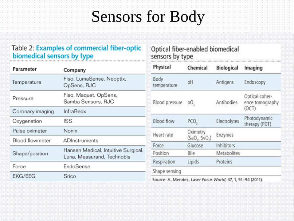
Control system types
• Open loop control
• Feedback control
o On/Off (bang-‐bang)
o Proportional
o PID : A proportional–integral–
derivative controller (PID controller) is a control loop feedback mechanism (controller) commonly used in industrial control systems. A PID controller continuously calculates an error value as the difference between a measured process variable and a desired set point.

• Digital control
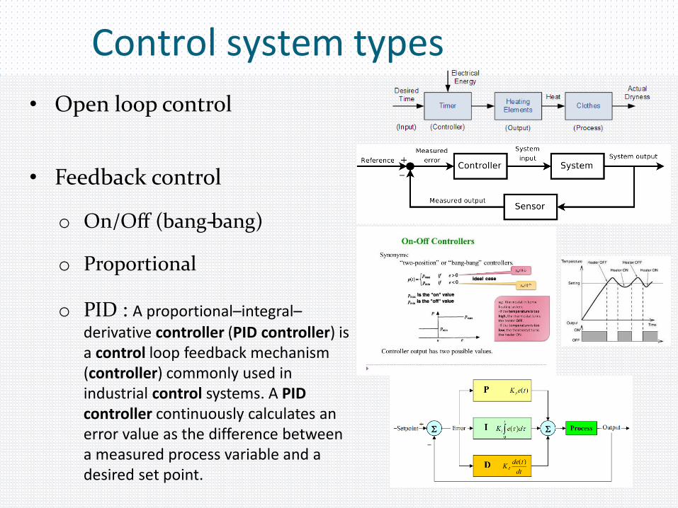
• Feed-‐forward control
Control system types .. Cont’d
Feed-‐forward system example

Example 1:Consider the system shown below:

Example 1 (Cont’d): Obtain the transfer function relationship between the output y and the
driving input u in the absence of disturbance input w.
Show that in the absence of u, the block diagram can be drawn as below.
Obtain the transfer function relationship between y and w in this case.
From previous sections, write an expression for y in terms of u and w.
Show that the effect of disturbance is fully compensated if the feed-‐forward
compensator is given by
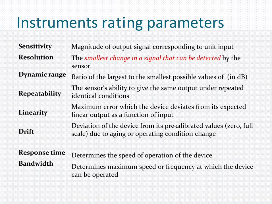
Instruments rating parametersSensitivity
Resolution
Magnitude of output signal corresponding to unit input
The smallest change in a signal that can be detected by the sensor
Ratio of the largest to the smallest possible values of (in dB)
The sensor’s ability to give the same output under repeated identical conditions
Maximum error which the device deviates from its expected linear output as a function of input
Deviation of the device from its pre-‐calibrated values (zero, full scale) due to aging or operating condition change
Determines the speed of operation of the device
Determines maximum speed or frequency at which the device can be operated
Dynamic range
Repeatability
Linearity
Drift
Response time
Bandwidth

Example 2: Confusion made complicated
Consider an instrument with a 12 bit Analog-‐to-‐ Digital converter (ADC).
Estimate the dynamic range of the instrument.
Hint: Find the resolution and minimum value then use the following formula for the dynamic range
𝐷𝑦𝑛𝑎𝑚𝑖𝑐 𝑅𝑎𝑛𝑔𝑒 = 20 log10𝑀𝑎𝑥𝑖𝑚𝑢𝑚 𝐻𝑖𝑔ℎ𝑒𝑠𝑡 𝑉𝑎𝑙𝑢𝑒 (𝑅𝑎𝑛𝑔𝑒 𝑜𝑓 𝑂𝑝𝑒𝑟𝑎𝑡𝑖𝑜𝑛)
𝑀𝑖𝑛𝑖𝑚𝑢𝑚 𝐷𝑒𝑡𝑒𝑐𝑡𝑎𝑏𝑙𝑒 𝑉𝑎𝑙𝑢𝑒 (𝑅𝑒𝑠𝑜𝑙𝑢𝑡𝑖𝑜𝑛)
Calculations: Need more information about the operating Range first. • The dynamic range is the ratio of the maximum voltage to the minimum voltage that the
ADC can convert. The maximum voltage is 5 volts. Since it is a 12 bit converter, it has a resolution of 212 - 1 or 4095. Thus the minimum voltage, for which the ADC would have only the least significant bit (or Min Detectable Value), is 1.22 millivolts. So the dynamic range of your ADC is 5/.00122 = 4095 = 72.2 dB
• In general, the dynamic range is only a function of the number of bits, not the maximum input voltage. We could have calculated DR as 6.02N = 6.02*12 = 72.24 dB
• 𝐷𝑦𝑛𝑎𝑚𝑖𝑐 𝑅𝑎𝑛𝑔𝑒 = 20 log10212−1−0
20−0= 72.2 dB

Impedance matching Definitions
Output impedance
Input impedance

Impedance matching Cascaded devices

Impedance matching
25V
Rs
RL
20mA
VL= 15V
Loading effect
Modulation
Use Modulating Signal to change a property of a CarrierSignal.
Amplitude Modulation
Frequency Modulation
Pulse Width Modulation
Etc.
De-Modulation


Modulation Schemes AM FM & PM

Pulse Width Modulation

De-Modulation