Embed Size (px)
Citation preview

INTRODUCTION TO MICROPROCESSORS
Richa Upadhyay Prabhu
NMIMS’s MPSTME
January 7, 2016
Richa Upadhyay Prabhu (MPSTME) INTRODUCTION January 7, 2016 1 / 63
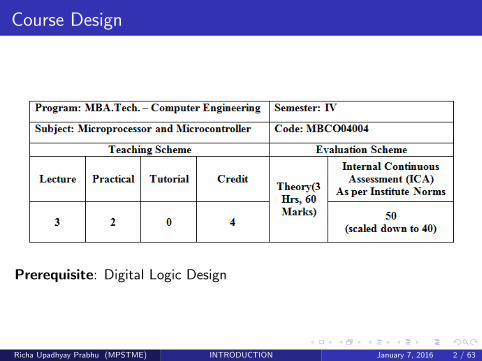
Course Design
Prerequisite: Digital Logic Design
Richa Upadhyay Prabhu (MPSTME) INTRODUCTION January 7, 2016 2 / 63
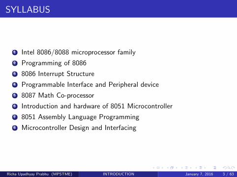
SYLLABUS
1 Intel 8086/8088 microprocessor family
2 Programming of 8086
3 8086 Interrupt Structure
4 Programmable Interface and Peripheral device
5 8087 Math Co-processor
6 Introduction and hardware of 8051 Microcontroller
7 8051 Assembly Language Programming
8 Microcontroller Design and Interfacing
Richa Upadhyay Prabhu (MPSTME) INTRODUCTION January 7, 2016 3 / 63
Books
1 Douglas Hall,(2006) ”Microprocessors Interfacing and Programming”,Tata McGraw Hill Publication.
2 Muhammad Ali Mazidi, (2011) ”Microcontroller and Embeddedsystem”, Second Edition Prentice Hall.
Richa Upadhyay Prabhu (MPSTME) INTRODUCTION January 7, 2016 4 / 63
Let’s Begin
Richa Upadhyay Prabhu (MPSTME) INTRODUCTION January 7, 2016 5 / 63
COMPUTERS
What are the Types of Computers?
Richa Upadhyay Prabhu (MPSTME) INTRODUCTION January 7, 2016 6 / 63
COMPUTERS
Types of Computers
Mainframes
Minicomputers
Microcomputers
Richa Upadhyay Prabhu (MPSTME) INTRODUCTION January 7, 2016 7 / 63
COMPUTERS
MAINFRAMESLargest, Fastest and most powerful
Massive memory
64 bit data words
uses:military defence controlcreating computer graphics for science fiction machine
Richa Upadhyay Prabhu (MPSTME) INTRODUCTION January 7, 2016 8 / 63
COMPUTERS
MINICOMPUTERSScaled down versions of Mainframe
small data words i.e 32 bits
lesser memory as compared to mainframes
uses:scientific researchindustrial control for eg. oil refinery
Richa Upadhyay Prabhu (MPSTME) INTRODUCTION January 7, 2016 9 / 63
COMPUTERS
MICROCOMPUTERSsmall computers
4 bit data word
can address thousands of bytes of memory with 64 bit address word
CPU is single IC called MICROPROCESSORS
Used in everything from smart sewing machines to CAD systems
Richa Upadhyay Prabhu (MPSTME) INTRODUCTION January 7, 2016 10 / 63
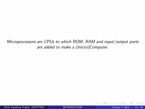
Microprocessors are CPUs to which ROM, RAM and input/output portsare added to make a (micro)Computer.
Richa Upadhyay Prabhu (MPSTME) INTRODUCTION January 7, 2016 11 / 63
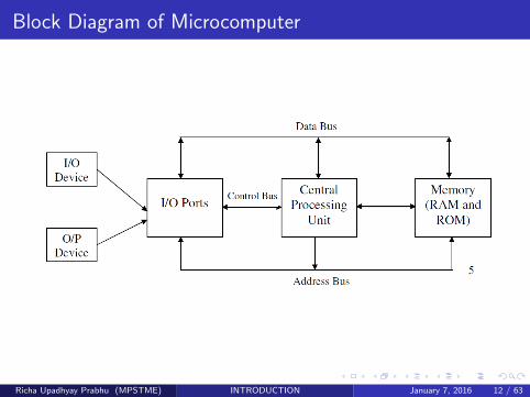
Block Diagram of Microcomputer
Richa Upadhyay Prabhu (MPSTME) INTRODUCTION January 7, 2016 12 / 63
Block Diagram of Microcomputer
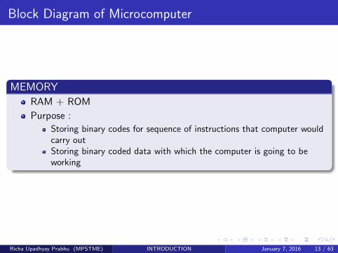
MEMORYRAM + ROM
Purpose :Storing binary codes for sequence of instructions that computer wouldcarry outStoring binary coded data with which the computer is going to beworking
Richa Upadhyay Prabhu (MPSTME) INTRODUCTION January 7, 2016 13 / 63

Block Diagram of Microcomputer
INPUT/OUTPUT
Allows computer and user to interact with each other
I/O ports are simply set of parallel D - flipflop
Data is transferred from/to latches when they are enabled by acontrol signal by CPU
Richa Upadhyay Prabhu (MPSTME) INTRODUCTION January 7, 2016 14 / 63
Block Diagram of Microcomputer
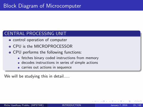
CENTRAL PROCESSING UNITcontrol operation of computer
CPU is the MICROPROCESSOR
CPU performs the following functions:fetches binary coded instructions from memorydecodes instructions in series of simple actionscarries out actions in sequence
We will be studying this in detail.....
Richa Upadhyay Prabhu (MPSTME) INTRODUCTION January 7, 2016 15 / 63
Block Diagram of Microcomputer
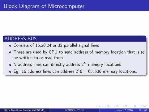
ADDRESS BUSConsists of 16,20,24 or 32 parallel signal lines
These are used by CPU to send address of memory location that is tobe written to or read from
N address lines can directly address 2N memory locations
Eg: 16 address lines can address 216 = 65, 536 memory locations.
Richa Upadhyay Prabhu (MPSTME) INTRODUCTION January 7, 2016 16 / 63
Block Diagram of Microcomputer
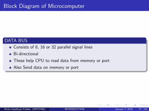
DATA BUSConsists of 8, 16 or 32 parallel signal lines
Bi-directional
These help CPU to read data from memory or port
Also Send data on memory or port
Richa Upadhyay Prabhu (MPSTME) INTRODUCTION January 7, 2016 17 / 63
Block Diagram of Microcomputer
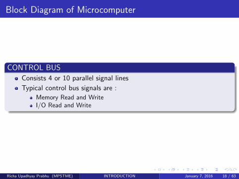
CONTROL BUSConsists 4 or 10 parallel signal lines
Typical control bus signals are :Memory Read and WriteI/O Read and Write
Richa Upadhyay Prabhu (MPSTME) INTRODUCTION January 7, 2016 18 / 63
OUR CONCERN IS ONLY WITH THE CPU i.e.MICROPROCESSOR
Richa Upadhyay Prabhu (MPSTME) INTRODUCTION January 7, 2016 19 / 63
EVOLUTION OF MICROPROCESSOR
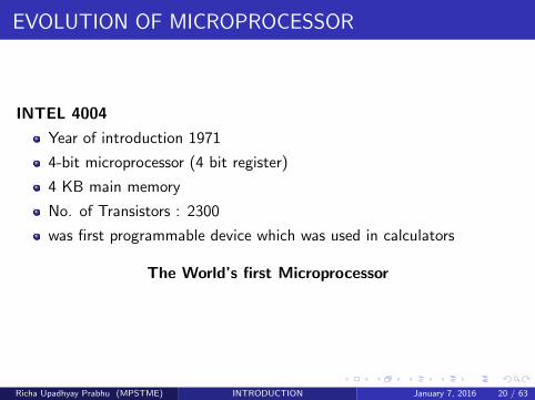
INTEL 4004
Year of introduction 1971
4-bit microprocessor (4 bit register)
4 KB main memory
No. of Transistors : 2300
was first programmable device which was used in calculators
The World’s first Microprocessor
Richa Upadhyay Prabhu (MPSTME) INTRODUCTION January 7, 2016 20 / 63
EVOLUTION OF MICROPROCESSOR
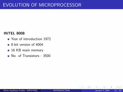
INTEL 8008
Year of introduction 1972
8-bit version of 4004
16 KB main memory
No. of Transistors : 3500
Richa Upadhyay Prabhu (MPSTME) INTRODUCTION January 7, 2016 21 / 63
EVOLUTION OF MICROPROCESSOR
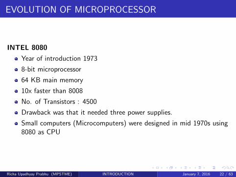
INTEL 8080
Year of introduction 1973
8-bit microprocessor
64 KB main memory
10x faster than 8008
No. of Transistors : 4500
Drawback was that it needed three power supplies.
Small computers (Microcomputers) were designed in mid 1970s using8080 as CPU
Richa Upadhyay Prabhu (MPSTME) INTRODUCTION January 7, 2016 22 / 63
EVOLUTION OF MICROPROCESSOR
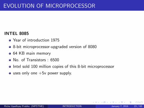
INTEL 8085
Year of introduction 1975
8-bit microprocessor-upgraded version of 8080
64 KB main memory
No. of Transistors : 6500
Intel sold 100 million copies of this 8-bit microprocessor
uses only one +5v power supply.
Richa Upadhyay Prabhu (MPSTME) INTRODUCTION January 7, 2016 23 / 63
EVOLUTION OF MICROPROCESSOR
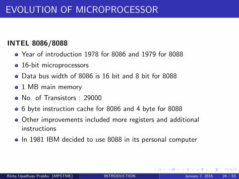
INTEL 8086/8088
Year of introduction 1978 for 8086 and 1979 for 8088
16-bit microprocessors
Data bus width of 8086 is 16 bit and 8 bit for 8088
1 MB main memory
No. of Transistors : 29000
6 byte instruction cache for 8086 and 4 byte for 8088
Other improvements included more registers and additionalinstructions
In 1981 IBM decided to use 8088 in its personal computer
Richa Upadhyay Prabhu (MPSTME) INTRODUCTION January 7, 2016 24 / 63
EVOLUTION OF MICROPROCESSOR
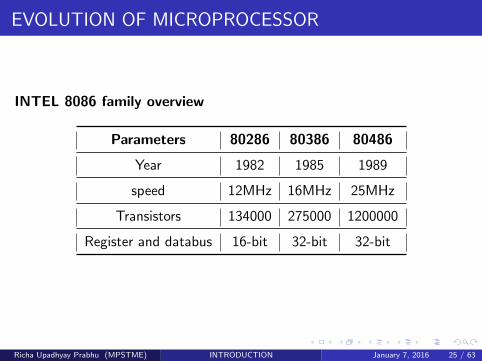
INTEL 8086 family overview
Parameters 80286 80386 80486
Year 1982 1985 1989
speed 12MHz 16MHz 25MHz
Transistors 134000 275000 1200000
Register and databus 16-bit 32-bit 32-bit
Richa Upadhyay Prabhu (MPSTME) INTRODUCTION January 7, 2016 25 / 63
EVOLUTION OF MICROPROCESSOR
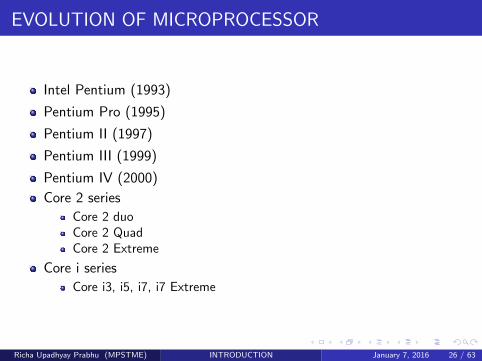
Intel Pentium (1993)
Pentium Pro (1995)
Pentium II (1997)
Pentium III (1999)
Pentium IV (2000)
Core 2 seriesCore 2 duoCore 2 QuadCore 2 Extreme
Core i seriesCore i3, i5, i7, i7 Extreme
Richa Upadhyay Prabhu (MPSTME) INTRODUCTION January 7, 2016 26 / 63
FEATURES OF 8086
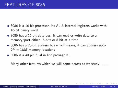
8086 is a 16-bit processor. Its ALU, internal registers works with16-bit binary word
8086 has a 16-bit data bus. It can read or write data to amemory/port either 16-bits or 8 bit at a time
8086 has a 20-bit address bus which means, it can address upto220 = 1MB memory locations
8086 is a 40 pin dual in line package IC
Many other features which we will come across as we study ........
Richa Upadhyay Prabhu (MPSTME) INTRODUCTION January 7, 2016 27 / 63
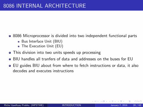
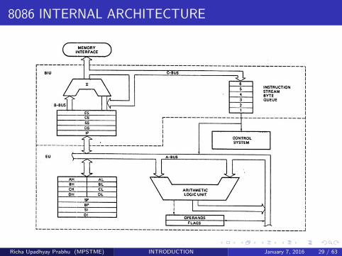
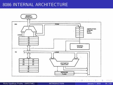
8086 INTERNAL ARCHITECTURE
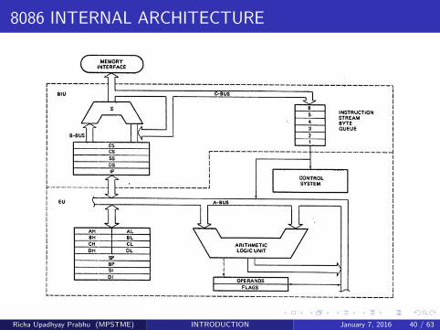
8086 Microprocessor is divided into two independent functional partsBus Interface Unit (BIU)The Execution Unit (EU)
This division into two units speeds up processing
BIU handles all tranfers of data and addresses on the buses for EU
EU guides BIU about from where to fetch instructions or data, it alsodecodes and executes instructions
Richa Upadhyay Prabhu (MPSTME) INTRODUCTION January 7, 2016 28 / 63
8086 INTERNAL ARCHITECTURE
Richa Upadhyay Prabhu (MPSTME) INTRODUCTION January 7, 2016 29 / 63
EXECUTION UNIT
CONTROL CIRCUITRY
directs internal operations
INSTRUCTION DECODER
translates the instructions fetched from memory into series ofoperations which the EU performs
ALU
16 bit arithmetic logic unit which can add, subtract, AND, OR, XOR,increment, decrement, complement, shift binary numbers etc.
Richa Upadhyay Prabhu (MPSTME) INTRODUCTION January 7, 2016 30 / 63

8086 INTERNAL ARCHITECTURE
Richa Upadhyay Prabhu (MPSTME) INTRODUCTION January 7, 2016 31 / 63
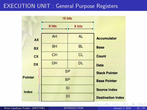
EXECUTION UNIT : General Purpose Registers
Richa Upadhyay Prabhu (MPSTME) INTRODUCTION January 7, 2016 32 / 63
EXECUTION UNIT : General Purpose Registers
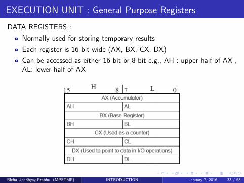
DATA REGISTERS :
Normally used for storing temporary results
Each register is 16 bit wide (AX, BX, CX, DX)
Can be accessed as either 16 bit or 8 bit e.g., AH : upper half of AX ,AL: lower half of AX
Richa Upadhyay Prabhu (MPSTME) INTRODUCTION January 7, 2016 33 / 63
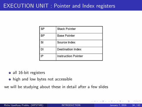
EXECUTION UNIT : Pointer and Index registers
all 16-bit registers
high and low bytes not accessible
we will be studying about these in detail after a few slides
Richa Upadhyay Prabhu (MPSTME) INTRODUCTION January 7, 2016 34 / 63
8086 INTERNAL ARCHITECTURE
Richa Upadhyay Prabhu (MPSTME) INTRODUCTION January 7, 2016 35 / 63
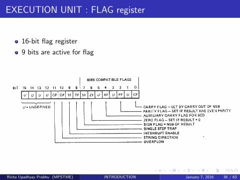
EXECUTION UNIT : FLAG register
16-bit flag register
9 bits are active for flag
Richa Upadhyay Prabhu (MPSTME) INTRODUCTION January 7, 2016 36 / 63
EXECUTION UNIT : FLAG register
These 9 Flags are divided into two typesConditional FlagsControl Flags
Richa Upadhyay Prabhu (MPSTME) INTRODUCTION January 7, 2016 37 / 63
EXECUTION UNIT : FLAG register
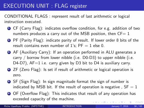
CONDITIONAL FLAGS : represent result of last arithmetic or logicalinstruction executed.
1 CF (Carry Flag): indicates overflow condition, for e.g. addition of twonumbers produces a carry out of the MSB position, then CF= 1
2 PF (Parity Flag): indicate parity of result. If lower order 8 bits of theresult contains even number of 1’s; PF = 1 else 0.
3 AF (Auxiliary Carry): If an operation performed in ALU generates acarry / borrow from lower nibble (i.e. D0-D3) to upper nibble (i.e.D4-D7), AF=1 i.e. carry given by D3 bit to D4 is auxiliary carry.
4 ZF (Zero Flag): Is set if result of arithmetic or logical operation iszero.
5 SF (Sign Flag): In sign magnitude format the sign of number isindicated by MSB bit. If the result of operation is negative , SF = 1
6 OF (Overflow Flag): This indicates that result of any operation hasexceeded capacity of the machine.
Richa Upadhyay Prabhu (MPSTME) INTRODUCTION January 7, 2016 38 / 63
EXECUTION UNIT : FLAG register
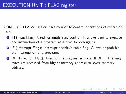
CONTROL FLAGS : set or reset by user to control operations of executionunit.
1 TF(Trap Flag): Used for single step control. It allows user to executeone instruction of a program at a time for debugging.
2 IF (Interrupt Flag): Interrupt enable/disable flag. Allows or prohibitthe interruption of a program.
3 DF (Direction Flag): Used with string instructions. If DF = 1; stringbytes are accessed from higher memory address to lower memoryaddress.
Richa Upadhyay Prabhu (MPSTME) INTRODUCTION January 7, 2016 39 / 63
8086 INTERNAL ARCHITECTURE
Richa Upadhyay Prabhu (MPSTME) INTRODUCTION January 7, 2016 40 / 63
BUS INTERFACE UNIT
Contains:
6- byte Instruction Queue
Segment Registers (CS, DS, ES, SS)
Instruction Pointer
Address Summing Block
Richa Upadhyay Prabhu (MPSTME) INTRODUCTION January 7, 2016 41 / 63
BUS INTERFACE UNIT
QUEUE
The BIU uses a mechanism known as an instruction stream queueto implement a pipeline architecture.
Both units (EU and BIU) operate asynchronously to give the 8086 anoverlapping instruction fetch and execution mechanism which is calledas Pipelining. This results in e�cient use of the system bus andsystem performance.
This queue permits pre-fetch of up to 6 bytes of instruction code.
Whenever the queue of the BIU is not full and at the same time theEU is not requesting it to read or write operands from memory, theBIU is free to look ahead in the program by pre-fetching the nextsequential instruction.
Richa Upadhyay Prabhu (MPSTME) INTRODUCTION January 7, 2016 42 / 63
BUS INTERFACE UNIT
QUEUE
These pre-fetching instructions are held in its FIFO queue
The EU accesses the queue from the output end. It reads oneinstruction byte after the other from the output of the queue
The intervals of no bus activity, which may occur between bus cyclesare known as Idle state
Richa Upadhyay Prabhu (MPSTME) INTRODUCTION January 7, 2016 43 / 63
BUS INTERFACE UNIT
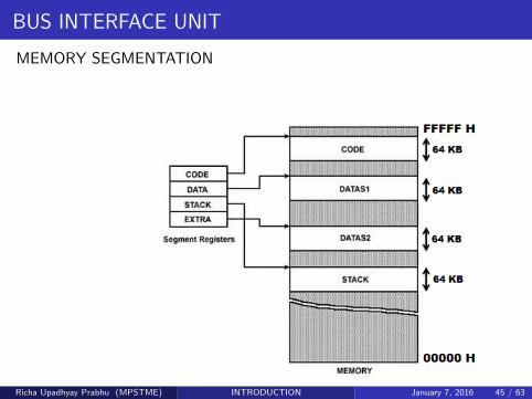
MEMORY SEGMENTATION
8086 is able to address 1Mbyte of memory (00000H - FFFFFH).TheComplete physically available memory may be divided into a numberof logical segments.
The memory in an 8086 based system is organized as segmentedmemory.
It is divided into 4 segments of 64KB each
The segments are :Code SegmentData SegmentStack SegmentExtra Segment
Richa Upadhyay Prabhu (MPSTME) INTRODUCTION January 7, 2016 44 / 63
BUS INTERFACE UNIT
MEMORY SEGMENTATION
Richa Upadhyay Prabhu (MPSTME) INTRODUCTION January 7, 2016 45 / 63
BUS INTERFACE UNIT
MEMORY SEGMENTATION
A segment may be located any where in the memory
Each of these segments can be used for a specific function.Code segment is used for storing the instructionsThe stack segment is used as a stack and it is used to store the returnaddressesThe data and extra segments are used for storing data byte.
Segments may be overlapped or non-overlapped.
In assembly language programming more than one Code/Data/Stacksegments can be defined. But only one segment of each type can beaccessed at a time.
Richa Upadhyay Prabhu (MPSTME) INTRODUCTION January 7, 2016 46 / 63
BUS INTERFACE UNIT
SEGMENT REGISTERS
BIU has FOUR 16-bit segment registers. They are:
1 Code Segment Register (CS)
2 Data Segment Register (DS)
3 Stack Segment Register (SS)
4 Extra Segment Register (ES)
Segment registers hold upper 16 bits of starting address of four
corresponding memory segments.
Each segment register is 16-bit long, so can access 216 = 64 KBytes
of memory.
Richa Upadhyay Prabhu (MPSTME) INTRODUCTION January 7, 2016 47 / 63
BUS INTERFACE UNIT
MEMORY SEGMENTATION
Richa Upadhyay Prabhu (MPSTME) INTRODUCTION January 7, 2016 48 / 63
INSTRUCTION POINTER (IP)
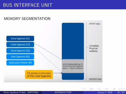
Code segment Register (CS) holds what ???
The IP is a register that holds 16-bit address of the next code bytewithin this code segment.
It is incremented automatically, depending on the no. of bytes theinstruction has
Contents of the Instruction Pointer are used for 20 bit memoryaddress calculation.
It is also known as O↵set Address. O↵set is the displacement of thememory location from the starting location of the segment.
IP contains distance or o↵set from base address to the next instruction byte to be
fetched.
Richa Upadhyay Prabhu (MPSTME) INTRODUCTION January 7, 2016 49 / 63
CALCULATION OF ADDRESS
How is a 20-bit address obtained if there are only 16-bit registers?
The 20-bit address of a byte is called its Physical Address.
But, it is specified as a Logical Address
Logical address is in the form of: Base Address : O↵set
Richa Upadhyay Prabhu (MPSTME) INTRODUCTION January 7, 2016 50 / 63
What is Base Address?
It is 20-bit starting address of any segment
To get 20- bit Base address of a segment, 0 H (or 0000) is appendedat the lower bit.
For eg: if CS = 1234 H, To convert this 16-bit address into 20-bit,the BIU appends 0H to the LSBs of the address.
After appending, the starting address of the Code Segment becomes12340H.
Richa Upadhyay Prabhu (MPSTME) INTRODUCTION January 7, 2016 51 / 63
CALCULATION OF PHYSICAL/EFFECTIVE ADDRESS
How is a 20-bit address obtained if there are only 16-bit registers?
To calculate the physical address of the memory, BIU uses thefollowing formula
Physical Address = Starting Address of Segment (Base Address) +O↵set (content of IP)
To find the starting address of the segment, BIU appends the contentsof Segment Register with 0H.Then, it adds o↵set to it.
Richa Upadhyay Prabhu (MPSTME) INTRODUCTION January 7, 2016 52 / 63
CALCULATION OF PHYSICAL/EFFECTIVE ADDRESS
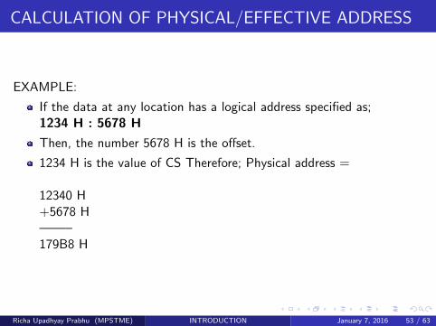
EXAMPLE:
If the data at any location has a logical address specified as;1234 H : 5678 H
Then, the number 5678 H is the o↵set.
1234 H is the value of CS Therefore; Physical address =
12340 H+5678 H——–179B8 H
Richa Upadhyay Prabhu (MPSTME) INTRODUCTION January 7, 2016 53 / 63
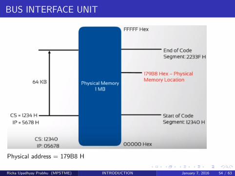
BUS INTERFACE UNIT
Physical address = 179B8 H
Richa Upadhyay Prabhu (MPSTME) INTRODUCTION January 7, 2016 54 / 63
STACK
STACK SEGMENT : Section of 64 Kbyte memory to store addresses anddata while a subprogram is executing.
STACK SEGMENT REGISTER : Upper 16-bits of the stack segment arestored in Stack Segment Register (SS).
STACK POINTER :
Is in the Execution Unit
16-bit o↵set from start of the segment to the memory location wherea word was last stored.
Same as Instruction Pointer
Richa Upadhyay Prabhu (MPSTME) INTRODUCTION January 7, 2016 55 / 63
OTHER POINTER AND INDEX REGISTERS
EU has four 16-bit pointer and index registers:
Stack Pointer
Base Pointer
Source Index
Destination Index
They hold 16-bit o↵set of a data word in one of the segment.For example: SI store o↵set of data word for Data segment.
Richa Upadhyay Prabhu (MPSTME) INTRODUCTION January 7, 2016 56 / 63
This was all about the Internal Architecture of 8086 .
Let’s have a look at the addressing modes of 8086 .
Richa Upadhyay Prabhu (MPSTME) INTRODUCTION January 7, 2016 57 / 63
ADDRESSING MODES
The addressing modes describe the types of operands and the way they areaccessed for executing an instruction.
IMMEDIATE ADDRESSING:
In this type of addressing, immediate data is a part of instruction, andappears in the form of successive byte or bytes.
Example: MOV AX, 0005H
In the above example, 0005H is the immediate data. The immediatedata may be 8-bit or 16-bit in size
Richa Upadhyay Prabhu (MPSTME) INTRODUCTION January 7, 2016 58 / 63
ADDRESSING MODES
DIRECT ADDRESSING:
In the direct addressing mode, a 16-bit memory address (o↵set) isdirectly specified in the instruction as a part of it.
Example: MOV AX, [5000H]
Here, data resides in a memory location in the data segment, whosee↵ective address may be computed using 5000H as the o↵set addressand content of DS as segment address.
Richa Upadhyay Prabhu (MPSTME) INTRODUCTION January 7, 2016 59 / 63
ADDRESSING MODES
REGISTER ADDRESSING:
In register addressing mode, the data is stored in a register and it isreferred using the particular register. All the registers, except IP, maybe used in this mode.
Example: MOV BX, AX.
Richa Upadhyay Prabhu (MPSTME) INTRODUCTION January 7, 2016 60 / 63
ADDRESSING MODES
REGISTER INDIRECT ADDRESSING:
the address of the memory location, which contains data or operand,is determined in an indirect way, using the o↵set registers.
the o↵set address of data is in either BX or SI or DI registers. Thedefault segment is either DS or ES.
The data is supposed to be available at the address pointed to by thecontent of any of the above registers in the default data segment.
Example: MOV AX, [BX]
Here, data is present in a memory location in DS whose o↵set addressis in BX.
Richa Upadhyay Prabhu (MPSTME) INTRODUCTION January 7, 2016 61 / 63
ADDRESSING MODES
REGISTER RELATIVE ADDRESSING:
the data is available at an e↵ective address formed by adding an 8-bitor 16-bit displacement with the content of any one of the registersBX, BP, SI and DI in the default (either DS or ES) segment.
Example: MOV Ax, 50H [BX]
Here, e↵ective address is given as 10H x DS + 50H + [BX]
Richa Upadhyay Prabhu (MPSTME) INTRODUCTION January 7, 2016 62 / 63
ASSIGNMENT - 1
Study of Instruction setPrepare a document of all the Instructions of 8086 along with their shortdescription.NOTE:
This can be a hand written document or a soft copy.
Refer any book, internet , anything
To be submitted on 11-01-2016, Monday
Richa Upadhyay Prabhu (MPSTME) INTRODUCTION January 7, 2016 63 / 63