Embed Size (px)
Citation preview

Introduction to VHDL
Yvonne AvilésColaboration: Irvin Ortiz Flores
Rapid System Prototyping Laboratory (RASP)University of Puerto Rico at Mayaguez
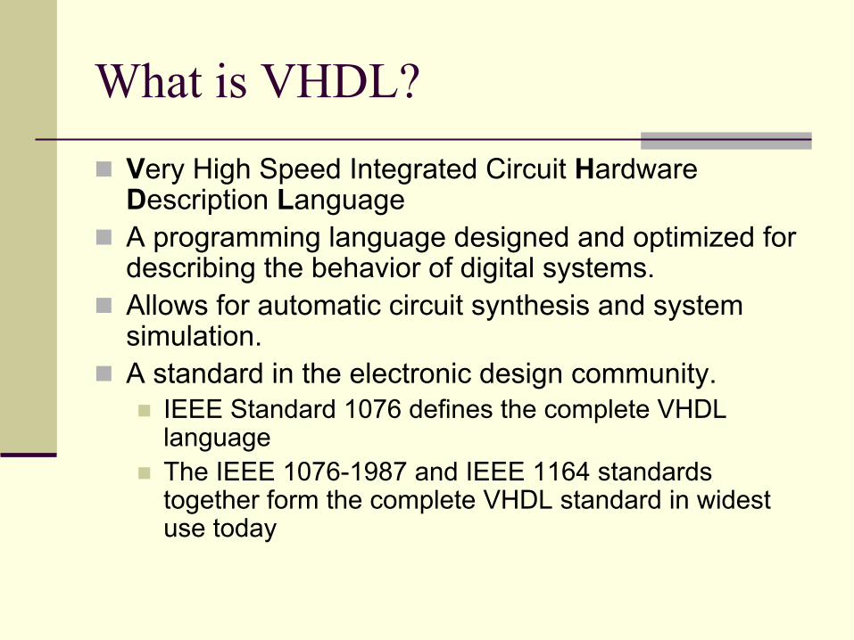
What is VHDL?Very High Speed Integrated Circuit Hardware Description LanguageA programming language designed and optimized for describing the behavior of digital systems.Allows for automatic circuit synthesis and system simulation. A standard in the electronic design community.
IEEE Standard 1076 defines the complete VHDL language The IEEE 1076-1987 and IEEE 1164 standards together form the complete VHDL standard in widest use today

Entities and Architectures
Every VHDL design description consists of at least one entity/architecture pair.A VHDL entity is a statement that defines the external specification of a circuit or sub-circuit.Provides the complete interface for a circuit
Names, data types, direction of ports
entity compare isport( A, B: in bit_vector(0 to 7);
EQ: out bit);end compare;

Architecture DeclarationEvery referenced entity in a VHDL design description must be bound with a corresponding architecture. The architecture describes the actual function—or contents—of the entity to which it is bound.
architecture compare1 of compare isbegin
EQ <= ‘1’ when (A = B) else ‘0’;end compare1;
Hierarchy and subprogram features of the language allow lower-level components, subroutines and functions in architectures; a process allows complex registered sequential logic as well. VHDL allows more than one alternate architecture for an entity.

VHDL Architecture Structure
architecture name_arch of entity is
begin
end name_arch;
Signal assignments
Concurrent statements
Concurrent statements
Process 1
Process 2
Concurrent statements
Processes contain sequentialstatements, but executeconcurrently within the
architecture body

VHDL Process Syntax
P1: process (<sensitivity list>)<variable declarations>begin
<sequential statements>end process P1;
Within a process: Variables are assigned using := and are updated immediately. Signals are assigned using <= and are updated at the end of the process.
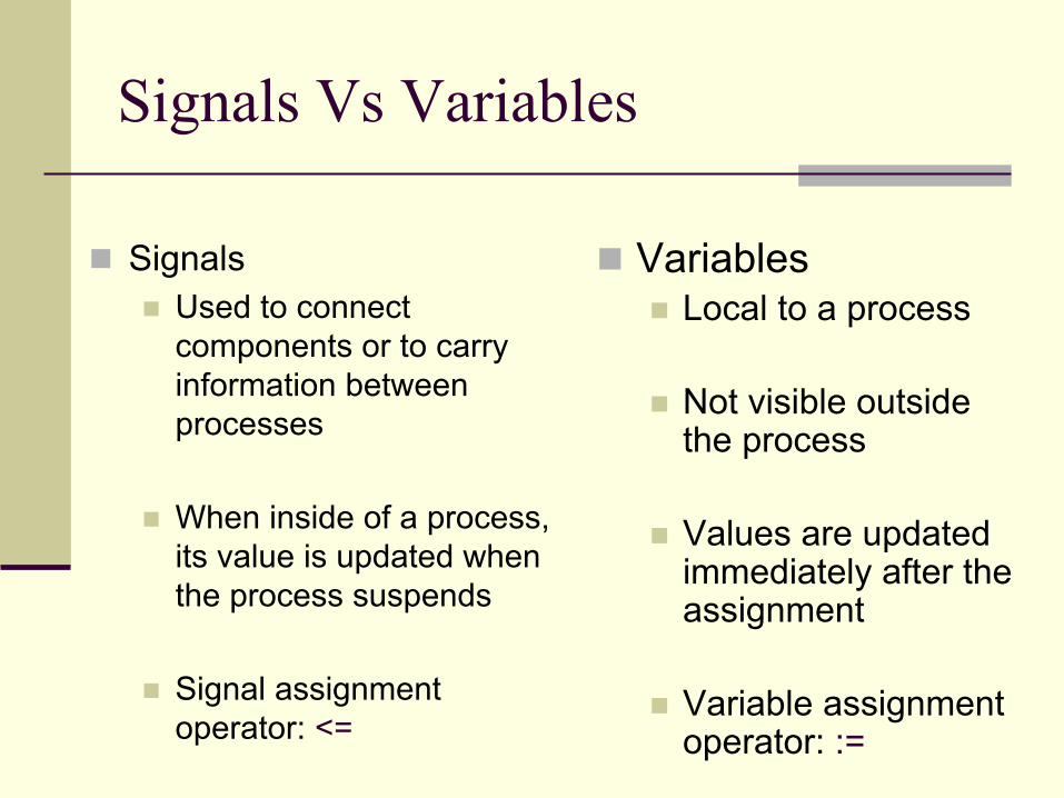
Signals Vs Variables
SignalsUsed to connect components or to carry information between processes
When inside of a process, its value is updated when the process suspends
Signal assignment operator: <=
VariablesLocal to a process
Not visible outside the process
Values are updated immediately after the assignment
Variable assignment operator: :=

Signals Vs Variables
SignalsInitial values: A=5, X=10, B=15Final values: A=10, B=5
Sigproc: process(A,X)
BeginA <= X;B <= A;
End process Sigproc;
VariablesInitial values: X=10Final values: A=10, B=10
Sigproc: process(X)Variable A,B : integer;
BeginA := X;B := A;
End process Sigproc;

Data TypesLike a high-level software programming language, data is represented in terms of high-level data types.Every data type in VHDL has a defined set of values and valid operations.
Data Type Values Example
Bit ‘1’,‘0’ Q<=‘1’;Bit_vector (array of bits) DataOut <= "00010101";Boolean True, False EQ <= True;Integer -2, -1, 0, 1, 2, 3, 4 . . . Count <= Count + 2; Real 1.0, -1.0E5 V1 = V2 / 5.3Time 1 ua, 7 ns, 100 ps Q <= ‘1’ after 6 ns;Character ‘a’, ‘b’, ‘2, ‘$’, etc. CharData <= ‘X’;String (Array of characters) Msg <= "MEM: " & Addr

Design Units
Entity : Interface Architecture : Implementation, behavior, function Configuration : Model chaining, structure, hierarchy Process : Concurrency, event controlled Package : Modular design, standard solution, data types, constants Library : Compilation, object code

Levels of AbstractionBehavior
Relies on processes to implement sequentialstatements
DataflowDescribe circuit in terms of how data moves through the system.Also referred to as register transfer logic, or RTL.
StructureUsed to describe a circuit in terms of its components Requires hierarchical constructs
Mixed MethodAny combination of methods

Entity Declaration
Specifies the unit' s ports
States the port's nametype, mode
Ports can be in, out orinout
Port size can be from a bit to a bit vector
Adder
A
Cin
B
Sum
Cout
Entity name
Port names Port mode Port type
Port length
Entity Adder isport (A,B : in std_logic(4 downto 0);
Cin : in std_logic;Sum : out std_logic(4 downto 0);
Cout : out std_logic);End Adder;

An Architecture Example
library IEEE;use IEEE.std_logic_1164.all;use IEEE.STD_LOGIC_ARITH.all;
Entity Adder isport (A,B : in std_logic_vector(4 downto 0);
Cin : in std_logic;Sum : out std_logic_vector(4 downto 0);
Cout : out std_logic);End Adder;
architecture a_adder of adder is
signal AC,BC,SC : std_logic_vector(5 downto 0);
beginAC <='0' & A;BC <='0' & B; SC <= unsigned(AC) + unsigned(BC) + Cin;Cout <= SC(5);Sout <= SC(4 downto 0);
end a_adder;
Concurrent Statements:Processedat the same time. Also componentinstantiations, and processes can be placed.
Signal declaration. Also can be placed component, constants, types, declarations.
Architecture declaration
Associated entity
Library declaration section

A “D” Flip-Flop
Explicit comparations and assigmentsto port and signals uses ‘ ’ for one bit and “ ” for multiple bits
Refers to the rising edge of the clock
entity dff isport ( d,clock : in bit;
q: out bit);end dff;
architecture arch of dff isbegin
process (clock)begin
if(clock'event andclock=1) then
if(d=‘1’) thenq <= ‘1’;
elseq <= ‘0’;
end if;end if;
end process;end arch;

D Flip-Flop Behavioral--Active low preset and clear inputsentity dffpc2 is
port(d,clock,clrn,prn:in bit;q,qbar:out bit;
end dffpc2;
architecture arch of dffpc2 isbegin
process(clock,clrn,prn)beginif(clock’event and clock = ‘1’) then
q <= not prn or (clrn andd);
qbar <= prn and (not clrnor not d);
end if;end process;
end arch;

D Flip-Flop Dataflow--D flip-flop dataflow--Includes preset and clearentity dff_flow is
port (d, prn, clrn: in bit;q,qbar: out bit);
end dff_flow;
architecture archl of dff_flow isbegin
q <= not prn or (clrn and d);qbar <= prn and (not clrn or notd);
end archl;

D Flip-Flop Structural
--A two input nand gate entity nandtwo is
port(x, y:in bit;z :out bit);
end nandtwo;architecture anandtwo of nandtwoisbegin
z <= not(x and y);end anandtwo;
Component instantiation. Conections are made by correspondence
Componentdeclaration. Port appearsexactly as in the entitydeclaration.
Componentinstantiationlabel
Entity name
entity dff_str isport (d :in bit;
q,qbar:out bit);end dff_str;
architecture adff_str of dff_str iscomponent nandtwo
port(x, y: in bit;z:out bit);
end component;signal qbarinside, qinside, dbar: bit;begin
nandq:nandtwoport map(qinside, d,qbarinside);
nandqbar:nandtwoport map(qbarinside,dbar, qinside);
dbar <= not d;q <= qinside;qbar <= qbarinside;
end adff_str;
qinside
nandq:nandtwo
nandqbar:nandtwo
qbarinside
dbar
d qbar
q

Three-Bit Binary Counterentity countl is
port( clock, enable: in bit;qa: out integer range 0 to 7);
end countl;
architecture countarch of countl isbegin
process (clock)variable count: integer range 0 to 7;begin
if (clock’event and clock ='1') thenif enable = '1' then
count:=count + 1;end if;
end if;qa <= count after 10 ns;
end process;end countarch;
Sensitivity list. Process is executedeverytime one of this parameterschange.
Variable declaration
Sequential statements.
Variable assignment operator
Signal assignment operator

D Flip-Flop with Asynchronous Preset and Clear
Integer range definition. Range 0 to 1 defines one bit.
entity dffapc isport(clock, d, prn, clrn : in bit;
q : out bit);end dffapc;architecture archl of dffapc isbegin
process(clock, clrn, prn)variable reset, set: integer range 0 to1; begin
if(prn=‘0’) thenq <= ‘1’;
elsif (clrn=‘0’) thenq <= ‘0’;
elsif (clock’event andclock=‘1’) then
q <= d;end if;
end process;end archl;

Four Bit Adder
Integer type allows addition, subtraction and multiplication. Needthe following statement at the librarydeclaration section:
use IEEE.STD_LOGIC_ARITH.all
--A VHDL 4 bit adderentity fourbadd is
port (cin: in integer range 0 to 1;
addendl:in integer range 0 to 15;
addend2:in integer range 0 to 15;
sum: out integer range 0 to31);
end fourbadd;architecture a4bitadd of fourbadd isbegin
sum <= addendl + addend2 + cin; end a4bitadd;

Synthesis
Synthesis is a process of translating an abstract concept into a less-abstract form. The highest level of abstraction accepted by today’s synthesis tools is the dataflow level.

Display Driver
state_mach
fsm
clkreset
[1:0]stat[1:0]
bcd
conv
[3:0] inbcd[3:0] [6:0]outled[6:0]
mux
selector
[3:0] digit0[3:0][3:0] digit2[3:0][3:0] digit1[3:0][3:0] digit3[3:0][1:0] selec[1:0]
[3:0]muxout[3:0] datout[6:0][6:0]
selec[1:0][1:0]
resetclk
d3[3:0] [3:0]d2[3:0] [3:0]d1[3:0] [3:0]
d0[3:0] [3:0]

State Machine
stat[1:0]
R
[1:0]Q[1:0][1:2] D[1:0]
un3_count_int[1:2]+
[1:0][1:2]
1selec[1:0][1:0]
reset
clk

Data Selector
muxout[3:0]
ed
ed
ed
ed
[3:0]
[3:0][3:0]
[3:0]
[3:0]
un22_muxout
[1]
un9_muxout
[0][1]
un3_muxout
[0][1]
un1_muxout
[0][1]
interbit[3:0][3:0]
selec[1:0] [1:0]
d3[3:0] [3:0]d1[3:0] [3:0]d2[3:0] [3:0]
d0[3:0] [3:0]

Test BenchesVHDL can capture performance specification for a circuit, in the form of a test bench.Test benches are VHDL descriptions of circuit stimuli and corresponding expected outputs that verify the behavior of a circuit over time. Test benches should be an integral part of any VHDL project and should be created in tandem with other descriptions of the circuit.
DUT
Test Bench

Questions?

Link for VHDL Tutorial
http://www.aldec.com/Downloads/