Embed Size (px)
Citation preview

Introduction to SPICE
History SPICE stands for Simulation Program with
Integrated Circuit Emphasis In 1960 ECAP was developed by a team of
IBM programmers. Then came other similar packages such as SPECTRE, TRAC, NET, and CIRCUS.
In 1975 SPICE was written by Lawrence Nagel at University of California – Berkeley.
History It was described in his PhD thesis “SPICE2:
A Computer Program to Simulate Semiconductor Circuits”.
It was originally written in FORTRAN and it became the industry standard for circuit analysis.
Commercial versions such as PSPICE by MicroSim Corporation use the same algorithm and syntax as SPICE but provide the technical support and additions that industrial customers need.
How SPICE works Circuits are described to SPICE by use of an input
file (*.CIR) prepared by an ASCII text editor called the source file, which lists each circuit element (resistor, capacitor, inductor, voltage sources, current sources, semiconductor devices) and indicates how each is connected using node numbers.
In addition there are lines in the input file which designate the frequency of the sources, temperatures, the type of analysis, and how the analysis results are to be presented.
How SPICE works SPICE reads the input file describing the
circuit and figures out all the circuit elements connected to each node. It then uses Kirchhoff’s current law (KCL) to create a system of equations for the circuit, where the voltages at each node are the unknowns, and the admittance of each branch connecting each two node are the known quantities. The model for each semiconductor element and the parameters in the model have to be specified.
How SPICE works The result is a system of simultaneous
equations whose size is determined by the number of nodes and circuit elements in the circuit.
The system of equations is then solved using a technique called Newton-Raphson method.

Dissecting a SPICE source file As stated before the source file contains the
statements necessary for solving a circuit. Each line in the source file is called a
statement. If a line is too long ( >80 characters) it can
be continued on a new line, the continuation lines must begin with a (+) sign in the first column.
SPICE is not case sensitive, and standard units are implied when not specified.
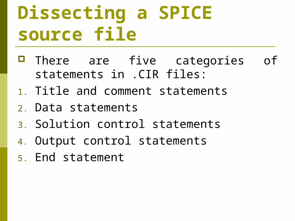
Dissecting a SPICE source file There are five categories of statements in
.CIR files:1. Title and comment statements2. Data statements3. Solution control statements4. Output control statements5. End statement
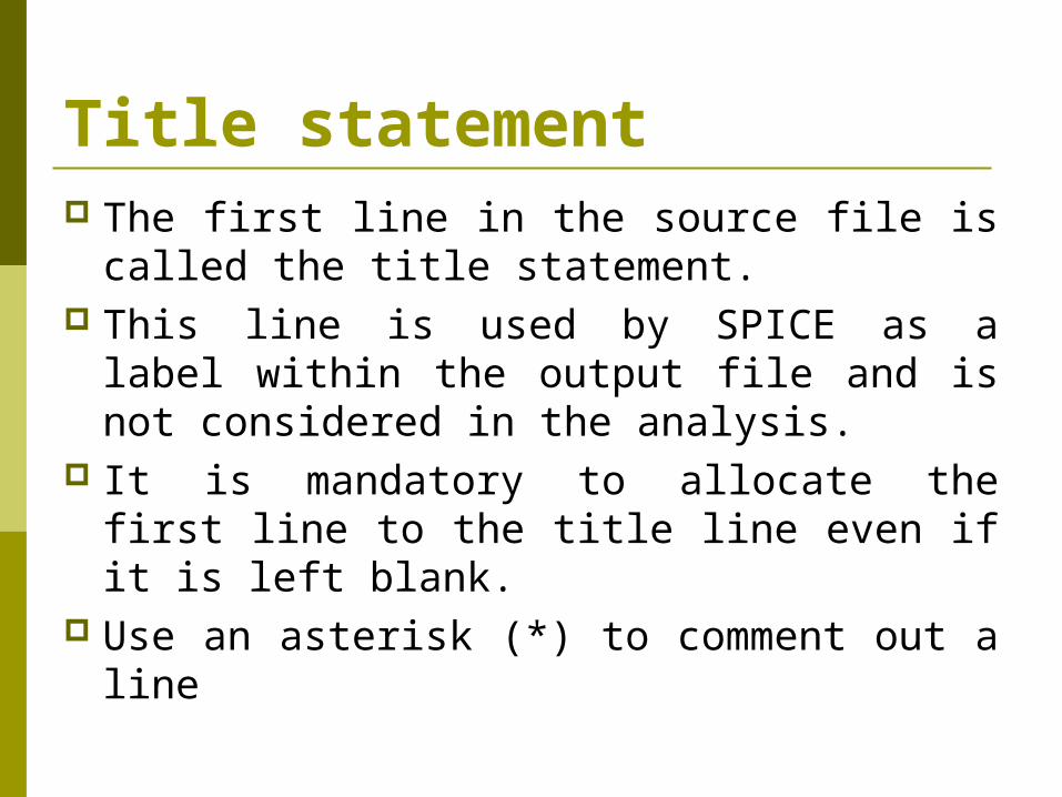
Title statement The first line in the source file is called the
title statement. This line is used by SPICE as a label within
the output file and is not considered in the analysis.
It is mandatory to allocate the first line to the title line even if it is left blank.
Use an asterisk (*) to comment out a line
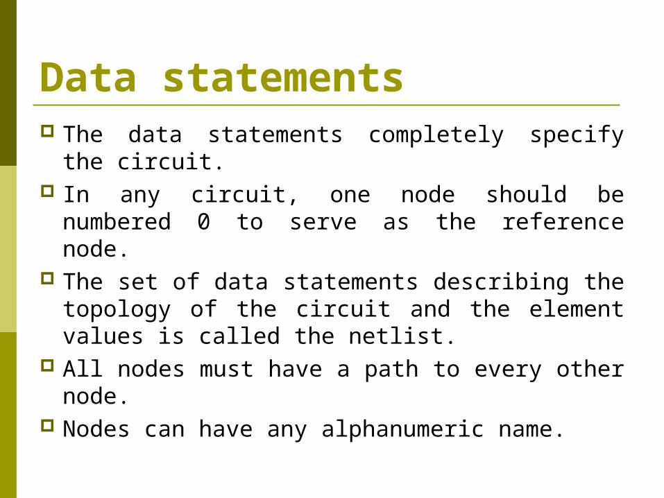
Data statements The data statements completely specify the
circuit. In any circuit, one node should be
numbered 0 to serve as the reference node. The set of data statements describing the
topology of the circuit and the element values is called the netlist.
All nodes must have a path to every other node.
Nodes can have any alphanumeric name.

Control and Output Statements In the absence of any additional
commands and only based on the netlist, SPICE automatically computes the DC values of the following quantities:
1. Node voltages with respect to node 0.2. Currents entering each voltage source
( from the + terminal).3. Total power dissipated in the circuit. Additional control and output statements
can be includes to specify other variables.

End Statement The .END statement is required at the end
of the source file. Any statement following this statement
will be considered as a separate source file.
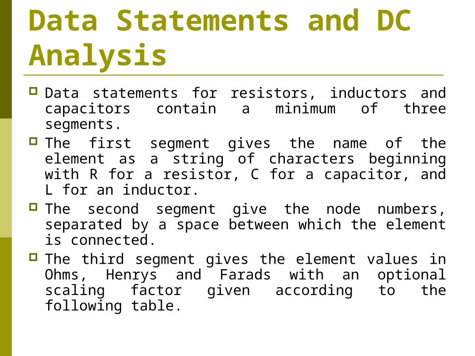
Data Statements and DC Analysis Data statements for resistors, inductors and
capacitors contain a minimum of three segments. The first segment gives the name of the element
as a string of characters beginning with R for a resistor, C for a capacitor, and L for an inductor.
The second segment give the node numbers, separated by a space between which the element is connected.
The third segment gives the element values in Ohms, Henrys and Farads with an optional scaling factor given according to the following table.

Data Statements and DC Analysis
Data Statements and DC Analysis Possible initial conditions can be given in
the optional fourth segment. A missing node is always taken to be the
reference node. To describe a short circuit use a very small
value. To describe an open circuit use a very
large value.

Data Statements and DC Analysis Independent sources are specified by four
segments. The first segment gives the name which for a
voltage source starts with V and for the current source starts with I.
The second segment contains the nodes, for voltage sources the first node indicates the positive terminal. The current in the current source flows from the first node to the second.
The third segment specifies the type of the source DC or AC.
The fourth segment contains the value.
Data Statements and DC Analysis For linearly dependent sources the name
should start with a letter as follows. Voltage–controlled voltage source E Current–controlled voltage source H Voltage–controlled current source G Current–controlled current source F The order of nodes is similar to the
dependent sources.
Data Statements and DC Analysis The third and fourth segments of the data
statement contain the control and the gain. For voltage-controlled sources the first node
in the control segment indicates the + terminal. The gain is the proportionality factor.
In the case of the current-controlled sources we first introduce a zero-valued voltage source on the path of the controlling current and use its name as the control variable.
Control and Output Statements in DC Analysis The output statement control the types
and number of calculated responses included in the output file
.OP statement has no parameters, it causes SPICE to calculate the dc operating point (OP) of all independent sources, it is the default command when no command statements are included in the input file.

Control and Output Statements in DC Analysis .DC statement sweeps the value of
an independent dc source. The syntax is:
.DC <source name> <initial value> <final value> <step size>
The .DC statement overrides the value in the input statement of the source.
Control and Output Statements in DC Analysis The .TF ( transfer function command) causes
SPICE to calculate three numbers: the circuit gain from input source to output variable, the input resistance as seen by the input source in ohms, the output resistance at the terminals defining the output variable in ohms.
The gain or transfer function is a number defined as:
gain=output variable / input source The unit for the gain depends on the units for the
output variable and the input source.
Control and Output Statements in DC Analysis The .PRINT statement in conjunction with
the .DC statement can be used to specify the calculated responses in the output file.
The syntax for the .Print statement is:.PRINT <analysis type> <output variable list> This statement restricts the calculated
responses in the output file to those given in the output variable list.
Control and Output Statements in DC Analysis When the analysis type is DC there must be
a .DC statement in the input file for the .PRINT statement to be executed.
The notation for the variable list is:1. V(N) is the node voltage at node N2. V(N1,N2) is the node voltage between nodes N1
and N2 with the plus sign at node N13. I(Vxxxx) is the current through the element
Vxxxx the reference direction for th current is determined by the first node listed in the input statement defining Vxxxx.
Control and Output Statements in DC Analysis The .PLOT statement line prints variables,
the syntax is:.PLOT <type> <output variables> .PROBE generates a data file *.DAT which
can be plotted in post analysis by evoking the Probe program. The syntax is:
.PROBE [<output variables>] If the .PROBE command is issued without
any parameters all variables will be saved

Control and Output Statements in DC Analysis To open the PROBE program, after you run
the .CIR file from PSpice A/D choose “Run Probe” from the “file” menu. When Probe opens choose “add” from the “trace” menu a list of variables appears, select the variable you want to see the plot for from


![TMS320x2833x, 2823x Enhanced Capture [ECAP] Module](https://img.pdfslide.net/doc/110x75/6281bc4b1f27011fbb2b4115/tms320x2833x-2823x-enhanced-capture-ecap-module-.jpg)