Embed Size (px)
Citation preview
Introduction to UMLLecture # 1
Department of Computer Science and TechnologyUniversity of Bedfordshire
Written by David Goodwin,
based on the book Applying UML and Patterns (3rd ed.)by C. Larman (2005).
Modelling and Simulation, 2012
Introduction toUML
CourseInformation
UML
StructureDiagrams
BehaviourDiagrams
InteractionDiagrams
Modelling
Use Case
summary
Outline
Course Information
UMLStructure DiagramsBehaviour DiagramsInteraction Diagrams
ModellingUse Case
summary
Introduction toUML
CourseInformation
UML
StructureDiagrams
BehaviourDiagrams
InteractionDiagrams
Modelling
Use Case
summary
Course Information
Introduction toUML
CourseInformation
UML
StructureDiagrams
BehaviourDiagrams
InteractionDiagrams
Modelling
Use Case
summary
Aims and Objectives
I To understand the software development process,including requirement specification, analysis, design,implementation and testing.
I To learn and use various methodologies in softwaredevelopment,
I To understand the process of modelling real worldproblems and systems using UML,
I To develop skills on object oriented softwaredevelopment (OOSD).
Introduction toUML
CourseInformation
UML
StructureDiagrams
BehaviourDiagrams
InteractionDiagrams
Modelling
Use Case
summary
Assesment
I Assignment:I One long, report style assignment, 50% (due 1630 27th
September 2012)
I Exam:I Final exam (Perception), 50% (2 hours, 1900-2100 27th
September 2012)
Introduction toUML
CourseInformation
UML
StructureDiagrams
BehaviourDiagrams
InteractionDiagrams
Modelling
Use Case
summary
Books
I Applying UML and patterns by Craig Larman
I Object-Oriented Software Engineering – a use casedriven approach (revised edition) by Ivar Jacobson
I UML Distilled (2nd Edition) by Martin Fowler
I Software Engineering (4th Edition) by Ian Sommerville
I Developing Applications with Java and UML by Paul Rand Reed Jr
I Practical Software Engineering by Leszek A Maciaszekand Bruc Lee Liong
Introduction toUML
CourseInformation
UML
StructureDiagrams
BehaviourDiagrams
InteractionDiagrams
Modelling
Use Case
summary
UML
Introduction toUML
CourseInformation
UML
StructureDiagrams
BehaviourDiagrams
InteractionDiagrams
Modelling
Use Case
summary
What is UML�
I UML stands for Unified Modelling Language.
I An industry standard modelling language forobject-oriented software engineering.
I Developed in the mid-1990’s and standardised in 1997(UML 1.1).
I UML 2.x is the current revision in use (we will focus onUML 2.0, revision from 2005).
I UML includes a set of graphic notation techniques tocreate visual models of object-orientedsoftware-intensive systems.
Introduction toUML
CourseInformation
UML
StructureDiagrams
BehaviourDiagrams
InteractionDiagrams
Modelling
Use Case
summary
List of object-oriented programminglanguages
I Languages designed mainly for object-orientedprogramming:
I C++I JavaI C#I Python
I Languages with some object-oriented features:I Visual BasicI FortranI PerlI PHP
Introduction toUML
CourseInformation
UML
StructureDiagrams
BehaviourDiagrams
InteractionDiagrams
Modelling
Use Case
summary
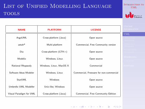
List of Unified Modelling Languagetools
NAME PLATFORM LICENSE
ArgoUML Cross-platform (Java) Open source
astah* Multi-platform Commercial, Free Community version
Dia Cross-platform (GTK+) Open source
Modelio Windows, Linux Open source
Rational Rhapsody Windows, Linux, MacOS X Commercial
Software Ideas Modeler Windows, Linux Commercial, Freeware for non-commercial
StarUML Windows Open source
Umbrello UML Modeller Unix-like; Windows Open source
Visual Paradigm for UML Cross-platform (Java) Commercial, Free Community Edition
Introduction toUML
CourseInformation
UML
StructureDiagrams
BehaviourDiagrams
InteractionDiagrams
Modelling
Use Case
summary
UML 2.0
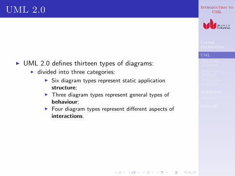
I UML 2.0 defines thirteen types of diagrams:I divided into three categories:
I Six diagram types represent static applicationstructure;
I Three diagram types represent general types ofbehaviour;
I Four diagram types represent different aspects ofinteractions.
Introduction toUML
CourseInformation
UML
StructureDiagrams
BehaviourDiagrams
InteractionDiagrams
Modelling
Use Case
summary
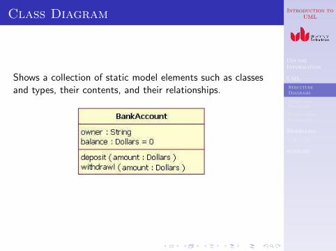
Class Diagram
Shows a collection of static model elements such as classesand types, their contents, and their relationships.
Introduction toUML
CourseInformation
UML
StructureDiagrams
BehaviourDiagrams
InteractionDiagrams
Modelling
Use Case
summary
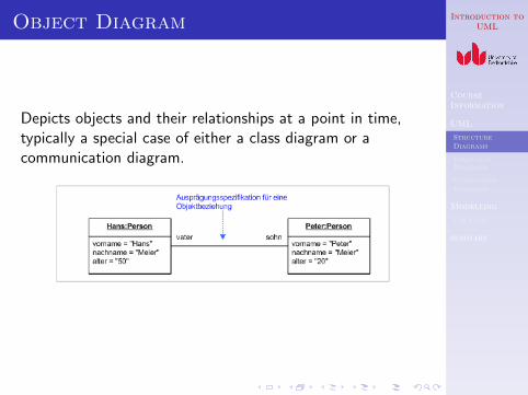
Object Diagram
Depicts objects and their relationships at a point in time,typically a special case of either a class diagram or acommunication diagram.
Introduction toUML
CourseInformation
UML
StructureDiagrams
BehaviourDiagrams
InteractionDiagrams
Modelling
Use Case
summary
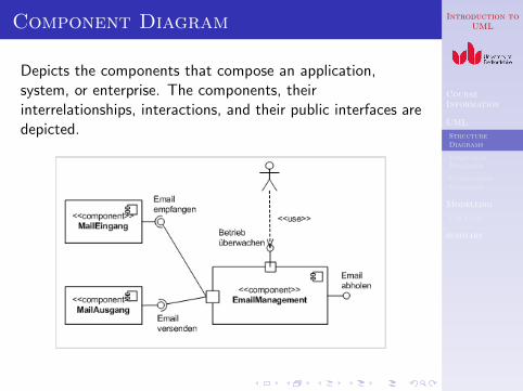
Component Diagram
Depicts the components that compose an application,system, or enterprise. The components, theirinterrelationships, interactions, and their public interfaces aredepicted.
Introduction toUML
CourseInformation
UML
StructureDiagrams
BehaviourDiagrams
InteractionDiagrams
Modelling
Use Case
summary
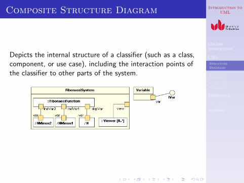
Composite Structure Diagram
Depicts the internal structure of a classifier (such as a class,component, or use case), including the interaction points ofthe classifier to other parts of the system.
Introduction toUML
CourseInformation
UML
StructureDiagrams
BehaviourDiagrams
InteractionDiagrams
Modelling
Use Case
summary
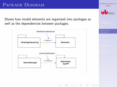
Package Diagram
Shows how model elements are organized into packages aswell as the dependencies between packages.

Introduction toUML
CourseInformation
UML
StructureDiagrams
BehaviourDiagrams
InteractionDiagrams
Modelling
Use Case
summary
Deployment Diagram
Shows the execution architecture of systems. This includesnodes, either hardware or software execution environments,as well as the middleware connecting them.
Introduction toUML
CourseInformation
UML
StructureDiagrams
BehaviourDiagrams
InteractionDiagrams
Modelling
Use Case
summary
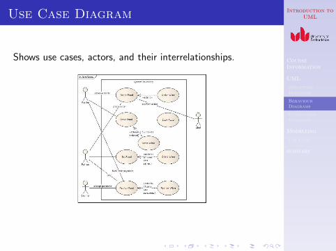
Use Case Diagram
Shows use cases, actors, and their interrelationships.
Introduction toUML
CourseInformation
UML
StructureDiagrams
BehaviourDiagrams
InteractionDiagrams
Modelling
Use Case
summary
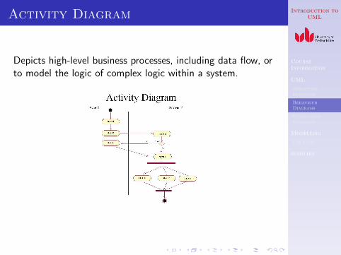
Activity Diagram
Depicts high-level business processes, including data flow, orto model the logic of complex logic within a system.
Introduction toUML
CourseInformation
UML
StructureDiagrams
BehaviourDiagrams
InteractionDiagrams
Modelling
Use Case
summary
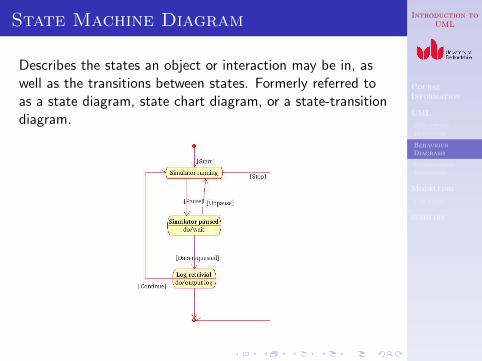
State Machine Diagram
Describes the states an object or interaction may be in, aswell as the transitions between states. Formerly referred toas a state diagram, state chart diagram, or a state-transitiondiagram.
Introduction toUML
CourseInformation
UML
StructureDiagrams
BehaviourDiagrams
InteractionDiagrams
Modelling
Use Case
summary
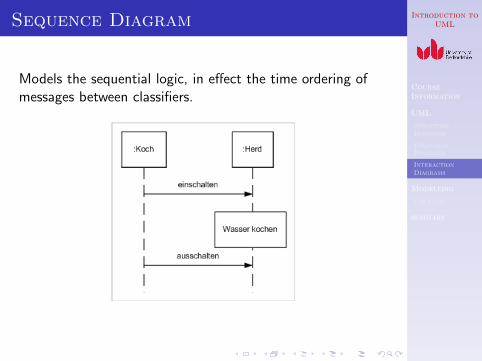
Sequence Diagram
Models the sequential logic, in effect the time ordering ofmessages between classifiers.
Introduction toUML
CourseInformation
UML
StructureDiagrams
BehaviourDiagrams
InteractionDiagrams
Modelling
Use Case
summary
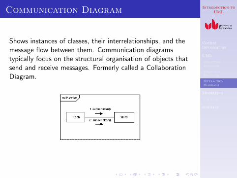
Communication Diagram
Shows instances of classes, their interrelationships, and themessage flow between them. Communication diagramstypically focus on the structural organisation of objects thatsend and receive messages. Formerly called a CollaborationDiagram.
Introduction toUML
CourseInformation
UML
StructureDiagrams
BehaviourDiagrams
InteractionDiagrams
Modelling
Use Case
summary
Timing Diagram
Depicts the change in state or condition of a classifierinstance or role over time. Typically used to show the changein state of an object over time in response to external events.
Introduction toUML
CourseInformation
UML
StructureDiagrams
BehaviourDiagrams
InteractionDiagrams
Modelling
Use Case
summary
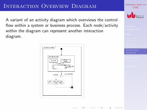
Interaction Overview Diagram
A variant of an activity diagram which overviews the controlflow within a system or business process. Each node/activitywithin the diagram can represent another interactiondiagram.
Introduction toUML
CourseInformation
UML
StructureDiagrams
BehaviourDiagrams
InteractionDiagrams
Modelling
Use Case
summary
Modelling
Introduction toUML
CourseInformation
UML
StructureDiagrams
BehaviourDiagrams
InteractionDiagrams
Modelling
Use Case
summary
System development
I System development is model buildingI Complexity of a large project
I A large number of componentsI A large amount of team work
I Linguistic communication between teams or betweenteam members is neither accurate nor reliable
I Models are standard representations and they areaccurate and reliable
I Modelling is the process of developing a modelI Various types of models for different purposes and
stages in software development
Introduction toUML
CourseInformation
UML
StructureDiagrams
BehaviourDiagrams
InteractionDiagrams
Modelling
Use Case
summary
Types of models
I Various types of modelsI Requirement model describes
I Users’ requirementsI Functionality
I Analysis model givesI System specificationsI A robust and changeable structure and structured
components
I Design model presentsI A refined structure to the current implementation
environment
I Implementation model documentsI Details of how a design is implemented
I Test model givesI VerificationI Validation
Introduction toUML
CourseInformation
UML
StructureDiagrams
BehaviourDiagrams
InteractionDiagrams
Modelling
Use Case
summary
Architecture
I Architecture of a modelling languageI Model architecture is a set of modelling language,
notation and modelling techniques.I A modelling language contains:
I Syntax - how it looksI Semantics - what it meansI Pragmatics - heuristics and rules of thumb for using it
I UMLI Unified Modelling Language is commonly acceptedI Idea first came from Ivar Jacocson in 1997
Introduction toUML
CourseInformation
UML
StructureDiagrams
BehaviourDiagrams
InteractionDiagrams
Modelling
Use Case
summary
Requirements Model
I Users’ requirements in software engineeringI A client/end-user’s needs and expectationsI Essential characteristics of the client/end-user’s goalI They are purely the user’s view of a systemI Requirements should be problem-based and not describe
solutions (Remember that no solution has yet beendeveloped)
I Requirements are often given in terms of what actuallyhappens within a physical, chemical, biochemical,business, transportation,. . . process.
I Requirements are modeled using Use Case diagrams
Introduction toUML
CourseInformation
UML
StructureDiagrams
BehaviourDiagrams
InteractionDiagrams
Modelling
Use Case
summary
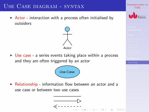
Use Case diagram - syntax
I Actor - interaction with a process often initialised byoutsiders
I Use case - a series events taking place within a processand they are often triggered by an actor
I Relationship - information flow between an actor and ause case or between two use cases
Introduction toUML
CourseInformation
UML
StructureDiagrams
BehaviourDiagrams
InteractionDiagrams
Modelling
Use Case
summary
Use Case diagram - pragmatics
I Identify actorsI What are entities outside of a process which trigger
information exchange with the process?I Can we classify them?
I Identify use casesI What are the main tasks of each actor?I How should the process response to each actor?I A use case should link to a scenario representing what
happens in the process in response to an actorI A use case should contain a complete course of events
related to the scenario
I Add relationshipI We need to pay extra attention on those between use
cases
Introduction toUML
CourseInformation
UML
StructureDiagrams
BehaviourDiagrams
InteractionDiagrams
Modelling
Use Case
summary
Use Case diagram - semantics
I An actor represents anything that is outside of a processbeing described and that needs to exchange informationwith the process
I An individual person (e.g. an end-user, an engineer)I A group of people who play the same role (e.g. cashers
in a bank)I An individual that can play different roles should be
represented as several actors according to his role in aprocess (e.g. HoD, researcher, lecturer)
I A machineI An objectI . . .
Introduction toUML
CourseInformation
UML
StructureDiagrams
BehaviourDiagrams
InteractionDiagrams
Modelling
Use Case
summary
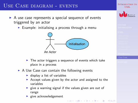
Use Case diagram - events
I A use case represents a special sequence of eventstriggered by an actor
I Example: initialising a process through a menu
I The actor triggers a sequence of events which takeplace in a process
I A Use Case can contain the following eventsI display a list of variablesI Accept values given by the actor and assigned to the
variablesI give a warning signal if the values given are out of
rangeI give acknowledgement
Introduction toUML
CourseInformation
UML
StructureDiagrams
BehaviourDiagrams
InteractionDiagrams
Modelling
Use Case
summary
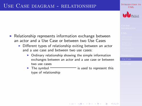
Use Case diagram - relationship
I Relationship represents information exchange betweenan actor and a Use Case or between two Use Cases
I Different types of relationship exiting between an actorand a use case and between two use cases:
I Ordinary relationship showing the simple informationexchanges between an actor and a use case or betweentwo use cases
I The symbol is used to represent thistype of relationship
Introduction toUML
CourseInformation
UML
StructureDiagrams
BehaviourDiagrams
InteractionDiagrams
Modelling
Use Case
summary
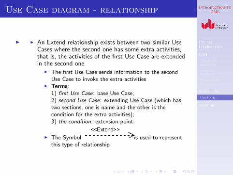
Use Case diagram - relationship
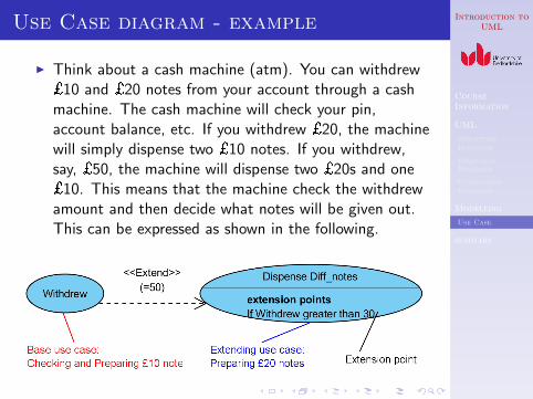
I I An Extend relationship exists between two similar UseCases where the second one has some extra activities,that is, the activities of the first Use Case are extendedin the second one
I The first Use Case sends information to the secondUse Case to invoke the extra activities
I Terms:1) first Use Case: base Use Case;2) second Use Case: extending Use Case (which hastwo sections, one is name and the other is thecondition for the extra activities);3) the condition: extension point.
I The Symbol is used to representthis type of relationship
Introduction toUML
CourseInformation
UML
StructureDiagrams
BehaviourDiagrams
InteractionDiagrams
Modelling
Use Case
summary
Use Case diagram - example
I Think about a cash machine (atm). You can withdrew£10 and £20 notes from your account through a cashmachine. The cash machine will check your pin,account balance, etc. If you withdrew £20, the machinewill simply dispense two £10 notes. If you withdrew,say, £50, the machine will dispense two £20s and one£10. This means that the machine check the withdrewamount and then decide what notes will be given out.This can be expressed as shown in the following.
Introduction toUML
CourseInformation
UML
StructureDiagrams
BehaviourDiagrams
InteractionDiagrams
Modelling
Use Case
summary
Use Case diagram - relationship
I I A Generalisation relationship also exists between twouse cases
I A group of use cases may have some common activitiesI A generalised use case contains those common
activities extracted from the group use casesI What left to the group of use cases are the specific
activities
I The Symbol is used to represent thistype of relationship
Introduction toUML
CourseInformation
UML
StructureDiagrams
BehaviourDiagrams
InteractionDiagrams
Modelling
Use Case
summary
Use Case diagram - example
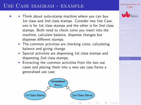
I I Think about auto-stamp machine where you can buy1st class and 2nd class stamps. Consider two Use Case,one is for 1st class stamps and the other is for 2nd classstamps. Both need to check coins you insert into themachine, calculate balance, dispense changes butdispense different stamps.
I The common activities are checking coins, calculatingbalance and giving change.
I Special activities are dispensing 1st class stamps anddispensing 2nd class stamps.
I Extracting the common activities from the two usecases and placing them into a new use case forms ageneralised use case
Introduction toUML
CourseInformation
UML
StructureDiagrams
BehaviourDiagrams
InteractionDiagrams
Modelling
Use Case
summary
summary
Introduction toUML
CourseInformation
UML
StructureDiagrams
BehaviourDiagrams
InteractionDiagrams
Modelling
Use Case
summary
Key Terms