Embed Size (px)
Citation preview
Structure1.1 Introduction
1.2 Definition of Buildings
1.3 Classification of Buildings as per NBC
1.4 Components parts of building
Learning objectivesAfter studying this unit, the student will be able to
• Under stand about building
• Classification of building
• Parts of building
1.1 IntroductionThe term building in civil engineering is used to mean a structure having
various components like foundations, walls, columns, roofs, doors, windows,ventilators lifts various types of surface finishes etc.
As a civil engineers is mainly concerned with the construction of building, it isessential for him to acquire good knowledge of construction of variouscomponents of building.
Introduction
1UNIT
Construction Technology2
1.2 Building A permanent fixed structure forming an enclosure and providing
protection from the elements.
A structure with a roof and walls is called a buildings.
Example: schools, houses, churches and factories are all buildings.
An area before or building the construction of a house is called building site.
1.3 Classifications Of Buildings As Per NBC(National Buildings Code)As per NBC Buildings are classified into Nine groups based on occupancy asfollows.
Group A : Residential Buildings.
Group B : Educational Buildings.
Group C : Institutional Buildings.
Group D : Assembly Buildings.
Group E : Business Buildings.
Group F : Mercantile Buildings.
Groups G : Industrial Buildings.
Groups H : Storage Buildings.
Group J : Hazardous Buildings.
Groups A :-Residential Buildings
These include any buildings in which sleeping accommodation is providedfor normal residential purpose with or without cooking or dining or both facilities.
Examples : Lodging or rooming houses, one or two family privatedwellings, Dorminatories, Apartment houses (Flats) Hotels, Inns, Clubs, andMotels.
Group B: Educational Buildings
These include any buildings used for school, college used for educational purpose.
Example : Schools and Colleges.
Paper - I Construction Practice 3
Group C : Institutional Buildings
These include buildings which are used for the purpose, such as medicalor other treatment or care of persons suffering from physical or mental illness, disease etc.
Example: Hospitals, Nursing homes, Jails, Prisons and Mental Hospital.
Group D : Assembly buildings
These include the buildings where groups of people assemble or gather for amusement, recreation, social, religious, patriotic, civil, travel and similarpurpose.
Example: Theaters, Auditions, Exhibition Halls, Clubrooms, Passenger Station, Recreation Places etc.
Group E : Business Buildings
These include the buildings which are used for transaction of business(other than covered by group) for keeping accounts and record and similarpurposes, services facilities etc.
Example : City Halls, Court Houses, Libraries etc.
Group F : Mercantile Buildings
These include the buildings which are uses as shops, stores, marketeither wholesaler or retail.
Group G : Industrial Buildings
These include the building in with products or materials of all kinds are fabricated, assembled and manufactured.
Example : Assembly plants, laboratories, power plants, smoke houses, refineries diaries and sew-mills.
Group H : Storage Buildings
These include the buildings for the storage of goods.
Example: ware houses, cold storage, store houses, truck and garages etc.
Group J : Hazardous Buildings
These include the building for storage, include manufacture for storage, handling, manufacture of explosive materials.
Construction Technology4
Example : (1) storage and handling of hazardous and highly inflammable liquids.
(2) manufacture of artificial flowers, explosives and fireworks.
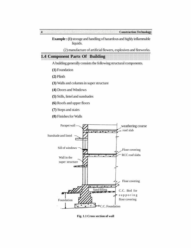
1.4 Component Parts Of BuildingA building generally consists the following structural components.
(1) Foundation
(2) Plinth
(3) Walls and columns in super structure
(4) Doors and Windows
(5) Stills, lintel and sunshades
(6) Roofs and upper floors
(7) Steps and stairs
(8) Finishes for Walls
Fig. 1.1 Cross section of wall
Parapet wall
Sunshade and lintel
Sill of windows
weathering courseroof slab
Floor covering
RCC roof slabs
Floor covering
C.C. Bed fors u p p o r i n gfloor covering
C.C. Foundation
Foundation
Wall in thesuper structure
Sand filling
Paper - I Construction Practice 5
Summary• A structure with a roof and walls is called a building.
• An Area before or during the construction of a house is called Building site.
• As per National Building Code (NBC) buildings are classified into Nine Groups i.e Group A,B,C,D,E,F,H, and J.
• A building generally consist of the following structural components such as foundation, walls and columns, Doors and Windows, Sills, Lintels and Sunshades, Roofs and Upper Floors and Finishes for walls.
Short Answer Type Questions1. Define Building.
2. Define Building site.
3. Mention the components parts of building.
Long Answer Type Questions1. Explain in details with examples, the classification of buildings as per
N.B.C.
2. State the different structural component of a building and indicate them an a neat sketch .
On Job Training
Visit different types of buildings and observes the component parts of building and maintain the record.
Construction Technology6
Structure2.1 Definition.
2.2 Functions of foundation.
2.3 Bearing capacity of soil.
2.4 Essential requirement of good foundation.
2.5 Classification of Foundation.
2.6 Construction details of spread footing.
2.7 Wall Footing, Raft Foundation
2.8 Cause and importance of insecticides, pesticides and their treatments
2.9 Cause of failure of foundation and remedial measures.
Learning objectivesAfter studying this unit the student should be able to understand.
• About foundations
• Bearing capacity of soil
• Shallows, rafts and spread foundation.
• Cause of failure of foundations and remedial measures.
• Requirement of goods foundation.
Foundation
2UNIT
Paper - I Construction Practice 7
2.1 Definition Foundation is the part of the building constructed below the ground level andwhich is in direct contact with sub-strata and transmits all the loads to the sub-soil.
2.2 Functions of foundationsThe foundation to be performed by the foundation are
1. To distribute the load coming on the structure over a large bearing area in order prevent any movement.
2. To distribute the load uniformly over the bearing surface so as to prevent unequal settlement.
3. To provide a level and firm natural bed for constructing the masonry over it.
4. To increase the stability of the structure.
5. To transit the loads of super structure to the soil safely.
2.3 Bearing capacity of soil The load of the structure is coming on the soil and hence it is importance toknow strength and behavior of the soil.
(1) Bearing capacity : The bearing capacity maybe defined as thelargest intensity of pressure which maybe applied by structure or a structuralmember to the soil which support it, without causing excessive settlement ordanger of failure of the soil in shear.
(2) Ultimate bearing capacity : ultimate bearing capacity is the migross pressure intensity at the base of the foundation at which the soil fail in shear.
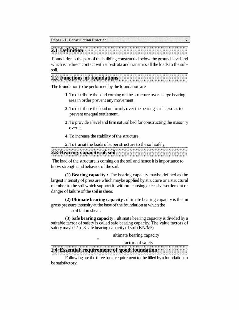
(3) Safe bearing capacity : ultimate bearing capacity is divided by asuitable factor of safety is called safe bearing capacity. The value factors ofsafety maybe 2 to 3 safe bearing capacity of soil (KN/M2).
ultimate bearing capacity factors of safety
2.4 Essential requirement of good foundationFollowing are the three basic requirement to the filled by a foundation to
be satisfactory.
=
Construction Technology8
1. Location : The foundation structure should be located that it is future influence which may adversely affect its performance
2. Stability : The foundation structure should be stable or safe against any possible failure.
3. Settlement : The foundation structure should not settle or defect to such an fullness or the stability of building or the a joining structure.
The above three requirements are independent of each other and forthe foundation structure to be satisfactory, all the three conditions should besatisfied.
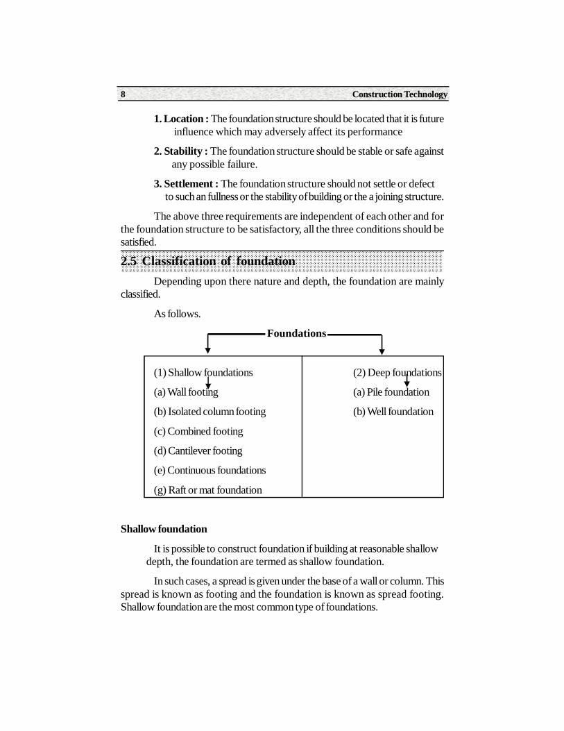
2.5 Classification of foundationDepending upon there nature and depth, the foundation are mainly
classified.
As follows.
Foundations
(1) Shallow foundations (2) Deep foundations
(a) Wall footing (a) Pile foundation
(b) Isolated column footing (b) Well foundation
(c) Combined footing
(d) Cantilever footing
(e) Continuous foundations
(g) Raft or mat foundation
Shallow foundation
It is possible to construct foundation if building at reasonable shallow depth, the foundation are termed as shallow foundation.
In such cases, a spread is given under the base of a wall or column. Thisspread is known as footing and the foundation is known as spread footing.Shallow foundation are the most common type of foundations.
Paper - I Construction Practice 9
Deep Foundation
When the foundations have to carry heavy structural loads through aweak compressible soils, the foundations are taken deeper depths until a hardstratum is reached such foundations are called as deep foundation.
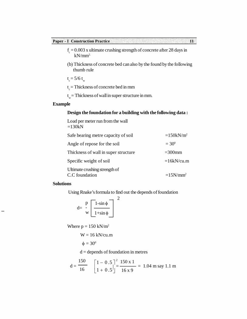
2.6 Construction details of spread footingDesign of spread foundation for a load bearing well consists of determining
the following elements
(1) Depth of foundation
(2) Width of foundation
(3) Thickness of concrete bed.
(1) Depth of foundation : Depth of foundation can be obtained bykeeping following rules in views.
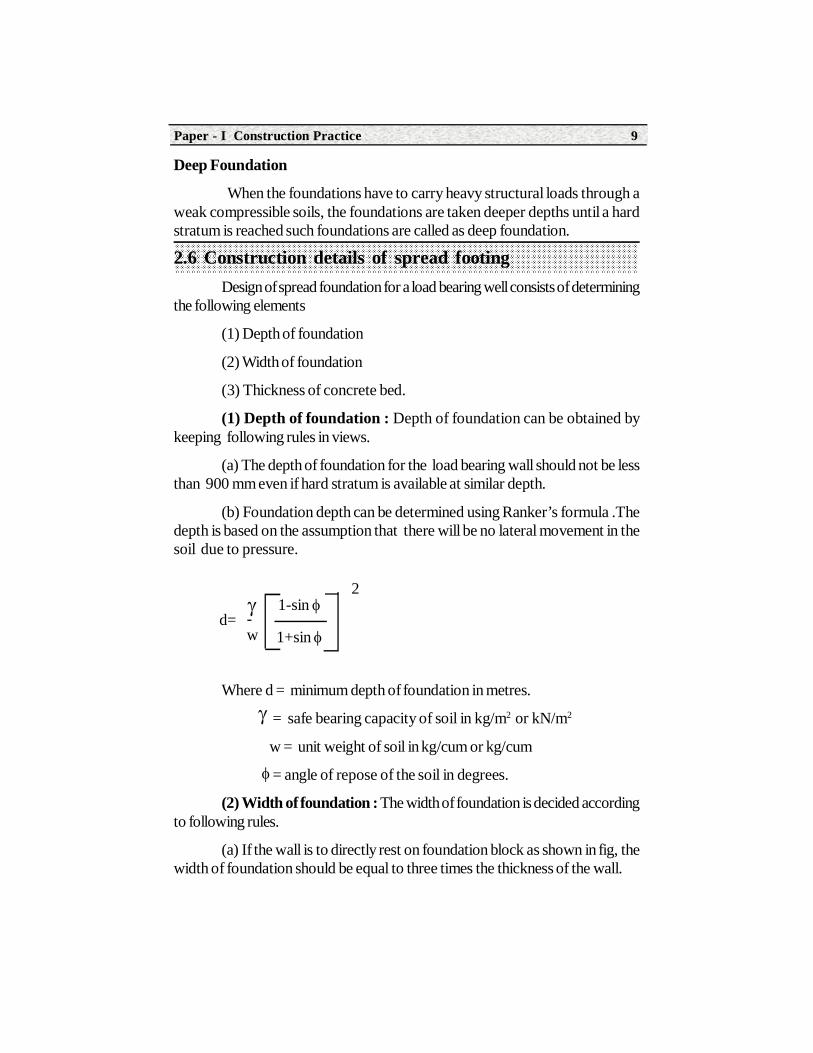
(a) The depth of foundation for the load bearing wall should not be lessthan 900 mm even if hard stratum is available at similar depth.
(b) Foundation depth can be determined using Ranker’s formula .Thedepth is based on the assumption that there will be no lateral movement in thesoil due to pressure.
Where d = minimum depth of foundation in metres.
= safe bearing capacity of soil in kg/m2 or kN/m2
w = unit weight of soil in kg/cum or kg/cum
= angle of repose of the soil in degrees.
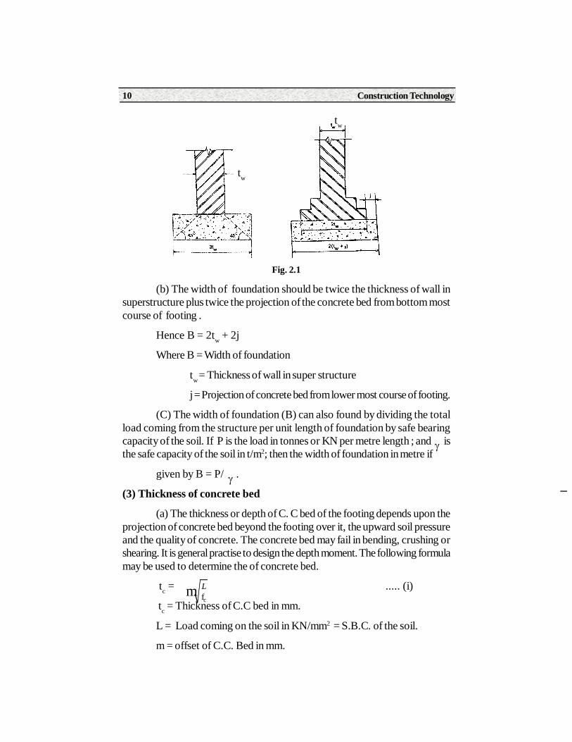
(2) Width of foundation : The width of foundation is decided accordingto following rules.
(a) If the wall is to directly rest on foundation block as shown in fig, thewidth of foundation should be equal to three times the thickness of the wall.
1-sin
1+sin
2
-w
d=
Construction Technology10
Fig. 2.1
(b) The width of foundation should be twice the thickness of wall insuperstructure plus twice the projection of the concrete bed from bottom mostcourse of footing .
Hence B = 2tw + 2j
Where B = Width of foundation
tw = Thickness of wall in super structure
j = Projection of concrete bed from lower most course of footing.
(C) The width of foundation (B) can also found by dividing the totalload coming from the structure per unit length of foundation by safe bearingcapacity of the soil. If P is the load in tonnes or KN per metre length ; and isthe safe capacity of the soil in t/m2; then the width of foundation in metre if
given by B = P/ .
(3) Thickness of concrete bed
(a) The thickness or depth of C. C bed of the footing depends upon theprojection of concrete bed beyond the footing over it, the upward soil pressureand the quality of concrete. The concrete bed may fail in bending, crushing orshearing. It is general practise to design the depth moment. The following formulamay be used to determine the of concrete bed.
tc = ..... (i)
tc = Thickness of C.C bed in mm.
L = Load coming on the soil in KN/mm2 = S.B.C. of the soil.
m = offset of C.C. Bed in mm.
tw
tw
cfm L
Paper - I Construction Practice 11
fc = 0.003 x ultimate crushing strength of concrete after 28 days in kN/mm2.
(b) Thickness of concrete bed can also by the found by the following thumb rule
tc = 5/6 tw
tc = Thickness of concrete bed in mm
tw = Thickness of wall in super structure in mm.
Example
Design the foundation for a building with the following data :
Load per meter run from the wall =130kN
Safe bearing metre capacity of soil =150kN/m2
Angle of repose for the soil = 300
Thickness of wall in super structure =300mm
Specific weight of soil =16kN/cu.m
Ultimate crushing strength ofC.C foundation =15N/mm2
Solutions
Using Rnake’s formula to find out the depends of foundation
Where p = 150 kN/m2
W = 16 kN/cu.m
= 300
d = depends of foundation in metres
1-sin
1+sin
2p-w
d=
21 0 .51 0 .5
150 x 1
16 x 9
150
16d = = = 1.04 m say 1.1 m
Construction Technology12
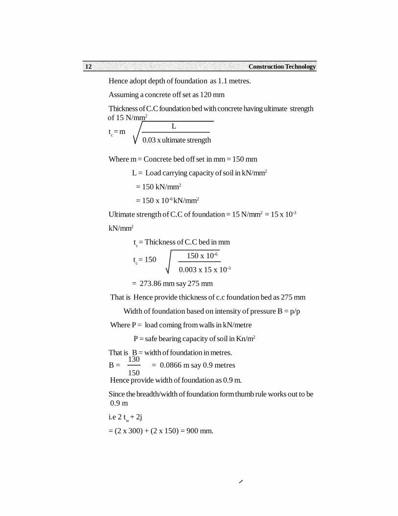
Hence adopt depth of foundation as 1.1 metres.
Assuming a concrete off set as 120 mm
Thickness of C.C foundation bed with concrete having ultimate strength of 15 N/mm2
tc = m
Where m = Concrete bed off set in mm = 150 mm
L = Load carrying capacity of soil in kN/mm2
= 150 kN/mm2
= 150 x 10-6 kN/mm2
Ultimate strength of C.C of foundation = 15 N/mm2 = 15 x 10-3
kN/mm2
tc = Thickness of C.C bed in mm
150 x 10-6
0.003 x 15 x 10-3
= 273.86 mm say 275 mm
That is Hence provide thickness of c.c foundation bed as 275 mm
Width of foundation based on intensity of pressure B = p/p
Where P = load coming from walls in kN/metre
P = safe bearing capacity of soil in Kn/m2
That is B = width of foundation in metres.
Hence provide width of foundation as 0.9 m.
Since the breadth/width of foundation form thumb rule works out to be 0.9 m
i.e 2 tw + 2j
= (2 x 300) + (2 x 150) = 900 mm.
L
0.03 x ultimate strength
tc = 150
B = = 0.0866 m say 0.9 metres130
150
Paper - I Construction Practice 13
i.e provide Depth of foundation = 1.1m width of foundation = 0.9m;thickness of c.c bed = 0.275m.
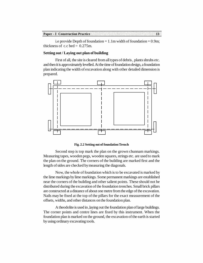
Setting out / Laying out plan of building
First of all, the site is cleared from all types of debris , plants shrubs etc.and then it is approximately levelled. At the time of foundation design, a foundationplan indicating the width of excavation along with other detailed dimension isprepared.
Fig. 2.2 Setting out of foundation Trench
Second step is top mark the plan on the grown chunnam markings.Measuring tapes, wooden pegs, wooden squares, strings etc. are used to markthe plan on the ground. The corners of the building are marked first and thelength of sides are checked by measuring the diagonals.
Now, the whole of foundation which is to be excavated is marked bythe lime markings by lime markings. Some permanent markings are establishednear the corners of the building and other salient points. These should not bedistributed during the excavation of the foundation trenches. Small brick pillarsare constructed at a distance of about one metre from the edge of the excavation.Nails may be fixed at the top of the pillars for the exact measurement of theoffsets, widths, and other distances on the foundation plan.
A theodolite is used in ,laying out the foundation plan of large buildings.The corner points and centre lines are fixed by this instrument. When thefoundation plan is marked on the ground, the excavation of the earth is startedby using ordinary excavating tools.
Construction Technology14
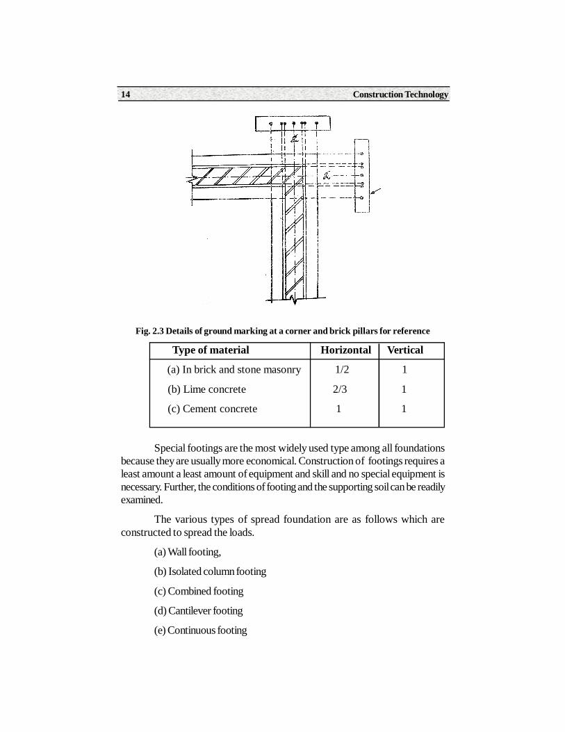
Fig. 2.3 Details of ground marking at a corner and brick pillars for reference
Type of material Horizontal Vertical
(a) In brick and stone masonry 1/2 1
(b) Lime concrete 2/3 1
(c) Cement concrete 1 1
Special footings are the most widely used type among all foundationsbecause they are usually more economical. Construction of footings requires aleast amount a least amount of equipment and skill and no special equipment isnecessary. Further, the conditions of footing and the supporting soil can be readilyexamined.
The various types of spread foundation are as follows which areconstructed to spread the loads.
(a) Wall footing,
(b) Isolated column footing
(c) Combined footing
(d) Cantilever footing
(e) Continuous footing
Paper - I Construction Practice 15
(f) Grillage foundation
(g) Raft or mat foundation.
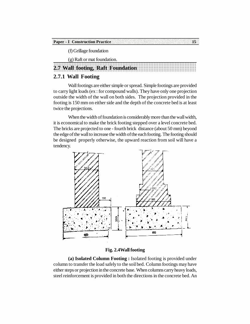
2.7 Wall footing, Raft Foundation2.7.1 Wall Footing
Wall footings are either simple or spread. Simple footings are providedto carry light loads (ex : for compound walls). They have only one projectionoutside the width of the wall on both sides. The projection provided in thefooting is 150 mm on either side and the depth of the concrete bed is at leasttwice the projections.
When the width of foundation is considerably more than the wall width,it is economical to make the brick footing stepped over a level concrete bed.The bricks are projected to one - fourth brick distance (about 50 mm) beyondthe edge of the wall to increase the width of the each footing. The footing shouldbe designed properly otherwise, the upward reaction from soil will have atendency.
Fig. 2.4Wall footing
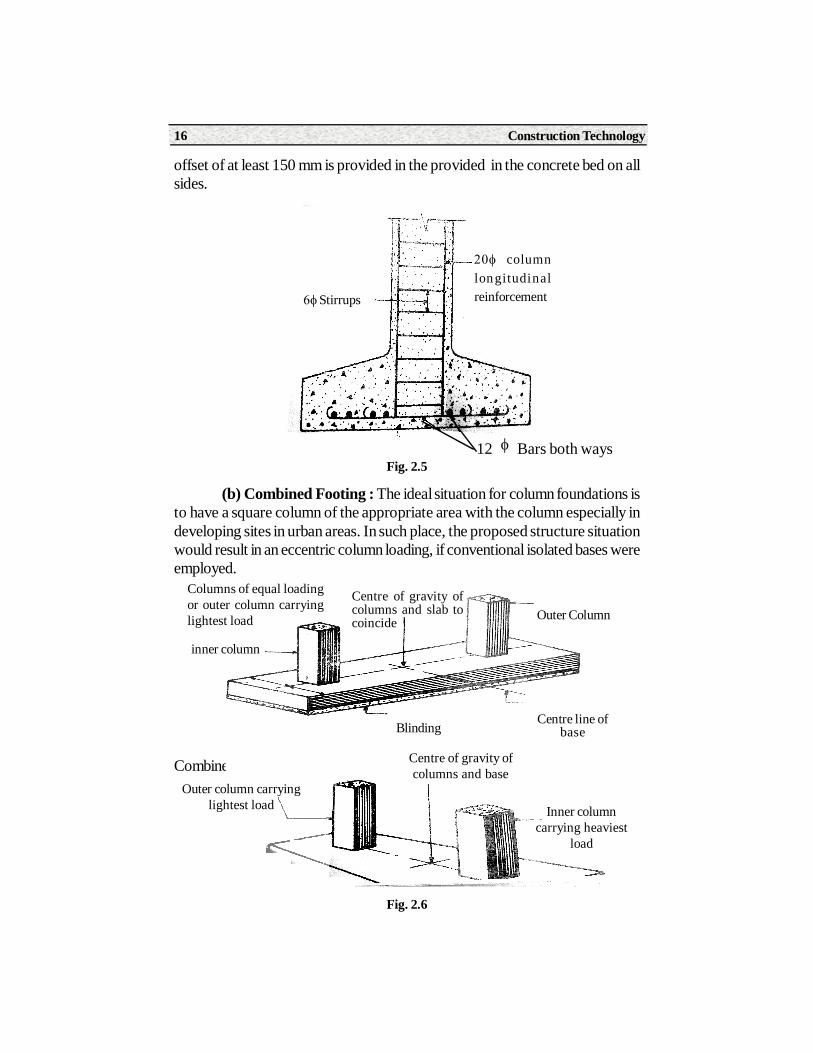
(a) Isolated Column Footing : Isolated footing is provided undercolumn to transfer the load safely to the soil bed. Column footings may haveeither steps or projection in the concrete base. When columns carry heavy loads,steel reinforcement is provided in both the directions in the concrete bed. An
Construction Technology16
offset of at least 150 mm is provided in the provided in the concrete bed on allsides.
Fig. 2.5
(b) Combined Footing : The ideal situation for column foundations isto have a square column of the appropriate area with the column especially indeveloping sites in urban areas. In such place, the proposed structure situationwould result in an eccentric column loading, if conventional isolated bases wereemployed.
Combined column foundation
Columns of equal loadingor outer column carryinglightest load
Centre of gravity ofcolumns and slab tocoincide Outer Column
Centre line ofbaseBlinding
inner column
Outer column carryinglightest load
Centre of gravity ofcolumns and base
Inner columncarrying heaviest
load
Fig. 2.6
Stirrups
columnlongitudinalreinforcement
12 Bars both ways
Paper - I Construction Practice 17
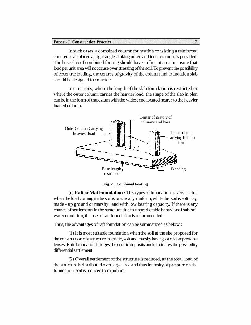
In such cases, a combined column foundation consisting a reinforcedconcrete slab placed at right angles linking outer and inner columns is provided.The base slab of combined footing should have sufficient area to ensure thatload per unit area will not cause over stressing of the soil. To prevent the possibilityof eccentric loading, the centres of gravity of the column and foundation slabshould be designed to coincide.
In situations, where the length of the slab foundation is restricted orwhere the outer column carries the heavier load, the shape of the slab in plancan be in the form of trapezium with the widest end located nearer to the heavierloaded column.
Fig. 2.7 Combined Footing
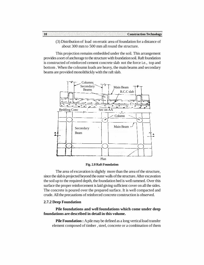
(c) Raft or Mat Foundation : This types of foundation is very usefullwhen the load coming in the soil is practically uniform, while the soil is soft clay,made - up ground or marshy land with low bearing capacity. If there is anychance of settlements in the structure due to unpredictable behavior of sub-soilwater condition, the use of raft foundation is recommended.
Thus, the advantages of raft foundation can be summarized as below :
(1) It is most suitable foundation when the soil at the site proposed forthe construction of a structure in erratic, soft and marshy having lot of compressiblelenses. Raft foundation bridges the erratic deposits and eliminates the possibilitydifferential settlement.
(2) Overall settlement of the structure is reduced, as the total load ofthe structure is distributed over large area and thus intensity of pressure on thefoundation soil is reduced to minimum.
Outer Column Carryingheaviest load
Center of gravity ofcolumns and base
Inner columncarrying lightest
load
Base lengthrestricted
Blending
Construction Technology18
(3) Distribution of load on erratic area of foundation for a distance of about 300 mm to 500 mm all round the structure.
This projection remains embedded under the soil. This arrangementprovides a sort of anchorage to the structure with foundation soil. Raft foundationis constructed of reinforced cement concrete slab not the force i.e., top andbottom . When the coloumn loads are heavy, the main beams and secondarybeams are provided monolithickly with the raft slab.
Fig. 2.8 Raft Foundation
The area of excavation is slightly more than the area of the structure,since the slab is projected beyond the outer walls of the structure. After excavationthe soil up to the required depth, the foundation bed is well rammed. Over thissurface the proper reinforcement is laid giving sufficient cover on all the sides.The concrete is poured over the prepared surface. It is well compacted andcrude. All the precautions of reinforced concrete construction is observed.
2.7.2 Deep Foundation
Pile foundations and well foundations which come under deepfoundations are described in detail in this volume.
Pile Foundation : A pile may be defined as a long vertical load transfer element composed of timber , steel, concrete or a combination of them
ColumnsSecondary
BeamsMain Beam
R.C.C slab
Bedding Conc Sec on AA
Column
Main BeamSecondaryBeam
Plan
Paper - I Construction Practice 19
The main function of pile os to carry load of the structure which cannotbe sufficiently supported at a certain level due to its poor bearing capacity to adepth at which good bearing capacity is available.
Types of Piles : In general, there are two types of piles.
(1) Bearing Piles : When a pile passes through poor material nut its tip(bottom end) penetrates a small length in to a stratum of good bearing capacity,then it is called a bearing pile.
The hard stratum or bed rock must be at a reasonable depth and thereshould be no too soft stratum below the hard stratum. Bearing piles transfertheir load to the hard stratum.
Friction piles : When a piles passes through deep strata of limitedbearing capacity and develope their carrying capacity by friction on the sides ofthe pile ( circumference of the pile), then they are called fiction piles. The frictionpile derives its support mainly from the surrounding soil through the developmentof friction between the soil and the periphery of pile.
A very small percentage of the load is carried by the soil near the lowertip of the pile . Friction piles are used when hard stratum of bed rock is at a largedepth . The length of friction pile depends upon the type of soil, amount of loadand the size of pile.
Other Piles : Besides these two main types of piles, there are a numbertip of the pile. Friction piles are used for specific purposes . They are compactionpiles, Anchor piles, Dolphin and Batter piles.
Compaction piles are used to compact loose granular soils there byincreasing the bearing capacity. When friction piles are driven in coarse grainedsoil, the process of driving such piles close to each other in group greatly reducesthe porosity and compressibility of the soil within and around. Thus they compactthe soil.
Compaction piles do not carry any load themselves.
Tension piles anchor down the structure which are subjected to or dueto over turning movement.
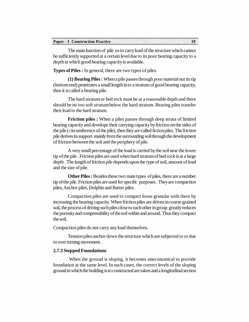
2.7.3 Stepped Foundations
When the ground is sloping, it becomes uneconomical to providefoundation at the same level. In such cases, the correct levels of the slopingground in which the building is to constructed are taken and a longitudinal section
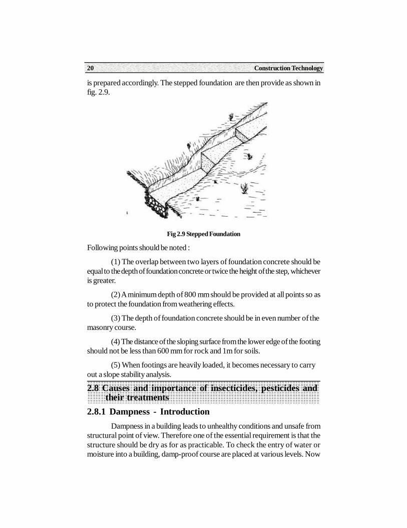
Construction Technology20
is prepared accordingly. The stepped foundation are then provide as shown infig. 2.9.
Fig 2.9 Stepped Foundation
Following points should be noted :
(1) The overlap between two layers of foundation concrete should beequal to the depth of foundation concrete or twice the height of the step, whicheveris greater.
(2) A minimum depth of 800 mm should be provided at all points so asto protect the foundation from weathering effects.
(3) The depth of foundation concrete should be in even number of themasonry course.
(4) The distance of the sloping surface from the lower edge of the footingshould not be less than 600 mm for rock and 1m for soils.
(5) When footings are heavily loaded, it becomes necessary to carryout a slope stability analysis.
2.8 Causes and importance of insecticides, pesticides and their treatments2.8.1 Dampness - Introduction
Dampness in a building leads to unhealthy conditions and unsafe fromstructural point of view. Therefore one of the essential requirement is that thestructure should be dry as for as practicable. To check the entry of water ormoisture into a building, damp-proof course are placed at various levels. Now
Paper - I Construction Practice 21
a-days, all the buildings are provided with damp-proof of course to preventdampness from affecting a building or the person living in the buildings.
Cause of Dampness
Absorption of water by poor quality materials, is the chief source ofdampness. Granular materials absorb water easily and this and this water mayfind access, to the inside of building in one way or other. Following may be thepossible causes responsible for entry of dampness into a structure.
(1) Orientation of the building : The walls getting more frequent splashof water, and less sunshine during the hotter part of the day are effected bydampness. Due to certain geographical conditions of the , orientation of thebuildings also plays an important role in damp prevention.
(2) Rain Water : The rain water can directly penetrate from roof or itsvarious components such as gutter, dormer windows etc. The dampness canalso enter into the walls from its exposed faces which are subjected to heavyshowers of rain and are properly protected against dampness.
(3) Exposed tops of wall : Dampness- proof course should be providedat the top of boundry walls and parapet walls to check the entry of water throughthe top of walls, otherwise the dampness may cause serious damage.
(4) Rise of Ground Moisture : Moisture form wet ground may risewell above ground level due to capillary in flows is caused due to this reason.
(5) Condensation : Cool air can contain lesser amount of water vapourthan warm air. Hence the moisture is depicted on the walls, roofs, etc., whenwarm humid air is cooled. This process is known as condensation.
(6) Poor drainage of the site : In low lying areas, water cannot beeasily drained off and creates water logging in impervious soil is encounteredbeneath the building. The dampness will prevail in the structures located in suchareas.
(7) Bad Workmanship : Defective construction of the joints in theroofs, throat in of soil and copings, fixture in the buildings etc., causes dampnessby allowing entry of the water inside the building. If proper slope entry of thewater inside the buildings. If proper slope is not provided in the roof, rain watergets accumulated on the roof, and thus causing dampness.
2.8.2 Effects of Dampness
The main effects are as follows :
(1) It create unhealthy condition for the occupants of the building.
Construction Technology22
(2) It causes efflorescence which may finally result in the disintegration of bricks, tiles etc.
(3) Plaster become soft and crumbled.
(4) It cause warping and decay of timber.
(5) The metals used in the construction of the building are subjected to corrosion.
(6) It causes blistering , bleaching and flaking of paints.
(7) Electrical insulation are damaged.
(8) The floors covering materials are deteriorated.
(9) Termite grows faster and dampness becomes the source for mosquito breeding.
Method of Termite-Proofing :
The methods of termite mentioned below are applicablew to thesubterrances termits only which cause serious damage to the buildings. Thedrywood termites can be effectively controlled by using preservatives-treatedtimber. The methods of termit proofing can drywood termites can be effectivelycontrolled by using preservatives-treated timber. The methods of termit proofingcan broadly be classified into the following two groups :
(i) Soil treatment with chemicals
(ii) Structural
(10) Soil treatment with chemical The soils insecticied atre thoroughlymixed and well spread in soil so as to provide an effective barrier for termite.The various patented chemicals insecticides such as DDT, BHC, PCP, etc . areavailable but the following chemicals in oil solution or preferably water emulsionhave proved to be successful.
(1) Aldrin........................... 0.5 per cent
(2) Chlordane.................... 1.0 per cent
(3) Dieldrin ....................... 0.5 per cent
(4) Heptachlor................... 0.5 per cent
The above concentrations are by weight. All chemicals are chlorinatedhydrocarbons. They are insoluble in water and hence they are not leached outby the subsoil water. The application of these chemicals serve as a chemical
Paper - I Construction Practice 23
barrier between the building and the ground and this method has proved to bethe most effecting method of termit-proofing.
The soil treatments with chemical should start when the foundationtrenches are ready to take mass concrete in foundation. The laying of massconcrete should start when the chemical emulsion has been absorbed by the soiland the surface is dry. The treatment should not be carried should not be outwhen it is raining or when the soil is wet with rain or subsoil water.
The chemical solution be uniformly spread and for this purpose, a suitablehand operated compressed air sprayer or vessel containing water should beused.
All the soil insecticides are poisonous. There will be adverse effects ifthese chemicals are absorbed through skin, in held as vapor or swallwood. It istherefore necessary to follow strictly the precaution mentioned on the containersof insecticides.
(2) Structural barriers : To prevent the entry of termites through walls,the impenetrable physical structural barriers may be provided continuously atPlinth level. Such structural barrier may be in the form of a cement concretelayer or metal layer at Plinth level. The cement concrete layer or coping is 50mmto 75 mm thick and it is preferable to keep it projecting about 50 mm to 75 mminternally and externally. The metal barriers consist of sheets of non-corrodiblemetals such as copper or galvanized iron, having a thickness of about of about0.80 mm. The metal barrier are likely to be damages and may then prove to beinefficient against termits.
2.9 Causes of failure of foundation and preventive measuresThe main cause of failure of foundation are as follows :
(1) Unequal settlement of the sub-soil
(2) Unequal settlement of the masonry
(3) Withdrawal of moisture from the sub-soil
(4) Lateral pressure on the superstructure
(5) Horizontal movement of the earth
(6) Transpiration of trees and shrubs
(7) Atmosphere action.
Construction Technology24
We will now discuss each one in details together with the measures tobe taken prevent such failures.
(1) Unequal Settlement of the sub-soil : This occurs due to variousreasons such as unequal distribution of load on the foundation, varying bearingpower of the sun-soil, eccentricity of the load, etc. Due to unequal settlement ofthe sub-soil, the crakes are formed in the buildings, which in future, leads toserious defects
Following are the measures to be adopted to prevent such failure :
(i) The foundation should rest on the rock or hard morim
(ii) The design of foundation should be appropriate to the nature of sub-soil.
(iii) It should be seen that the allowable bearing pressure on the soil is not exceeded, even under the worst conditions.
(iv) The proper attention should be given to the eccenticity of the loads on the foundations and design should be accordingly modified.
(2) Unequal settlement of the masonry : The mortars used as thebuilding material in the masonry construction shrink sand gets compresses whenloaded excessively before it has fully set. This may lead to the unequal settlementof the masonry and the measures to avoid such situation are as follows :
(i) The mortar to be used in the masonry should be stiff in line with the workable desired.
(ii) The masonry work should be raised evenly.
(iii) The height of wall to be raised day should be limited to one metre, if lime mortar is used and to 1.50 metres, if cement mortar is used.
(iv) The proper watering or curing for a period at least 10 days shouldbe done to the masonry works to ensure the development of adequate strengthof the mortar joints.
(3) Withdrawal of moistures from the sub-soil : This occurs at placeswhere there is considerably variation in the height of water table. When watertable falls, the soils particles loose cohesion and hence, there is shrinkage ofsoils, resulting in the crackes to the buildings. The precautions to be taken toavoid such failure would be to drive piles upto the hard rock.
(4) Lateral pressure on the superstructure : The thrust of a pitchedroof or arch action on the superstructure causes wall to overturn. The remedial
Paper - I Construction Practice 25
measures to prevent this failure would be to provide a sufficient wide base andto design the foundation for the worst conditions.
(5) Horizontal movement of the earth : Very soft soil is liable to giveway under the action in load, especially at place such as sloping ground, riverbanks, etc. Hence, in such cause, it is desirable construct the retaining walls orto drive sheet piles to prevent the escape of the earth.
(6) Transpiration of trees and shrubs : the roots of trees plantednear a building a may absorb the moisture. This effects is seen in the form of adepression on the ground and it may lead to cracks in the building. The remedialmeasures are as follow :
(i) The foundation should be taken sufficiently deep. A minimum depth of one metre is required for this purpose.
(ii) The fast growing and water trees should not be planed near thebuilding with a minimum distance of 8 metres.
(7) Atmosphere action : The rain and sun are main atmosphere agentsto seriously affect the foundation of a building. The heavy rains or considerablevariation in temperature or frost action may damage the foundations. The rainwater may create pockets near the walls and while descending, it may carrychemical and salts obtained from sewage, animal dung etc. These chemical andsalts may react with the material used for the foundation work and turn them intopowder. The remedial measures to be taken are as follow :
(i) The foundation should be taken beyond the depth upto which rain can reach.
(ii) Suitable underground drains should be provided to maintain the water table at a definite level.
(iii) After the masonry work is completed, the sides of trenches shouldbe carefully filled with earth and well - consolidated. A gentle slope should beprovided so as to keep rain water from the wall.
Summary• Foundation is the lowest part of super structure, which transfer the load of super strucutre to the sub soil.
• Super structure is used to mean that part of the structure which is above ground level.
• A part of superstructure located between the ground level and the floor level is known as Plinth.
Construction Technology26
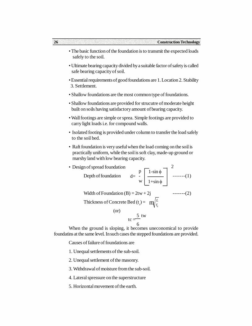
• The basic function of the foundation is to transmit the expected loads safely to the soil.
• Ultimate bearing capacity divided by a suitable factor of safety is called safe bearing capacity of soil.
• Essential requirements of good foundations are 1. Location 2. Stability 3. Settlement.
• Shallow foundations are the most common type of foundations.
• Shallow foundations are provided for strucutre of moderate height built on soils having satisfactory amount of bearing capacity.
• Wall footings are simple or sprea. Simple footings are provided to carry light loads i.e. for compound walls.
• Isolated footing is provided under column to transfer the load safely to the soil bed.
• Raft foundation is very useful when the load coming on the soil is practically uniform, while the soil is soft clay, made-up ground or marshy land with low bearing capacity.
• Design of spread foundation
Depth of foundation -------(1)
Width of Foundation (B) = 2tw + 2j -------(2)
Thickness of Concrete Bed (tc) =
(or)
tc =
When the ground is sloping, it becomes uneconomical to providefoundatins at the same level. In such cases the stepped foundations are provided.
Causes of failure of foundations are
1. Unequal settlements of the sub-soil.
2. Unequal settlement of the masonry.
3. Withdrawal of moisture from the sub-soil.
4. Lateral spressure on the superstructure
5. Horizontal movement of the earth.
1-sin
1+sin
2p-w
d=
cfm L
5 tw
6
Paper - I Construction Practice 27
6. Transmission of trees and shrubs.
7. Atmospheric action.
The following three important treatment to be given to the buildings tocontrol damp water leakage and termites 1. Damp-proofing 2. Water proofing3. Termite proofing.
Short Answer Type Questions1. Define the term “Foundation”
2. Define the terms
a. Ultimate bearing capacity of the soil.
b. Safe bearing capacity of the soil.
3. Write the functions to be performed by a foundation of a building.
4. List the type sof foundations that are included in shallow foundations.
5. Draw a neat sketch of wall footing.
6. Draw a neat sketch of Isolated column footing.
7. List the types of foundation that are included in “Deep-foundation”.
8. Define Damp-proof course.
Long Answer Type Questions1. Explain the requirements of good foundation
2. Draw a neat sketch of Raft foundation and explain.
3. Explain effect of dampness in a building.
4. What are the causes of dampness in a building.
5. Explain the method of termite proofing.
6. Explain the design of spread foundation.
7. Explain stepped foundation.
8. Explain the causes of failure of foundations and preventive measures.
On Job Training1. Visit different types of strucutures which are under construction.
2. Observe and record the data of different types of foundation.
Construction Technology28
Structure3.0 Introduction
3.1 Stone Masonry
3.2 Brick Masonry
Learning ObjectivesAfter completing this unit the student shall be able to understand
The definition of stone masonry, materials required for stone masonry,Classification of stone masonry, Rubble Masonry and Ashlar Masonry. Toolsrequired for masonry, Types of joints in stone masonry, Supervising points instone masonry. Definition of brick masonry, Types of brick masonry, Englishbond and Flamish Bond, Defects in brick masonry, structures in Brick masonry,tools required, points to be remembered in supervisioning in brick masonry.
3.0 IntroductionMen learnt to utilize stones for their needs since the beginning of the
civilization. Thus stone is used for construction from the beginning of humansettlement. Stone masonry is used for the construction of foundations, walls forsimple structures to various Architectural master pieces like Taj Mahal andwonders of the world like Pyramids. The stone masonry in this chapter covers
3UNIT
Masonry
29Paper - I Construction Practice
the various types of stone masonry and the points to be remembered whilesupervising its construction.
3.1 Stone Masonry3.1.1 Definition
Stone masonry is the art of systematic arrangement of stones, bondingthem together with mortar, to form a homogenous mass.3.1.2 Materials required for stone masonry
The materials required for stone masonry are stone and mortar.Stone : Depending upon the availability and architectural appearance
required, stones are selected. The stones used for the work should be hard,durable, tough and free from any defects.
Mortar : The mortar is required to keep the stones in position. It isprepared by mixing cement or lime with sand. Water is added to this mixture toform mortar. This mortar is placed in the joints of the masonry. Depending onthe strength required and resistance to weathering, the proportions of the mortarare decided.
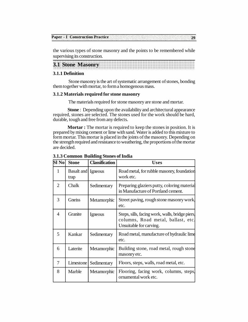
3.1.3 Common Building Stones of IndiaSl No
1
2
3
4
5
6
7
8
Stone
Basalt andtrap
Chalk
Gneiss
Granite
Kankar
Laterite
Limestone
Marble
Classification
Igneous
Sedimentary
Metamorphic
Igneous
Sedimentary
Metamorphic
Sedimentary
Metamorphic
Uses
Road metal, for rubble masonry, foundationwork etc.
Preparing glaziers putty, coloring materialin Manufacture of Portland cement.
Street paving, rough stone masonry work,etc.
Steps, sills, facing work, walls, bridge piers,columns, Road metal, ballast, etc.Unsuitable for carving.
Road metal, manufacture of hydraulic limeetc.
Building stone, road metal, rough stonemasonry etc.
Floors, steps, walls, road metal, etc.
Flooring, facing work, columns, steps,ornamental work etc.
Construction Technology30
3.1.4 Some Definitions in stone masonry
Natural bed : The plane along which the stone can be split easily is thenatural bed of stone. In stone masonry the natural bed should be perpendicularto the direction of the pressure.
Sill : The bottom surface of a door or window opening is known as sill.
Course : A layer of stones or bricks is known as a course.
Coping : To protect the wall from rain water, a course of stone is provided at the top of the wall. Such a course of stone is known as coping.
Plinth : The height of ground floor level above ground level is known asplinth.
Spalls : The chips of stones used to fill the empty faces in stone masonryare known as spalls. These are used in dry masonry.
Quoins : The external corners or angles of a wall surface are known asthe quoins.
Jambs : The sides of the opening such as doors, windows are knownas jambs.
Face : The surface of a wall exposed to weather is known as facing. Itis the external side of the wall.
Back : The inner surface of the wall which is not exposed to weather isknown as back.
3.1.5 Classification of Stone Masonry
Stone masonry is broadly classified as Rubble masonry and Ashlarmasonry.
Rubble masonry is further classified as
• Coursed rubble masonry
• Un coursed rubble masonry
9
10
11
Quartzite
Sandstone
Slate
Metamorphic
Sedimentary
Metamorphic
Retaining walls, road metal, rubble masonry,aggregate etc.
Steps, facing work, columns, flooring, walls,road metal Ornamental craving,etc.
Roofing work, sills, damp-proof courses,etc.
31Paper - I Construction Practice
• Random rubble masonry
• Dry rubble masonry
• Polygonal masonry
• Flint masonry
• Ashlar masonry is further classified as
• Ashlar fine
• Ashlar rough tooled
• Ashlar rock or quarry faced
• Ashlar chamfered
• Ashlar block in course.
3.1.6 Rubble and Ashlar masonry
Rubble masonry : In rubble masonry, the stones of irregular sizes areused. Rubble masonry is further classified as Coursed rubble masonry and uncoursed rubble masonry depending on the size of the stones used.
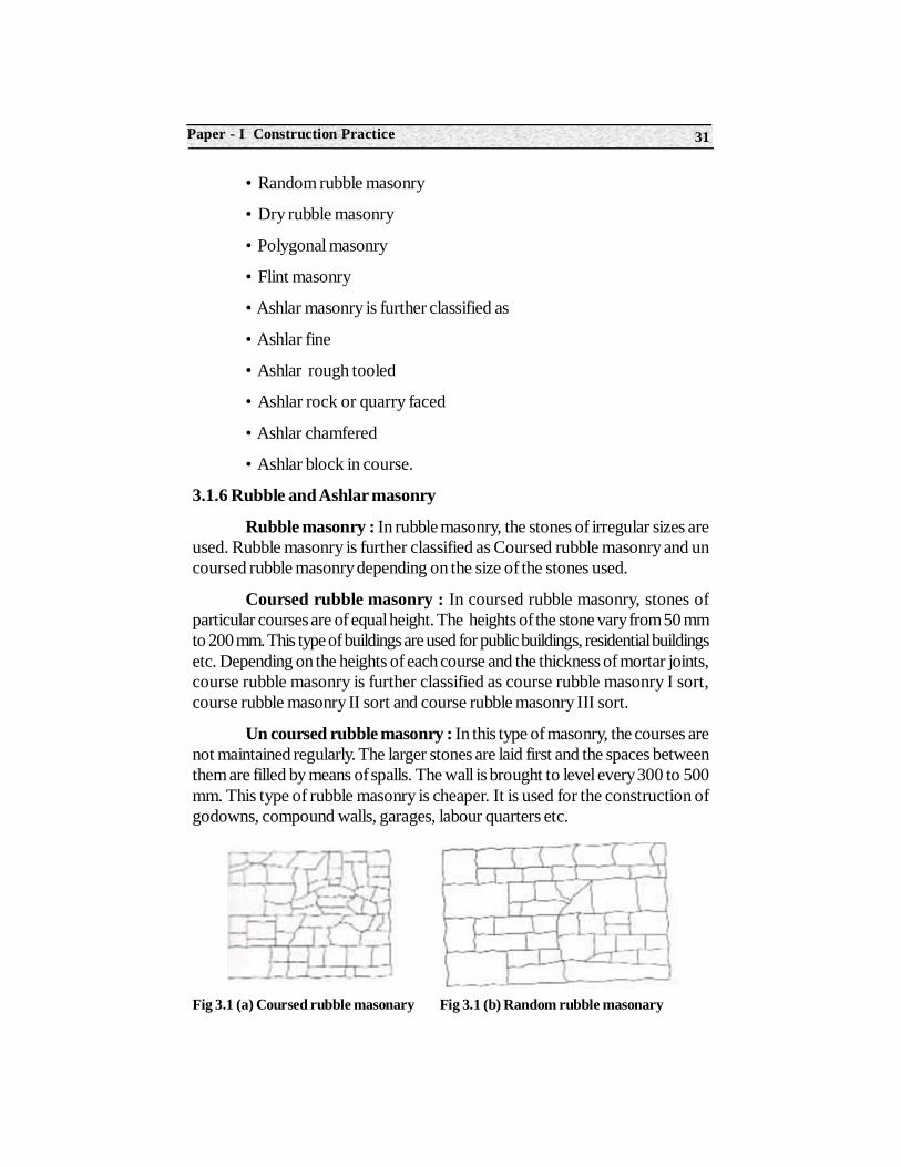
Coursed rubble masonry : In coursed rubble masonry, stones ofparticular courses are of equal height. The heights of the stone vary from 50 mmto 200 mm. This type of buildings are used for public buildings, residential buildingsetc. Depending on the heights of each course and the thickness of mortar joints,course rubble masonry is further classified as course rubble masonry I sort,course rubble masonry II sort and course rubble masonry III sort.
Un coursed rubble masonry : In this type of masonry, the courses arenot maintained regularly. The larger stones are laid first and the spaces betweenthem are filled by means of spalls. The wall is brought to level every 300 to 500mm. This type of rubble masonry is cheaper. It is used for the construction ofgodowns, compound walls, garages, labour quarters etc.
Fig 3.1 (a) Coursed rubble masonary Fig 3.1 (b) Random rubble masonary
Construction Technology32
Random rubble masonry : In this type of masonry, the stones areselected at random. Their size and shape is not considered. Skill is required tomake this masonry structurally stable. This type of masonry is used forconstruction of foundations, compound walls, godowns etc.
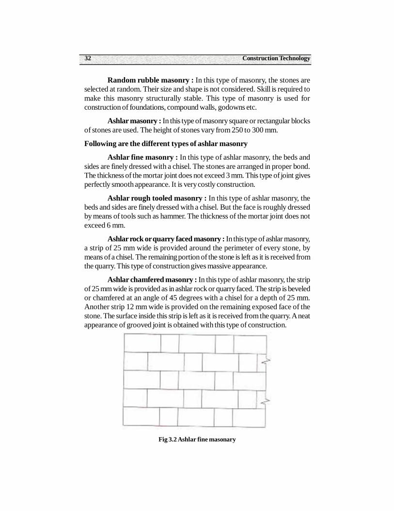
Ashlar masonry : In this type of masonry square or rectangular blocksof stones are used. The height of stones vary from 250 to 300 mm.
Following are the different types of ashlar masonry
Ashlar fine masonry : In this type of ashlar masonry, the beds andsides are finely dressed with a chisel. The stones are arranged in proper bond.The thickness of the mortar joint does not exceed 3 mm. This type of joint givesperfectly smooth appearance. It is very costly construction.
Ashlar rough tooled masonry : In this type of ashlar masonry, thebeds and sides are finely dressed with a chisel. But the face is roughly dressedby means of tools such as hammer. The thickness of the mortar joint does notexceed 6 mm.
Ashlar rock or quarry faced masonry : In this type of ashlar masonry,a strip of 25 mm wide is provided around the perimeter of every stone, bymeans of a chisel. The remaining portion of the stone is left as it is received fromthe quarry. This type of construction gives massive appearance.
Ashlar chamfered masonry : In this type of ashlar masonry, the stripof 25 mm wide is provided as in ashlar rock or quarry faced. The strip is beveledor chamfered at an angle of 45 degrees with a chisel for a depth of 25 mm.Another strip 12 mm wide is provided on the remaining exposed face of thestone. The surface inside this strip is left as it is received from the quarry. A neatappearance of grooved joint is obtained with this type of construction.
Fig 3.2 Ashlar fine masonary
33Paper - I Construction Practice
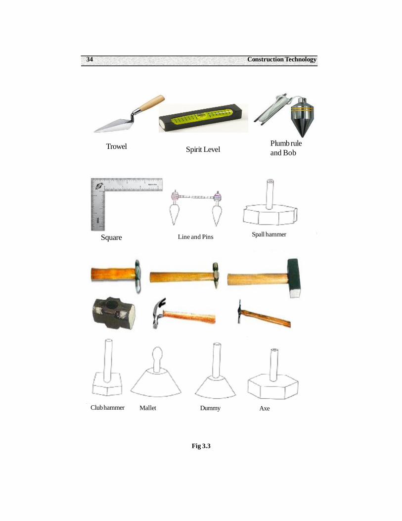
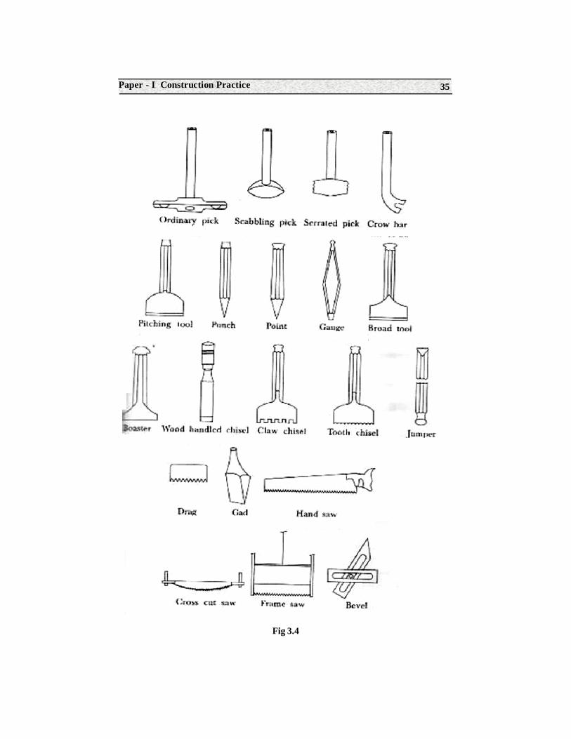
3.1.7 Table : Tools For Stone Masonry
3.1.8 Joints in stone masonary
1. Butt or square joint : In this type of joint, the square surface of onestone is placed against that of another. This is the most common joint. It isextensively used for ordinary work.
2. Rebated or lapped joint : In this type of joint, the rebates areprovided to prevent the movement of stones. This type of joint is used for archwork, coping on gables, etc.
3. Tongued and grooved joint : In this type of joint, a projection iskept on one stone and a corresponding sinking is provided on the other stone.This type of joints is provided for the ends of ashlar masonry.
4. Tabled joint : In this type of joint, a projection is formed on the bedof one stone and sinking is provided at the stone above it. The depth of projectionis about 40 mm and the width of projection is about one third of the width of thestone. This type of joint is used where the lateral pressure is heavy.
5. Rusticated joint : Sometimes the margins or edges of stones usedfor plinth, quoin, etc are sunk below the general level. Such types of joint areknown as rusticated joint.
Sl.No.
1.
2.
3.
4.
5.
6.
7.
8.
9.
10.
Name of the tool
Trowel
Spirit level
Plumb rule and bob
Square
Line and pins
Spall hammer
Mash hammer and Wallerhammer
Axe
Pitching tool
Jumper
Uses
To lift and to spread mortar
To check the horizontality of the work
To check the verticality of the work
To set right angles
To maintain the alignment
To dress the stones in the quarry
To dress the stones
To dress roughly and to split the stonesin the quarry
To make the stones of required size
To bore holes for blasting purposes ina quarry
Construction Technology34
Fig 3.3
Trowel Spirit LevelPlumb ruleand Bob
Square Spall hammer
Club hammer
Line and Pins
Mallet Dummy Axe
35Paper - I Construction Practice
Fig 3.4
Construction Technology36
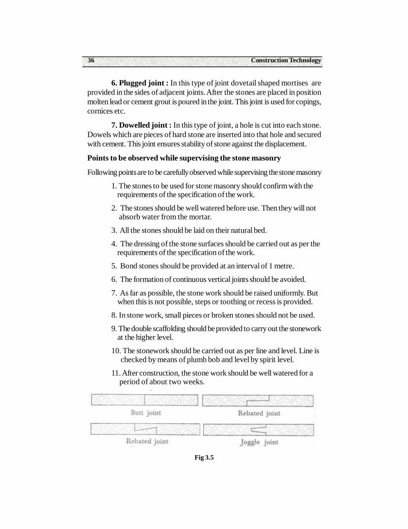
6. Plugged joint : In this type of joint dovetail shaped mortises areprovided in the sides of adjacent joints. After the stones are placed in positionmolten lead or cement grout is poured in the joint. This joint is used for copings,cornices etc.
7. Dowelled joint : In this type of joint, a hole is cut into each stone.Dowels which are pieces of hard stone are inserted into that hole and securedwith cement. This joint ensures stability of stone against the displacement.
Points to be observed while supervising the stone masonry
Following points are to be carefully observed while supervising the stone masonry
1. The stones to be used for stone masonry should confirm with the requirements of the specification of the work.
2. The stones should be well watered before use. Then they will not absorb water from the mortar.
3. All the stones should be laid on their natural bed.
4. The dressing of the stone surfaces should be carried out as per the requirements of the specification of the work.
5. Bond stones should be provided at an interval of 1 metre.
6. The formation of continuous vertical joints should be avoided.
7. As far as possible, the stone work should be raised uniformly. But when this is not possible, steps or toothing or recess is provided.
8. In stone work, small pieces or broken stones should not be used.
9. The double scaffolding should be provided to carry out the stonework at the higher level.
10. The stonework should be carried out as per line and level. Line is checked by means of plumb bob and level by spirit level.
11. After construction, the stone work should be well watered for a period of about two weeks.
Fig 3.5
37Paper - I Construction Practice
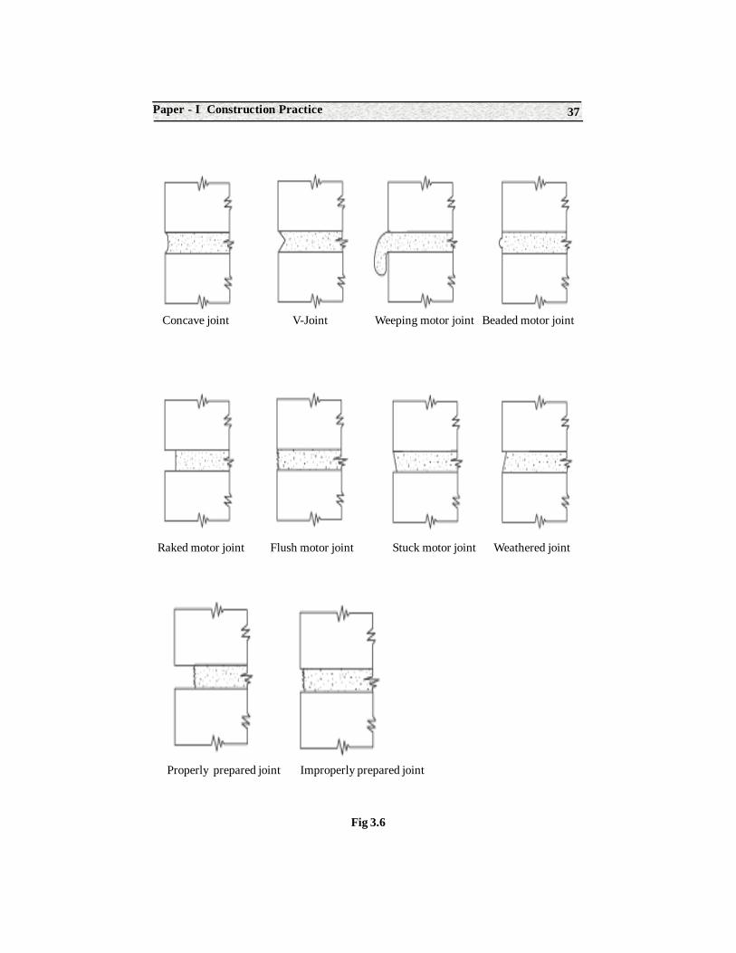
Fig 3.6
Concave joint V-Joint Weeping motor joint Beaded motor joint
Raked motor joint Flush motor joint Stuck motor joint Weathered joint
Properly prepared joint Improperly prepared joint
Construction Technology38
3.2 Brick MasonryIntroduction
Bricks are rectangular blocks of uniform size. They can be properlyarranged and bonded together. Further lifting devices are not required as theyare light in weight. Hence brick masonry is extensively used in the constructionof walls, arches, water supply and sanitation etc.
3.2.1. Definition of brick masonry
The systematic arrangement of bricks and binding them together withmortar to form a homogeneous mass is known as brick masonry.
Some definitions
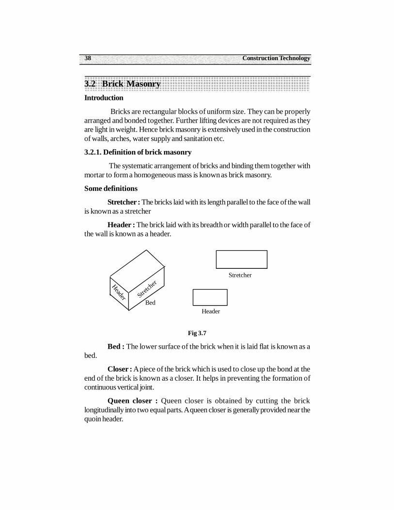
Stretcher : The bricks laid with its length parallel to the face of the wallis known as a stretcher
Header : The brick laid with its breadth or width parallel to the face ofthe wall is known as a header.
Fig 3.7
Bed : The lower surface of the brick when it is laid flat is known as abed.
Closer : A piece of the brick which is used to close up the bond at theend of the brick is known as a closer. It helps in preventing the formation ofcontinuous vertical joint.
Queen closer : Queen closer is obtained by cutting the bricklongitudinally into two equal parts. A queen closer is generally provided near thequoin header.
Stretch
erHeader
Bed
Stretcher
Header
39Paper - I Construction Practice
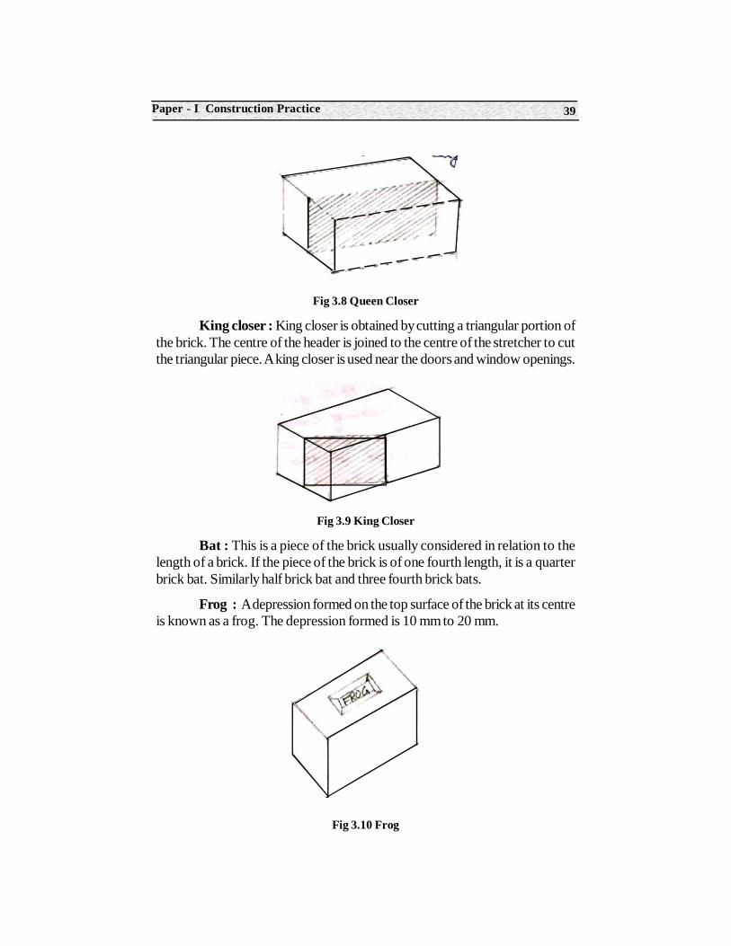
Fig 3.8 Queen Closer
King closer : King closer is obtained by cutting a triangular portion ofthe brick. The centre of the header is joined to the centre of the stretcher to cutthe triangular piece. A king closer is used near the doors and window openings.
Fig 3.9 King Closer
Bat : This is a piece of the brick usually considered in relation to thelength of a brick. If the piece of the brick is of one fourth length, it is a quarterbrick bat. Similarly half brick bat and three fourth brick bats.
Frog : A depression formed on the top surface of the brick at its centreis known as a frog. The depression formed is 10 mm to 20 mm.
Fig 3.10 Frog
Construction Technology40
3.2.2 Types of brick masonry
The brick masonry is classified into various types, according to the typeof mortar, quality of bricks and thickness of mortar joints.
1. Brick work in mud : In this type of brick work, the mud is used tofill up the joints. The mud is prepared by intimately mixing sand with clay. Thethickness of the mortar joint is 12 mm. This type of brick work is adopted in thecase of cheap construction. The maximum height of the wall should not exceed4.0 m.
2. Brick work in cement mortar or lime mortar First class : In thistype of brick work, cement or lime mortar is used. The bricks are table moulded,and they are of standard shape and size, and they are burnt in kilns. The surfaceand the edges of the brick are sharp, square and straight. The thickness of thejoint does not exceed 10 mm.
3. Brick work in cement mortar or lime mortar second class :The bricks to be used in this type of brick work are moulded on ground andthey are burnt in kilns. The surface of the brick is some what rough and theshape is slightly irregular. The edges of the bricks are not sharp and uniform.The thickness of the mortar joint is 12 mm. These bricks are commonly usedwhen they will be covered with plastering.
4. Brick work in cement mortar or lime mortar third class : Thebricks used are ground moulded and they are burnt in clamps. The bricks arenot hard and they have rough surfaces with irregular and distorted edges. Thistype of brick work is used for unimportant and temporary works.
3.2.3 Various types of bonds in brick work
The following are the various types of bonds in brick work.
1. Stretcher bond
2. Header bond
3. English bond
4. Flemish bond
5. Garden wall bond
6. Raking bond
7. Dutch bond
8. Bricks on edge bond
41Paper - I Construction Practice
Out of all these types of bonds, the load bearing walls are constructedin English bond and Flemish bond only. The stretcher bond consists of bricksarranged in stretcher courses while the header bond consists of bricks arrangedin header courses. The English bond is considered as the strongest. The Flemishbond gives better appearance. The garden wall bond is confined to gardenwalls, compound walls, etc. The raking bond consists of bricks placed in inclineddirection. The Dutch bond is the modified form of English bond. Here the quoinof the stretcher is a three fourth brick bat. IN bricks on edge bond, the bricksare laid on its edge instead of bricks on bed as in other types of bonds.
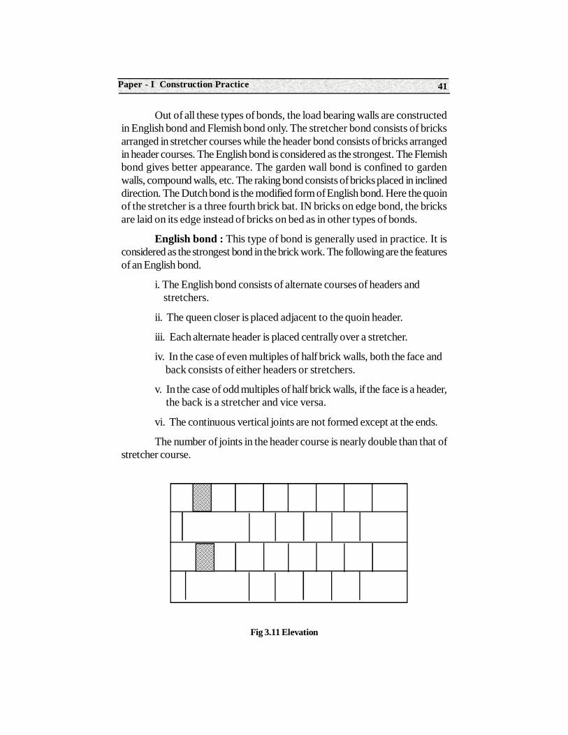
English bond : This type of bond is generally used in practice. It isconsidered as the strongest bond in the brick work. The following are the featuresof an English bond.
i. The English bond consists of alternate courses of headers and stretchers.
ii. The queen closer is placed adjacent to the quoin header.
iii. Each alternate header is placed centrally over a stretcher.
iv. In the case of even multiples of half brick walls, both the face and back consists of either headers or stretchers.
v. In the case of odd multiples of half brick walls, if the face is a header, the back is a stretcher and vice versa.
vi. The continuous vertical joints are not formed except at the ends.
The number of joints in the header course is nearly double than that ofstretcher course.
Fig 3.11 Elevation
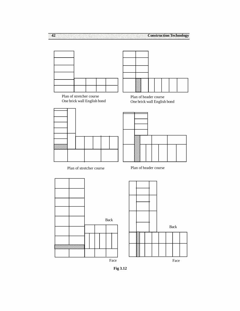
Construction Technology42
Fig 3.12
Plan of stretcher courseOne brick wall English bond
Plan of header courseOne brick wall English bond
Plan of stretcher course Plan of header course
Back
Face
Back
Face
43Paper - I Construction Practice
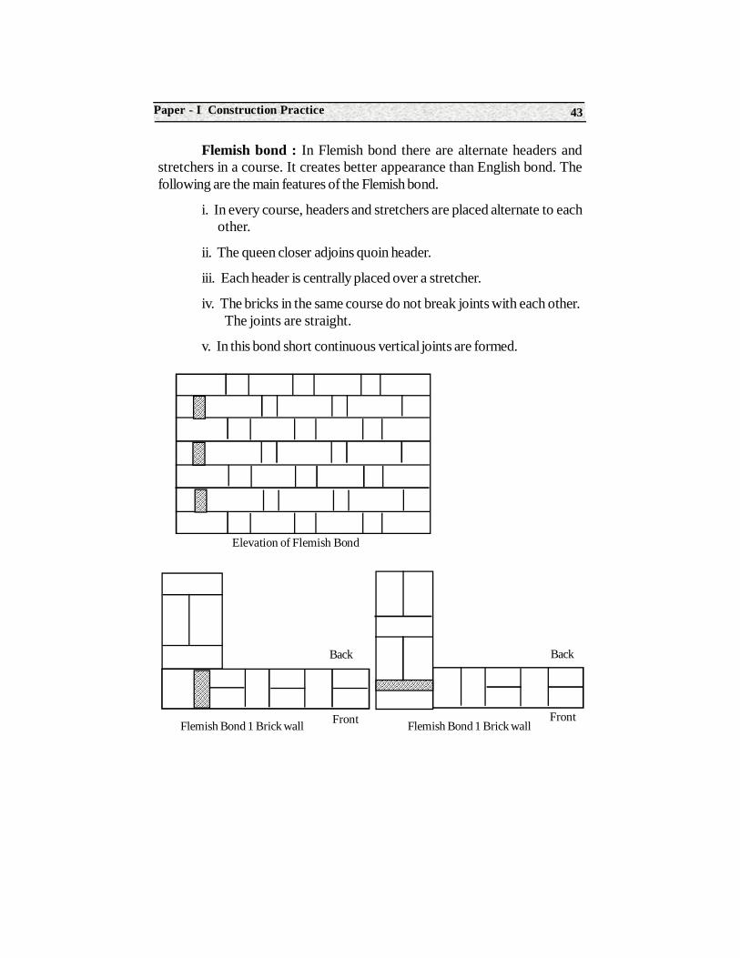
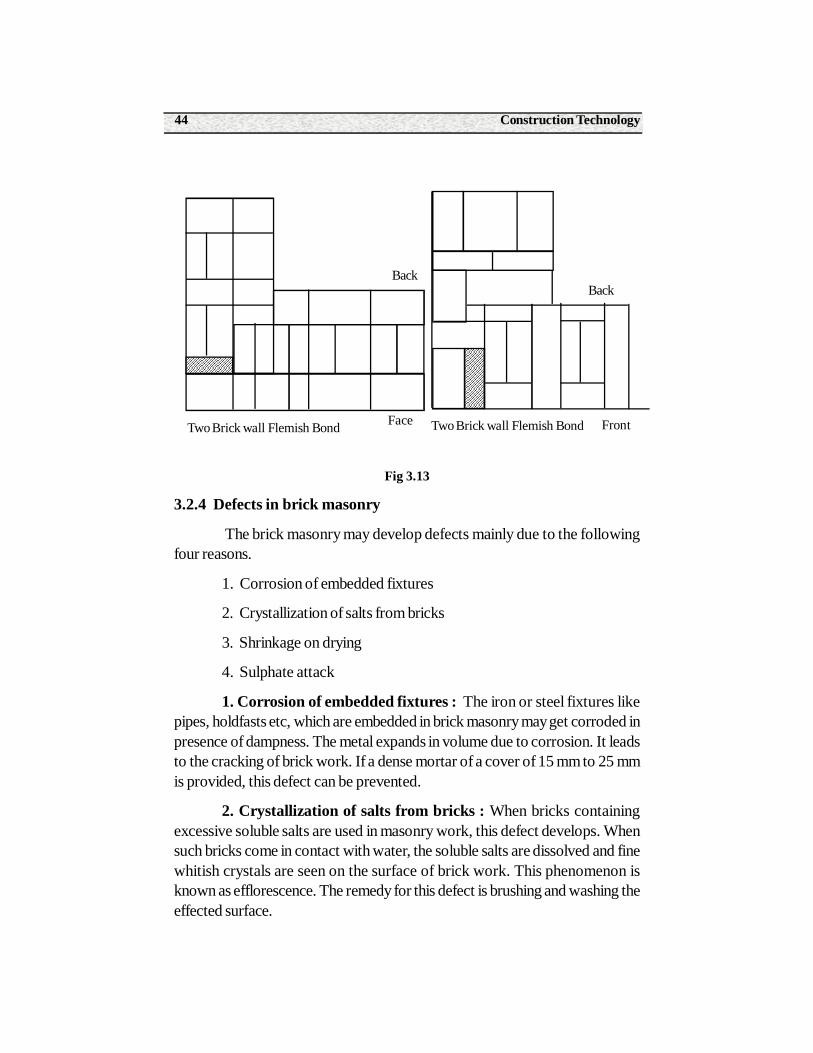
Flemish bond : In Flemish bond there are alternate headers andstretchers in a course. It creates better appearance than English bond. Thefollowing are the main features of the Flemish bond.
i. In every course, headers and stretchers are placed alternate to each other.
ii. The queen closer adjoins quoin header.
iii. Each header is centrally placed over a stretcher.
iv. The bricks in the same course do not break joints with each other. The joints are straight.
v. In this bond short continuous vertical joints are formed.
Back
Front
Back
Front
Elevation of Flemish Bond
Flemish Bond 1 Brick wall Flemish Bond 1 Brick wall
Construction Technology44
Fig 3.13
3.2.4 Defects in brick masonry
The brick masonry may develop defects mainly due to the followingfour reasons.
1. Corrosion of embedded fixtures
2. Crystallization of salts from bricks
3. Shrinkage on drying
4. Sulphate attack
1. Corrosion of embedded fixtures : The iron or steel fixtures likepipes, holdfasts etc, which are embedded in brick masonry may get corroded inpresence of dampness. The metal expands in volume due to corrosion. It leadsto the cracking of brick work. If a dense mortar of a cover of 15 mm to 25 mmis provided, this defect can be prevented.
2. Crystallization of salts from bricks : When bricks containingexcessive soluble salts are used in masonry work, this defect develops. Whensuch bricks come in contact with water, the soluble salts are dissolved and finewhitish crystals are seen on the surface of brick work. This phenomenon isknown as efflorescence. The remedy for this defect is brushing and washing theeffected surface.
Two Brick wall Flemish Bond
Back
FrontTwo Brick wall Flemish Bond
Back
Face
45Paper - I Construction Practice
3. Shrinkage on drying : The brick work normally swells with theabsorption of water and shrinks when the water evaporates. During the processof shrinkage, cracks are developed in the masonry. This defect can be preventedby using good quality of bricks.
4. Sulphate attack : The sulphate salts present in brick, react withalumina in the case of cement mortar. Similarly it will react with hydraulic lime inthe case of lime mortar. This results in increase in volume of the mortar. It leadsto chipping and spilling of bricks. The entry of water into the brick work shouldbe checked to prevent this defect.
3.2.5. Structures in brick masonry
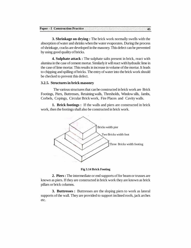
The various structures that can be constructed in brick work are BrickFootings, Piers, Buttresses, Retaining walls, Thresholds, Window sills, Jambs,Corbels, Copings, Circular Brick work, Fire Places and Cavity walls.
1. Brick footings : If the walls and piers are constructed in brickwork, then the footings shall also be constructed in brick work.
Fig 3.14 Brick Footing
2. Piers : The intermediate or end supports of for beam or trusses areknown as piers. If they are constructed in brick work they are known as brickpillars or brick columns.
3. Buttresses : Buttresses are the sloping piers to work as lateralsupports of the wall. They are provided to support inclined roofs, jack archesetc.
Bricks width pier
Two Bricks width foot
Three Bricks width footing
Construction Technology46
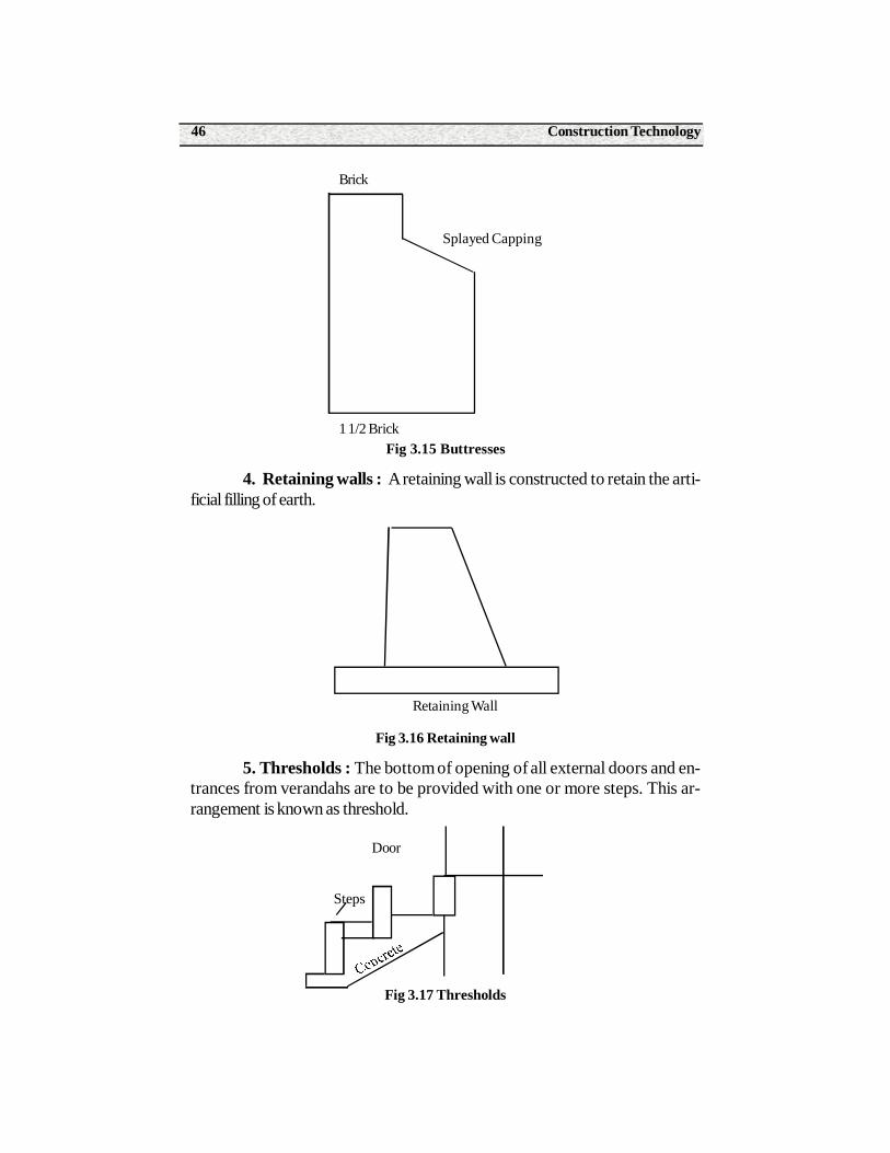
Fig 3.15 Buttresses
4. Retaining walls : A retaining wall is constructed to retain the arti-ficial filling of earth.
Fig 3.16 Retaining wall
5. Thresholds : The bottom of opening of all external doors and en-trances from verandahs are to be provided with one or more steps. This ar-rangement is known as threshold.
Fig 3.17 Thresholds
Brick
Splayed Capping
1 1/2 Brick
Retaining Wall
Door
Steps
47Paper - I Construction Practice
6. Window sill : In order to give a suitable finish to the windowopening and to protect the external below such opening, window sills areprovided. Window is placed over the window sill.
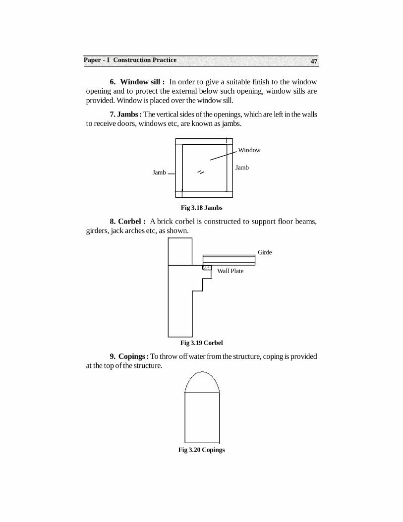
7. Jambs : The vertical sides of the openings, which are left in the wallsto receive doors, windows etc, are known as jambs.
Fig 3.18 Jambs
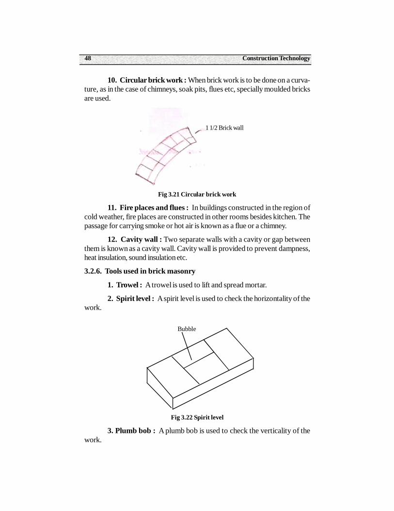
8. Corbel : A brick corbel is constructed to support floor beams,girders, jack arches etc, as shown.
Fig 3.19 Corbel
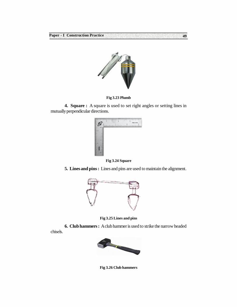
9. Copings : To throw off water from the structure, coping is providedat the top of the structure.
Fig 3.20 Copings
Jamb
Window
Jamb
Girde
Wall Plate
Construction Technology48
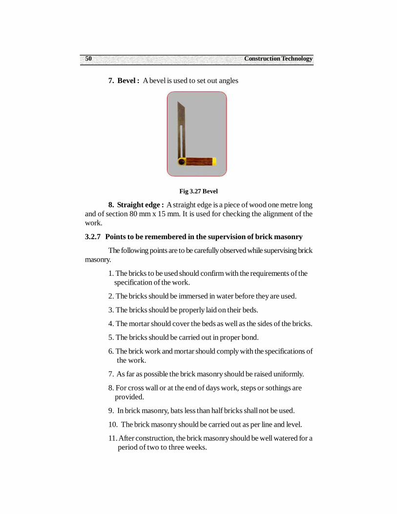
10. Circular brick work : When brick work is to be done on a curva-ture, as in the case of chimneys, soak pits, flues etc, specially moulded bricksare used.
Fig 3.21 Circular brick work
11. Fire places and flues : In buildings constructed in the region ofcold weather, fire places are constructed in other rooms besides kitchen. Thepassage for carrying smoke or hot air is known as a flue or a chimney.
12. Cavity wall : Two separate walls with a cavity or gap betweenthem is known as a cavity wall. Cavity wall is provided to prevent dampness,heat insulation, sound insulation etc.
3.2.6. Tools used in brick masonry
1. Trowel : A trowel is used to lift and spread mortar.
2. Spirit level : A spirit level is used to check the horizontality of thework.
Fig 3.22 Spirit level
3. Plumb bob : A plumb bob is used to check the verticality of thework.
1 1/2 Brick wall
Bubble
49Paper - I Construction Practice
Fig 3.23 Plumb
4. Square : A square is used to set right angles or setting lines inmutually perpendicular directions.
Fig 3.24 Square
5. Lines and pins : Lines and pins are used to maintain the alignment.
Fig 3.25 Lines and pins
6. Club hammers : A club hammer is used to strike the narrow headedchisels.
Fig 3.26 Club hammers
Construction Technology50
7. Bevel : A bevel is used to set out angles
Fig 3.27 Bevel
8. Straight edge : A straight edge is a piece of wood one metre longand of section 80 mm x 15 mm. It is used for checking the alignment of thework.
3.2.7 Points to be remembered in the supervision of brick masonry
The following points are to be carefully observed while supervising brickmasonry.
1. The bricks to be used should confirm with the requirements of the specification of the work.
2. The bricks should be immersed in water before they are used.
3. The bricks should be properly laid on their beds.
4. The mortar should cover the beds as well as the sides of the bricks.
5. The bricks should be carried out in proper bond.
6. The brick work and mortar should comply with the specifications of the work.
7. As far as possible the brick masonry should be raised uniformly.
8. For cross wall or at the end of days work, steps or sothings are provided.
9. In brick masonry, bats less than half bricks shall not be used.
10. The brick masonry should be carried out as per line and level.
11. After construction, the brick masonry should be well watered for a period of two to three weeks.
51Paper - I Construction Practice
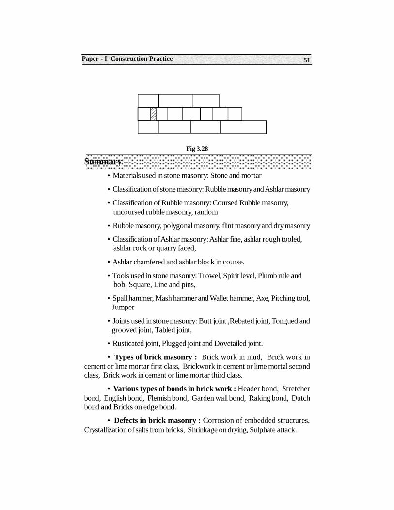
Fig 3.28
Summary• Materials used in stone masonry: Stone and mortar
• Classification of stone masonry: Rubble masonry and Ashlar masonry
• Classification of Rubble masonry: Coursed Rubble masonry, uncoursed rubble masonry, random
• Rubble masonry, polygonal masonry, flint masonry and dry masonry
• Classification of Ashlar masonry: Ashlar fine, ashlar rough tooled, ashlar rock or quarry faced,
• Ashlar chamfered and ashlar block in course.
• Tools used in stone masonry: Trowel, Spirit level, Plumb rule and bob, Square, Line and pins,
• Spall hammer, Mash hammer and Wallet hammer, Axe, Pitching tool, Jumper
• Joints used in stone masonry: Butt joint ,Rebated joint, Tongued and grooved joint, Tabled joint,
• Rusticated joint, Plugged joint and Dovetailed joint.
• Types of brick masonry : Brick work in mud, Brick work incement or lime mortar first class, Brickwork in cement or lime mortal secondclass, Brick work in cement or lime mortar third class.
• Various types of bonds in brick work : Header bond, Stretcherbond, English bond, Flemish bond, Garden wall bond, Raking bond, Dutchbond and Bricks on edge bond.
• Defects in brick masonry : Corrosion of embedded structures,Crystallization of salts from bricks, Shrinkage on drying, Sulphate attack.
Construction Technology52
• Structures in brick masonry : Brick footings, Piers, Buttresses,Retaining walls, Thresholds, Windows and sills, Jambs, Corbels, Copings,Circular brick works, Fire places and Cavity walls.
• Tools used in brick masonry : Trowel, Spirit level, Plumb bob,Square, Line and pins, Club hammer, Bevel and Straight edge.
Short Answer Type Questions1. Define stone masonry
2. What are the materials used in stone masonry.
3. What is Rubble masonry.
4. Define Ashlar masonry.
5. List out the classification of rubble masonry
6. List out the classification of Ashlar masonry.
7. What is a bond stone ?
8. In stone masonry, at what distance are bond stones provided.
9. List out the various tools used in stone masonry
10. What are the various types of joints used in stone masonry ?
11. Define brick masonry.
12. Define the following: Header, Stretcher, Queen closer, King closer, Frog, Bat.
13. List out the various types of brick masonry
14. List out the various types of bonds in brick masonry.
15. What is an english bond and a Flemish bond.?
16. What is the basic difference between an english bond and a Flemish bond ?
17. What are the various defects in brick masonry ?
18. Where do you provide a queen closer and a king closer.
19. Mention the various types of structures in brick masonry.
20. List out the various tools in brick masonry.
53Paper - I Construction Practice
21. What are the tools used for checking the horizontality and verticality of brick masonry ?
Long Answer type Questions1. What are the materials required for stone masonry?
2. How is stone masonry classified?
3. Describe the different forms of rubble masonry
4. Describe the different forms of ashlar masonry.
5. Describe the various types of joints used to secure the stones with each other.
6. What are the points to be observed while supervising the stone masonry ?
7. What are the various types of brick masonry ?
8. What are the characteristics of an english bond ?
9. Draw a neat sketch of the elevation of an english bond.
10. Draw a neat sketch of the plan of an odd course and even course of an english bond.
11. What are the characteristic of a Flemish bond?
12. Draw a neat sketch of an elevation of a Flemish bond.
13. Draw a neat sketch of the plan of an odd course and even course of a Flemish bond.
14. What are the various defects in brick masonry.
15. What are the points to be observed while supervising brick masonry?
Construction Technology54
Structure4.0 Introduction
4.1 Doors and Windows
4.2 Ventilators
Learning ObjectivesAfter completion of this unit, the student should be able to understand
the following.
• General terms used in doors and windows,
• Types of doors and their locations,
• Types of windows and their locations
• Fixtures and fastenings for doors and windows.
4.0 Introduction
Openings are provided in the structure for providing access to the usersof the structure, and for the purpose of providing day light, vision and ventilation.If the opening is provided for providing access to the users, it is a door. If theaccess is provided for the purpose of providing day light, air and ventilation, it isa window. Ventilators are provided above the top of the windows for ventilation.
4UNIT
Openings
55Paper - I Construction Practice
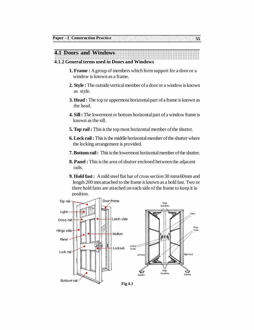
4.1 Doors and Windows4.1.2 General terms used in Doors and Windows
1. Frame : A group of members which form support for a door or a window is known as a frame.
2. Style : The outside vertical member of a door or a window is known as style.
3. Head : The top or uppermost horizontal part of a frame is known as the head.
4. Sill : The lowermost or bottom horizontal part of a window frame is known as the sill.
5. Top rail : This is the top most horizontal member of the shutter.
6. Lock rail : This is the middle horizontal member of the shutter where the locking arrangement is provided.
7. Bottom rail : This is the lowermost horizontal member of the shutter.
8. Panel : This is the area of shutter enclosed between the adjacent rails.
9. Hold fast : A mild steel flat bar of cross section 30 mmx60mm and length 200 mm attached to the frame is known as a hold fast. Two or three hold fasts are attached on each side of the frame to keep it in position.
Fig 4.1
Construction Technology56
10. Horn : The horizontal projection of the head or sill beyond the face of the frame is known as a horn. It helps in fixing t6he frame on the wall opening.
11.Shutter : The entire assembly of styles, panels and rails is known as the shutter.
12. Mullion : This is the vertical member at the centre which subdivides the door or window opening vertically.
13. Jamb : The vertical face of the opening which supports the frame of a door and window is known as the jamb.
4.1.3 Types of Doors
Depending upon the type of materials and the method of constructionthe various types of doors are as follows.
1. Battened, ledged and braced door
2. Panelled door
3. Glazed or sash door
4. Flush door
5. Louvered door
6. Collapsible door
7. Revolving door
8. Rolling shutter
9. Sliding door
10. Swing door
1. Battened Ledged and braced door : Battened, Ledged and braced
door is formed by joining vertical members known as battens, horizontal members
known as ledges and diagonal members known as braces. These members are
100 mm to 200 mm wide and 20 mm to 30 mm thick. They are hanged to the
supports with a T- Hinge. These doors are used for the purpose of privacy, but
they are not strong for security
57Paper - I Construction Practice
Fig 4.2
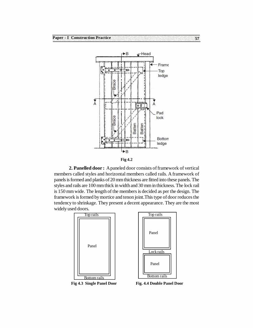
2. Panelled door : A paneled door consists of framework of verticalmembers called styles and horizontal members called rails. A framework ofpanels is formed and planks of 20 mm thickness are fitted into these panels. Thestyles and rails are 100 mm thick in width and 30 mm in thickness. The lock railis 150 mm wide. The length of the members is decided as per the design. Theframework is formed by mortice and tenon joint.This type of door reduces thetendency to shrinkage. They present a decent appearance. They are the mostwidely used doors.
Fig 4.3 Single Panel Door Fig. 4.4 Double Panel Door
Panel
Panel
Top rails
Lock rails
Bottom rails
Top rails
Panel
Bottom rails
Construction Technology58
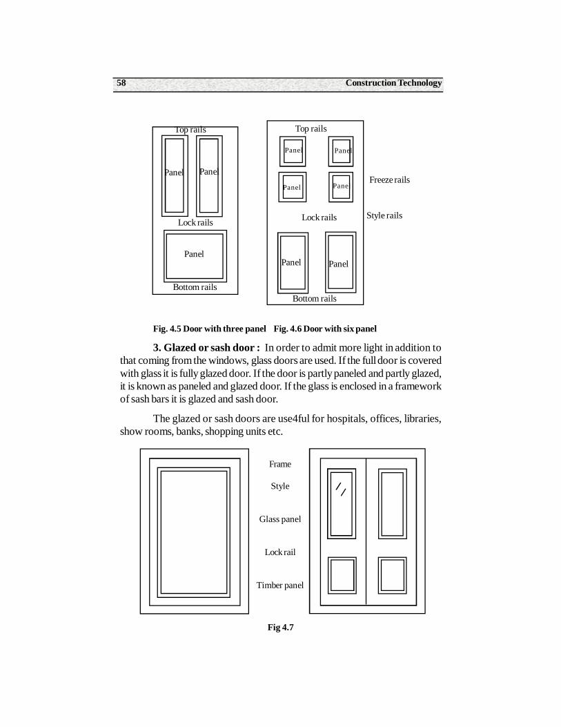
Fig. 4.5 Door with three panel Fig. 4.6 Door with six panel
3. Glazed or sash door : In order to admit more light in addition tothat coming from the windows, glass doors are used. If the full door is coveredwith glass it is fully glazed door. If the door is partly paneled and partly glazed,it is known as paneled and glazed door. If the glass is enclosed in a frameworkof sash bars it is glazed and sash door.
The glazed or sash doors are use4ful for hospitals, offices, libraries,show rooms, banks, shopping units etc.
Fig 4.7
Bottom rails
Top rails
Lock rails
Freeze rails
Style rails
Panel Panel
Panel
PanelPanel
Panel
Panel
Panel Panel
Top rails
Lock rails
Bottom rails
Frame
Style
Glass panel
Lock rail
Timber panel
59Paper - I Construction Practice
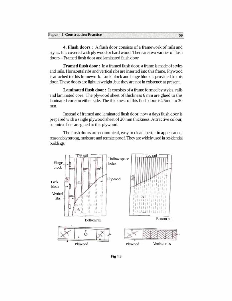
4. Flush doors : A flush door consists of a framework of rails andstyles. It is covered with ply wood or hard wood. There are two varities of flushdoors – Framed flush door and laminated flush door.
Framed flush door : In a framed flush door, a frame is made of stylesand rails. Horizontal ribs and vertical ribs are inserted into this frame. Plywoodis attached to this framework. Lock block and hinge block is provided to thisdoor. These doors are light in weight ,but they are not in existence at present.
Laminated flush door : It consists of a frame formed by styles, railsand laminated core. The plywood sheet of thickness 6 mm are glued to thislaminated core on either side. The thickness of this flush door is 25mm to 30mm.
Instead of framed and laminated flush door, now a days flush door isprepared with a single plywood sheet of 20 mm thickness. Attractive colour,sunmica shets are glued to this plywood.
The flush doors are economical, easy to clean, better in appearance,reasonably strong, moisture and termite proof. They are widely used in residentialbuildings.
Fig 4.8
Hingeblock
Lockblock
Verticalribs
Hollow spaceholex
Plywood
Bottom rail
Top rail
Bottom rail
Top rail
Plywood Plywood Vertical ribs
Construction Technology60
5. Louvered doors : In this types of doors, the shutters are providedwith inclined members known as louvers. The louvers are arranged at aninclination, such that horizontal vision is obstructed. However light and air passesthrough the gap between the louvers. The louvers are either fixed or movable.These doors allow free passage of air when closed and at the same time, maintainsufficient privacy. They are used for sanitary blocks.
6. Collapsible steel doors : A collapsible steel door consists of mildsteel frame. Two vertical pieces of mild steel channels are joined together with ahollow portion inside. Such pieces are spaced at 120 mm centre to centre andare joined by cross pieces. Rollers are mounted at the top and bottom of thevertical pieces. The door can be opened or closed by slightly pushing the handles.It is used at educational institutions and public places. Light and ventilation areprovided even when the doors are closed or opened.
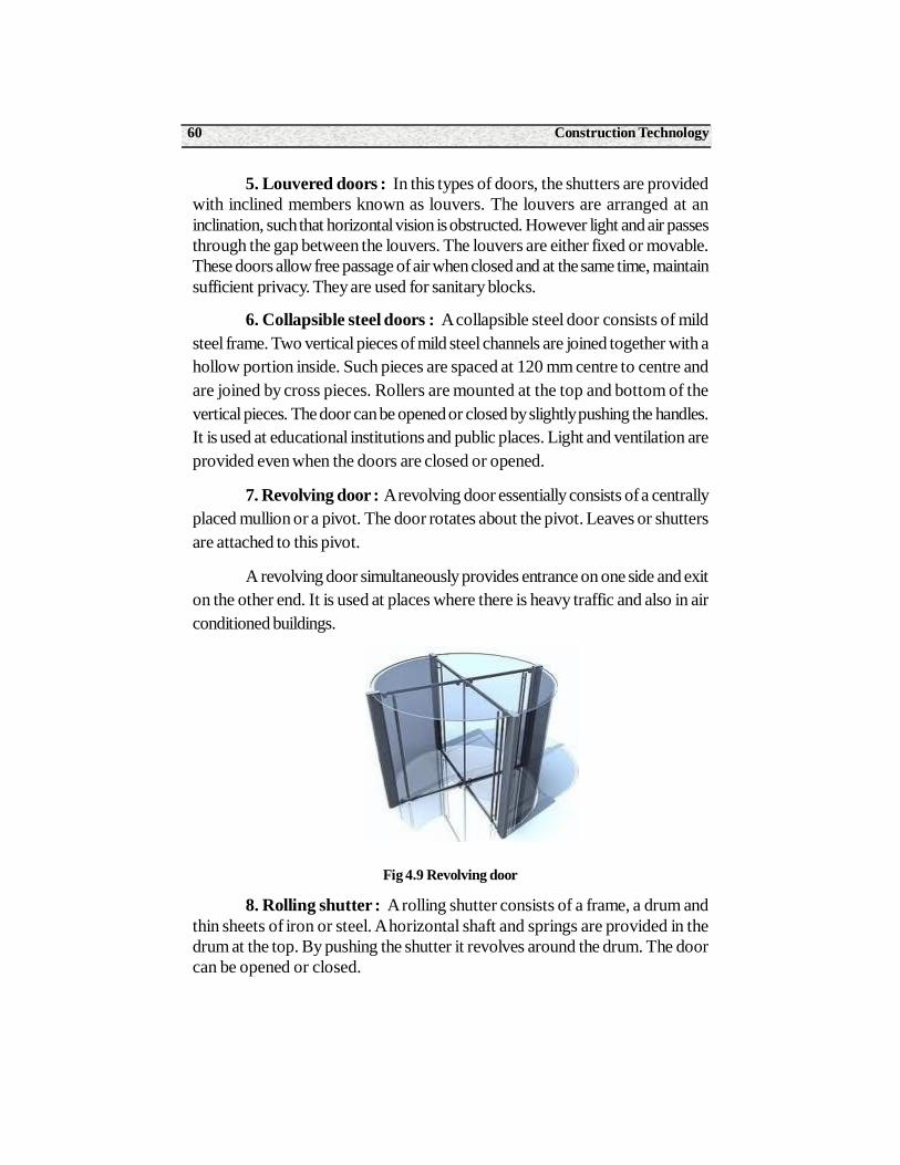
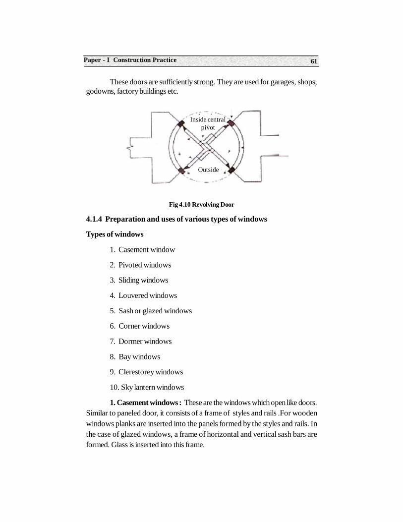
7. Revolving door : A revolving door essentially consists of a centrallyplaced mullion or a pivot. The door rotates about the pivot. Leaves or shuttersare attached to this pivot.
A revolving door simultaneously provides entrance on one side and exiton the other end. It is used at places where there is heavy traffic and also in airconditioned buildings.
Fig 4.9 Revolving door
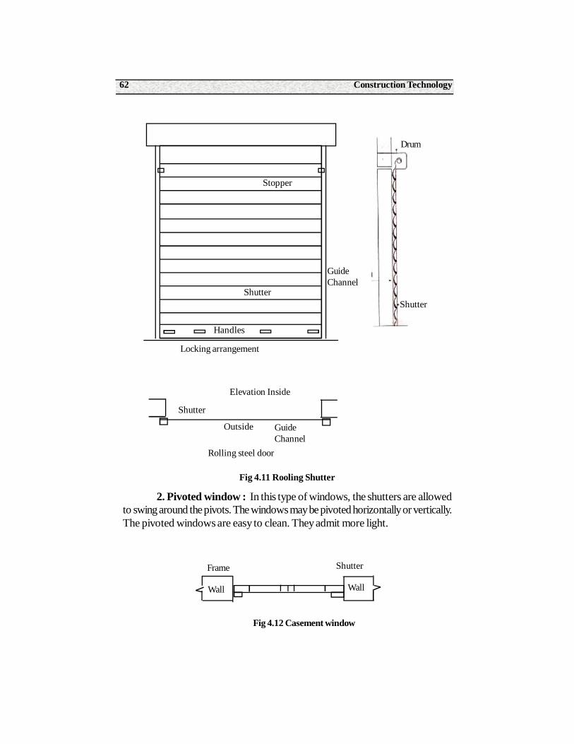
8. Rolling shutter : A rolling shutter consists of a frame, a drum andthin sheets of iron or steel. A horizontal shaft and springs are provided in thedrum at the top. By pushing the shutter it revolves around the drum. The doorcan be opened or closed.
61Paper - I Construction Practice
These doors are sufficiently strong. They are used for garages, shops,godowns, factory buildings etc.
Fig 4.10 Revolving Door
4.1.4 Preparation and uses of various types of windows
Types of windows
1. Casement window
2. Pivoted windows
3. Sliding windows
4. Louvered windows
5. Sash or glazed windows
6. Corner windows
7. Dormer windows
8. Bay windows
9. Clerestorey windows
10. Sky lantern windows
1. Casement windows : These are the windows which open like doors.Similar to paneled door, it consists of a frame of styles and rails .For woodenwindows planks are inserted into the panels formed by the styles and rails. Inthe case of glazed windows, a frame of horizontal and vertical sash bars areformed. Glass is inserted into this frame.
Inside centralpivot
Outside
Construction Technology62
Fig 4.11 Rooling Shutter
2. Pivoted window : In this type of windows, the shutters are allowedto swing around the pivots. The windows may be pivoted horizontally or vertically.The pivoted windows are easy to clean. They admit more light.
Fig 4.12 Casement window
Stopper
Shutter
GuideChannel
Handles
Locking arrangement
Elevation Inside
Shutter
Outside GuideChannel
Rolling steel door
Drum
Shutter
Frame
Wall Wall
Shutter
63Paper - I Construction Practice
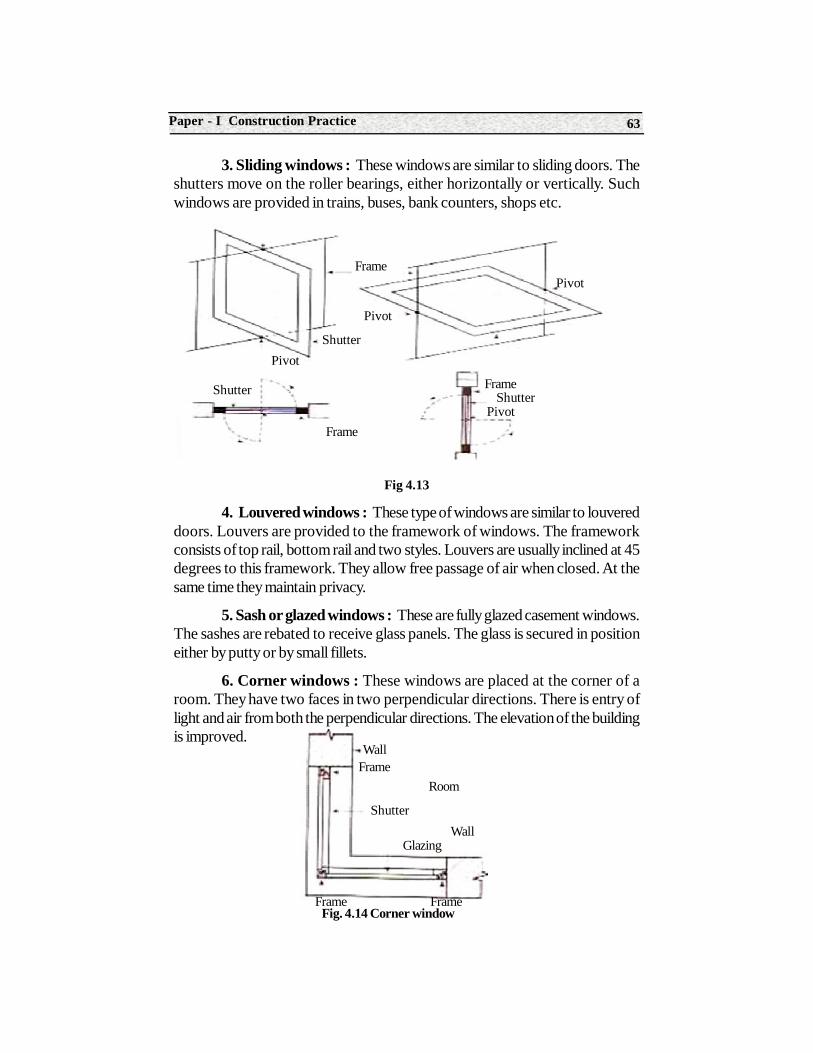
3. Sliding windows : These windows are similar to sliding doors. Theshutters move on the roller bearings, either horizontally or vertically. Suchwindows are provided in trains, buses, bank counters, shops etc.
Fig 4.13
4. Louvered windows : These type of windows are similar to louvereddoors. Louvers are provided to the framework of windows. The frameworkconsists of top rail, bottom rail and two styles. Louvers are usually inclined at 45degrees to this framework. They allow free passage of air when closed. At thesame time they maintain privacy.
5. Sash or glazed windows : These are fully glazed casement windows.The sashes are rebated to receive glass panels. The glass is secured in positioneither by putty or by small fillets.
6. Corner windows : These windows are placed at the corner of aroom. They have two faces in two perpendicular directions. There is entry oflight and air from both the perpendicular directions. The elevation of the buildingis improved.
Frame
Frame
Pivot
ShutterPivot
Shutter
Frame
Pivot
PivotShutter
WallFrame
Room
Shutter
Frame
GlazingWall
FrameFig. 4.14 Corner window
Construction Technology64
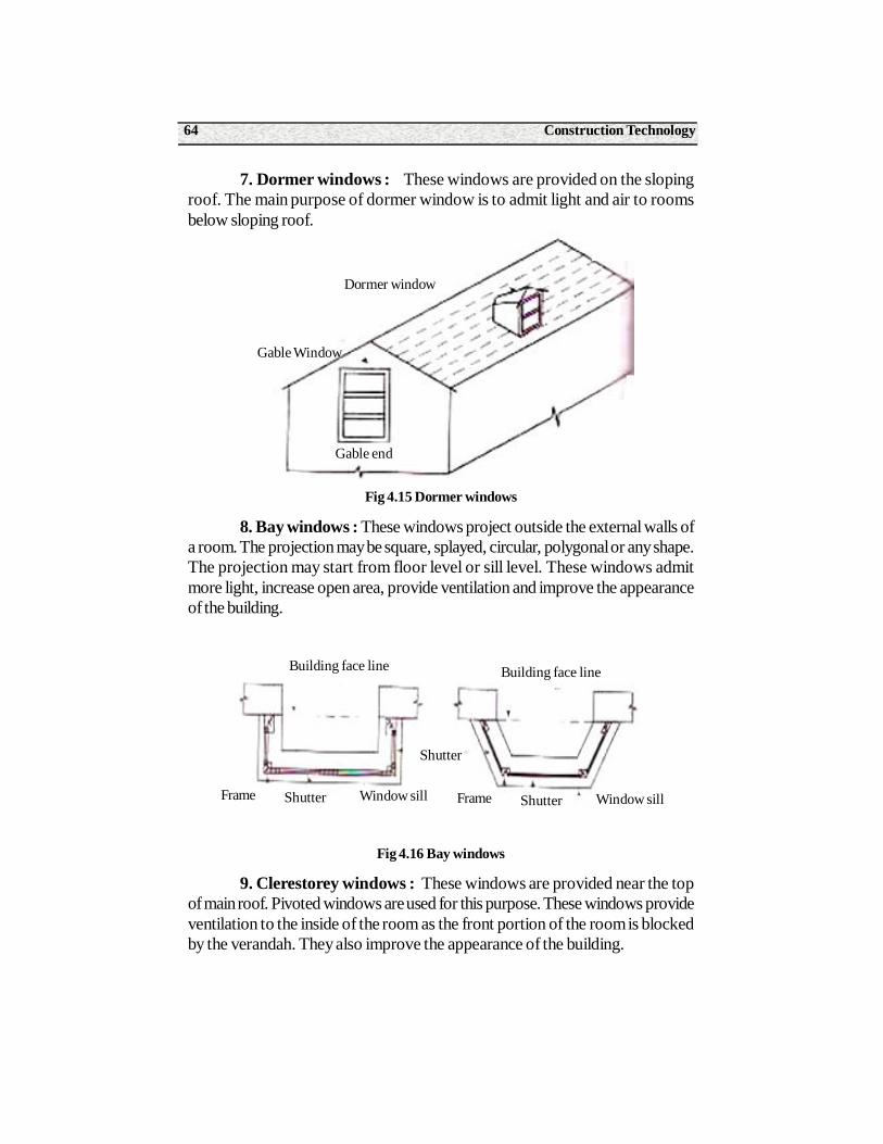
7. Dormer windows : These windows are provided on the slopingroof. The main purpose of dormer window is to admit light and air to roomsbelow sloping roof.
Fig 4.15 Dormer windows
8. Bay windows : These windows project outside the external walls ofa room. The projection may be square, splayed, circular, polygonal or any shape.The projection may start from floor level or sill level. These windows admitmore light, increase open area, provide ventilation and improve the appearanceof the building.
Fig 4.16 Bay windows
9. Clerestorey windows : These windows are provided near the topof main roof. Pivoted windows are used for this purpose. These windows provideventilation to the inside of the room as the front portion of the room is blockedby the verandah. They also improve the appearance of the building.
Dormer window
Gable end
Gable Window
Frame Shutter Window sill
Building face line Building face line
Shutter
Frame Shutter Window sill
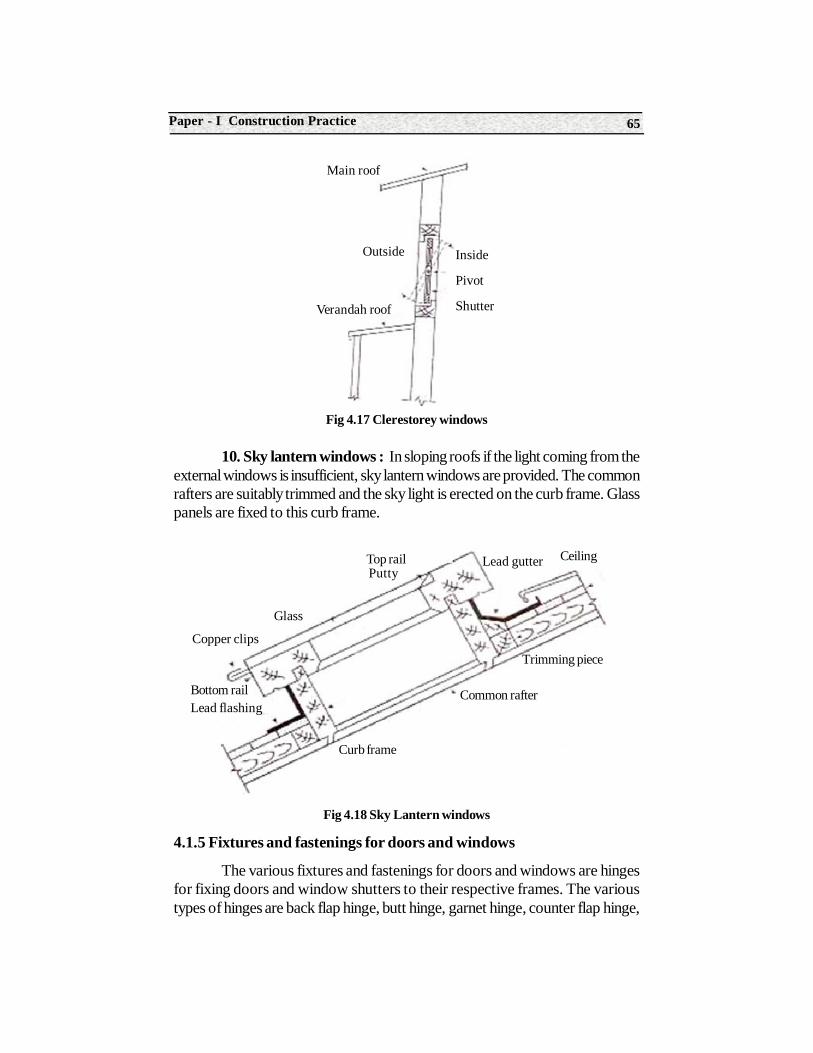
65Paper - I Construction Practice
Fig 4.17 Clerestorey windows
10. Sky lantern windows : In sloping roofs if the light coming from theexternal windows is insufficient, sky lantern windows are provided. The commonrafters are suitably trimmed and the sky light is erected on the curb frame. Glasspanels are fixed to this curb frame.
Fig 4.18 Sky Lantern windows
4.1.5 Fixtures and fastenings for doors and windows
The various fixtures and fastenings for doors and windows are hingesfor fixing doors and window shutters to their respective frames. The varioustypes of hinges are back flap hinge, butt hinge, garnet hinge, counter flap hinge,
Main roof
Outside Inside
Pivot
ShutterVerandah roof
Glass
Top railPutty
Lead gutter Ceiling
Trimming piece
Common rafter
Curb frame
Bottom railLead flashing
Copper clips
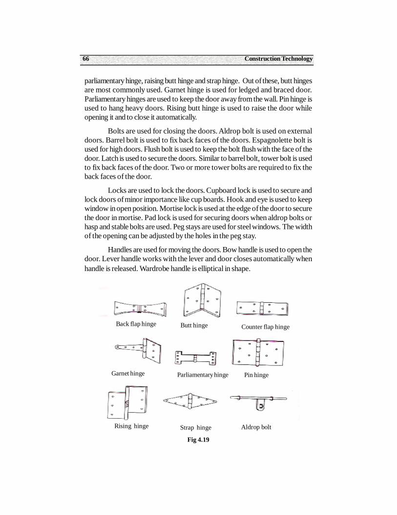
Construction Technology66
parliamentary hinge, raising butt hinge and strap hinge. Out of these, butt hingesare most commonly used. Garnet hinge is used for ledged and braced door.Parliamentary hinges are used to keep the door away from the wall. Pin hinge isused to hang heavy doors. Rising butt hinge is used to raise the door whileopening it and to close it automatically.
Bolts are used for closing the doors. Aldrop bolt is used on externaldoors. Barrel bolt is used to fix back faces of the doors. Espagnolette bolt isused for high doors. Flush bolt is used to keep the bolt flush with the face of thedoor. Latch is used to secure the doors. Similar to barrel bolt, tower bolt is usedto fix back faces of the door. Two or more tower bolts are required to fix theback faces of the door.
Locks are used to lock the doors. Cupboard lock is used to secure andlock doors of minor importance like cup boards. Hook and eye is used to keepwindow in open position. Mortise lock is used at the edge of the door to securethe door in mortise. Pad lock is used for securing doors when aldrop bolts orhasp and stable bolts are used. Peg stays are used for steel windows. The widthof the opening can be adjusted by the holes in the peg stay.
Handles are used for moving the doors. Bow handle is used to open thedoor. Lever handle works with the lever and door closes automatically whenhandle is released. Wardrobe handle is elliptical in shape.
Fig 4.19
Back flap hinge Butt hinge Counter flap hinge
Garnet hinge Parliamentary hinge Pin hinge
Rising hinge Strap hinge Aldrop bolt
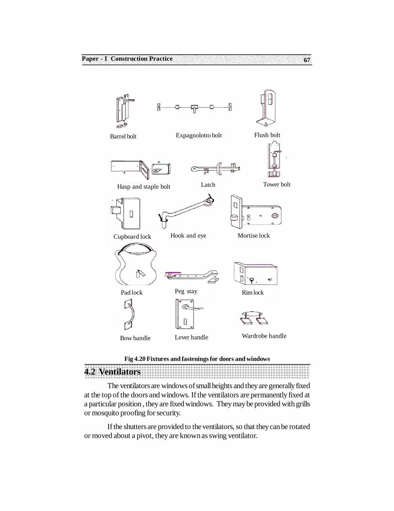
67Paper - I Construction Practice
Fig 4.20 Fixtures and fastenings for doors and windows
4.2 VentilatorsThe ventilators are windows of small heights and they are generally fixed
at the top of the doors and windows. If the ventilators are permanently fixed ata particular position , they are fixed windows. They may be provided with grillsor mosquito proofing for security.
If the shutters are provided to the ventilators, so that they can be rotatedor moved about a pivot, they are known as swing ventilator.
Latch Tower bolt
Cupboard lock Hook and eye Mortise lock
Pad lock Peg stay Rim lock
Barrel bolt Expagnolotto bolt Flush bolt
Hasp and staple bolt
Bow bandle Lever handle Wardrobe handle
Construction Technology68
Summary1. An opening for providing access to users is a door.
2. An opening for providing day light, air and ventilation is known as ventilator.
3. The component parts used in doors and windows are frame, style, head, sill, top rail, lock rail, bottom rail, panel, hold fast, horn, shutter, million and jamb.
4. The various types of doors are battened, ledged and braced door, paneled door, glazed or sash door, flush door, louvered door, collapsible door, revolving door, rolling shutter, sliding door and swing door.
5. The various types of windows are casement window, pivoted window, sliding window, louvered window, sash or glazed windows, corner window, dormer window, bay window, clerestorey window, sky lantern window.
6. The various fixtures and fastenings to doors and windows are hinges, bolts, locks and handles.
7. Ventilators are provided above the doors and window openings. There are fixed ventilators and swinging ventilators.
Short Answer Type Questions1. What is an opening ?
2. Define the following terms frame, style, head, sill, rail, panel, horn, shutter, mullion.
3. List out the various types of doors.
4. Where do you provide a louvered door.
5. What type of door is provided for air conditioned buildings and for controlling heavy traffic ?
6. List out the various types of windows.
7. Where do you provide sliding windows.
8. What is the advantage of a bay window ?
9. List out the various types of fixtures and fastenings for doors and windows.
69Paper - I Construction Practice
10. What are the various types of ventilators ?
Long Answer Type Questions1. What are the various types of doors? Describe any two.
2. Draw a neat sketch of a paneled door. Describe any four parts.
3. What are the various types of windows ? Describe any two.
O.J.T. Questions
1. Calculate the quantity of wood work required for a paneled door.
2. Calculate the quantity of wood and glass required for glazed and casement window.
3. Identify the different types of wood, glass and various accessories required for doors and Windows.
Construction Technology70
Structure5.0 Introduction
5.1 Types of Lintels
5.2 Sunshade
Learning ObjectivesAfter completion of this unit, the student should be able to understand
• The necessity of lintel, various types of lintel,
• Definition of the sunshade,
• Types of ventilators.
IntroductionTo construct above doors and window openings, arches and lintels are
used. Even from stone age, different materials are used to support the constructionabove these openings. Various types of arches are also used to span over theseopenings. Due to its ease in construction lintels are preferred. At present lintels,especially R.C.C. lintels are widely used in construction.
Definition : A lintel is a horizontal member which is placed across anopening to support the portion of the structure above it.
5UNIT
Lintels
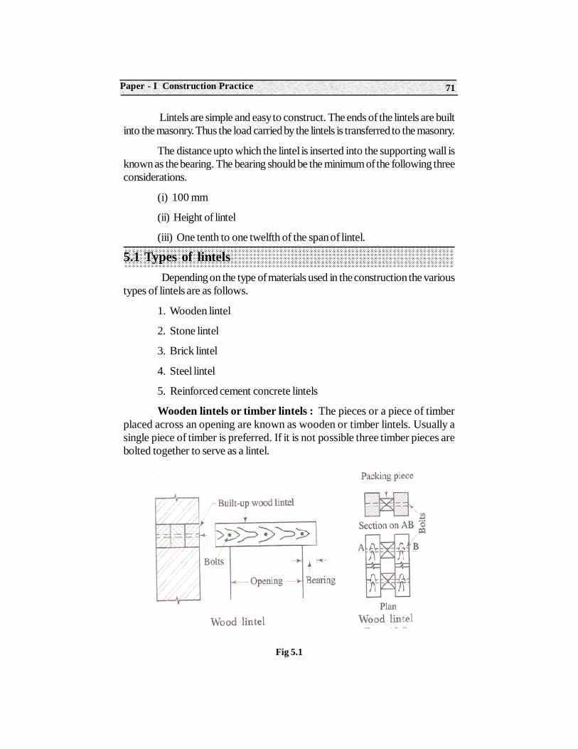
71Paper - I Construction Practice
Lintels are simple and easy to construct. The ends of the lintels are builtinto the masonry. Thus the load carried by the lintels is transferred to the masonry.
The distance upto which the lintel is inserted into the supporting wall isknown as the bearing. The bearing should be the minimum of the following threeconsiderations.
(i) 100 mm
(ii) Height of lintel
(iii) One tenth to one twelfth of the span of lintel.
5.1 Types of lintels Depending on the type of materials used in the construction the various
types of lintels are as follows.
1. Wooden lintel
2. Stone lintel
3. Brick lintel
4. Steel lintel
5. Reinforced cement concrete lintels
Wooden lintels or timber lintels : The pieces or a piece of timberplaced across an opening are known as wooden or timber lintels. Usually asingle piece of timber is preferred. If it is not possible three timber pieces arebolted together to serve as a lintel.
Fig 5.1
Construction Technology72
Advantages
1. The wooden lintel helps in securing the heads of the frames of the doors and windows in position.
2. These are light in weight.
Disadvantages
1. The wooden lintels are comparatively weak in strength.
2. The wooden lintels are liable to be destroyed by fire and are also l liable to decay.
3. The wooden lintels are very costly.
Uses
The wooden lintels are used in hilly areas, where wood is easily available.
Stone lintels : These lintels consists of slabs of stones which are placedacross the openings. The stone lintels may be formed by a single piece or morethan one piece.
Advantages
1. It is easy to dress a stone.
2. It is possible to have architectural appearance.
Disadvantages
1. The stone possesses low tensile resistance.
2. The stone cracks when subjected to vibratory loads.3
3. It is difficult to obtain stones of required depth.
Uses
The stone lintels is used at places where stone slabs are easily available.It can be used for slabs upto 1 m span.
Brick lintels : A brick lintel is constructed by placing the bricks on endor edge. A temporary wood support is necessary to construct a brick lintel. Thebrick lintel should have a depth of multiples of the thickness of the brick.
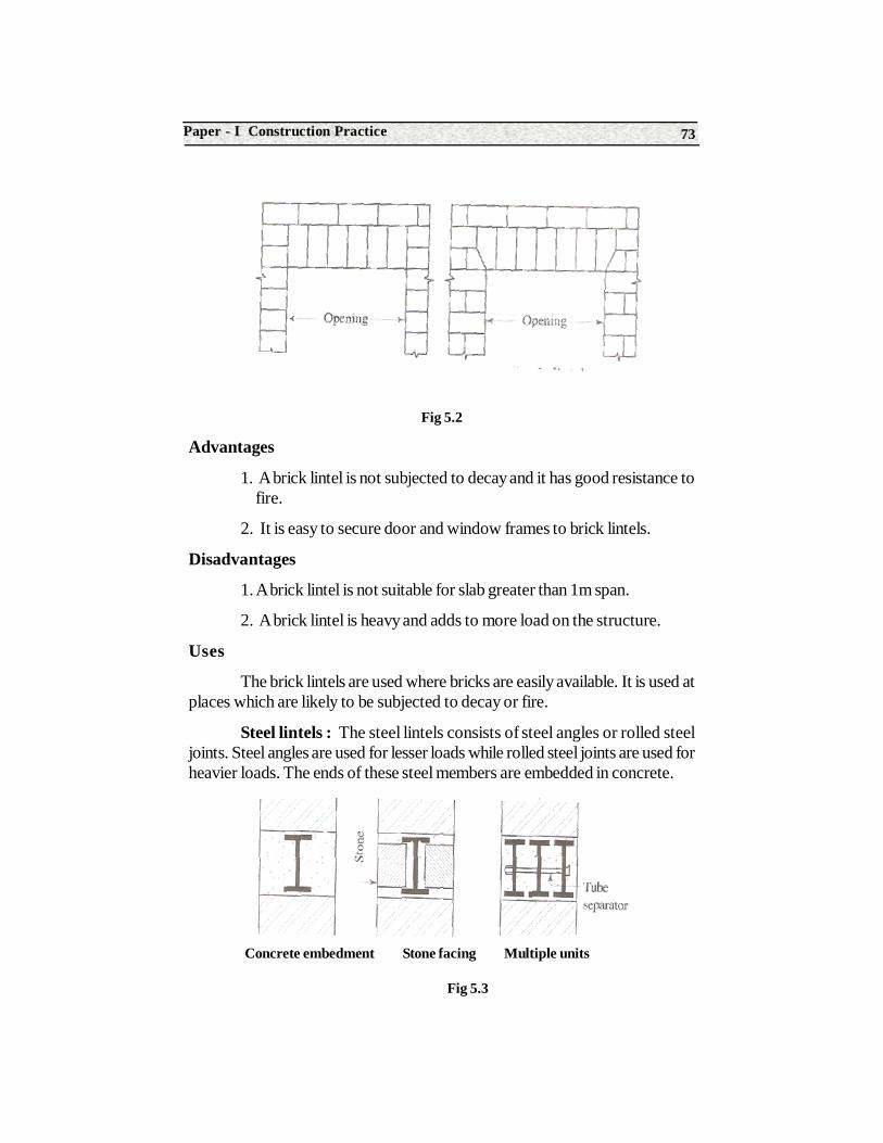
73Paper - I Construction Practice
Fig 5.2
Advantages
1. A brick lintel is not subjected to decay and it has good resistance to fire.
2. It is easy to secure door and window frames to brick lintels.
Disadvantages
1. A brick lintel is not suitable for slab greater than 1m span.
2. A brick lintel is heavy and adds to more load on the structure.
Uses
The brick lintels are used where bricks are easily available. It is used atplaces which are likely to be subjected to decay or fire.
Steel lintels : The steel lintels consists of steel angles or rolled steeljoints. Steel angles are used for lesser loads while rolled steel joints are used forheavier loads. The ends of these steel members are embedded in concrete.
Fig 5.3
Concrete embedment Stone facing Multiple units
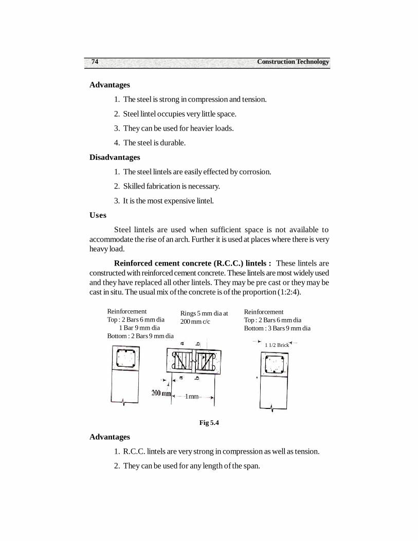
Construction Technology74
Advantages
1. The steel is strong in compression and tension.
2. Steel lintel occupies very little space.
3. They can be used for heavier loads.
4. The steel is durable.
Disadvantages
1. The steel lintels are easily effected by corrosion.
2. Skilled fabrication is necessary.
3. It is the most expensive lintel.
Uses
Steel lintels are used when sufficient space is not available toaccommodate the rise of an arch. Further it is used at places where there is veryheavy load.
Reinforced cement concrete (R.C.C.) lintels : These lintels areconstructed with reinforced cement concrete. These lintels are most widely usedand they have replaced all other lintels. They may be pre cast or they may becast in situ. The usual mix of the concrete is of the proportion (1:2:4).
Fig 5.4
Advantages
1. R.C.C. lintels are very strong in compression as well as tension.
2. They can be used for any length of the span.
ReinforcementTop : 2 Bars 6 mm dia 1 Bar 9 mm diaBottom : 2 Bars 9 mm dia
Rings 5 mm dia at200 mm c/c
ReinforcementTop : 2 Bars 6 mm diaBottom : 3 Bars 9 mm dia
1 1/2 Brick
1 mm
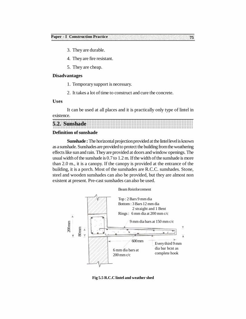
75Paper - I Construction Practice
3. They are durable.
4. They are fire resistant.
5. They are cheap.
Disadvantages
1. Temporary support is necessary.
2. It takes a lot of time to construct and cure the concrete.
Uses
It can be used at all places and it is practically only type of lintel inexistence.
5.2. SunshadeDefinition of sunshade
Sunshade : The horizontal projection provided at the lintel level is knownas a sunshade. Sunshades are provided to protect the building from the weatheringeffects like sun and rain. They are provided at doors and window openings. Theusual width of the sunshade is 0.7 to 1.2 m. If the width of the sunshade is morethan 2.0 m., it is a canopy. If the canopy is provided at the entrance of thebuilding, it is a porch. Most of the sunshades are R.C.C. sunshades. Stone,steel and wooden sunshades can also be provided, but they are almost nonexistent at present. Pre-cast sunshades can also be used.
Fig 5.5 R.C.C lintel and weather shed
Beam Reinforcement
Top : 2 Bars 9 mm diaBottom : 3 Bars 12 mm dia 2 straight and 1 BentRings : 6 mm dia at 200 mm c/c
9 mm dia bars at 150 mm c/c
Every third 9 mmdia bar bcnt ascomplete hook
6 mm dia bars at200 mm c/c
600 mm
200 m
m
80 m
m
Construction Technology76
SummaryLintels are provided at the openings to support construction above the
openings. The various types of lintels are wooden lintel, stone lintel, brick lintel,steel lintel and R.C.C. lintel. Sunshades are provided at the lintel level to protectthe building from rain and sun.
Short Answer Type Questions1. What is a lintel
2. List out the various types of lintels.
3. Define sunshade.
4. Where do you prefer a steel lintel ?
Long Answer Type Questions1. What are the various types of lintels. ? Write briefly any two types with advantages, disadvantages and uses.
O.J.T. Questions
1. Note down the size of the openings, thickness of the lintels and thesize of the sunshades.
Structure6.0. Introduction
6.1. General terms involved in floors.
6.2. Various types of floors.
6.3. Materials required for cement concrete, terrazzo, mosaic and stone slab floors
6.4. Method of construction of cement concrete, mosaic, terrazzo and marble floors
Learning ObjectivesAfter completion of this unit the student shall be able to understand the following
General terms used in floors, preparation and uses of various types offloors, materials required for cement concrete, terrazo, mosaic and stones labfloors, methods of construction of various type sof floors.
6.0 IntroductionIn order to sub-divide the portion between the plinth level and roof level
solid constructions are carried out. These constructions are known as floors.The exposed top surfaces of the floors are known as floorings. If the building ismulti storied, there will be floors at each stories of the building. Depending onthe requirements different types of floorings can be selected.
6UNIT
Floors
Construction Technology78
6.1 General terms involved in floorsFloor : The sub-division of the building into plinth level, roof level and
subsequent roof levels are known as floors. The floors are mentioned as groundfloor, first floor, second floor etc.
Floorings : The exposed top surface of the floors are known asfloorings. The floorings are indicated by the type of material and the workmanshipused for the floor.
Plinth : The vertical height of the building from the ground level to thebasement level is known as a plinth.
Sand filling : The height of the sand in foundation from ground level tothe basement level is known as sand filling. The building is divided into roomsand each room is filled with sand from ground level to basement.
Sub base : Over the sand filling a layer of plain cement concrete(1:5:10)of 100 mm thickness is laid and compacted. This layer of concrete is known assub base.
Base course : Over the sub base course, a layer of plain cementconcrete (1:2:4) is laid and compacted. This layer is known as base course. Theflooring with different materials is laid over this base course.
Finishing course : The final layer of the flooring with the respectiveflooring material is known as the finishing course.
6.2 Various types of floors Basically the floors are classified as timber floors and composite floors.
Floors composed of more than one material are composite floors. The varioustypes of composite floors are Double flagstone floors, Filler joist floors, Jackarch floors, R.C.C. floors and hollow block and rib floors. Due to scarcity andhigh cost of timber, these floors are not in existence at present. The compositefloors mentioned are constructed when Reinforced Cement Concrete is not inexistence. They are not used in construction at present. The following floors areextensively used at present. Cement concrete flooring, Mosaic flooring, Terrazzoflooring and marble flooring depending on the type of flooring material used.
Factors affecting choice of flooring material : The following factorsare to be carefully considered before selecting the material for flooring of aparticular building.
1. Appearance : The flooring material should be of desired appearance.It should produce the color effect in conformity with the use of the building.
79Paper - I Construction Practice
2. Cleaning : The flooring material should be such that it can be easily and effectively cleaned.
3. Comfort : The flooring material should be such that it gives desired comfort when it is put to use.
4. Cost : The cost of flooring material should be reasonable as compared to the utility of the building.
5. Durability : The flooring material should be durable. It should be strong enough to resist wear and tear, chemical action etc.
6. Noise : If silence is required, such flooring material which makes less noise should be preferred.
7. Slipperiness : The surface of the floor should not be too slippery. It is dangerous especially for old people, children and pregnant women.
6.3 Materials required for Cement concrete, Terrazzo, Mosaic, Marble and Stone slab floors.
Cement concrete Flooring : In cement concrete flooring, the thicknessof the concrete layer is 40 mm. The proportions of this concrete consists of 1part of cement, 2 parts of sand and 4 parts of coarse aggregate by volume. Thesize of the coarse aggregate varies from 20 mm to 6 mm. Over this layer ofconcrete, cement and sand mortar of proportion 1:3 is laid for a thickness of 20mm. Over this cement sand layer, cement slurry is poured and it is smoothlyfinished with a trowel. It is cheap and it is used when cost factor is to beconsidered.
Terrazzo flooring : This is also a type of concrete flooring in which,marble chips are used as aggregates, marble powder as fine aggregate andcement. The proportion of marble chips and cement is 1:2 to 1:3. Any desiredcolor may be obtained by using different colors of marble chips. If ordinaryPortland cement is used only one color background of grey is obtained. If differentcolor background is required, then white cement should be used instead ofordinary Portland cement. By mixing different color oxides with white cementwe get the desired color of the floor.
After laying and watering for at least 7 days, polishing is carried out.First coat of polishing is done by coarse carborundum. Second coat is done byfinely grained carborundum stone. Third coat is done by pumice stone. Finalcoat of polish is done by oxalic acid and wax. It can be used for residentialbuildings. As it is not as expensive as tiles and marbles it can be used be used forpublic places where cost factor is involved.
Construction Technology80
Mosaic flooring : Mosaic is a picture or pattern produced by fittingtogether small coloured pieces of stone. Precast tiles with marble chips at thetop surface, known as mosaic tiles are used. In terrazzo flooring concrete layeris formed with marble chips where as in mosaic flooring mosaic tiles are laid.Polishing done after laying the tiles in position. As in terrazzo flooring, first coatof polishing is done by coarse carborundum stone, second coating with finelygrained carborundum stone, third coating with pumice stone. Final coat of polishis applied with oxalic acid and wax. If glazed tiles are used, polishing is notrequired.
Marble and stone slab flooring : This type of flooring is used forsuperior work. It is especially used where cleanliness is required as in the caseof operation theatres in hospitals, temples etc. Depending on the origin of itsformation, different colors and different color shades are obtained. Even stoneslabs of same geologic origin may have different color shades. Some stone slabsare polished and laid. But stone slabs of marble are laid, well watered for 7 daysand they are polished. First coat of polishing is done with coarse carborundum,second coat with finely grained carborundum stone and third coat with pumicestone. Finally a coat of wax polish. At present seven coats of polishing is beingdone with coarse grained carborundum, fine grained carborundum and pumicestones.
6.4 Method of construction of Cement concrete, Mosaic, Terrazzo and Marble floors
Cement Concrete Flooring : Plain cement concrete of 1 part ofcement, 2 parts of sand and 4 parts of coarse aggregate is laid for a thickness of40 mm, over mass concrete (1:5:10). Over this layer a layer of cement sandmortar (1:3) is to be laid. To mark the gradient of the floor, cement sand mortaris initially laid at the corners of the room. The thickness of this layer is 20 mm. Tomaintain the gradient, more thickness is laid at the higher edges. A thin rope isplaced on the opposite corners of the heap and the gradient is marked on theentire length by placing heaps of mortar under the thin rope. As per the gradientmarked the entire area of floor is filled with the cement sand mortar. It is neatlytrowelled as per the set gradient. Over this cement slurry is poured and it isneatly finished with a smooth trowel.
Mosaic Flooring : Pre-cast concrete tiles with mosaic chips at topsurface, known as mosaic tiles are manufactured at the factory. They are availablein standard sizes. These tiles are laid over a plain cement concrete of 20 mmthickness. Initially a border line is laid with plain colored tiles around the surface.The gradient is set while laying this border line. Cement mortar is placed belowthese tiles and the alignment of the surface is set. The remaining surfaced is filled
81Paper - I Construction Practice
with tiles and cement mortar is placed below these tiles. After laying these tiles,they are well watered for 7 days. Carborandum stone is fixed to the polishingmachine and it is run over the surface, leading to a first coat of polish. Similarlyfinely grained carborundum stone and pumice stones are placed under themachine and run over second and third coat of polishing. Finally oxalic acid andwax polishing is applied with the machine.
Terrazzo Flooring : Cement and marble chips are mixed to a proportionof 1:2 to 1:3. Enough water is added to this dry mixture and a paste is formed.As per the color back ground, different color chips, color acids and white cementare used. The mixture is laid over a sound and rough base. Initially a border stripis laid as per the required gradient. The remaining mixture is laid in between theborder strip. This base is kept watered for 7 days. First coat of polishing is doneby coarse carborundum stone. Second coat of polishing is done by finely grainedcarborundum stone and third coat of polishing with pumice stone. Polishing maybe done with hand or with machine. Final coat of polish is applied with a wax.
Marble Flooring : Plain cement concrete(1:2:4) is laid over the subbase. To mark the alignment of the gradient, cement sand mortar heaps areplaced at the corners of the room. Marble slabs are placed over these heapsand the gradient of the floor is checked. A thin rope is placed over these marbleslabs. The remaining slabs are placed over the cement mortar as per the gradientset by this rope. After watering these marble slabs for 7 days, polishing is done.As in other types of flooring three coats of polishing and final coat of polishingwith wax may be done. The present trend is to undertake seven to ten coats ofpolishing. The polishing coat with wax is avoided. This procedure of flooringmay be continued for other stone slabs like cuddapah slabs and tiles. The methodsof polishing is different for other types of slabs. Polishing is not required for tiles.
Summary• The sub-division of the building into different levels is a floor while the exposed surface of the floors is known as the flooring.
• Sub- base is mass concrete (1:5:10) of 100 mm thickness.
• Base course is plain cement concrete (1:2:4) of 20 mm thickness.
• The factors affecting the choice of flooring material are appearance, cleaning, comfort, cost, durability noise and slipperiness.
• The various types of floorings are cement concrete flooring, mosaic flooring, terrazzo, marble and stone slab floors.
Construction Technology82
Short Answer Type Questions1. Define floors and flooring.
2. List out the various types of floors.
3. What are the materials used in cement concrete flooring?
4. What are the materials used in terrazzo flooring?
5. Mention the various types of stones used in polishing the floors.
6. What are the factors affecting the choice of flooring material?
Long Answer Type Questions1. What are the factors to be considered in deciding the choice of flooring material ?
2. Describe the materials required for terrazzo flooring.
3. Write briefly the procedure of construction of cement concrete flooring
4. Write briefly the procedure of construction marble floors.
5. Write short notes on mosaic flooring
6. Write short notes on stone slab flooring
OJT Questions
Identify the different floors used at different places.
Structure7.0 Introduction
7.1 Definition of roofs and the concept of roofs.
7.2 Classification of roofs, various types of pitched roofs, king post truss and queen post truss.
7.3 Steel trusses – various parts of steel truss, panels for different spans.
7.4 Roof covering material for pitched roofs, flat roof and R.C.C. roof.
7.5 Tools required to fix AC sheet, G.I. sheet and roof covering.
7.6 Methods required for fixing of AC sheet.
7.7 General requirements of roof.
7.8 Weather proof course on RCC roof.
Learning ObjectivesAfter completion of this unit the student shall be able to understand the
following
Definition and concept of Roof, classification of roofs king post trussand queen post truss, steel roof trusses, roof coverings for pitched roofs and flatroofs, tools required to fix AC sheet and GI sheets, methods for fixing ACsheets, general requirements for roof, Weather proof course on RCC roof.
7UNIT
Roofs
Construction Practice84
7.0 IntroductionRoof is the uppermost part of the building. Since the advent of civilization,
men learnt to construct roofs to protect themselves from sun and rain. Differentmaterials are used for roofs as per the respective needs and civilization. There isa gradual transition from sloping roofs to flat roofs. Further there is a gradualdevelopment from roofs constructed temporarily and requiring frequentreplacement to roofs of permanent construction.
7.1 Definition of roofs and the concept of roofsA roof is defined as the uppermost part of a building constructed to
protect the building against rain, heat, wind, snow etc.
7.2 Classification of roofs, various types of pitched roofs, king post truss and queen post truss.The roofs are classified into the following three categories :
(i) Flat or terraced roofs
(ii) Pitched or sloping roofs
(iii) Curved roofs
Flat or terraced roofs : A roof which is nearly flat is known as a flatroof. In this type of roof, a minimum slope is provided to drain off water. Atpresent almost all roofs are flat roofs of R.C.C.. Before the development ofR.C.C., flat roofs are constructed with wood as reinforcement and lime concrete.Madras terraced roof, Bengal terraced roof and Allahabad terraced roofs aresome of the different types of flat terraced roofs. Flat roofs are used for moderaterainfall.
Pitched roofs or sloping roofs : At places where there is excessrainfall or snowfall, considerable slope is provided to drain off the rainfall orsnow. These are known as the sloping roofs. Basically there are three types ofsloping roofs. Lean to roof, gabled roof and hipped roof.
Lean to roof : If the slope is provided in only one direction, it is knownas a sloping roof. It is usually provided at the adjoining verandah of the mainbuilding. The height of the verandah is considerably reduced at one end.
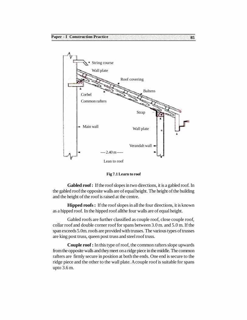
85Paper - I Construction Practice
Fig 7.1 Learn to roof
Gabled roof : If the roof slopes in two directions, it is a gabled roof. Inthe gabled roof the opposite walls are of equal height. The height of the buildingand the height of the roof is raised at the centre.
Hipped roofs : If the roof slopes in all the four directions, it is knownas a hipped roof. In the hipped roof allthe four walls are of equal height.
Gabled roofs are further classified as couple roof, close couple roof,collar roof and double corner roof for spans between 3.0 m. and 5.0 m. If thespan exceeds 5.0m. roofs are provided with trusses. The various types of trussesare king post truss, queen post truss and steel roof truss.
Couple roof : In this type of roof, the common rafters slope upwardsfrom the opposite walls and they meet on a ridge piece in the middle. The commonrafters are firmly secure in position at both the ends. One end is secure to theridge piece and the other to the wall plate. A couple roof is suitable for spansupto 3.6 m.
String course
Wall plate
Roof covering
BaltensCorbelCommon rafters
Main wall
Strap
Wall plate
Verandah wall---- 2.40 m -----
Lean to roof
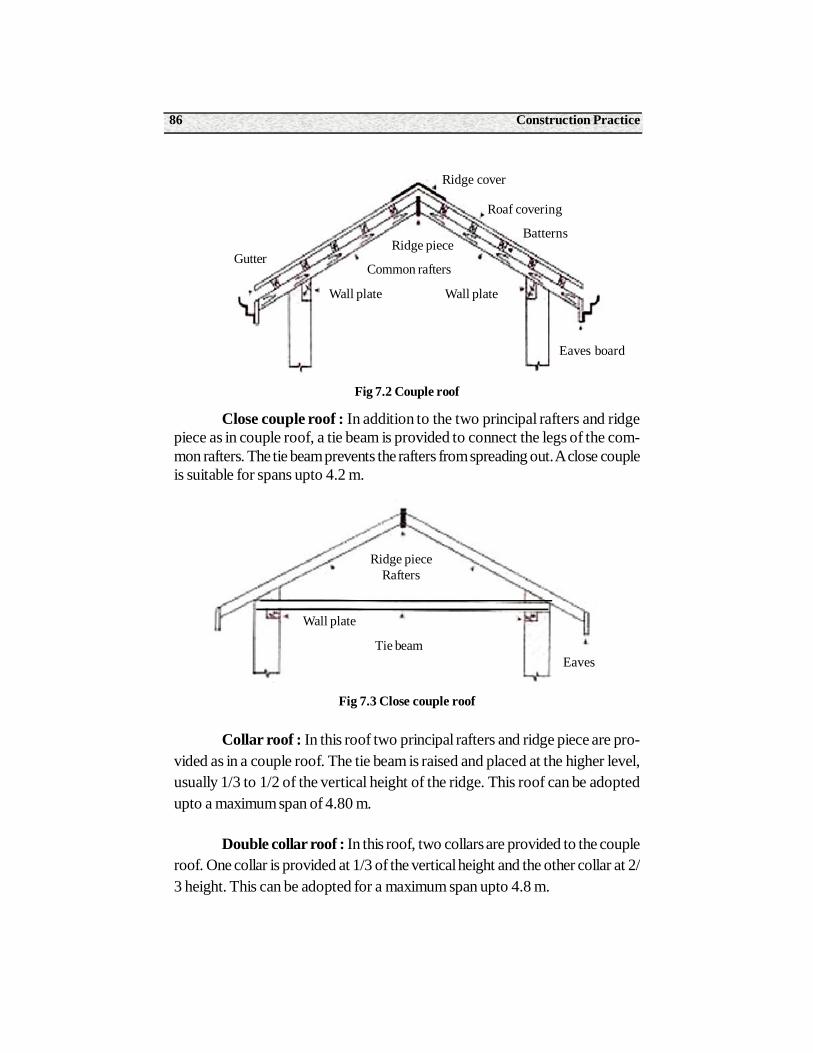
Construction Practice86
Fig 7.2 Couple roof
Close couple roof : In addition to the two principal rafters and ridgepiece as in couple roof, a tie beam is provided to connect the legs of the com-mon rafters. The tie beam prevents the rafters from spreading out. A close coupleis suitable for spans upto 4.2 m.
Fig 7.3 Close couple roof
Collar roof : In this roof two principal rafters and ridge piece are pro-vided as in a couple roof. The tie beam is raised and placed at the higher level,usually 1/3 to 1/2 of the vertical height of the ridge. This roof can be adoptedupto a maximum span of 4.80 m.
Double collar roof : In this roof, two collars are provided to the coupleroof. One collar is provided at 1/3 of the vertical height and the other collar at 2/3 height. This can be adopted for a maximum span upto 4.8 m.
Ridge cover
Gutter
Roaf covering
BatternsRidge piece
Common rafters
Wall plate
Eaves board
Wall plate
Ridge pieceRafters
Wall plate
Tie beamEaves
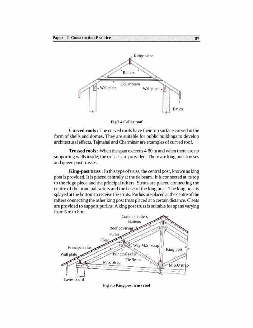
87Paper - I Construction Practice
Fig 7.4 Collar roof
Curved roofs : The curved roofs have their top surface curved in theform of shells and domes. They are suitable for public buildings to developarchitectural effects. Tajmahal and Charminar are examples of curved roof.
Trussed roofs : When the span exceeds 4.80 m and when there are nosupporting walls inside, the trusses are provided. There are king post trussesand queen post trusses.
King-post truss : In this type of truss, the central post, known as kingpost is provided. It is placed centrally at the tie beam. It is connected at its topto the ridge piece and the principal rafters .Struts are placed connecting thecentre of the principal rafters and the base of the king post. The king post issplayed at the bottom to receive the struts. Purlins are placed at the centre of therafters connecting the other king post truss placed at a certain distance. Cleatsare provided to support purlins. A king post truss is suitable for spans varyingfrom 5 m to 8m.
Fig 7.5 King post truss roof
Collar beamWall plate
Eaves
Wall plate
Ridge piece
Rafters
Common raftersBattens
Roof coveringPurlin
Cleat
Principal rafter
Wall plate
M.S.U strap
King postWay M.S. Strap
Principal rafterTie BeamM.S. Strap
Eaves board
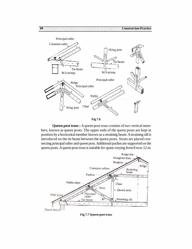
Construction Practice88
Fig 7.6
Queen post truss : A queen post truss consists of two vertical mem-bers, known as queen posts. The upper ends of the queen posts are kept inposition by a horizontal member known as a straining beam. A straining sill isintroduced on the tie beam between the queen posts. Struts are placed con-necting principal rafter and queen post. Additional purlins are supported on thequeen posts. A queen post truss is suitable for spans varying from 8 m to 12 m.
Fig 7.7 Queen post truss
Principal rafter
Common rafter
Tie beamM.S strimp
Ridge
King post
Principal rafter
Clear
Putlin
Principal rafter
M.S strimp
King post
Tie beam
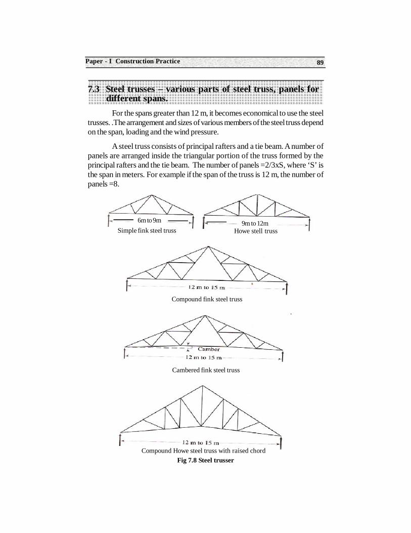
89Paper - I Construction Practice
7.3 Steel trusses – various parts of steel truss, panels for different spans.
For the spans greater than 12 m, it becomes economical to use the steeltrusses. .The arrangement and sizes of various members of the steel truss dependon the span, loading and the wind pressure.
A steel truss consists of principal rafters and a tie beam. A number ofpanels are arranged inside the triangular portion of the truss formed by theprincipal rafters and the tie beam. The number of panels =2/3xS, where ‘S’ isthe span in meters. For example if the span of the truss is 12 m, the number ofpanels =8.
Fig 7.8 Steel trusser
6m to 9m 9m to 12mSimple fink steel truss Howe stell truss
Compound fink steel truss
Cambered fink steel truss
Compound Howe steel truss with raised chord
Construction Practice90
The panels are arranged by providing supporting members in the truss.Depending upon the number of panels, the arrangement of the members change.For spans varying between 6m to 9 m, simple fink steel truss is provided. Howesteel truss is provided for spans varying from 9m to 12 m. Compound fink steeltruss, cambered fink steel truss and compound howe steel truss is provided forspans between 12 m to 15m.Arch steel truss is provided for spans between 15m and 20 m, while bow –string steel truss is provided for spans between 20 mto 30m. To admit light into the rooms North light steel truss is provided. In shedsof large areas north light trusses are provided.
7.4 Roof covering material for pitched roofs, flat roof and R.C.C. roof
The following factors should be considered before selecting the type ofroof covering for a pitched roof.
1. Climate of the locality.
2. Nature of the building.
3. Initial cost and maintenance cost.
4. Durability.
5. Availability of material.
6. Fabrication facilities.
7. Type of roof framework.
8. Resistance to fire and heat
9. Special features of the locality.
The following are the various types of roof coverings which are commonlyused for the pitched roofs.
1. Thatch : This is a very light roof covering. It is combustible. It absorbsmoisture rapidly abd is easily liable to decay. It is unstable against high winds. Abed of matting is provided to receive the thatch. The pitch of this room is 45degrees. It is the cheapest form of roof and is very simple in construction. Thatchroof is used mostly in rural areas.
2. Ordinary half-round country tiles : These are used for cheapbuildings. If these tiles are laid in two layers, the roof is known as a double-tiledroof. An overlap of at least 80 mm should be provided when these tiles areused. These tiles are liable to break easily. They require frequent replacement.
91Paper - I Construction Practice
3. Shingles : The roof is covered with shingles made from well seasonedtimber. The length of the shingle ranges from 300 mm to 380 mm, while its widthrange from 60 mm to 250 mm. This covering is useful in hilly areas where thewood is available easily and cheaply.
4. Patent tiles : This is a tiled roof, where patent tiles like Mangaloretiles, Allahabad tiles etc are used. These are the premium tiles having characteristiccolor. These tiles are more durable and they don’t require frequent replacement.
5. Trafford asbestos-cement tiles : These are made of cement andasbestos. They possess less corrugations and are laid with laps of 150 mm and100 mm at the ends and sides respectively.
6. Eternit slates : Slates are stone slabs of area 0.125 m2. These arefire-resisting, light and cool. They are not easily affected by weather. The eternityslates are available in three colors-grey, black and red.
7. Corrugated galvanized iron sheets : The galvanized iron sheetsare prepared by pressing flat wrought-iron plates between rollers with groovesor teeth and then they are galvanized with a coat of zinc. These sheets arecommonly called as G.I. sheets. The corrugations help to increase strength, rigidityand they permit easy flow of rain water. These are available in lengths of 1.2 mto 3.6 m, and in widths ranging from600 mm to 900 mm, the thickness variesfrom 0.18 mm to 1.60 mm. They are costly and do not offer resistance to fireand sound.
8. Asbestos cement corrugated sheets : The cement is mixed withabout 15 percent of asbestos fibres and the paste so formed is pressed underrollers with grooves or teeth. These sheets are called A.C. sheets. The corrugatedA.C. sheets are used for factories, workshops, garages, big halls etc. They arecheap, fire resisting, light in weight, strong, tough, sound proof, impervious anddurable.
Roof covering material for flat roof : The various types of flat roofsare Madras terraced roof, Bengal terraced roof and R.C.C. roof. In madrasterraced roof teak wod joists are placed on rolled steel joists with a furringpiece between them.
A course of specially prepared terraced bricks is laid diagonally acrossthe joists. After the brick course has set, a course of brick bat concrete is laid.The concrete is well rammed for three days and allowed to set. The flat tiles arethen laid over the layer of concrete.
In Bengal terraced roof, the rafters are placed at slight inclination. Thebattens are placed at right angles to the rafters. A course of flat tiles is then laid
Construction Practice92
in mortar over the battens. A layer of tiles or concrete is then laid over this layerand two or three coats of plaster is then laid over it.
In RCC roof, a formwork is prepared and steel reinforcement is placedover it with sufficient cover for reinforcement. Plain cement concrete with cement,fine aggregate and coarse aggregate is prepared and it is thoroughly mixed byadding water. This plain cement concrete is poured over this steel reinforcement.It is cured for a period of 21 days.
7.5 Tools required to fix AC sheet, G.I. sheet and roof covering
The following are the tools required to fix AC sheet, GI sheet and Roofcovering.
• A steel tape is required to mark the length of the sheets, Overlap length of the sheets and purlin spacing.
• A plane saw is required for cutting the sheets and a tenon saw is required to cut the sheets and place them without gaps.
• A drilling machine is required to drill holes in the sheets. Wolf drilling machine or a hand drilling machine may also be used.
• As the diameter of the hole is greater than the diameter of the screw, a GI washer and a bitumen washer shall be provided.
• A screw driver and a cutting plier are required to tighten the nuts or bolts of a screw.
7.6 Methods for fixing of AC sheetThe following points should be observed in connection with the fixing of
AC sheets.
1. The sheets should be laid with smooth edge upward and the end marked top pointing towards the edge.
2. The sheets are usually laid with an end lap of 150 mm.
3. The purlin spacing and length of sheets should be properly checked before the process of laying starts.
4. The holes for fixing the accessories must be drilled. The diameter ofthe hole should be 3 mm greater than the diameter of the screw or bolt to beused. A bitumen washer must be provided under the GI flat washer with eachbolt or screw.
93Paper - I Construction Practice
5. The sheets should be properly mitred or cut to avoid gaps where four sheets meet at lap.
6. The nuts of screws or bolts should be moderately tightened when 10 to 12 sheets have been laid. The screws or bolts on the purlin should not be tightened too much.
7. The ridge capping should preferably be secured to the ridge purlin by the same kind of bolts which are used for fixing the sheets.
8. The unsupported length of overhang at the eaves of the sheets should not exceed 300 mm.
7.7 General requirements of roofThe following are the requirements of a good and well planned roof.
1. It should be durable against the adverse effects of various agencies such as wind , rain and snow.
2. It should have sufficient insulation against sound and heat.
3. It should be stable and it should be capable of taking the loads likely to come over it.
4. It should be well drained.
5. It should have efficient water-proofing arrangement.
6. It should be fire resistant.
7.8 Weather proof course on RCC roof All the flat roof at present are constructed of RCC. To make the roof
water proof or weather proof the following methods are employed.
1. Finishing : For ordinary buildings of cheap construction, the finishingis done at the time of laying cement concrete. The finishing of flat roof is carriedin cement mortar of proportion 1:4.
2. Bedding concrete and flooring : In this method, the surface of theR.C.C. slab is kept rough and on this surface, a layer of concrete is laid. Theconcrete may be mass concrete 1:5:10 of 100 mm thickness or concrete ofproportion 1:2:4 of 50 mm thickness known as bedding concrete. Over thissurface flooring of Indian patent stone, tiles, or terrazzo is laid.
3. Mastic asphalt and jute cloth : In this method, a layer of hotmastic asphalt is laid on the roof surface. The jute cloth is spread over this layer.Then one more layer of mastic asphalt is applied so that the jute is sand witched
Construction Practice94
between the two layers of mastic asphalt. The sand is sprinkled over the entiresurface of the roof. For better grip, the lead sheets are inserted at the junction ofparapet wall and roof.
4. Use of water-proofing compounds : Some water proof compoundslike Pudlo, Impermo, etc., are added to the cement during construction. Thesewater-proofing compounds prevent seepage, leakage and damp caused by thecapillary absorption of the moisture in cement, mortar and concrete. Usually 10N of such compound is added to a bag of cement. If the compound is in fluidshape, one litre of that compound is added to a bag of cement.
SummaryClassification of Roofs : The roofs are classified as flat roofs, sloping
roofs and curved roofs.
Types of flat roofs : The various types of flat roofs are Madras terracedroof, Bengal terraced roof and Reinforced cement concrete roof.
Types of sloping roofs : Lean to roof, Gabled roof and hipped roof. Alean to roof slopes in one direction only, gabled roof in two directions and hippedroof in all the four directions.
Roof trusses for a span of 3 m to 5 m are couple roof truss, closecouple roof truss, collar roof truss and double collar roof truss. For spans of 5mto 8 m, king post truss is used. For spans between 8 m and 12 m queen posttrusses are used. For spans greater than 12 m steel roof trusses are used.
Roof covering materials for pitched roof : The various materials forpitched roof are thatch, half round country tiles, shingles, patent tiles, Traffordasbestos-cement tiles, eternity slates, corrugated galvanized iron sheets andasbestos cement corrugated sheets.
Methods of weather proof course on RCC roofs are finishing, beddingconcrete and flooring, mastic asphalt and jute cloth and water proofingcompounds.
Short Answer Type Questions1. Define roof.
2. List out the classification of roofs.
3. What are the various types of pitched roofs.?
4. What are the various types of flat roofs ?
5. Define gable roof and hipped roof.
95Paper - I Construction Practice
6. List out the various types of roof trusses.
7. Mention the various types of materials used for pitched roof covering.
8. List out the various tools required for fixing AC sheet GI sheet and roof covering.
9. What are the various types of steel roof trusses.?
10. What are the various methods of applying weather proof course on RCC roof ?
11. Where do you provide queen post truss?
12. Where do you provide a king post truss?
13. What are the factors to be considered while selecting material for a roof ?
Long Answer Type Questions1. What are the various types of pitched roofs.?
2. Draw a neat sketch of a king post truss and mention any six parts.
3. Draw a neat sketch of a queen post truss and indicate any six parts.
4. Where do you provide steel roof truss? Draw a neat sketch of a steel roof truss. Mention the various types of steel roof trusses.
5. Describe the roof coverings which are commonly used for pitched roofs.
6. Describe the roof coverings which are commonly used for flat roofs.
7. What is the procedure adopted for fixing AC sheet, GI sheet roof covering ?
8. What are the methods adopted for water-proofing of RCC roof?
OJT Questions
1. Calculate the material required for various types of trusses.
2. Calculate the weight of steel reinforcement in RCC slab by measurement of lengths of the steel rods and counting them.
Construction Technology96
Structure8.0 Introduction
8.1 Technical terms involved in stairs and staircases
8.2 Characteristics of a good stair
8.3 Various types of stairs- Straight, Quarter turn, half turn, doglegged, open well, Bifurcated and spiral stairs
Learning ObjectivesAfter completion of this unit the student shall be able to understand the following
• Technical terms in stairs.
• Characteristics of a good stair
• Various types of stairs
8.0 Introduction
A stair is provided to afford the means of ascent and descent. Due torestriction of landed area, we are forced to go in for high rise buildings. Study ofdifferent types of stairs and its appropriate locations is absolutely necessary.Further innovations such as ramps, lifts, elevators are replacing stairs, but stillstairs are most widely used.
8UNIT
Stairs And Staircases
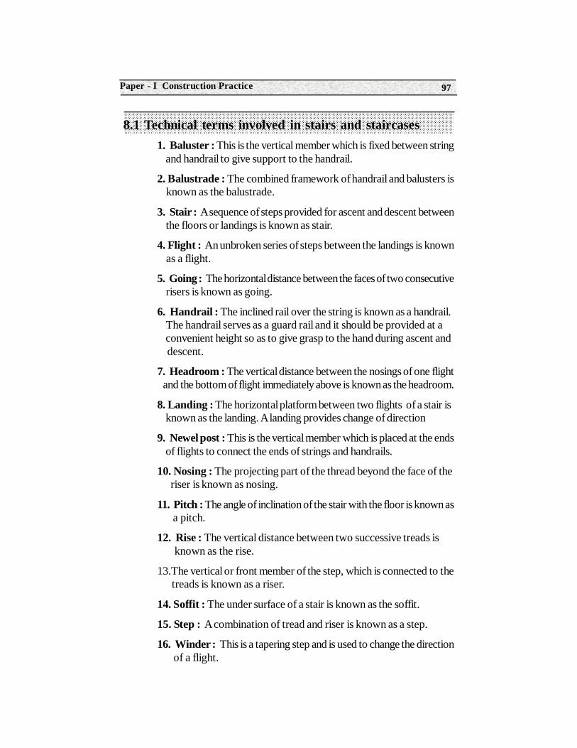
97Paper - I Construction Practice
8.1 Technical terms involved in stairs and staircases1. Baluster : This is the vertical member which is fixed between string and handrail to give support to the handrail.
2. Balustrade : The combined framework of handrail and balusters is known as the balustrade.
3. Stair : A sequence of steps provided for ascent and descent between the floors or landings is known as stair.
4. Flight : An unbroken series of steps between the landings is known as a flight.
5. Going : The horizontal distance between the faces of two consecutive risers is known as going.
6. Handrail : The inclined rail over the string is known as a handrail. The handrail serves as a guard rail and it should be provided at a convenient height so as to give grasp to the hand during ascent and descent.
7. Headroom : The vertical distance between the nosings of one flight and the bottom of flight immediately above is known as the headroom.
8. Landing : The horizontal platform between two flights of a stair is known as the landing. A landing provides change of direction
9. Newel post : This is the vertical member which is placed at the ends of flights to connect the ends of strings and handrails.
10. Nosing : The projecting part of the thread beyond the face of the riser is known as nosing.
11. Pitch : The angle of inclination of the stair with the floor is known as a pitch.
12. Rise : The vertical distance between two successive treads is known as the rise.
13.The vertical or front member of the step, which is connected to the treads is known as a riser.
14. Soffit : The under surface of a stair is known as the soffit.
15. Step : A combination of tread and riser is known as a step.
16. Winder : This is a tapering step and is used to change the direction of a flight.
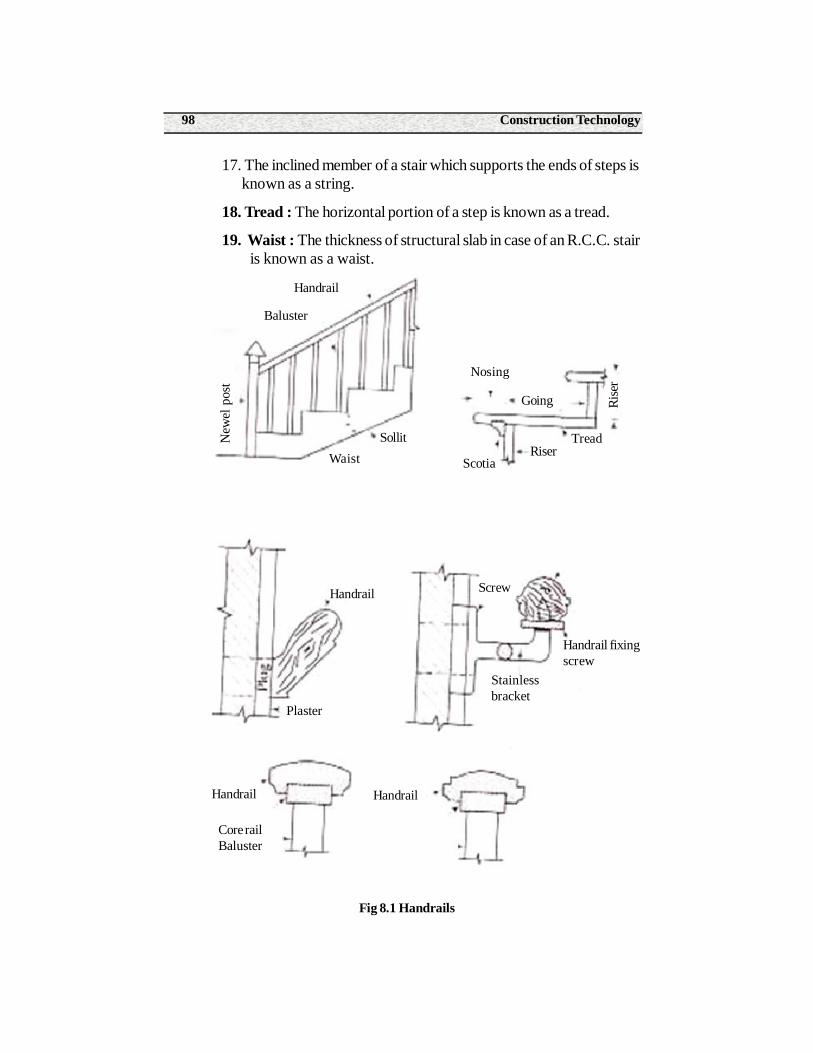
Construction Technology98
17. The inclined member of a stair which supports the ends of steps is known as a string.
18. Tread : The horizontal portion of a step is known as a tread.
19. Waist : The thickness of structural slab in case of an R.C.C. stair is known as a waist.
Fig 8.1 Handrails
Baluster
New
el p
ost
Handrail
Waist
Nosing
Handrail
Sollit
Plaster
Core railBaluster
HandrailHandrail
Going
RiserScotia
Tread
Screw
Handrail fixingscrew
Stainlessbracket
Rise
r
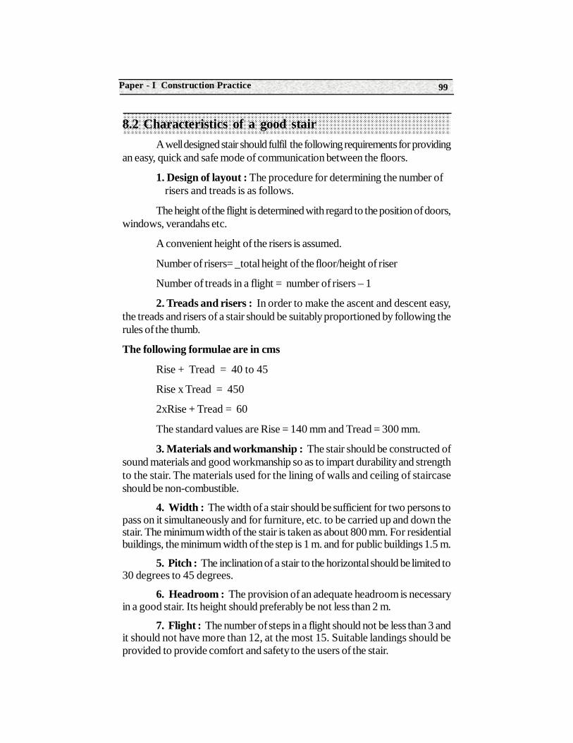
99Paper - I Construction Practice
8.2 Characteristics of a good stairA well designed stair should fulfil the following requirements for providing
an easy, quick and safe mode of communication between the floors.
1. Design of layout : The procedure for determining the number of risers and treads is as follows.
The height of the flight is determined with regard to the position of doors,windows, verandahs etc.
A convenient height of the risers is assumed.
Number of risers= _total height of the floor/height of riser
Number of treads in a flight = number of risers – 1
2. Treads and risers : In order to make the ascent and descent easy,the treads and risers of a stair should be suitably proportioned by following therules of the thumb.
The following formulae are in cms
Rise + Tread = 40 to 45
Rise x Tread = 450
2xRise + Tread = 60
The standard values are Rise = 140 mm and Tread = 300 mm.
3. Materials and workmanship : The stair should be constructed ofsound materials and good workmanship so as to impart durability and strengthto the stair. The materials used for the lining of walls and ceiling of staircaseshould be non-combustible.
4. Width : The width of a stair should be sufficient for two persons topass on it simultaneously and for furniture, etc. to be carried up and down thestair. The minimum width of the stair is taken as about 800 mm. For residentialbuildings, the minimum width of the step is 1 m. and for public buildings 1.5 m.
5. Pitch : The inclination of a stair to the horizontal should be limited to30 degrees to 45 degrees.
6. Headroom : The provision of an adequate headroom is necessaryin a good stair. Its height should preferably be not less than 2 m.
7. Flight : The number of steps in a flight should not be less than 3 andit should not have more than 12, at the most 15. Suitable landings should beprovided to provide comfort and safety to the users of the stair.
Construction Technology100
8. Winders : If winders are unavoidable, they should be placed at thebottom rather than the top of the flight.
9. Handrail : When a flight consists of more than three steps, a handrailshould be provided at least on one side. The height of the handrail should beapproximately 800 mm.
10. Location : The stairs should be so located that they are well-lighted and ventilated. They should have convenient and spacious approaches.In case of public buildings the stairs should be located near the main entrance. Incase of private buildings, the stair should be centrally located so as to have easyaccess from all rooms.
8.3 Various types of stairs- Straight, Quarter turn, half turn, doglegged, open well, Bifurcated and spiral stairsThe following are the various types of stairs
1. Straight stairs
2. Quarter- turn stairs
3. Bifurcated stairs
4. Half-turn stairs
5. Dog-legged stairs
6. Open well stairs
7. Three-quarter-turn stairs
8. Spiral stairs
1. Straight stairs : In case of straight stairs, all steps lead in onedirection only. This type of stairs may consist of one or more flights. When thespace available for staircase is long but narrow in width.
Fig 8.2 Straight stairs
2. Quarter-turn stairs : A stair turning through one right angle is knownas a quarter-turn stairs. It consists of one flight, landing and the second flight atone right angle to the first flight.
101Paper - I Construction Practice
Fig 8.3 Quarter turn stairs
3.Bifurcated stairs : If a quarter-turn stairs is branched into two flightsat a landing, it is known as a bifurcated stair. This type of stair is commonly usedin the public buildings near their entrance hall. The stair has a wider flight at thebottom which bifurcates into two narrower flights at the landing- one turning tothe left and the other to the right.
Fig 8.4 Bifurcated stairs
4. Half-turn stairs : A stair turning through two right angles is knownas a half-turn stair. It consists of one straight flight, landing and the other flightstarting from the landing in the opposite direction.
Fig 8.5 Half turn stairs
Dog legged stair Open pewel stairs
Landing
Winder Landing
Ope
n re
ctan
gula
r wel
l
Ope
n ge
omet
rical
wel
l
Construction Technology102
5. Dog-legged stair : It is a half turn stairs in which two flights run inopposite directions and there is no space between them in plan. When the totalwidth available for stairs is equal to two times the width of the steps, this type ofstairs are useful. Its name is derived from the shape of its sectional elevation.
6. Open well stairs : It is a half turn stair , in which there is a wellshape or opening between the two parallel flights in the plan. Its name is derivedfrom its sectional elevation. These stairs are useful where available space for astair case has a width greater than twice the width of steps.
7. Three-quarter turn stairs : A stair turning through three right anglesis known as a three-quarter turn stair. It should have two landings. In this casean open well is formed.
Fig 8.6 Three quarter turn stairs
8. Spiral stairs : In this type of stair, the steps radiate from the centreand they do not have either any landing or any intermediate newel post. Theflight consists of winders only and they may be continued through any number ofturns. The spiral stairs are useful when the space available is limited and thetraffic is less.
Fig 8.7 Spiral stairs
Landing
103Paper - I Construction Practice
Summary• A well designed stair should fulfil the following requirements
• The rise and tread selected should satisfy the following thumb rules
• Rise + Tread =40 to 45. Rise x tread =410 to 450. 2 x Rise + Tread = 60
• The stairs should be constructed of sound and non combustible materials.
• The minimum width of the stair should not be less than 800 mm.
• The inclination of the stair to the horizontal should be limited to30 to 45 degrees.
• The height of the headroom should not be less than 2m.
• The minimum number of steps in a flight is 3 and the maximum number is 15.
• As far as possible, the winders should be avoided .Handrail should be provided at least on one side.
Short Answer Type Questions1. Define the following : Stair, Flight, Landing, Rise, Tread, Riser, Pitch, Winder, Baluster.
2. Where do you provide a winder?
3. What should be the height of the hand rail?
4. What should be the minimum and maximum number of steps in a flight.
5. What should be the minimum width of the step?
6. List out the various types of stairs.
7. Mention any two types of half –turn stairs.
Long Answer Type Questions1. What are the characteristics of a good stair?
2. What are the various types of stairs.? Describe any two stairs.
3. Explain dog legged stair case with a neat sketch.
4. Explain open well stair case with a neat sketch.
Construction Technology104
Structure9.1 Definition of form work and objectives
9.2 Requirements of From work
9.3 Material used for form work
9.4 Removal of form work
9.5 Form work for column, column footing
9.6 Failure of form work
Learning ObjectivesAfter studying this unit the student should be able to understand about
• Form work for column and column footing
• Material used
• Removal of form work
• Failure of form work
9.1 Definition of form work and objectives The temporary structure erected to support the concrete in required
shape till it hardens and becomes self-supporting is known as form work. Thisalso called as centering or shuttering.
9UNIT
Form Work
105Paper - I Construction Practice
9.1.2 Objectives of form work
(i) To provide a temporary supporting structure to fresh concrete in required shape.
(ii) To provide a smooth surface.
(iii) To take self weight of concrete and the impact due to vibration of concrete.
(iv) To place the reinforcement in position and to enable the worker for tieing the reinforcing rods as per design including cement mortar cover blocks.
9.2 Requirements of Form work(i) The material for form work should be easily available, reasonable cost and suitable for reuse.
(ii) The forms must be strong enough to bear the loads of concrete and workmen, the liquid pressure of fresh concrete and the impact of ramming or vibrating.
(iii) The forms must be water-proof so as to prevent the absorption of water from the concrete.
(iv) The forms must be stiff enough to have minimum deflection.
(v) The forms should be capable of providing rigid join to prevent bulging or twisting and flow of liquid concrete.
(vi) All surface of form work should be plane to reduce the cost of surface finishing.
(vii) Forms should be capable of gradual and easy removal the completely or partially.
9.3 Material used for form workThe usual materials which are employed in the preparation of form work
are steel and timber. The form work is also sometimes prepared from aluminium,pre-cast concrete on fibre glass for cast-in-situ members involving curvedsurfaces.
1. Steel form work : The steel is used for, work when it is desire to re-use the form work several times. The initial cost of steel work is very high. Butit proves to be economical for large requiring many repetitions of the form work.The erection and removal of steel formwork are simple and it presents a smoothsurface on removal.
Construction Technology106
Following are the Advantages of steel form work over timber formwork
(i) It can be re-used several times nearly more than timber formwork.
(ii) It does not absorb water from the concrete and hence, the chances of the formation of honey-combed surface and brought down to the minimum level.
(iii) It does not shrink or distort and hence it is possible to achieve higher degree of accuracy and workmanship by its use as compared to the timber formwork.
(iv) It is easy to install and dismantle and hence, there is saving in the labour cost.
(v) It gives excellent exposed concrete surfaces requiring no further finishing treatment. The surface obtained by the use of timber formwork invariably requires plastering for getting the desired finish of the concrete surface.
(vi) It process more length and is more durable than the timber formwork.
(vii) The design calculation for the steel form work system can be made precisely because of the known characteristic of steel.
2. Timber : when formwork is required for small works requiring lessrepetitions the timber is preferred to steel. The timber formwork is cheap ininitial cost and it can be easily adopted or altered for a new use. The timber tobe used as formwork should be well-seasoned free from loose knots, light inweight and easily workable with nails without splitting.
Following facts in connection with the timber formwork should beremembered
(i) The timber is to receive wet concrete. Hence the timber formworkshould be neither too dry nor too wet. If it is too dry, the timber will swell andget distorted than wet concrete is placed on it. This will affect the workability ofconcrete and honeycomb surfaced will appear on removals of the formwork.On the other hand if it is too wet, the timber will shrink in hot weather resultingin gaps in the formwork through which concrete will flow out. Hence, the ridgeswill be formed on the concrete surface It is found that a moisture content ofabout 20 % is appropriate for the timber formwork.
(ii) The dimension of components of the timber formwork will dependupon the loads to be carried and the availability of timber section. But generally,the latter is the governing factor as the former can be adjusted by suitable spacingof the supports.
107Paper - I Construction Practice
(iii) The minimum nails should be used in timber formwork and the nailheads should be kept projecting so as to facilitate easy removal.
(iv) The timber formwork proves to be economical for building withminimum number of vibrations in the dimension of the rooms. Thus, the cuttingof timber pieces is brought down to the minimum.
(v) It is the common practice to sport formwork for slab in building withthe timber bellies which are cut to approximate size with wedges below them tofinal adjustment. It leads to the formation of weak points which are seldomprevented from displacement. The timber ballies are generally not straight andthey do not transmit the load axially.
The idea of using plywood as the formwork is becoming popular atpresent became it affords the following advantages over the timber formwork.
(i) The plywood formwork can be re-used several times as comparedto ordinary timber formwork. Under normal conditions the plywood formworkcan be used for 20 times to 25 times and the timber formwork can be used for10 times top 12 times.
(ii) The plywood formwork gives surface which are plain and smoothand hence they may not require any further finishing treatment.
(iii) It is possible to cover up more idea by using large size panel andhence, there is considerable reduction in the labour cost of fixing and dismantlingof formwork.
9.4 Removal of form workThe operation of removing the formwork is commonly known as the
stripping. The forms which can be conveniently re-used are known as the panelforms. The forms which cannot be re-used because of tier non-standard orwhich are meant for structures which do not require stripping are known as thestationary forms.
The formwork is removed only when the concerto has become sufficientlyhard sop that removal of formwork will not damage the structure. The length oftime for which formwork should be kept in position depends on the followingfactors:
(i) Amount and nature of dead load,
(ii) Character and quality of concrete
(iii) Shape, span and situation of structure and
(iv) Temperature of the atmosphere.
Construction Technology108
In general it may be mentioned that the formwork which Is merely toretain the concrete can be removed with in 2 or 3 days as in case sides of aconcrete beam. But when the formwork is required to carry the whole weight ofconcrete it becomes necessary to keep the form work in position for a longerperiod. Thus the formwork in case of floors and bottoms of beams is to beremoved at least after 10 days and 21 days respectively. For slabs and beamsprojecting in the form of cantilevers, the formwork should only be removedafter making construction of the necessary counter weight to balance thecantilever action. In general, it may be stated that the formwork should be keptas long as possible because it would assists the curing.
The quality of cement used in the preparation of concrete also greatlyaffects the period for which the formwork is to be kept in position. When rapidhardening cement is used the formwork can be removed after 3 to 4 days and incase of high alumina cement, this period is reduced to few hours only.
9.5 Form work for column, column footing9.5.1 Formwork for Column footings
Depending upon the shape of the column footing, the formwork of suitableshape is to be provided to receive the concrete. The usual shape is square orrectangular and it is accompanied by vertical sides or steps or sloping sides.
Fig 9-1 shows a column footing with vertical sides. A box of requireddimension is prepared from plank and one side of the box is made about 300mm longer than the other. Suitable braces are provided to make the box rigidand strong.
Fig. 9.1 Column footing with vertical sides
Braces
Plan
Elevation Planks
109Paper - I Construction Practice
For further security the opposite sides may be connected by wore fixedon nails before concrete is placed in the formwork. The wire will return in theconcrete when formwork is removed.
Fig 9-2 Shows a column footing with steps. It is just similar to above.The bottom box is fitted with concrete and after box is filled with concrete andafter a short time, the top box is placed on the surface of the wet concrete.
Fig. 9.2 Column footing with steps Fig. 9.3 Column footing with sloping sides
Fig. 9.3 Shows a column footing with the sloping sides. The bottomplanks are of required vertical sides and after placing footing reinforcement, thebox for side planks is placed on the bottom planks and both are suitablyconnected. Sometimes the concrete is placed up to the top of bottom planks isbefore the box of side planks is placed in position.
The column formwork consists of box prepared from four separatesides. The four of the box are held in position by wooden blocks, bolts andyokes. Fig 9.4 shows the details of formwork for an R.C.C. column of section300 mm x 300 mm. The important features of the formwork for R.C.C. columnsare.
(i) The formwork should be designed to resist the high pressure resultingfrom the quick filling of the concrete.
Top Box
ElevationBottom planks
Braces Side plaks
Plan
Planks
Elevation
Plan
Construction Technology110
(iii) The spacing of yokes is about one meter, But it should be carefullydetermined by working oat the greatest length of the formwork which can safelyresist the local coming on the form work.
(iii) Depending upon the shape of the column the box can be suitablyprepared.
(iv) A hole is generally provided at the bottom of the form work ofcolumn to remove the debris which might have fallen before placed. This holetermed as the cleanout hole or washout hole filled up before placing of theconcrete starts.
Fig 9.4 Formwork for column
(v) A wash of water is given to the inside of the formwork just beforestart the laying concrete.
(vi) The boxes should be designed in such a way that with little alteration,the can be re-use 3d for column with smaller cross-section on upper floors.
(vii) In order to make the dislocation of boxes easy, the nails are keptprojecting instead of being firmly driven. Thus they can remove easy by the clawhammer.
(viii) The wooden yokes being efficient and cheap are widely used. Butthey can be replaced by the metal, clamps of suitable design.
Yoke
25 mm thick planks
350 mm
Elevation
1.00 m
m
Planks
Yoke 40 mm x 40 mm
Wooden blocks40 mm x 40 mm x 40 mm12 mm Dia. Bolts
Plan
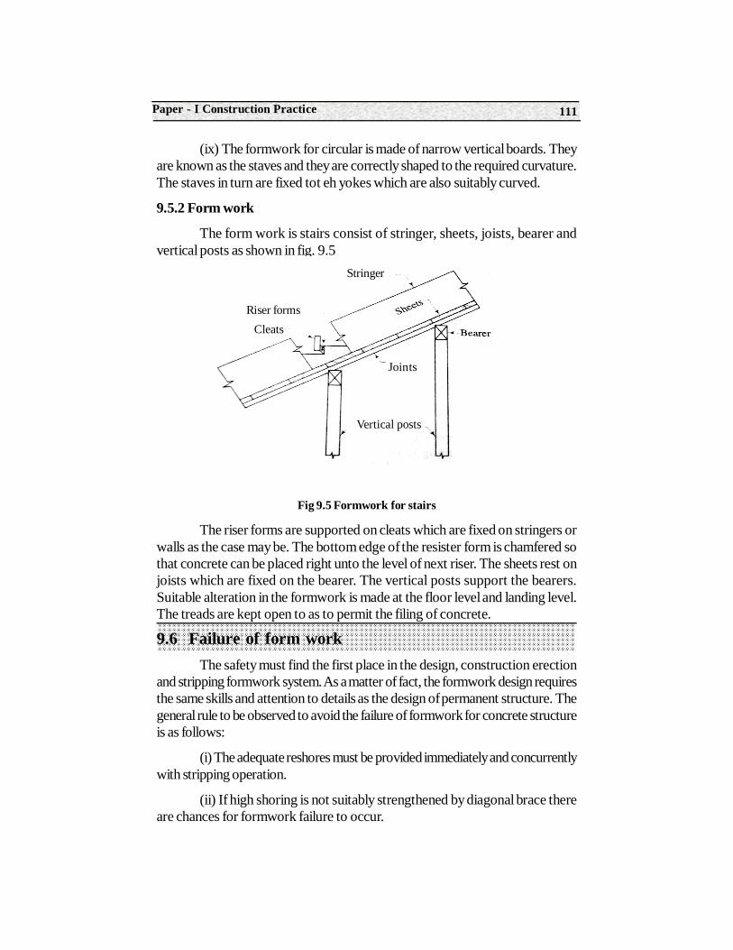
111Paper - I Construction Practice
(ix) The formwork for circular is made of narrow vertical boards. Theyare known as the staves and they are correctly shaped to the required curvature.The staves in turn are fixed tot eh yokes which are also suitably curved.
9.5.2 Form work
The form work is stairs consist of stringer, sheets, joists, bearer andvertical posts as shown in fig. 9.5
Fig 9.5 Formwork for stairs
The riser forms are supported on cleats which are fixed on stringers orwalls as the case may be. The bottom edge of the resister form is chamfered sothat concrete can be placed right unto the level of next riser. The sheets rest onjoists which are fixed on the bearer. The vertical posts support the bearers.Suitable alteration in the formwork is made at the floor level and landing level.The treads are kept open to as to permit the filing of concrete.
9.6 Failure of form workThe safety must find the first place in the design, construction erection
and stripping formwork system. As a matter of fact, the formwork design requiresthe same skills and attention to details as the design of permanent structure. Thegeneral rule to be observed to avoid the failure of formwork for concrete structureis as follows:
(i) The adequate reshores must be provided immediately and concurrentlywith stripping operation.
(ii) If high shoring is not suitably strengthened by diagonal brace thereare chances for formwork failure to occur.
Stringer
Riser formsCleats
Joints
Vertical posts
Construction Technology112
(iii) It should be remembered that the form are continuously supportedstructure and as such, they must be provided with uniform bearing at each support.
(iv) The entire work should be carried out under the strict and directsupervision of skilled persons or engineers only.
(v) The design form work should provide for possible shocks andvibrations.
(vi) The details which are difficult to perform should be avoided as inmany cases, such details will not be satisfactorily performed and may becomethe starting point for causing a formwork failure.
(vii) The stripping of form and reshoring shoring not be carried out inunbalanced way. It will otherwise lead to unnecessary stresses in freshly laidconcrete.
(viii) The wedging of post of counter-balance load compression mustbe carried out the extreme care so that the assembled form support remainsundisturbed.
9.6.1 Maintenance of Formwork
The form after being removed from position should be carefully cleanedand stored . The maintenance of formwork is essential to re-use it several timesand thus it leads to overall economy of formwork. The damaged components offormwork should be repaired and the store of formwork should be located atsuch place that there are minimum chances for wind, moisture etc. to have adverseeffects on it.
Summary• When concrete is placed it is in a plastic state. It requires to be supported by a temporary supports this temporary support is known as the formwork.
• Form work should provide a smooth surface.
• The material used for formwork should be easily available.
• The form works must be water proof
• All surface of formwork should be plane to reduce the cast of surface finishing .
• Forms should be capable of gradual and easy removal either completely or partially.
113Paper - I Construction Practice
Short Answer Type Questions1. Define Formwork .
2. What are the requirement of formwork ?
3. Write the objectives of formwork.
Long Answer Type Questions 1. Describe the material used for preparing formwork.
2. Explain with a neat sketch the form work used for column.
3. What are the advantages of steel formwork over timber formwork.
4. Explain the arrangement of formwork for a stairs.
5. Write short note on removal of formwork .
6. Explain about failure of formwork.
On The Job Training
1. The student should visit the sites of different centering works of columns foundations and slab.
2. Record the types of formworks.
Construction Technology114
Structure10.1 Definition of scaffolding
10.2 Types of scaffolding
10.3 Shoring and underpinning
Learning ObjectivesAfter studying this unit the student should be able to understand
• Scaffolding
• Types of scaffolding
• Shoring and under pinning
10.1 Definition of scaffoldingDefinition : When the height above floor level exceeds about 1.5m a
temporary structure ,usually of timber is erected close to the work to provide asafe working platform for the worker and to provide framework is know sscaffolding or simply a scaffold and it is useful in construction demolition,maintenance or repair works.
(a) Components parts of Scaffolding
An ordinary scaffolding consist of the following parts
10UNIT
Scaffolding Shoring andUnder Pinning
115Paper - I Construction Practice
1. Standard : These are vertical members of the framework and they are either supported on the ground or drums or embedded into the ground.
2. Ledgers : These are horizontal member parallel to the wall.
3. Putlogs : These are transverse pieces which are placed on t eh ledgers and which are supported on the wall at one end. They are at right angles tot eh wall.
4. Transoms : These are putlogs , but their both end are supported on the ledgers.
5. Braces : These are the diagonal or cross pieces fixed on the standards.
6. Bridle : These is a piece which is used to bridge an opening in a wall and it supports one end of the putlog at the opening .
7. Guard Rail : This is rail provided like a ledger at the working level.
8. Toe Board : This is a board placed parallel to the ledgers and supported between the putlogs .It is provided to work as a protective measure on the working platforms.
9. Raker : This is an inclined support .
The various members of a scaffold are secured by means of devicessuch as nails, bolt, rope, etc.
10.2 Types of scaffoldingFollowing are the types of scaffolding
1. Single scaffolding or bricklayer’s scaffolding.
2. Double scaffolding or mason’ scaffolding .
3. Cantilever or needle scaffolding.
4. Suspended scaffolding.
5. Trestle scaffolding.
6. Steel scaffolding
7. Patented scaffolding.
1. Single Scaffolding or Bricklayer’s scaffolding
This is the most common type of scaffolding and is widely used in theconstruction of brickwork. It consists of a single row of standard placed at a
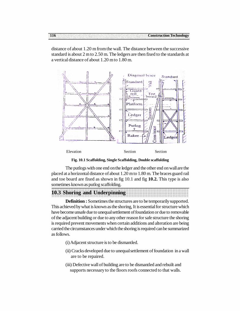
Construction Technology116
distance of about 1.20 m from the wall. The distance between the successivestandard is about 2 m to 2.50 m. The ledgers are then fixed to the standards ata vertical distance of about 1.20 m to 1.80 m.
Elevation Section Section
Fig. 10.1 Scaffolding, Single Scaffolding, Double scaffolding
The putlogs with one end on the ledger and the other end on wall are theplaced at a horizontal distance of about 1.20 m to 1.80 m. The braces guard railand toe board are fixed as shown in fig 10.1 and fig 10.2. This type is alsosometimes known as putlog scaffolding.
10.3 Shoring and UnderpinningDefinition : Sometimes the structures are to be temporarily supported.
This achieved by what is known as the shoring, It is essential for structure whichhave become unsafe due to unequal settlement of foundation or due to removableof the adjacent building or due to any other reason for safe structure the shoringis required prevent movements when certain additions and alteration are beingcarried the circumstances under which the shoring is required can be summarizedas follows.
(i) Adjacent structure is to be dismantled.
(ii) Cracks developed due to unequal settlement of foundation in a wall are to be repaired.
(iii) Defective wall of building are to be dismantled and rebuilt and supports necessary to the floors roofs connected to that walls.
117Paper - I Construction Practice
(iv) Large openings are required to be made in the main walls of an existing buildings.
(v) Walls of a building showing signs of bulging out or leaning outwards due to bad workmanship .
1. Material : The shoring can be carried out either in timber or in steeltubes or in combination of timber and steel tubes. The timber surface should becoated with a preservative so as to give protection against wet rot.
2. Duration : There is no limit for the duration of shoring and it rangesfrom weeks to years.
3. Requirement : The loads coming on shoring vary widely in natureand hence the requirement of each case of shoring be studied separately anddesigned accordingly.
4. Approval : The shoring should be carried out as per prevailing rulesand regulations of the local authority and necessary approval should be obtained.
10.3.1 Types of Shoring
Depending their supporting characteristics , the shores are classifiedinto the following three categories
1. Ranking or inclined shores
2. Flying or horizontal shores
3. Dead or vertical shores.
10.3.2 Under Pining
Definition : The placing of new foundation below an existing foundationor the process of strengthening the existing foundation is known as the underpinning of foundation .
Following are the situation demanding underpinning
(i) A building with deep foundation is to be contructed adjoining to an existing building.
(ii) Settlement of existing foundation has taken place, resulting in serious cracks in the wall.
(iii) The basement is to be provided to an existing building.
(iv) The existing foundation are to be deepened so as to rest them on soil of higher power.
Construction Technology118
Points of be attended to before under pinning
Following important points should be carefully attended to before thework of under pinning commences.
1. Shoring and Strutting : The necessary shoring and strutting shouldbe provided to the structure to make it safe for carrying out the process ofunderpinning.
2. Examination of structure : The structure should be carefullyexamined before under pinning is commenced and poor masonry work shouldbe suitably rectified.
3. Repairs : It is necessary to carry out urgent repair such as groutingof cracks insertion of tie rods between walls, etc before commencing underpinning.
4. Checking arrangement : The levels may be marked on the structureand the movement of structure during under pinning should be checked andrecorded.
5. Expensive operation : The process of underpinning is an art ratherthan a science . Due to advance made in the science of soil machines, muchguess-work in underpinning is eliminated . But still is remains an expensiveoperation.
6. Bearing Plate : When R.S. joist is used as needle, the bearing plateis provided a void the crushing of masonry.
Methods of Under Pining
Following are the methods of under pining
1. Pit method
2. Pile method
3. Miscellaneous method
10.3.3 In this method
The existing wall is divided into suitable section of width about 1.20 mto 1.50m.
The holes are then made in the existing wall. The needles with bearingplates are then inserted through these holes and supported on jacks as shown inFig 14-2 .The pit is excavated and the existing foundation is taken up to therequired level. Following precautions are necessary :
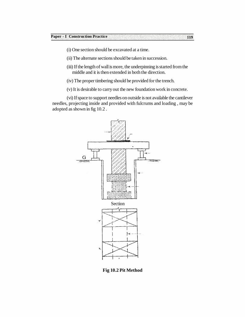
119Paper - I Construction Practice
(i) One section should be excavated at a time.
(ii) The alternate sections should be taken in succession.
(iii) If the length of wall is more, the underpinning is started from the middle and it is then extended in both the direction.
(iv) The proper timbering should be provided for the trench.
(v) It is desirable to carry out the new foundation work in concrete.
(vi) If space to support needles on outside is not available the cantileverneedles, projecting inside and provided with fulcrums and loading , may beadopted as shown in fig 10.2 .
Fig 10.2 Pit Method
Section
Construction Technology120
SummaryScaffolding : scaffolding is a temporary framework of timber or steel
elements having plat forms at different levels to enable the masons to work atdifferent heights of a buildings.
Shoring : Structures are to be temporary supported . This is known asshoring.
Underpinning : The placing of new foundation below an existingfoundation is known as underpinning of foundation.
Short Answer Type Questions1. Define scaffolding.
2. Define shoring.
3. Define underpinning.
4. Mention the types of scaffolding.
5. Mention the types of underpinning.
6. Mention the types of shoring.
On The Job Training
1. The student should visit the sites of masonry work, which are under construction.
2. Record the scaffolding work.
Structure11.1 Technical term
11.2 Classification of Joints
11.3 Tools used in carpentry
Learning objectivesAfter studying this unit the student should be able to understand about
• Technical terms in carpentry
• Classification of Joints carpentry
• Tools used in Carpentry
11.1 Technical termsThe following are the technical terms commonly used in carpentry.
1. Batten : The narrow strip of wood which sir nailed over the joints ofboards is known as batten .
2. Bead : This is a semi-circular projection which is formed on thedegrees or surface of wood. It is used at the joints of straight boards to avoidthe unsightly appearance of the joint in case of shrinkage of wood. The fourterm of bead namely, single quirked bead, double quirked flush bead, cockbead and cock bead with are respectively shown.
11UNIT
Carpentry and Joinery
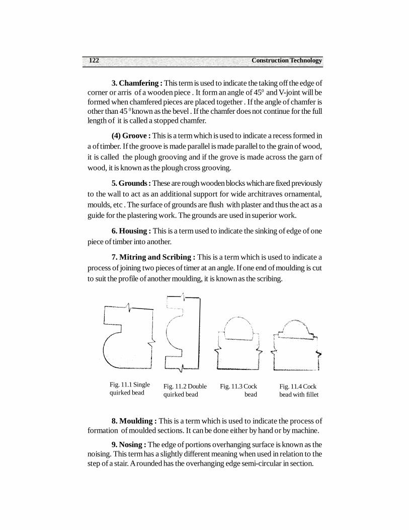
Construction Technology122
3. Chamfering : This term is used to indicate the taking off the edge ofcorner or arris of a wooden piece . It form an angle of 450 and V-joint will beformed when chamfered pieces are placed together . If the angle of chamfer isother than 45 0 known as the bevel . If the chamfer does not continue for the fulllength of it is called a stopped chamfer.
(4) Groove : This is a term which is used to indicate a recess formed ina of timber. If the groove is made parallel is made parallel to the grain of wood,it is called the plough grooving and if the grove is made across the garn ofwood, it is known as the plough cross grooving.
5. Grounds : These are rough wooden blocks which are fixed previouslyto the wall to act as an additional support for wide architraves ornamental,moulds, etc . The surface of grounds are flush with plaster and thus the act as aguide for the plastering work. The grounds are used in superior work.
6. Housing : This is a term used to indicate the sinking of edge of onepiece of timber into another.
7. Mitring and Scribing : This is a term which is used to indicate aprocess of joining two pieces of timer at an angle. If one end of moulding is cutto suit the profile of another moulding, it is known as the scribing.
8. Moulding : This is a term which is used to indicate the process offormation of moulded sections. It can be done either by hand or by machine.
9. Nosing : The edge of portions overhanging surface is known as thenoising. This term has a slightly different meaning when used in relation to thestep of a stair. A rounded has the overhanging edge semi-circular in section.
Fig. 11.1 Singlequirked bead
Fig. 11.2 Doublequirked bead
Fig. 11.3 Cock bead
Fig. 11.4 Cockbead with fillet
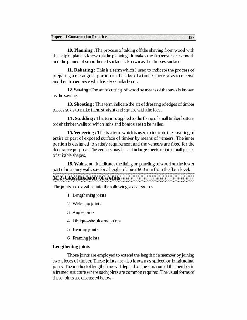
123Paper - I Construction Practice
10. Planning :The process of taking off the shaving from wood withthe help of plane is known as the planning . It makes the timber surface smoothand the planed of smoothened surface is known as the dresses surface.
11. Rebating : This is a term which I used to indicate the process ofpreparing a rectangular portion on the edge of a timber piece so as to receiveanother timber piece which is also similarly cut.
12. Sewing :The art of cutting of wood by means of the saws is knownas the sawing.
13. Shooting : This term indicate the art of dressing of edges of timberpieces so as to make them straight and square with the face.
14 . Studding : This term is applied to the fixing of small timber battenstot eh timber walls to which laths and boards are to be nailed.
15. Veneering : This is a term which is used to indicate the covering ofentire or part of exposed surface of timber by means of veneers. The innerportion is designed to satisfy requirement and the veneers are fixed for thedecorative purpose. The veneers may be laid in large sheets or into small piecesof suitable shapes.
16. Wainscot : It indicates the lining or paneling of wood on the lowerpart of masonry walls say for a height of about 600 mm from the floor level.
11.2 Classification of JointsThe joints are classified into the following six categories
1. Lengthening joints
2. Widening joints
3. Angle joints
4. Oblique-shouldered joints
5. Bearing joints
6. Framing joints
Lengthening joints
Those joints are employed to extend the length of a member by joiningtwo pieces of timber. These joints are also known as spliced or longitudinaljoints. The method of lengthening will depend on the situation of the member ina framed structure where such joints are common required. The usual forms ofthese joints are discussed below .
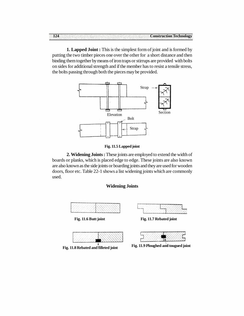
Construction Technology124
1. Lapped Joint : This is the simplest form of joint and is formed byputting the two timber pieces one over the other for a short distance and thenbinding them together by means of iron traps or stirrups are provided with boltson sides for additional strength and if the member has to resist a tensile stress,the bolts passing through both the pieces may be provided.
Fig. 11.5 Lapped joint
2. Widening Joints : These joints are employed to extend the width ofboards or planks, which is placed edge to edge. These joints are also knownare also known as the side joints or boarding joints and they are used for woodendoors, floor etc. Table 22-1 shows a list widening joints which are commonlyused.
Widening Joints
Strap
SectionElevation
Strap
Bolt
Fig. 11.6 Butt joint Fig. 11.7 Rebated joint
Fig. 11.9 Ploughed and tougued jointFig. 11.8 Rebated and filleted joint
125Paper - I Construction Practice
Tables Used
Widening Joints
Fastening
The fastening which are commonly employed to secure timber joints inposition are briefly described below.
S.No.
1
2
3
4
5
6
7
8
9
10
Name of Joint
Butt joint
Rebated joint
Rebated and filletedjoint
Ploughed andtongued joint
Tongued andgrooved joint
Rebated tongued andgrooved Joints
Splayed Joint
Dowelled joint
Matched and beadedjoint
Matched and -jointed join
Remarks
This is also known as the straight , plain orsquare joint and it is Used for ordinarypurpose.
This joint remains dust-proof after theshrinkage of timber.
A small piece of wood, called the fillet, isintroduced in The rebated portion. This jointis used for floors where heavy wear isexpected such as factories, stores etc.
A fillet is provided into the grooves . Thisjoint requires more Labour. But it forms anexcellent joint.
This joint is used for work of superior nature.
This joint is used for secret nailing that is,for placing the nail heads in such a way thatthey cannot be seen .
This joint is used for ordinary purpose.
The dowels which are small pieces of hardstone, slate gunmetal Brass bronze orcopper are used to form this joint.
This joint used to avoid unsightly appearancedue to the Shrinkage of timber .
This joint is just similar to above except thatinstead of being Beaded, it is chamfered inthe shape of V.
Construction Technology126
1. Bolts : One end of the bolt is formed of a solid head and at the otherend of the shank, the threads are provided on which a nut moves . The washesare flat disc of iron and they are placed under the nut as shown. The washersprevent the possible injury by nut to the timber when nut is pressed.
2. Pins : These are the small pieces of timber which can used tostrengthen the joint.
3 screw : These are used under the following circumstances
(i) The work is likely to be removed.
(ii) The security of work is required without making the joint unnecessarily rigid.
(iii) The driving of a nail is likely to split the timber.
(iv) The wok is to be done in pieces.
(v) The joint is subjected to the vibrations.
The various forms of screws are available and they may be of copper,brass steel or wrought iron.
• Shows and ordinary screw.
• Show a coach screw which has a square or hexagonal head so that a spanner can be used to turn it.
A handrdail screw which has threads at both the ends. At one end asquare nut is attached and the other end is provided with a circular nut slottedon the edge.
Fig. 11.10 Ordinary screw Fig. 11.11 Coach screw Fig. 11.12 Handrail screw
127Paper - I Construction Practice
3. Sockets : These are the pieces of wrought or cast-iron and are usedto protect the ends of timber. When sockets are placed at the feet of members,they are known as the shoes.
4. Spikes : These are large nails of length about 100 mm to 150 mmand they are used for heavy work.
5. Straps : These are bands of steel or wrought iron which can be usedfor to join two pieces of timber. The breadth of strap is about 40 mm to 50 mmand its thickness depends upon the stress coming upon it. The great advantageof a strap is that the timber is not required to be cut and thus the timber is notweakened.
6. Wedges : These are the pieces of wood which are tapered and areused for securing timber joints as in case of mortise and tendon joint. They aresometimes known as the keys and when used in parts they are termed as thefolding wedges.
11.3 Tools used in carpentryTable shows a list f tools required by a carpenter. The sketches of some
of the tools are already given in chapter 10 of stone masonry and hence thecorresponding numbers are mentioned .
Tools used in carpentry
Name of tool
1.Boring tools
AugerAuger bit
Centre bit
Rose counter sunk bidScrew-driver bit
Brace
Bradawl
Gimlet
2. Cutting tools
Compass saw
Remarks
This is used for deep boring
These are used to prepare the holes of different shapes
A bit is attached at is lower end and hole is bored byhand press
This has a sharpened end
This is small tool used for making and boring small holes
The various forms of saw and chisel are used to cut thetimber
Construction Technology128
Summary1. The term carpentry includes such forms of construction which have to resist stresses to due to loads coming upon them.
2. The form joinery is used to indicate fittings art of preparing internal fittings and finishing of timber.
3. The joiner constructs timbers works such as door, windows, stairs, floor boards, furniture, cupboards etc.
4. The workman also is employed for the work is known as carpenter.
Coping sawCross-cut-sawHand sawFirmer chiselMortise chiselParing chisel
3. Hammer
Claw hammerSpall hammerWaller’s hammer
4. Marking tools
Bevel, Markinggauge, Spirit levelSquare
5. Planning tools
Bead plane, Jackplane, Rebate plan
6. Miscellaneoustools
Cramp, Nail punchOil stone PincersPliers Screw –driver
The various forms of hammer are used to drive thenails and for forming Joints
These tools are required to mark lines on the wood.
The various forms of plane are used to make the surfaceof timber Smooth and to form small moldings.
These tools make the carpenter’s work speedy andeasy
129Paper - I Construction Practice
5. The joints are classified as follows
1. Lengthening joints
2. Oblique shouldered joints
3. Widening joints
4. Bearing joints
5. Angle joints
6. Framing joints
Short Answer Type Questions1. Define carpentry.
2. Define Joinery.
3. Define Carpenter.
4. Mention the types of Joints.
5. Write the tools used in carpentry .
On The Job Training
1. Student should visit the site of carpentry work observe and record the different joints, tools used in carpentry.
Construction Technology130
Structure12.0 Introduction
12.1 Plastering
12.2 Procedure of plastering
12.3 Pointing
12.4 Painting
Learning ObjectivesAfter completing this unit the student should be able to understand about
• Purpose of plastering, pointing and panting
• Types of plastering, pointing and painting
• Procedure of plastering pointing and pointing
12.0 Introduction
Masonry structures after their construction require interior and exteriorfinishing or protective coatings. These finishings shall increase the life and strengthof the structure and at the same time enhance the appearance. Other finishingsinclude white washing, colour washing, painting, distempering etc. Thesefinishing are also called as “surface rendering”.
12UNIT
Surface Finishing
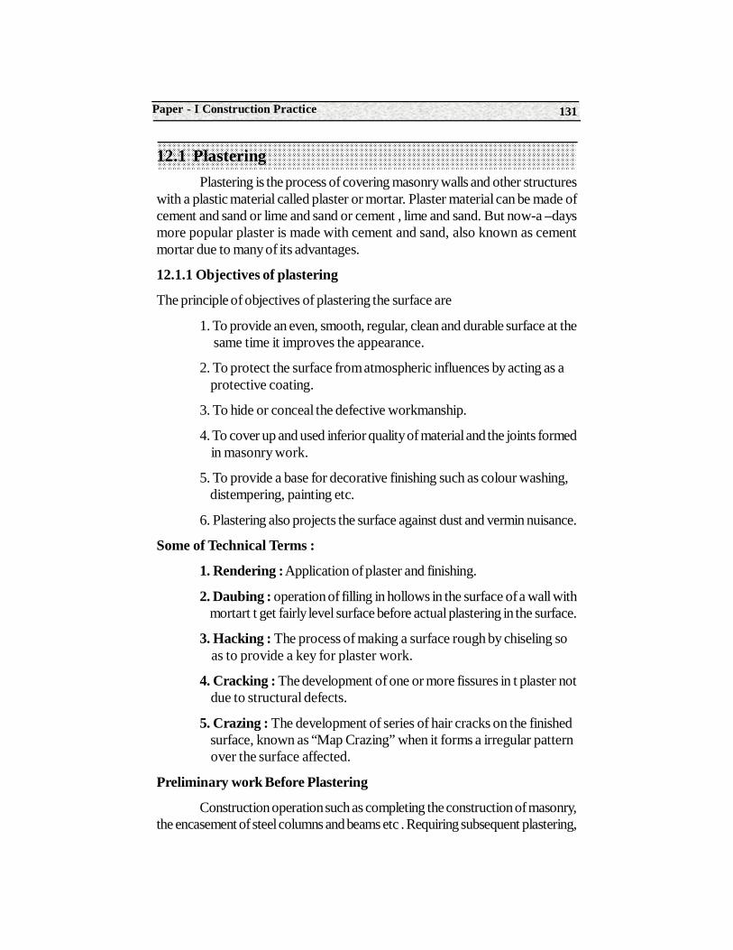
131Paper - I Construction Practice
12.1 PlasteringPlastering is the process of covering masonry walls and other structures
with a plastic material called plaster or mortar. Plaster material can be made ofcement and sand or lime and sand or cement , lime and sand. But now-a –daysmore popular plaster is made with cement and sand, also known as cementmortar due to many of its advantages.
12.1.1 Objectives of plastering
The principle of objectives of plastering the surface are
1. To provide an even, smooth, regular, clean and durable surface at the same time it improves the appearance.
2. To protect the surface from atmospheric influences by acting as a protective coating.
3. To hide or conceal the defective workmanship.
4. To cover up and used inferior quality of material and the joints formed in masonry work.
5. To provide a base for decorative finishing such as colour washing, distempering, painting etc.
6. Plastering also projects the surface against dust and vermin nuisance.
Some of Technical Terms :
1. Rendering : Application of plaster and finishing.
2. Daubing : operation of filling in hollows in the surface of a wall with mortart t get fairly level surface before actual plastering in the surface.
3. Hacking : The process of making a surface rough by chiseling so as to provide a key for plaster work.
4. Cracking : The development of one or more fissures in t plaster not due to structural defects.
5. Crazing : The development of series of hair cracks on the finished surface, known as “Map Crazing” when it forms a irregular pattern over the surface affected.
Preliminary work Before Plastering
Construction operation such as completing the construction of masonry,the encasement of steel columns and beams etc . Requiring subsequent plastering,
Construction Technology132
shall be programmed that they are sufficiently cured and dry to receive the plasterwithout further damage to plaster or decoration o the plaster.
Preparation of surface
1. Roughening : The roughening of the background improves the bondof plaster. This is particularly important in case of soffit ceiling. A smooth surfaceshall be roughened by wire brushing if it is not hard or by hacking if it is hard. Alljoints shall be thoroughly raked. After roughening, care shall be taken to moistenthe surface sufficiently before plastering. Otherwise the freshly exposed dry surfacemay absorb considerable amount of water from the plaster.
2. Cleaning : The surface to be plastered shall be thoroughly brushedto remove dust, loose particle s of mortar etc ., or efflorescence where it hasoccurred.
3. Daubing : Daubing shall be necessary where the background is veryuneven that unevenness cannot made up in regular coat of plastering. The processof daubing consist in filing the holes and depression with mortar of the same mixas per the first coat. The patches of plaster thus done are left rough so that thesubsequent coat plaster would stick to it.
4. Wetting : The surface shall be wetted evenly before applying theplaster. Care shall be taken to see that the surface is not to dry as this , maycause lack of adhesion or excessive absorption of water from the plaster. As faras possible, the plaster work shall be done under shade.
5. Control of cracking : In case of discontinuity in backgrounds thetwo portions shall be separated by a near cut or groove at the junction. Wheresuch cutting or grooving is not participle the plaster at such location by reinforcedby providing a suitable scrim of jute or wire gauge etc.
6. Control of surface crazing : Sufficient time intervals shall be providedbetween successive coasts so that each under goes it shrinkage before the nextcoat is applied. Care shall be taken to prevent rapid drying of the final or finishingcoat.
Tools for plastering
Following tool. Are generally used for the plastering work
(i) Gauging trowel : This is the ordinary trowel and is useful for applying mortar to mouldings, corners etc. It has a pointed or bull-nosed end.
(ii) Float : This is tool is used for to spread the mortar on the surface . It is made of thin tempered steel. It is also known as the laying trowel. The wooden float is known as the Skimming Float and sis used for
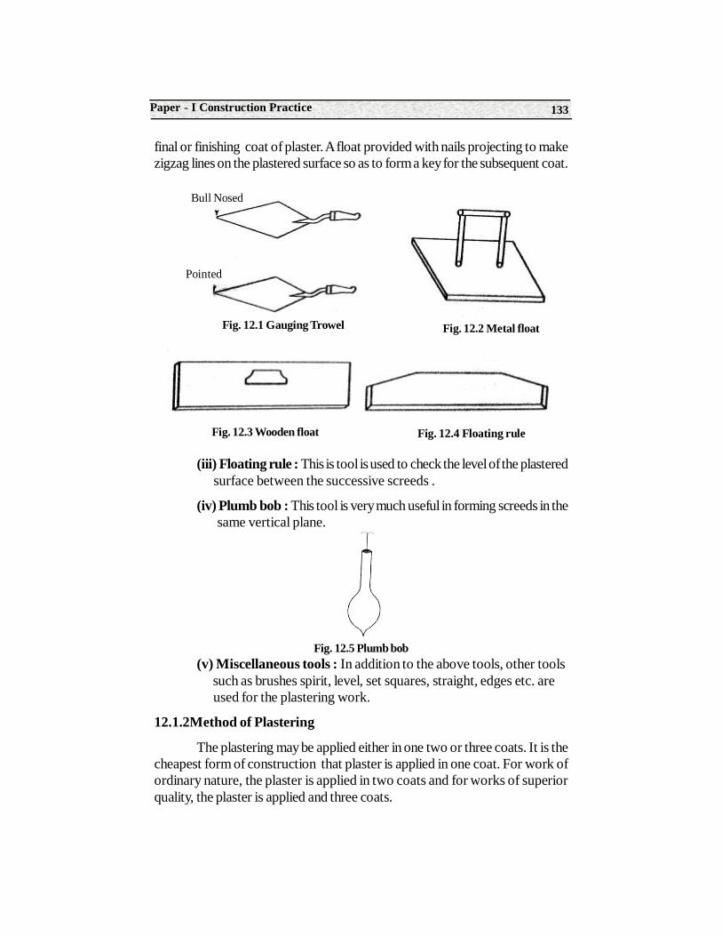
133Paper - I Construction Practice
final or finishing coat of plaster. A float provided with nails projecting to makezigzag lines on the plastered surface so as to form a key for the subsequent coat.
(iii) Floating rule : This is tool is used to check the level of the plastered surface between the successive screeds .
(iv) Plumb bob : This tool is very much useful in forming screeds in the same vertical plane.
Fig. 12.5 Plumb bob(v) Miscellaneous tools : In addition to the above tools, other tools such as brushes spirit, level, set squares, straight, edges etc. are used for the plastering work.
12.1.2Method of Plastering
The plastering may be applied either in one two or three coats. It is thecheapest form of construction that plaster is applied in one coat. For work ofordinary nature, the plaster is applied in two coats and for works of superiorquality, the plaster is applied and three coats.
Bull Nosed
Pointed
Fig. 12.2 Metal float
Fig. 12.4 Floating ruleFig. 12.3 Wooden float
Fig. 12.1 Gauging Trowel
Construction Technology134
12.2 Procedure of plasteringAs per A.PD.S.S, cement mortar (1:4) shall be used to plastering work
unless it is mentioned specifically. Generally the ingredients i.e., cement andsand are proportioned on volume basis and then mixed thoroughly. Each bag ofPortland cement weighs 50 kg., and by volume each bag O.P.C is equal to0..35 cu meters . In other word , weight of cement for a volume of 1 cu meter isequal to 1440 kg. Wooden boxes of standard sizes shale b used for mixing sandwith cement.
Mixing : For large works, mixing shall be done preferably in a mechanicalmixer by adding cement adding cement and sand in specified proportion andmixed thoroughly in dry state. Water shall then be added gradually and wetmixing continued at least for 3 minutes. Care shall be taken not to add morewater than that required to prepare the mortar of suitable working consistency.
The plastering with cement mortar shall be done in the same manner asdescribed in lime mortar plastering. Bur final rendering shall be appliedimmediately after plastering is completed.
Neat Portland cement slurry with a cram like consistency is applied asthinly and uniformly as possible with trowel and rubbed smooth.
12.2.1 Plastering with cement mortars, two coats 20 mm thick with spongefinish.
Cement mortar for the first coat shall be prepared in specified proportionas described in previous case. The mortar for the second coat shall be madewith fine sand, passing through is sieves of 150 and 600 microns of the specifiedproportion.
Application of first coat : The fist coat of cement mortar in specifiedproportion shall be applied as mentioned in lime mortar plastering except thatcement mortar 17 mm thick shall be applied. The plastered surface after floatingis gain raked to provide a proper bond for the second coat.
Application of Second coat : Cement mortar with fine sand as indicatedabove shall be prepared in the form of thick cream like consistency. This isapplied over the first coat surface prepared with trowel to a thickness of 3 mm. It is then floated with a long wooden float to make the surface true. Then theentire surface is lightly rubbed with wet sponge and then daubed with spongessqueezed dry to get the required finish.
When it is not possible to apply the second coat when the first coat isgreen , the first coat shall be cured for at least two weeks before it is permittedto fry. Before the second coatis applied, the surface shall be thoroughly scrubbed
135Paper - I Construction Practice
and washed clean to remove dust and other loose particles. The surface shall bethoroughly wetted before applying the second coat. The finish surface shall becured for a minimum period of two weeks
12.3 Pointing Pointing is defined as the finishing of masonry joints with a rich mortars
and in decorative manner. Pointing is applied when it is desired to exhibit thematerial of the masonry, when the material used in the masonry is capable ofresisting the atmospheric action .
12.3.1 Objects of pointing
Following are the main objects for providing pointing and plastering tothe exposed surfaces
(i) To improve the appearance of the structure as a wheel and to give smooth surface.
(ii) To protect the exposed surface from the effects of atmospheric actions.
(iii) To rectify the defective workmanship or a conceal inferior materials.
Types of Pointing
(a) Flush pointing
(b) Raised and cut pointing
(c) Line or groove pointing
(d) Struck pointing
(e) Tuck pointing
(a) Flush pointing : The mortar shall be pressed into the joints andshall be finished and level with the edges of bricks tiles or stones so as to give asmooth appearance. The edges shall be neatly trimmed with trowel and straight.
(b) Raised and cut pointing : Raised and cut pointing shall projectfrom the wall facing with it edges cur parallel so as to have a uniformly raisedband about 6 mm raise and width 10mm. The pointing shall be finished to asmooth but hard surface.
(c) Line or groove pointing : The joint shall be initially formed as forflush pointing. While the mortar is still green, a groove of specified size andshape shall be formed by running a groove forming tool along the centre line of
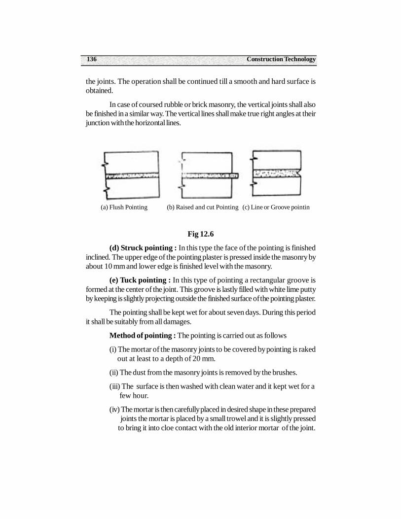
Construction Technology136
the joints. The operation shall be continued till a smooth and hard surface isobtained.
In case of coursed rubble or brick masonry, the vertical joints shall alsobe finished in a similar way. The vertical lines shall make true right angles at theirjunction with the horizontal lines.
Fig 12.6
(d) Struck pointing : In this type the face of the pointing is finishedinclined. The upper edge of the pointing plaster is pressed inside the masonry byabout 10 mm and lower edge is finished level with the masonry.
(e) Tuck pointing : In this type of pointing a rectangular groove isformed at the center of the joint. This groove is lastly filled with white lime puttyby keeping is slightly projecting outside the finished surface of the pointing plaster.
The pointing shall be kept wet for about seven days. During this periodit shall be suitably from all damages.
Method of pointing : The pointing is carried out as follows
(i) The mortar of the masonry joints to be covered by pointing is raked out at least to a depth of 20 mm.
(ii) The dust from the masonry joints is removed by the brushes.
(iii) The surface is then washed with clean water and it kept wet for a few hour.
(iv) The mortar is then carefully placed in desired shape in these prepared joints the mortar is placed by a small trowel and it is slightly pressed to bring it into cloe contact with the old interior mortar of the joint.
(a) Flush Pointing (b) Raised and cut Pointing (c) Line or Groove pointin
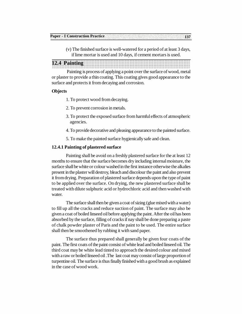
137Paper - I Construction Practice
(v) The finished surface is well-watered for a period of at least 3 days, if lime mortar is used and 10 days, if cement mortars is used.
12.4 Painting Painting is process of applying a point over the surface of wood, metal
or plaster to provide a thin coating. This coating gives good appearance to thesurface and protects it from decaying and corrosion.
Objects
1. To protect wood from decaying.
2. To prevent corrosion in metals.
3. To protect the exposed surface from harmful effects of atmospheric agencies.
4. To provide decorative and pleasing appearance to the painted surface.
5. To make the painted surface hygienically safe and clean.
12.4.1 Painting of plastered surface
Painting shall be avoid on a freshly plastered surface for the at least 12months to ensure that the surface becomes dry including internal moisture, thesurface shall be white or colour washed in the first instance otherwise the alkaliespresent in the plaster will destroy, bleach and discolour the paint and also preventit from drying. Preparation of plastered surface depends upon the type of paintto be applied over the surface. On drying, the new plastered surface shall betreated with dilute sulphuric acid or hydrochloric acid and then washed withwater.
The surface shall then be given a coat of sizing (glue mixed with a water)to fill up all the cracks and reduce suction of paint. The surface may also begiven a coat of boiled linseed oil before applying the paint. After the oil has beenabsorbed by the surface, filling of cracks if nay shall be done preparing a pasteof chalk powder plaster of Paris and the paint to be used. The entire surfaceshall then be smoothened by rubbing it with sand paper.
The surface thus prepared shall generally be given four coats of thepaint. The first coats of the paint consist of white lead and boiled linseed oil. Thethird coat may be white lead tinted to approach the desired colour and mixedwith a raw or boiled linseed oil .The last coat may consist of large proportion ofturpentine oil. The surface is thus finally finished with a good brush as explainedin the case of wood work.
Construction Technology138
Readymade or ready mixed paint are also available in market whichcan be applied directly on the newly plastered surfaces.
Painting old plastered surface : If the oil paints is firm and sound itshall be cleaned of grease smoke etc. and then all dust, dirt and loose particlesof paint shall be removed.
If the old paint is badly blistered and flaked ,it is shall be completelyremoved by using and type of paint remover. If may portion d the walls showssigns of dampness , the cause shall be investigated and the damp surface shallbe properly treated. A thin coat of white lead the damp surface shall be properlytreated. A thin coat of white of lead if required shall be applied on the wet orpatchy portion of the surface before painting is undertaken.
Application of new paints shall be carried out as specified in previouscase i.e. in similar way as described for new plastered surface.
12.4.2 Painting on different surface
The process of painting on the nature if the surface to be painted . Abrief description of painting on each of the various surface is given below :
1. New wood work : Normally four coats of paint are required for new woodwork .
The process of painting is carried out as follows
(i) The surface of woodwork is prepared to receive the paint. Forsatisfactory working it is necessary that the woodwork is sufficiently seasonedand it does not contain more than 15 percent moisture at the time of painting .The surface of woodwork is thoroughly cleaned and the heads of nails arepunched to a depth of 3 mm below the surface.
(ii) The surface of the woodwork is then knotted.
(iii) The printing coat is then applied on the surface of new woodwork .Generally the printing coat is applied before the woodwork is placed in position.
(iv) The process o stopping is then carried out.
(v) The subsequent coats of paint , namely, under coats and finishingcoats are then applied on the surface. The extreme surface should be taken tosee that the finishing coat presents smooth and even surface and that no brushmarks are seen on the finished work.
2. Repainting of woodwork : If the paint on the old wood work hascracked or has developed blister, it is to be removed .If the surface has becomegreasy, it should be cleaned by rubbing down sand paper or fine pumice stone.
139Paper - I Construction Practice
The old paint can also be removed by applying any one of the following threepaint solvents.
(i) A solution containing of one part of soft soap and two parts of potashis prepared and one used to wash the surface. The paint dissolves and thesurface becomes clean.
(ii) A mixture consisting of one part of soft soap and two parts of potashis prepared and one part of quickness is then added afterwards. This mixture isapplied on the surface in a hot state and allowed to stay for about 24 hours. Thesurface is then washed with hot water.
(iii) A mixture consisting of equal part of washing soda and quicklime isbrought to a paste form by adding required quantity of water . It Is applied onthe surface and kept for about an hour . The surface is then washed with water.
After removing old paint from the surface, the wooden work is paintedas in case of painting on new woodwork.
3. New iron work and steelwork : The surface of iron or steel toreceive the paint should be free from rust, grease ,dirt etc. The suitable equipmentsuch as wire brushed , scraper , etc. are used to remove all loose marks etc.From the surface the water with caustic soda or lime is used to removed grease.The cleaned surface is provided with a film phosphoric acid. This film protectsthe surface from rust and it also facilities the adhesion of paint. The coats ofpaint are the n applied .
The paint suitable to iron and steel surface should be selected for eachcoat. The finishing coat should present a smooth finish and precaution should betaken to avoid the presence of brush marks on the final painted surface.
4. Repainting old iron work and steel work : The old surface shouldbe thoroughly cleaned by the application of soap-water and if grease if present,it should be removed by washing the surface with lime and water. If it necessaryto remove old paint, the surface be burnt, usually by a blow lamp and then oldpaint should be scraped off or dissolved and removed by using any paint solvent.After the surface is thus prepared, the painting is carried out as in case of newironwork or steelwork.
Summary• Plastering is the process of covering walls and other structures with a binding material called plaster or worker.
• Plaster material can be made of cement and sand, also known as cement mortar.
Construction Technology140
• Pointing is used to denote the finishing of mortar joints of either stone masonry or brick masonry.
• Main objective s of pointing
• To improve the appearance of the structure
• To provide the exposed surface from the effects of atmospheric actions
• To rectify defective workmanship
• Main objects of plastering
• To provide an even ,smooth, regular, clean and durable surface
• To improve the appearance
• To protect the surface from atmospheric actions
• To provide a base for decorative finishing such as colour washing distempering painting etc
Tool used for plastering
1. Pump bob
2. Float
3. Floating rule
4. Trowel
5. Brushes
6. Spirit ravel
7. Straight edges
Methods of plastering
Mastering may be applied
• One coat
• Two coat
• Three coat
• Types of pointing
• Beaded pointing
141Paper - I Construction Practice
• Flush pointing
• Recessed pointing
• Grooved pointing
• Struck pointing
• Tuck pointing
• Vee-pointing
Short Answer Type Questions1. Define plastering.
2. Define pointing.
3. Write the objectives of plastering .
4. Mention methods of pointing.
5. Define the following .
(i) Rentering
(ii) Daubing
(iii) Hacking
(iv) Cracking
(v) Crazing
6. Define painting.
7. Mention the objects of paintings.
8. Explain flush pointing.
Long Answer Type Questions1. Explain the method of preparation of surface masonry before plastering.
2. Explain the method of plastering write cement mortar one coat 12 mm thick.
3. Describe the method of painting on wood surface.
4. Describe the method of painting on metal surface.
Construction Technology142
On The Job Training
1. The student should visit the sites of building construction and observed the plastering and pointing works of masonry .
2. The student should visit the sites of painting work and wood works of new and old.
3. And also the student should maintain the record of different site visit
Structure13.0 Introduction
13.1 Bull Dozer
13.2 Concrete mixers
13.3 Cranes
13.4 Pully Blocks
13.5 Pumps
13.6 Winches
13.7 Excavator
Learning objectivesAfter studying this unit the student should be able to understand about
various types of construction equipment and their purposes .
13.0 Introduction
In the construction work, construction equipment of different type arereqruired to suit the nature of work. These equipment are to be collected andkept in workable condition so as not to obstruct the progress of work. Thesuccess of a construction project entirely depends upon the choice of mechanicalequipment and if the choice is proper, the work can be completed in short time
13UNIT
Basic knowledge of equipmentand Construction machinery
Construction Technology144
with less cost. As a matter of fact, easy availability of good mechanical equipmentproves to be an asset of any civil engineering project.
The knowledge of construction equipment is required to
(i) Make construction planning
(i) Prepare work table
(iii) Select right type and number of equipment
(iv) Run all the equipment continuously, economically and efficiently and
(v) Improve speed, quality, consistency and economy of construction by selecting the suitable equipment.
Various types of construction equipment
Following are the different types of construction equipment
1. Excavating equipment
2. Earth compaction equipment
3. Hauling equipment
4. Hoisting equipment
5. Conveying equipment
6. Pumping equipment
7. Concrete construction equipment
8. Drilling equipment
9. Road making equipment
13.1 Bull Dozer(i) Purposes of bulldozer : A bulldozer is very useful equipment and
can be used in the construction work for the following purposes :
(a) To clear the site of work
(b) To make the land level
(c) To prepare pilots roads throug hmountains and hard ground and
(d) To excavate the material and haul for a distance of about 100 meters
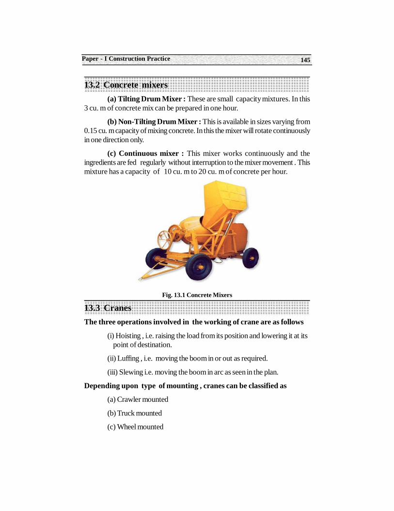
145Paper - I Construction Practice
13.2 Concrete mixers(a) Tilting Drum Mixer : These are small capacity mixtures. In this
3 cu. m of concrete mix can be prepared in one hour.
(b) Non-Tilting Drum Mixer : This is available in sizes varying from0.15 cu. m capacity of mixing concrete. In this the mixer will rotate continuouslyin one direction only.
(c) Continuous mixer : This mixer works continuously and theingredients are fed regularly without interruption to the mixer movement . Thismixture has a capacity of 10 cu. m to 20 cu. m of concrete per hour.
Fig. 13.1 Concrete Mixers
13.3 CranesThe three operations involved in the working of crane are as follows
(i) Hoisting , i.e. raising the load from its position and lowering it at its point of destination.
(ii) Luffing , i.e. moving the boom in or out as required.
(iii) Slewing i.e. moving the boom in arc as seen in the plan.
Depending upon type of mounting , cranes can be classified as
(a) Crawler mounted
(b) Truck mounted
(c) Wheel mounted
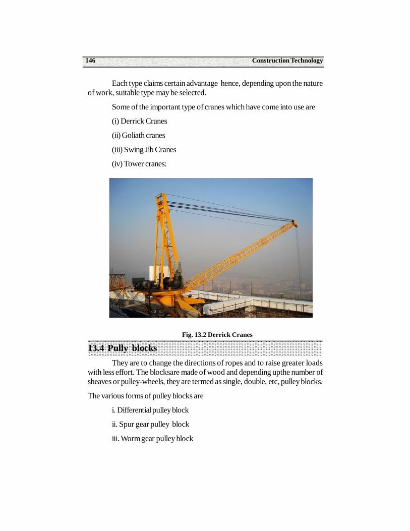
Construction Technology146
Each type claims certain advantage hence, depending upon the natureof work, suitable type may be selected.
Some of the important type of cranes which have come into use are
(i) Derrick Cranes
(ii) Goliath cranes
(iii) Swing Jib Cranes
(iv) Tower cranes:
Fig. 13.2 Derrick Cranes
13.4 Pully blocksThey are to change the directions of ropes and to raise greater loads
with less effort. The blocksare made of wood and depending upthe number ofsheaves or pulley-wheels, they are termed as single, double, etc, pulley blocks.
The various forms of pulley blocks are
i. Differential pulley block
ii. Spur gear pulley block
iii. Worm gear pulley block
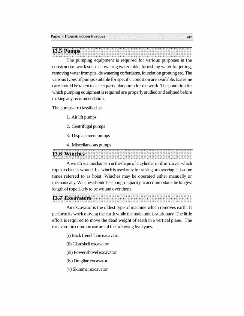
147Paper - I Construction Practice
13.5 PumpsThe pumping equipment is required for various purposes in the
construction work such as lowering water table, furnishing water for jetting,removing water from pits, de watering cofferdams, foundation grouting etc. Thevarious types of pumps suitable for specific condition are available. Extremecare should be taken to select particular pump for the work, The condition forwhich pumping equipment is required are properly studied and anlysed beforemaking any recommendation.
The pumps are classified as
1. Air lift pumps
2. Centrifugal pumps
3. Displacement pumps
4. Miscellaneous pumps
13.6 Winches
A winch is a mechanism in theshape of a cylinder or drum, over whichrope or chain is wound. If a winch is used only for raising or lowering, it issometimes referred to as hoist. Winches may be operated either manually ormechanically. Winches should be enough capacity to accommodate the longestlength of rope likely to be wound over them.
13.7 Excavators
An excavator is the oldest type of machine which removes earth. Itperform its work moving the earth while the main unit is stationary. The littleeffort is required to move the dead weight of earth in a vertical plane. Theexcavator in common use are of the following five types.
(i) Back trench hoe excavator
(ii) Clamshell excavator
(iii) Power shovel excavator
(iv) Dragline excavator
(v) Skimmer excavator
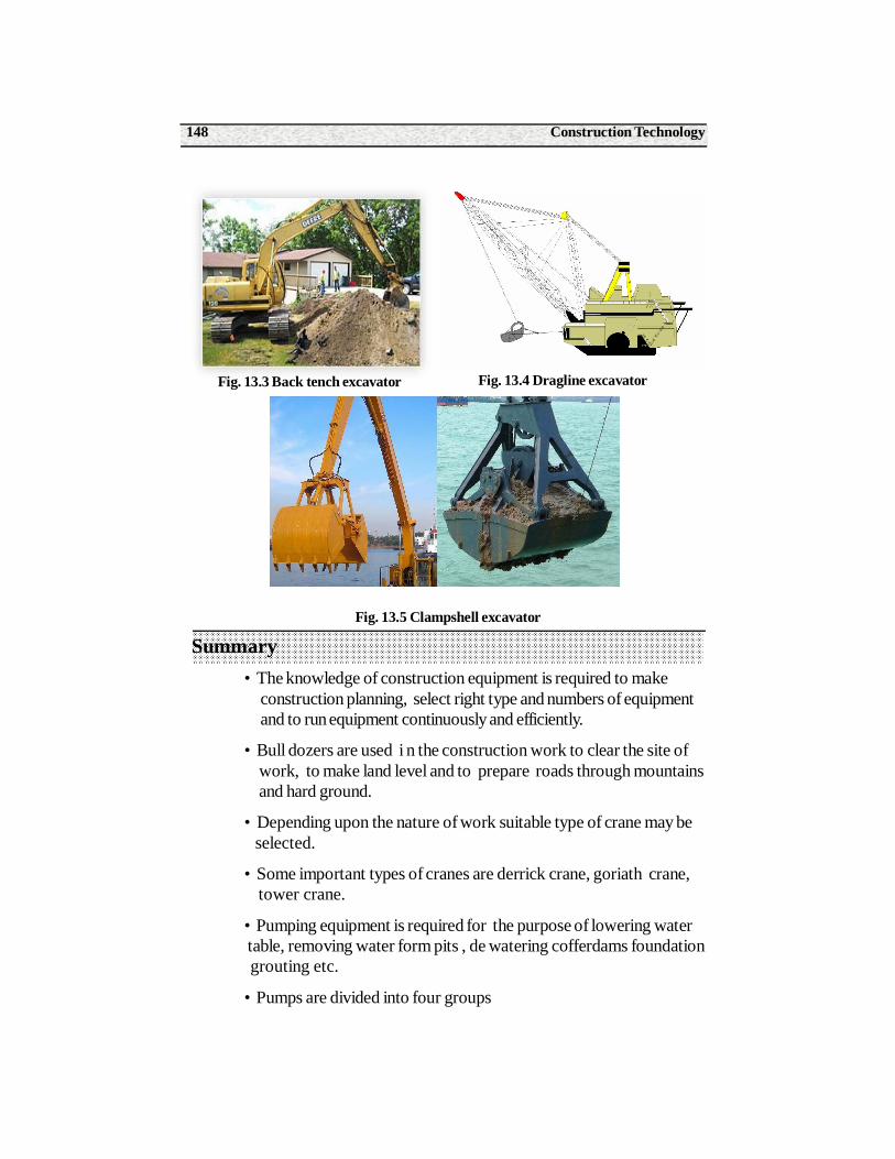
Construction Technology148
Fig. 13.5 Clampshell excavator
Summary• The knowledge of construction equipment is required to make
construction planning, select right type and numbers of equipmentand to run equipment continuously and efficiently.
• Bull dozers are used i n the construction work to clear the site ofwork, to make land level and to prepare roads through mountainsand hard ground.
• Depending upon the nature of work suitable type of crane may be selected.
• Some important types of cranes are derrick crane, goriath crane, tower crane.
• Pumping equipment is required for the purpose of lowering water table, removing water form pits , de watering cofferdams foundation grouting etc.
• Pumps are divided into four groups
Fig. 13.4 Dragline excavatorFig. 13.3 Back tench excavator
149Paper - I Construction Practice
1. Air lift pumps
2. Centrifugal pumps
3. Displacement pumps
4. Miscellaneous pumps
• Excavator is used for moving dead weight weight of earth in a vertical plane.
• Excavator may be mounted on crawler wheels or trucks
• Concrete mixers are the following types
(a) Tilting drum mixer
(b) Non-Tilting mixer
(c) Continuous mixer
• Pulley blocks are used to change the direction of ropes and to raise greater loads with less effort.
• A winch is a mechanism in the shape of a cylinder or drum over which rope or chain is wound.
Short Answer Type Questions1. List out various types of construction equipment.
2. Write the purposes of bulldozer
3. Write the use of Roller.
4. Mention of types of cranes.
5. Write the types of cranes.
6. How the pumps are classified..
7. What is the use of excavator ?
8. Write the purposes of pulley blocks.
9. Explain winches.
Long Answer Type Questions1. How the construction equipment are classified ?
2. Write short notes on (a) Crains (b) Excavators..
Construction Technology150
3. Write short notes on (a) Concrete mixers (b) Pumps
4. Write short notes on (a) Concrete mixers (b) Cranes.
7. Write about concrete mixers.
On the Job Training
1. Students should visit the sites construction work.
2. Observe different equipment which are used for construction work.
3. Maintain the records and write the function of each equipment .