Embed Size (px)
Citation preview

Invacare Celt Plus Chair
Maintenance andSpares Parts Manual

11/03Prelims ii
CELT PLUS
Contents Page
Chapter 1 Introduction
Introduction ..................................................................................................... 1.3
Policy ................................................................................................................ 1.5
Technical Details ............................................................................................. 1.5
Types ................................................................................................................ 1.5
Chapter 2 Maintenance
Scope ............................................................................................................... 2.3
Inspection ........................................................................................................ 2.5
Tools ................................................................................................................. 2.5
Removing/Replacing Backrest Canvas ......................................................... 2.7
Removing/Replacing An Armrest Assembly .............................................. 2.11
Removing/Replacing Main Wheel Assemblies ........................................... 2.15
Removing/Replacing A Brake Assembly .................................................... 2.21
Removing/Replacing A Castor Wheel Assembly ....................................... 2.23
Removing/Replacing A Swing/Detachable Footrest Assembly ............... 2.25
Removing/Replacing Seat Canvas .............................................................. 2.27
Chapter 3 Illustrated Parts Catalogue
General ............................................................................................................. 3.3
Ordering Information ...................................................................................... 3.3
CELT Wheelchair Assembly .......................................................................... 3.5
Fixed and Folding Backrest Assemblies ...................................................... 3.7
Reclining Backrest Assembly ...................................................................... 3.11
Full Armrest Assemblies with Standard and Contoured Armpad ........... 3.15
Adjustable Armrest and Sports Armrest Assemblies ............................... 3.17
Main Wheel Assemblies................................................................................ 3.19
Brake Assembly ............................................................................................ 3.23
Castor Wheel Assemblies ............................................................................ 3.25
Swing/Detachable Footrest Assemblies ..................................................... 3.27
Seat Assembly .............................................................................................. 3.33
Optional Extras - Set Back Adaptor ............................................................ 3.37
Optional Extras - Seat to Ground Seat Canvas .......................................... 3.39
Optional Extras - Headrest ........................................................................... 3.41

Page 1.111/03
INTRODUCTION
Chapter 1
Introduction

Page 1.2 11/03
CELT PLUS
Figure 1.0 CELT Wheelchair with Transit Wheels

Page 1.311/03
INTRODUCTION
Introduction
1 This manual provides basic details to enable the CELT Wheelchair to be maintained. It is not intended to bea comprehensive maintenance guide/policy, but is intended for use by competent personnel to enable thechair to be adequately maintained.
2 The manual is split into the following chapters:
Chapter 2 Detailing assemblies that are maintainable and the relevant procedures.
Chapter 3 Detailing parts that are available to enable the maintenance in Chapter 2 to be complied with.
3 For Customer Service enquires, repairs, servicing and spares, contact INVACARE Ltd. at the address belowand quote all the details as indicated in paragraphs 6 and 7.
4 INVACARE Ltd.
South Road
Bridgend Industrial Estate
Bridgend
Mid-Glamorgan
CF31 3PY
Tel No: 01656 647327
Fax No: 01656 649016
5 Quote the following details at all times:
5.1 Part Number
5.2 Description
5.3 Quantity required
6 For certain orders the following should also be quoted:
6.1 Serial or batch number
6.2 End user

Page 1.4 11/03
CELT PLUS
Figure 1.0 CELT Wheelchair with Self Propelling Wheels

Page 1.511/03
INTRODUCTION
Policy
7 INVACARE Ltd. repair policy is as follows:
Repairs to ANY component other than those detailed in Chapter 2 are not covered. Repairs to ANY metalwork is not generally permitted without express permission of INVACARE Ltd. ALL fasteners i.e. bolts,Nyloc nuts, and any fastener showing damage MUST be renewed.
Failure to comply with the above absolves INVACARE Ltd. of liability.
☞ Note: Certain components will require removal to carry out maintenance. With the exception offasteners, these components should be refitted.
Technical Details
9 The following data applies to the CELT.
9.1 Available seat widths:
13" to 19" increments.
9.2 Chair depth available (adjusted using a spigot tube):
15", 16" and 17" (other sizes on application).
9.3 Seat to ground height:
19" (standard),17" and 21".
9.4 Wheel types available:
315mm diameter (Transit) and 20", 22" and 24" Self Propelling (Standard and QR).
9.5 Maximum user weight:
20 stone (127 kg), transit and pneumatic self propelling wheel.18 stone (114.5 kg), solid self propelling wheel.
9.6 Backrest type:
Fixed 3°, 10°, 15° and 20°. Other options are folding and reclining.
9.7 Chair finish:
Polyester powdered coat (Black).
9.8 Transit weight of chair:
Approximately 17kgs (dependant on configuration and seat size).
Types
Options
10 The chair is available in various user defined optional types. For further details refer toINVACARE Ltd. for details and acceptable combinations.

Page 1.6 11/03
CELT PLUS
LEFT BLANK INTENTIONALLY

11/03 Page 2.1
MAINTENANCE
Chapter 2
Maintenance

Page 2.2 11/03
CELT PLUS
Figure 2.0.1 General Arrangement of Chair
1 Backrest 5 Castor wheel assembly2 Armrest assembly 6 Swing/detachable footrest3 Rear wheels 7 Seat4 Brake assembly
1
6
7
2
4 3
5

11/03 Page 2.3
MAINTENANCE
Scope
1 This chapter details the removal and/or replacement procedures required for the following assemblies and/oritems. It is not intended to be a strict policy of maintenance but should be used as a guide only.
2 The assemblies covered (refer to Fig 2.0) are as follows:
Section Assembly Page
2.1 Backrest Canvas/Pushhandles 2.72.2 Armrest Assemblies 2.112.3 Rear Wheel Assemblies 2.152.4 Brake Assembly 2.212.5 Castor Wheel Assemblies 2.232.6 Swing/Detachable Footrest Assemblies 2.252.7 Seat Canvas and Chassis 2.27
3 For the tools required refer to the list of tools detailed in paragraph 12. Any special tooling and/or torquerequirements will be referred to within the relevant text.
4 General engineering practices and safe working practices must be adhered to at all times.
5 For further information on the assemblies contained within this chapter, contact Customer Services,INVACARE Ltd., (refer to address in chapter 1) quoting the following details:
5.1 Part Number
5.2 Description
5.3 Quantity required
6 For certain orders the following should also be quoted:
6.1 Serial or batch number
6.2 End user
7 For any ordering or spares procurement, contact INVACARE Ltd., (refer to address in Chapter1) quoting thedetails in paragraphs 5 and 6.

Page 2.4 11/03
CELT PLUSCHAPTER 2.0
Figure 2.0.2 General Arrangement of Chair
1 Backrest 5 Castor wheel assembly2 Armrest assembly 6 Swing/detachable footrest3 Rear wheels 7 Seat4 Brake assembly
1
6
7
2
4 3
5

11/03 Page 2.5
MAINTENANCE
Inspection
8 In general, a weekly visual check will meet all the inspection requirements.
9 Ensure that the following are checked:
9.1 Fabric is undamaged and has no signs of sagging.
9.2 The footrest is correctly fitted and latched.
9.3 Both armrests are securely fitted in place.
9.4 Brake mechanism operates freely and, when locked, the chair does not move.
9.5 Footplates and heel slings are undamaged and are correctly fitted.
9.6 Tyres are in good order and the wheels are not damaged.
9.7 If stabilisers are fitted, they are firmly locked in place.
9.8 Check that quick release spindle releases and locks correctly.
10 Check the finish of the chair for any damage.
☞ Note: Some finishes are unique to the chair. Check with INVACARE Ltd. for details.
11 Check that all bungs/plugs and handgrips are fitted and undamaged.
Tools
12 The following list details the basic tools required to carry out the maintenance procedures detailed in the followingsub-chapters.
12.1 Pliers
12.2 Drills (Metric and Imperial)
12.3 Spanners (Metric and Imperial)
12.4 Pozidriv screwdriver
12.5 Thin flat bladed screwdriver
12.6 Adjustable spanner
12.7 Torque wrench (20 to 40 lbf.ft rating)
12.8 Set of Allen keys (Metric and Imperial)
12.9 Protected jaw grips
12.10 Nylon mallet
12.11 Pop rivet gun
☞ Note: The above list is not exhaustive.

Page 2.6 11/03
CELT PLUS
Figure 2.1.1 Folding Backrest Assembly
1 Backrest canvas 6 Plunger knob2 Handgrips 7 Plunger3 Push handle L/H 8 Hex head bolt4 Cup washer 9 Nyloc nut5 Pozi head screw 10 Washer
11 Lower half back frame tube
3
1
2
9
6
7
10
8
11
4
5

11/03 Page 2.7
MAINTENANCE
2.1 Removing/Replacing Backrest Canvas/Pushhandles
General
1 Check the (Fig 2.1.1) Backrest Canvas (1) and Push Handle (3) for any defects, (refer to paragraphs 4 and5). If any defects are observed then refer to paragraphs 6 to 10 for maintenance.
2 Ensure that the push handle locks securely and that the locking mechanism functions correctly.
Tools
3 Refer to the tool list at the beginning of this Chapter.
Inspection
4 Inspect on a weekly basis for the following:
4.1 No signs of sagging, stretching or excessive wear in the Canvas (1).
4.2 No evidence of fraying, especially around the fastener points.
4.3 Pozidriv Head Screws (5) not missing and are tight.
4.4 Cup Washers (4) not missing and are tight.
5 Inspect the locking mechanism for the following:
5.1 Levers are not deformed or damaged.
5.2 Locks safely when the Push Handle (3) is in the upright position.
5.3 Not excessively stiff to operate (action should be smooth and positive).
Removal of the backrest canvas/pushhandles
6 To remove the Foldable Backrest (Fig 2.1.1) Canvas (1) proceed as follows:
6.1 Release the Plunger Knob (6) and fold the Push Handle (3) down.
6.2 Unscrew and remove the four Pozidriv Head Screws (5) and Cup Washers (4).
6.3 Unscrew and remove the two Bolts (8), Nyloc Nuts (9) and Plain Washers (10).
6.4 Unscrew and remove the two Plunger Knobs (6).
6.5 Slide the Backrest Canvas (1) off the Push Handle (3).
6.6 Slide the Backrest Canvas (1) off the lower half of the Back Frame (11).
7 To remove the canvas from the fixed backrest (Fig 2.1.2) proceed as follows:
7.1 Release the plunger operated lock in both rear vertical frame tubes and pull the complete backrestout of the chassis.
7.2 Remove the pozihead screws (4) and washers (3) from both sides of the Backrest Tube (5) andslide the canvas (6) off the backrest frame.

Page 2.8 11/03
CELT PLUS
1 Neoprene grip 5 Pozihead screw2 Push handle bar 6 Canvas3 Back rest frame 7 Spring clip4 Washer 8 Screw
Figure 2.1.3 Reclining Backrest
Figure 2.1.2 Fixed Backrest
1 Neoprene grip 4 Pozihead screw2 Push handle bar 5 Fixed backrest tube3 Washer 6 Canvas
1
2
3
5
6
4
3
1
72
8
4
3
6
5

11/03 Page 2.9
MAINTENANCE
8 To remove the canvas from the reclining backrest (Fig 2.1.3) proceed as follows:
8.1 Remove the Push Handle Bar (2) from the Backrest Frame (3) by depressing the Spring Clips (7).
☞ Note: It may be necessary to use pliers or a similar tool to extract the Spring Clips.
8.2 Remove the Pozi head screws (5) and washers (4) from the Backrest Frame tube (3).
8.3 Release the Canvas (6) by pulling apart the Velcro seal from the canvas.
8.4 Remove the canvas by sliding it off the Backrest Frame.
Replacing the backrest canvas
9 To replace the backrest canvas is the reverse of the removal, however ensure the following:
9.1 New Nyloc nuts are fitted.
9.2 The securing points are undamaged.
9.3 New cup washers are fitted as required.
9.4 That the backrest canvas is stretched evenly and is taut.
9.5 New Spring Clips are fitted in the Push Handle bar as required.

Page 2.10 11/03
CELT PLUS
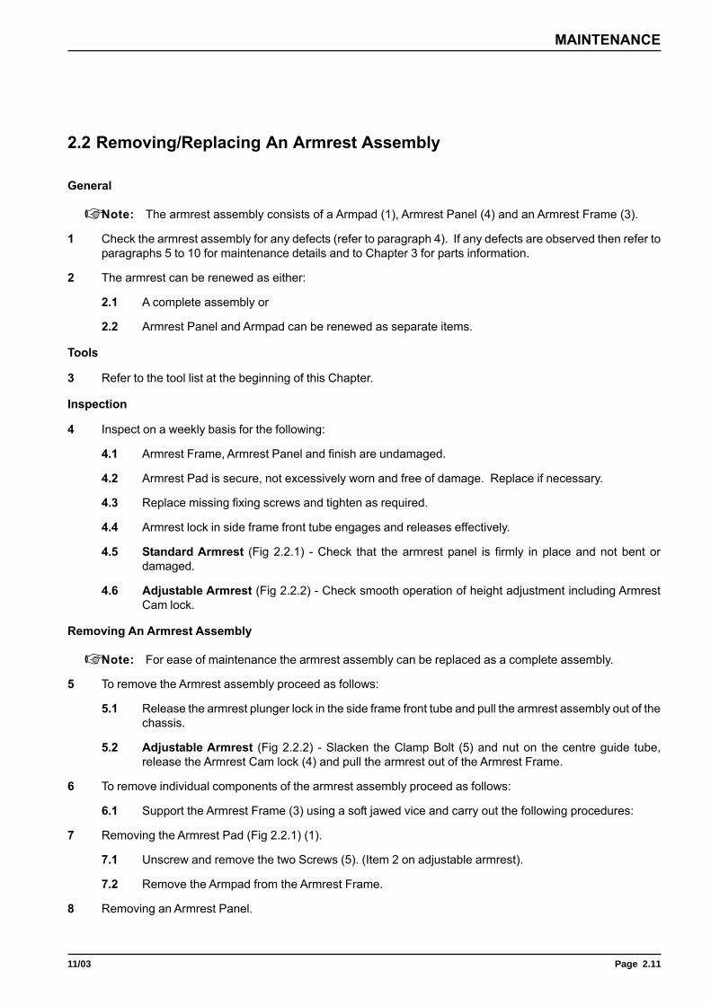
Figure 2.2.1 Armrest Assembly
5
6
2
3
4
1
1 Armpad2 Sealing plug3 Armrest frame4 Armrest panel5 Countersunk screw6 Self tapping screw
11/03 Page 2.11
MAINTENANCE
2.2 Removing/Replacing An Armrest Assembly
General
☞ Note: The armrest assembly consists of a Armpad (1), Armrest Panel (4) and an Armrest Frame (3).
1 Check the armrest assembly for any defects (refer to paragraph 4). If any defects are observed then refer toparagraphs 5 to 10 for maintenance details and to Chapter 3 for parts information.
2 The armrest can be renewed as either:
2.1 A complete assembly or
2.2 Armrest Panel and Armpad can be renewed as separate items.
Tools
3 Refer to the tool list at the beginning of this Chapter.
Inspection
4 Inspect on a weekly basis for the following:
4.1 Armrest Frame, Armrest Panel and finish are undamaged.
4.2 Armrest Pad is secure, not excessively worn and free of damage. Replace if necessary.
4.3 Replace missing fixing screws and tighten as required.
4.4 Armrest lock in side frame front tube engages and releases effectively.
4.5 Standard Armrest (Fig 2.2.1) - Check that the armrest panel is firmly in place and not bent ordamaged.
4.6 Adjustable Armrest (Fig 2.2.2) - Check smooth operation of height adjustment including ArmrestCam lock.
Removing An Armrest Assembly
☞ Note: For ease of maintenance the armrest assembly can be replaced as a complete assembly.
5 To remove the Armrest assembly proceed as follows:
5.1 Release the armrest plunger lock in the side frame front tube and pull the armrest assembly out of thechassis.
5.2 Adjustable Armrest (Fig 2.2.2) - Slacken the Clamp Bolt (5) and nut on the centre guide tube,release the Armrest Cam lock (4) and pull the armrest out of the Armrest Frame.
6 To remove individual components of the armrest assembly proceed as follows:
6.1 Support the Armrest Frame (3) using a soft jawed vice and carry out the following procedures:
7 Removing the Armrest Pad (Fig 2.2.1) (1).
7.1 Unscrew and remove the two Screws (5). (Item 2 on adjustable armrest).
7.2 Remove the Armpad from the Armrest Frame.
8 Removing an Armrest Panel.
Page 2.12 11/03
CELT PLUS
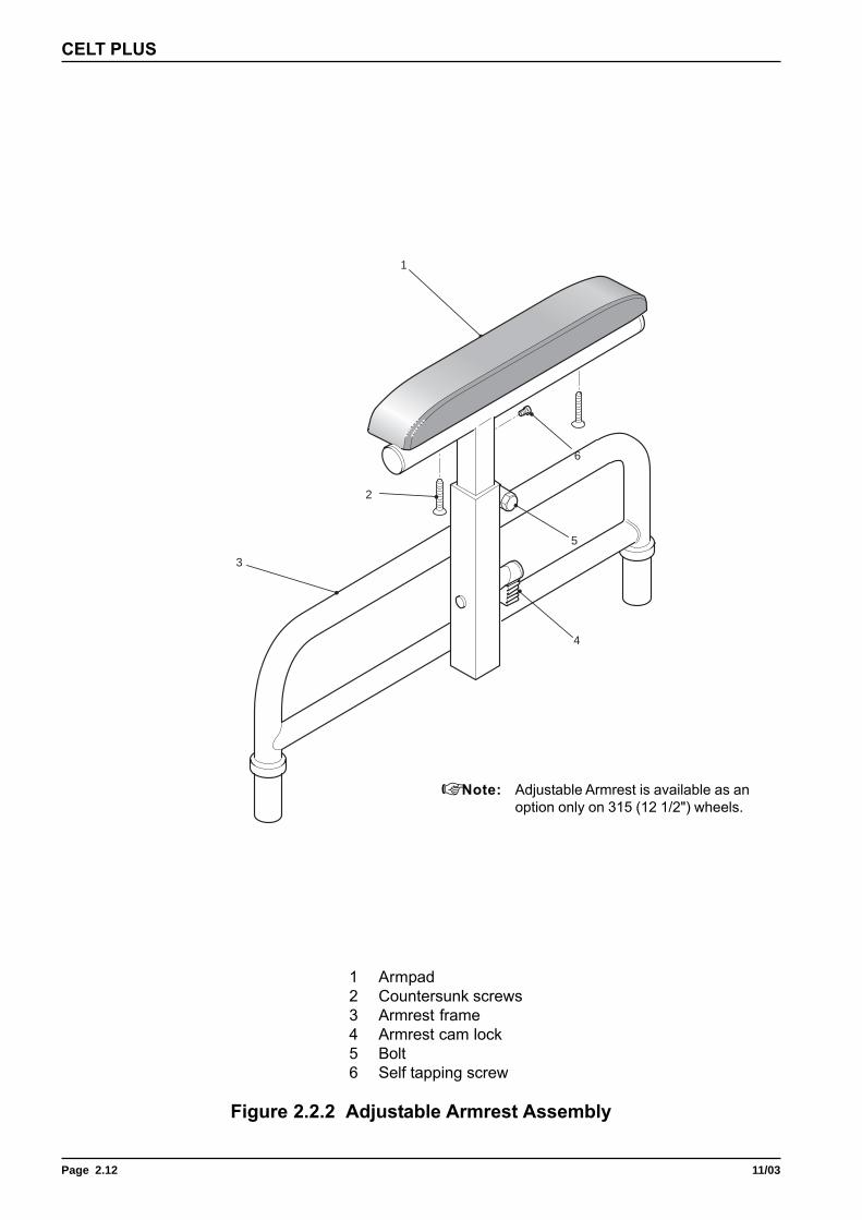
Figure 2.2.2 Adjustable Armrest Assembly
1 Armpad2 Countersunk screws3 Armrest frame4 Armrest cam lock5 Bolt6 Self tapping screw
1
3
6
5
4
2
☞ Note: Adjustable Armrest is available as anoption only on 315 (12 1/2") wheels.
11/03 Page 2.13
MAINTENANCE
8.1 Unscrew self tapping screw (6) from front of armrest.
8.2 Unclip the Armrest Panel (5) from the Armrest Frame (3) by pushing it horizontally in the direction ofthe front of the chair and remove it.
Replacing Armrest Components
9 To replace the Armrest assembly or any of the components of the Armrest assembly is the reverse of theremoval; however ensure the following:
9.1 The Armrest Panel is flush fitting to the Frame.
9.2 Sealing Plugs are undamaged when replaced.

Page 2.14 11/03
CELT PLUS
Figure 2.3.1 Rear Wheel Assembly
1 Wheel locknut 3 Rear wheel2 Washer
2
1
3

11/03 Page 2.15
MAINTENANCE
2.3.1 Removing/Replacing Rear Transit Wheel Assemblies
General
☞ Note: This chair can be fitted with the following wheel types:
(a) Transit style, 315 mm solid or pneumatic.
(b) A 20 in, 22 in or 24 in diameter wheel with hand rim and Quick Release (Q.R.) hub,solid or pneumatic tyres.
1 Check the wheel assembly for any defects (refer to paragraph 5). If any defects are observed then refer toparagraphs 6 to 11 for maintenance details and to Chapter 3 for parts.
2 The main wheel assembly can be renewed as a complete assembly.
Tools
3 Refer to the tool list at the beginning of this Chapter.
3.1 A torque wrench of 25 lbf.ft rating is required.
Inspection
4 Inspect on a weekly basis for the following:
4.1 Damage to either wheel or tyre.
4.2 When the wheel assembly is allowed to free wheel that no binding, grating noise orunconcentric rotation are present.
4.3 Wheel rim and spokes are undamaged.
4.4 If fitted, the hand rim is undamaged.
4.5 Excessive bearing rock.
Removing A Transit Wheel Assembly
5 To remove a transit wheel (3) (refer to Fig 2.3.1) proceed as follows:
5.1 Raise and support the chair so the damaged wheel is free of the ground.
5.2 Using a suitable size spanner grip the nut located behind the wheel hub.
5.3 Using the torque wrench, unscrew and remove the wheel locknut (1) and washer (2).
5.4 Slide the wheel (3) free from its location on the frame.
Replacing A Main Wheel Assembly
CAUTION: Apply Loctite 242 to the thread of the wheel shaft and ensure that the transit wheellocknut is tightened to a torque of 25 lbf.ft.
☞ Note: Refer to section 2.3.1 for further information on configuration details.
6 Replacing the main wheel assemblies is the reverse of the removal.

Page 2.16 11/03
CELT PLUS
Figure 2.3.2 Self-Propelling Wheel Assemblies
1 Locking nut2 Washer3 Mounting bush4 Tyre5 Hand rim6 Black nut cover7 Nut8 QR spindle9 N/A
10 N/A11 Plastic hub cap
3
2
1
10
8
11
9
6
7
4
5

11/03 Page 2.17
MAINTENANCE
2.3.2 Removing/Replacing Rear Wheel Quick Release Assemblies
General
☞ Note: This chair can be fitted with the following wheel types:
(a) Transit style, 315 mm solid or pneumatic.
(b) A 20 in, 22 in or 24 in diameter wheel with hand rim and Quick Release (Q.R.) hub,solid or pneumatic tyres.
1 Refer to section 2.3.3 for details on how to configure the chair when fitting larger 22 in or 24 in diameter wheels.
2 Check the wheel assembly for any defects (refer to paragraph 5). If any defects are observed then refer toparagraphs 6 to 11 for maintenance details and to Chapter 3 for parts.
3 The main wheel assembly can be renewed as either:
3.1 A complete assembly.
3.2 Replacement for the hand rim (20 in, 22 in or 24 in diameter wheel only).
3.3 Pneumatic or solid tyre.
Tools
4 Refer to the tool list at the beginning of this Chapter.
4.1 A torque wrench of 25 lbf.ft rating is required.
Inspection
5 Inspect on a weekly basis for the following:
5.1 Damage to either wheel or tyre.
5.2 When the wheel assembly is allowed to free wheel that no binding, grating noise, excessive bearingrock or unconcentric rotation are present.
5.3 Wheel rim and spokes are undamaged.
5.4 If fitted, the hand rim is undamaged.
5.5 Quick release hub is fully located in place and the wheel is totally secure.
Removing a 20", 22" or 24" Diameter Rear Wheel Assembly
8 To remove a QR hub fitted wheel, proceed as follows:
81 Remove the hub cap (11).
8.1 Push the inner button and slide the wheel assembly out of the locating block.
9 Prior to fitting the wheel assemblies, ensure that the location is undamaged.
Replacing A Quick Release Wheel Assembly
☞ Note: Refer to section 2.3.1 for further information on configuration details.
10 Replacing the main wheel assemblies is the reverse of the removal.

Page 2.18 11/03
CELT PLUS
Figure 2.3.3 Brake Configuration Arrangement
1 Brake Assembly 2 Self Propelling Wheel Assembly
1
2
11/03 Page 2.19
MAINTENANCE
2.3.3 Configuring The Chair For 20 in, 22 in or 24 in Wheel And BrakeAssembly
General
1 The CELT can be configured to accept the following set-up:
1.1 20 in, 22 in or 24 in Quick Release wheel configured for self-propelling.
☞ Note: For parts identification refer to Chapter 3.
Configuring
2 To configure the chair, the above information is required (check the order).
3 The following procedure is for guidance only:
3.1 Select the relevant sized wheel.
3.2 Fit the wheel into the correct locking hole on the chassis frame.
☞ Note: All locations are given when looking from the swing/detachable footrest assembly end.
4 Fit the brake assembly (1) into place on the chassis frame under the seat canvas.
5 Using the adjusting bar correctly position the stop bar on the brake to a suitable position so that when thebrake is operated the wheel locks.
6 Repeat paragraphs (3 to 5) for the other side
☞ Note: 22 in wheel in R.W.S.B. position is bolt on not quick release.

Page 2.20 11/03
CELT PLUS
Figure 2.4 Brake Assembly
1 Brake assembly 3 Washer2 Hexagon bolt 4 Nut
2
3
1
3
4

11/03 Page 2.21
MAINTENANCE
2.4 Removing/Replacing A Brake Assembly
General
☞ Note: The brake assembly is handed, ensure that if both assemblies are removed, the correct assemblyis fitted to the correct side.
1 Check the brake assembly for any defects (refer to paragraph 4). If any defects are observed then refer toparagraphs 5 to 6 for maintenance details and to Chapter 3 for parts information.
2 It is not intended that any other part is maintainable.
Tools
3 Refer to the tool list at the beginning of this Chapter.
Inspection
4 Check the following daily:
4.1 Brake assembly fully locks and the chair is unable to move either on level ground or on a slope.
4.2 Brake action is positive and is not stiff or sluggish.
☞ Note: It may be possible to rectify excessive sluggishness in the mechanism by tightening theToggle Joint nuts.
Removing A Brake Assembly
☞ Note: For ease of maintenance the Brake assembly can be removed as a complete assembly.
5 To remove the Brake assembly proceed as follows:
5.1 Note down the position of the Brake assembly on the chassis. This will be required in order to replacethe Brake assembly in exactly the same position.
5.2 Ensure that Brake assembly is in the unlocked position.
5.3 Support the Brake assembly (1) and using spanners of suitable size unscrew the Hex Head bolts (2)securing the Brake assembly to the chassis side frame.
5.4 Remove the Brake assembly from its location.
☞ Note: In the event of faults or damage to any part of the Brake assembly, the complete assemblyshould be removed and replaced.
Replacing A Brake Assembly
6 To replace a brake assembly is the reverse of the removal.
Page 2.22 11/03
CELT PLUS
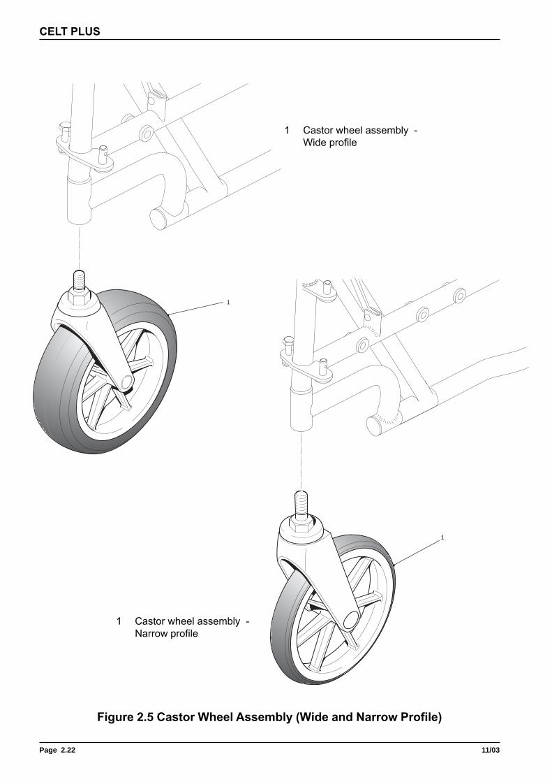
1 Castor wheel assembly -Narrow profile
1
Figure 2.5 Castor Wheel Assembly (Wide and Narrow Profile)
1
1 Castor wheel assembly -Wide profile

11/03 Page 2.23
MAINTENANCE
2.5 Removing/Replacing A Castor Wheel Assembly
General
1 Check the castor wheel assembly for any defects (refer to paragraph 4). If any defects are observed thenrefer to paragraphs 5 to 7 for maintenance details and to Chapter 3 for parts information.
2 It is not intended that any other part is maintainable.
Tools
3 Refer to the tool list at the beginning of this Chapter.
Inspection
4 Check the following:
4.1 Castor Fork is not distorted and is undamaged.
4.2 Tyre is not cracked or excessively worn.
4.3 Castor Wheel rotates freely when lifted clear of the ground and spun.
4.4 Alternatively, Pivot the castor Fork through a 90 degree arc, so that it is in a horizontal position. Allowthe Fork and Wheel to drop. The assembly should swing 2 to 3 times and come to rest in a straightdownward position.
4.5 The tyre is firmly fitted and concentric within the rim.
☞ Note: In the event of failure in any of the above, the assembly must be removed and replaced.
4.6 Castor assembly is firmly located and secure.
Removing A Castor Wheel Assembly
5 To remove the castor wheel assembly proceed as follows:
5.1 Raise and support the front end of the chair. This can be achieved by tipping the chair back.
5.2 Using an adjustable spanner unscrew the Fork nut until the castor assembly releases from its location.
5.3 Remove the castor wheel assembly.
5.4 Check that the castor wheel location is undamaged and clean.
Replacing A Castor Wheel Assembly
Caution: Apply Loctite 242 or equivalent to the thread of the castor wheel shaft and ensure thatthe castor wheel is tightened using the Fork nut to a torque of 30 lbf.ft.
6 Replacing the castor wheel assembly is the reverse of the removal; ensure the following:
6.1 It is firmly located, secure and undamaged.
6.2 Freely rotates through 360 degrees. Refer to paragraph 4.3.
7 Once correctly fitted, remove the support (if used) and allow the chair to sit on all four wheels. Check that itfunctions correctly.

Page 2.24 11/03
CELT PLUS
1 Latching plate2 Nut3 Washer4 Shim5 Spring6 Shouldered bolt7 Foot plate8 Foot plate stem tube9 Foot plate front/rear tube10 Clamp tube sub-assembly11 Swinger tube
1 Latching plate2 Nut3 Washer4 Shim5 Spring6 Shouldered bolt7 Heel sling assembly8 Foot plate9 Plastic cap10 Stem tube assembly11 Swinger tube
Figure 2.6 Swing/Detachable Footrest Assembly
(a) Standard Footrest
(b) Optional Footrest
1 2
3
4
5
6
11
9
10 7
8
10
8
7
9
4
5
6
1 2
311

11/03 Page 2.25
MAINTENANCE
2.6 Removing/Replacing A Swing/Detachable Footrest Assembly
General
1 Check the swing/detachable footrest assembly (Fig 2.6) for any defects (refer to paragraph 3). If any defectsare observed then refer to paragraphs 5 to 9 for maintenance details and to Chapter 3 for parts information.
Tools
2 Refer to the tool list at the beginning of this Chapter.
Inspection
3 Check the following:
3.1 Footplate (Fig 2.6 (a)) (8) is undamaged, fitted securely to the Stem Tube assembly (10), swivels upand down smoothly and is effectively supported in horizontal.
3.2 Heel Sling assembly (7) is undamaged and securely fastened to the Footplate (8).
3.3 Latching mechanism (1) functions correctly and the footrest assembly locks securely in place.
3.4 Stem Tube assembly (10) is undamaged.
3.5 Locating holes and Lugs are free from damage.
4 Any of the above defects or other damage will require the assembly to be repaired or replaced.
Removing A Swing/Detachable Footrest Assembly
5 To remove the swing/detachable footrest assembly proceed as follows:
5.1 Operate the latching mechanism and allow the footrest assembly to rotate away from the frame.
5.2 Lift the swing/detachable footrest assembly free of the locating lugs.
6 To remove a footplate (8), proceed as follows:
6.1 Remove the Plastic Cap (9), prise it loose with a screwdriver if necessary.
6.2 Slide the Footplate (8) free of the Stem Tube assembly (10).
7 To remove a Heel Sling assembly (7), proceed as follows:
☞ Note: The heel sling assembly has flats on the two supports which can be used to enable the heel slingassembly to be removed.
7.1 Support the adjustable Stem Tube (10) in a soft jawed vice with the Footplate (8) upside down.
7.2 Support the Heel Sling assembly (7)
7.3 Unscrew and remove the two Nyloc nuts and washers located under the footplate.
7.4 Remove the Heel Sling assembly (7).
Replacing A Swing/Detachable Footrest Assembly
8 Replacing any component previously mentioned is the reverse of the removal, refer to paragraphs (5) to (7),
☞ Note: Use new bolts and nuts, plastic cap, etc., if the removed fasteners show sign of excessive wear ordamage to threads.

Page 2.26 11/03
CELT PLUS
Figure 2.7 Seat Canvas Assembly
1 Seat canvas 6 Dished washer2 Screw 7 Stabiliser3 Washer 8 Nyloc nut4 Side frame 9 Plastic cap5 Hexagonal head bolt 10 Reinforcing bar
5
6
7
6
8
10
9
1
2
3
4

11/03 Page 2.27
MAINTENANCE
2.7 Removing/Replacing A Seat Canvas
General
1 Check the Seat Canvas (1) for any defects (refer to paragraph 3). If any defects are observed then refer toparagraphs 5 to 6 for maintenance details and to Chapter 3 for parts information.
Tools
2 Refer to the tool list at the beginning of this Chapter.
Inspection
3 Check for the following:
3.1 Damage to Seat Canvas (1).
3.2 Sagging.
3.3 Reinforcing Bar (10) missing and/or damaged.
4 Generally replace and/or tighten any Screws or Cup Washers that are missing/damaged or are loose.
Removing The Seat Canvas
5 To remove the Seat Canvas (1) proceed as follows:
5.1 Unscrew and remove the eight countersunk screws (2) and Cup Washers (3).
5.2 Remove the two Reinforcing Bars (10) located inside the seat canvas.
5.3 Remove the Seat Canvas (1).
Replacing The Seat Canvas
☞ Note: Check for the correct seat canvas size.
6 Replacing the Seat Canvas (1) is the reverse of the removal, refer to Chapter 3 for parts information.
7 Ensure that the Seat Canvas (1) is correct for the size of chair being repaired. If a new size is being fitted i.e.from 16 in to 17 in deep then check the following:
7.1 Correct size reinforcing bars (10) are used.
7.2 Seat adjustment tubes have been correctly adjusted.

Page 2.28 11/03
CELT PLUS
LEFT BLANK INTENTIONALLY

Page 3.111/03
PARTS LIST
Item Part Number Description
Chapter 3
Illustrated Parts Catalogue

Page 3.2 11/03
CELT PLUS
LEFT BLANK INTENTIONALLY
Page 3.311/03
PARTS LIST
Item Part Number Description
General
1 This chapter has been split into sections which correspond to the sections in chapter 2.
2 Refer to the general assembly Figure 3.0 for location of the assemblies covered by the followingsections:
Section Assembly Pages
3.1 Backrest Assemblies 6-13
3.2 Armrest Assemblies 14-17
3.3 Rear Wheel Assemblies 18-21
3.4 Brake Assembly 22-23
3.5 Castor Wheel Assemblies 24-25
3.6 Swing/Detachable Footrest Assemblies 26-29
3.7 Seat Assembly 30-33
3.8 Optional Extras 34-39
3 Each section contains the following information in table format:
3.1 Fig/Item reference number
3.2 Part Number
3.3 Description
3.4 Qty fitted
� Note:The following references are used:
A/R Denote fasteners etc where the fastener, such as nuts are common to the chair.
NI When an assembly or component is not illustrated.
Ordering Information
4 To order components or parts information from the relevant address, refer to Chapter 1. Alwaysquote the following:
4.1 Part Number
4.2 Description
4.3 Quantity required
5 For certain orders the following should also be quoted
5.1 Serial or batch number
5.2 End user

Page 3.4 11/03
CELT PLUS
Figure 3.0 General Arrangement of CELT Wheelchair
Page 3.511/03
PARTS LIST
Item Part Number Description
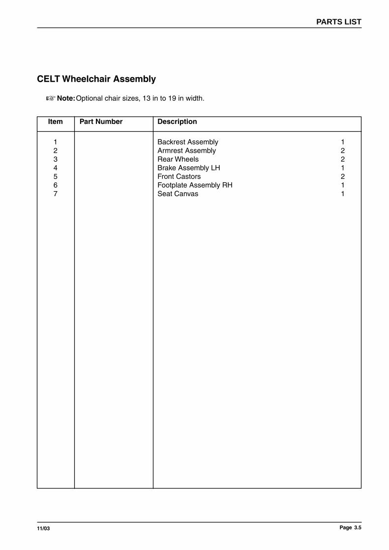
CELT Wheelchair Assembly
� Note:Optional chair sizes, 13 in to 19 in width.
1 Backrest Assembly 12 Armrest Assembly 23 Rear Wheels 24 Brake Assembly LH 15 Front Castors 26 Footplate Assembly RH 17 Seat Canvas 1
Page 3.6 11/03
CELT PLUS
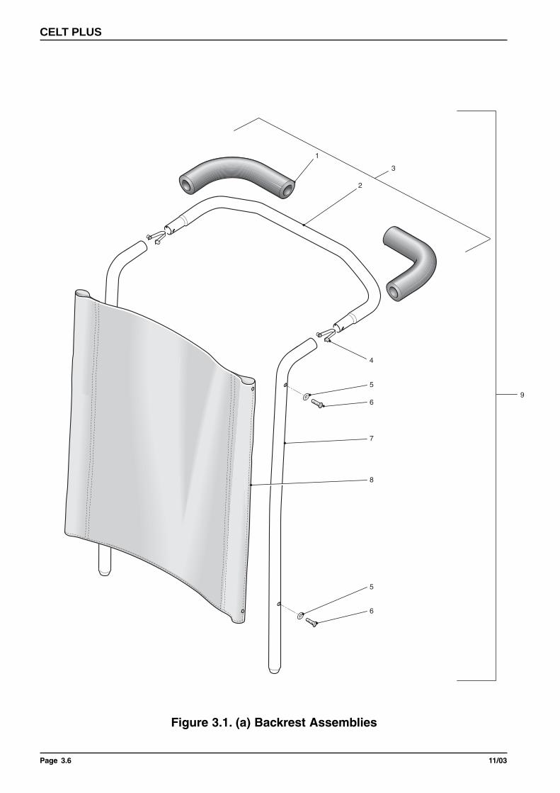
Figure 3.1. (a) Backrest Assemblies
1
2
5
7
8
6
4
3
5
6
9

Page 3.711/03
PARTS LIST
Item Part Number Description
Fixed Backrest Assembly
� Note:Optional chair sizes, 13 in to 19 in width.
Fixed Backrest Assembly
3 3013/33 13" Push Bar Assembly - Kit includes items 1,2 & 43015/33 15" Push Bar Assembly - Kit includes items 1,2 & 43016/33 16" Push Bar Assembly - Kit includes items 1,2 & 43017/33 17" Push Bar Assembly - Kit includes items 1,2 & 43018/33 18" Push Bar Assembly - Kit includes items 1,2 & 43018/34 19" Push Bar Assembly - Kit includes items 1,2 & 4
5 D20101 M5 x 20 Taptite Screw6 5009551 Upholstery Plastic Washer
7 3017/58/08 Fixed Backrest Tube Assembly (Pairs)3017/58/15 Fixed Backrest Tube Assembly (Pairs)3017/58/20 Fixed Backrest Tube Assembly (Pairs)3017/58/25 Fixed Backrest Tube Assembly (Pairs)
8 1415290 Fixed Backrest Canvas 330 (13") Wide1415291 Fixed Backrest Canvas 381 (15") Wide1415292 Fixed Backrest Canvas 406 (16") Wide1415293 Fixed Backrest Canvas 432 (17") Wide1415294 Fixed Backrest Canvas 457 (18") Wide1415295 Fixed Backrest Canvas 483 (19") Wide
9 1422265 Fixed Backrest Assembly Complete 330 (13") Wide1422266 Fixed Backrest Assembly Complete 381 (15") Wide1422267 Fixed Backrest Assembly Complete 406 (16") Wide1422268 Fixed Backrest Assembly Complete 432 (17") Wide1422269 Fixed Backrest Assembly Complete 457 (18") Wide1422270 Fixed Backrest Assembly Complete 483 (19") Wide

Page 3.8 11/03
CELT PLUS
Figure 3.1. (b) Backrest Assemblies

Page 3.911/03
PARTS LIST
Item Part Number Description
Folding Backrest Assembly
� Note:Optional chair sizes, 13 in to 19 in width.
Folding Backrest Assembly
1 1415284 Folding Backrest Canvas 330 (13") Wide1415285 Folding Backrest Canvas 381 (15") Wide1415286 Folding Backrest Canvas 406 (16") Wide1415287 Folding Backrest Canvas 432 (17") Wide1415288 Folding Backrest Canvas 457 (18") Wide1415289 Folding Backrest Canvas 483 (19") Wide
2 L10009 Handgrip4 5009551 Upholstery Plastic Washer5 D20101 M5 x 20 Taptite Screw
12 3017/49/08 8Deg Folding Backrest (Pairs)3017/49/15 15Deg Folding Backrest (Pairs)3017/49/20 20Deg Folding Backrest (Pairs)
Item 12 Includes 2,3,6,7,8,9,10, & 11

Page 3.10 11/03
CELT PLUS
Figure 3.1. (c) Backrest Extension

Page 3.1111/03
PARTS LIST
Item Part Number Description
Backrest Extension Assembly
� Note: Optional chair sizes, 13 in to 19 in width.
Backrest Extensions
1415314 B/rest Ext Assy 330 (13") Wide 230 H1415315 B/rest Ext Assy 381 (15") Wide 230 H1415316 B/rest Ext Assy 406 (16") Wide 230 H1415317 B/rest Ext Assy 432 (17") Wide 230 H1415318 B/rest Ext Assy 457 (18") Wide 230 H1415319 B/rest Ext Assy 483 (19") Wide 230 H

Page 3.12 11/03
CELT PLUS
Figure 3.1 (d) Reclining Backrest Assembly
1
2
7
15
24
26
27
25
8
16
13
23
9
1722
4
3
10
12
1821
20 19
5
14
11
6
28
28
29

Page 3.1311/03
PARTS LIST
Item Part Number Description
Reclining Backrest Assembly
Reclining Backrest Assembly Std 17" High
29 3017/TA Reclining Backrest Tube Assembly RH3017/TF Reclining Backrest Tube Assembly LH
28 3013/33 13" Push Bar Assembly - Kit includes items 1,2 & 33015/33 15" Push Bar Assembly - Kit includes items 1,2 & 33016/33 16" Push Bar Assembly - Kit includes items 1,2 & 33017/33 17" Push Bar Assembly - Kit includes items 1,2 & 33018/33 18" Push Bar Assembly - Kit includes items 1,2 & 33018/34 19" Push Bar Assembly - Kit includes items 1,2 & 3
27 1415296 Rec B/rest Canvas 330 (13””) Wide 17" H1415297 Rec B/rest Canvas 381 (15””) Wide 17" H1415298 Rec B/rest Canvas 406 (16””) Wide 17" H1415299 Rec B/rest Canvas 432 (17””) Wide 17" H1415300 Rec B/rest Canvas 457 (18””) Wide 17" H1415301 Rec B/rest Canvas 483 (19””) Wide 17" H
11 3017/RA/01 Gas Strut 400N
Reclining Backrest Assembly 21" High
NI 1415302 Rec B/rest Canvas 330 (13””) Wide 21" H1415303 Rec B/rest Canvas 381 (15””) Wide 21" H1415304 Rec B/rest Canvas 406 (16””) Wide 21" H1415305 Rec B/rest Canvas 432 (17””) Wide 21" H1415306 Rec B/rest Canvas 457 (18””) Wide 21" H1415307 Rec B/rest Canvas 483 (19””) Wide 21" H
NI 3017/FF Rec B/rest Tube Assembly RH 21"H3017/FR Rec B/rest Tube Assembly LH 21"H

Page 3.14 11/03
CELT PLUS
Figure 3.1 (e) Extended Reclining Backrest Assy
Figure 3.1 (f) Extended Fixed Backrest Assy

Page 3.1511/03
PARTS LIST
Item Part Number Description
Extended Recliner Backrest Assembly 25" and 32.5" High
1436892 25" Ext recliner b/rest assy kit RH1436893 25" Ext recliner b/rest assy kit LH1436894 32.5" Ext recliner b/rest assy kit RH1436895 32.5" Ext recliner b/rest assy kit LH
1426027 330 (13") Wide Rec B/Rest Canvas 825mm High1426028 381 (15") Wide Rec B/Rest Canvas 825mm High1426029 406 (16") Wide Rec B/Rest Canvas 825mm High1426030 432 (17") Wide Rec B/Rest Canvas 825mm High1426031 457 (18") Wide Rec B/Rest Canvas 825mm High1426032 483 (19") Wide Rec B/Rest Canvas 825mm High1426033 330 (13") Wide Rec B/Rest Canvas 625mm High1426034 381 (15") Wide Rec B/Rest Canvas 625mm High1426035 406 (16") Wide Rec B/Rest Canvas 625mm High1426036 432 (17") Wide Rec B/Rest Canvas 625mm High1426037 457 (18") Wide Rec B/Rest Canvas 625mm High1426038 483 (19") Wide Rec B/Rest Canvas 625mm High
Extended Fixed Backs 32.5" High
1436896 32.5" Ext fixed b/rest assy kit RH1436897 32.5" Ext fixed b/rest assy kit LH
1426039 330 (13") Wide Fixed B/Rest Canvas 825mm High1426040 381 (15") Wide Fixed B/Rest Canvas 825mm High1426041 406 (16") Wide Fixed B/Rest Canvas 825mm High1426042 432 (17") Wide Fixed B/Rest Canvas 825mm High1426043 457 (18") Wide Fixed B/Rest Canvas 825mm High1426044 483 (19") Wide Fixed B/Rest Canvas 825mm High
Extended Backrest Assemblies

Page 3.16 11/03
CELT PLUS
Figure 3.2 Armrest Assemblies
1
2
3
5
4
6
7
6
8
(a) Full Armrest
(b) Armrest with Contoured Armpad
1
2
3
5
4
6
7
8
9

Page 3.1711/03
PARTS LIST
Item Part Number Description
Full Armrest Assemblies with Standard and Contoured Armpads
Full Armrest With Std & Contoured Armpads
8 1416162 Full Armrest With Std Armpad RH1416163 Full Armrest With Std Armpad LH
5 3017/17/01 Plastic Panel RH3017/19/01 Plastic Panel LH
7 10"BLKPADKIT 10" Black Armpad Kit (Includes items 1,2 & 4)
Full Armrest With Contoured Armpads
8 1422210 Contoured Armrest Assy RH1422211 Contoured Armrest Assy LH
7 SKA 2304 Contoured Armpad RH (includes items1 to 5)SKA 2305 Contoured Armpad LH (includes items1 to 5)
9 3017/17/01 Plastic Panel RH3017/19/01 Plastic Panel LH

Page 3.18 11/03
CELT PLUS
Figure 3.2.c Adjustable Armrest Assembly
� Note: Adjustable Armrest is available as anoption only on 315 (12 1/2") wheels.
5
7
6
1
2
3
4
11
12
8
9
10
13
15
14

Page 3.1911/03
PARTS LIST
Item Part Number Description
Adjustable and Sports Armrest Assemblies
Adjustable Armrest Assembly
15 1416168 Det. Adj armrest complete RH1416169 Det. Adj armrest complete LH
13 3017/55RH Adj Arm Stem Assy RH (Includes Items 1,2,3,4 & 12)3017/55LH Adj Arm Stem Assy LH (Includes Items 1,2,3,4 & 12)
14 ARMLOCKKIT Armrest Lock Kit Assembly (Includes Items 7,8,9 & 10)

Page 3.20 11/03
CELT PLUS
Figure 3.3 Rear Wheel Assembly
(a) 315mm MCP Wheel
1
3 2

Page 3.2111/03
PARTS LIST
Item Part Number Description
315mm Rear Wheel Assembly
315mm Rear Wheel Assembly
1 1315/02WP 315mm Rear Wheel Fitted With Solid Tyre1315/00PNEU 315mm Rear Wheel Fitted With Pneumatic Tyre
1NPH3003 1/2" UNF Locknut1WSE2002 1/2" Shakeproof Washer
M12004 Inner Tube 12 1/2"x2 1/4" (Pneumatic)M11005 Tyre 12 1/2" x 2 1/4" PT Std. (Pneumatic)

Page 3.22 11/03
CELT PLUS
Figure 3.3 20", 22", 24" Self Propelling Rear Wheel Assemblies

Page 3.2311/03
PARTS LIST
Item Part Number Description
20", 22" & 24" Self-Propelling Rear Wheel Assemblies
2 1020/00SQRBLK 20" QR Pneumatic Wheel C/W Black Handrim1020/00SQRSOLBLK 20" QR Solid Wheel C/W Black Handrim1420389 22" Pneumatic Wheel C/W Black Handrim1422181 22" Solid Wheel C/W Black Handrim1420390 24" Pneumatic Wheel C/W Black Handrim1422182 24" Solid Wheel C/W Black Handrim
4 M11009 Tyre 20" x1 3/8" Grey PTNI M12005 Inner Tube 20" x 1 3/8"
M11003 Tyre 22" x1 3/8" Grey PTM12002 Inner Tube 22" x1 3/8"M11008 Tyre 24" x1 3/8" Grey PTM12006 Inner Tube 24" x1 3/8"
NI 1TYR2002 20" Solid Tyre1TYR2003 22" Solid Tyre1TYR2004 24" Solid Tyre
5 1020/03 BLK Handrim 20" Black Coated Steel1422257 Handrim 22" Alloy Black 6 Hole Fixing1422258 Handrim 24" Alloy Black 6 Hole Fixing
8 SKA2671 Q.R. Spindle Assy 1/2"3 SKA1997 Q.R. Wheel Mtg Bush1 3017/00/02 Lock Nut11 SKA2775BLK Black Plastic Hub Cover
20", 22" and 24" Self-Propelling Rear Wheel Assemblies
Page 3.24 11/03
CELT PLUS
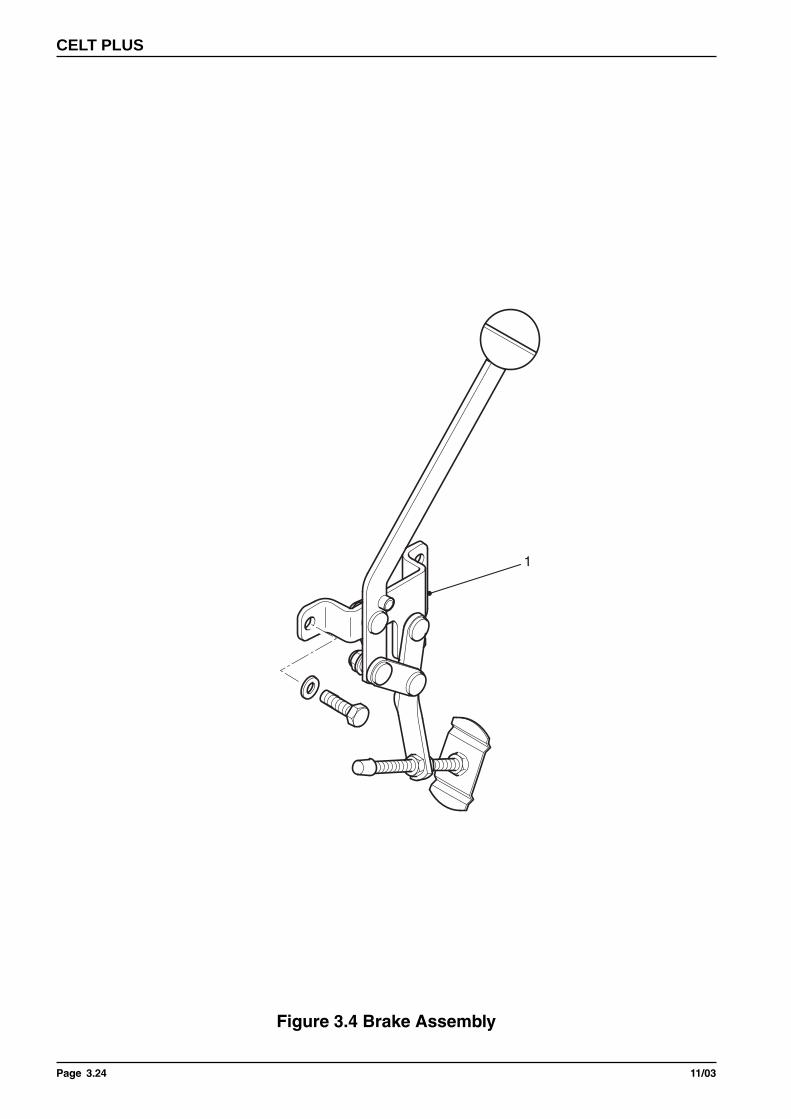
Figure 3.4 Brake Assembly
1
Page 3.2511/03
PARTS LIST
Item Part Number Description
Brake Assembly
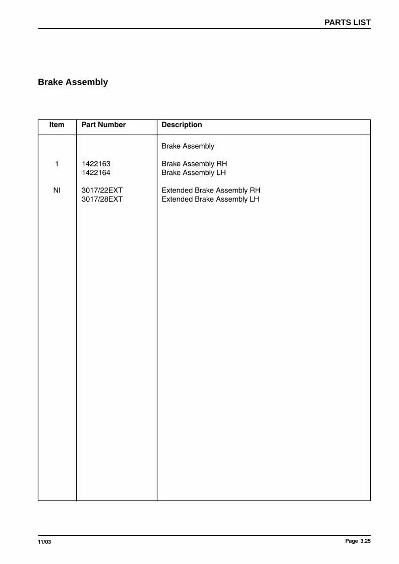
Brake Assembly
1 1422163 Brake Assembly RH1422164 Brake Assembly LH
NI 3017/22EXT Extended Brake Assembly RH3017/28EXT Extended Brake Assembly LH

Page 3.26 11/03
CELT PLUS
Figure 3.5 Castor Wheel Assemblies
(b) Narrow Profile
(a) Wide Profile1
1

Page 3.2711/03
PARTS LIST
Item Part Number Description
Castor Wheel Assembly
Castor Wheel Assembly
1 1190/00WPBLK 190mm Wide Profile Black Castor1 1190/00SLBLK 190mm Narrow Profile Black Castor

Page 3.28 11/03
CELT PLUS
Figure 3.6 (a) Swing/Detachable Footrest Assembly
1 2
3
4
5
6
10
9
7
8
11
Page 3.2911/03
PARTS LIST
Item Part Number Description
Swing/Detachable Footrest Assembly
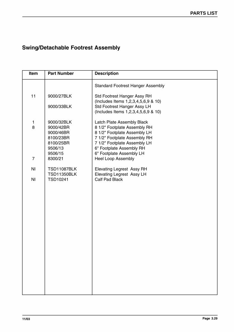
Standard Footrest Hanger Assembly
11 9000/27BLK Std Footrest Hanger Assy RH(Includes Items 1,2,3,4,5,6,9 & 10)
9000/33BLK Std Footrest Hanger Assy LH(Includes Items 1,2,3,4,5,6,9 & 10)
1 9000/32BLK Latch Plate Assembly Black8 9000/42BR 8 1/2" Footplate Assembly RH
9000/46BR 8 1/2" Footplate Assembly LH8100/23BR 7 1/2" Footplate Assembly RH8100/25BR 7 1/2" Footplate Assembly LH9506/13 6" Footplate Assembly RH9506/15 6" Footplate Assembly LH
7 8300/21 Heel Loop Assembly
NI TSD11087BLK Elevating Legrest Assy RHTSD11350BLK Elevating Legrest Assy LH
NI TSD10241 Calf Pad Black

Page 3.30 11/03
CELT PLUS
Figure 3.6 (b) Swing/Detachable Footrest Assembly
14
12 13
910
11
7
8
4
5
6
1 2
315
16
9
10
10
9

Page 3.3111/03
PARTS LIST
Item Part Number Description
Swing/Detachable Footrest Assembly
Rotational Footrest Hanger Assembly
15 3017/AQ Rotational Footrest Hanger Assy RH (Includes Items 1 to 6)3017/AT Rotational Footrest Hanger Assy LH (Includes Items 1 to 6)
1 9000/32BLK Latch Plate Assembly Black8 3013/73 Small Plastic Boot Assembly Includes Items 9 & 10
3015/73 Medium Plastic Boot Assembly Includes Items 9 & 103017/73 Large Plastic Boot Assembly Includes Items 9 & 10
11 3017/78CHR Straight Tube Assembly (Includes Items 9 & 10)16 3017/76CHR Footplate Adj Tube Assy RH (Includes Items 7,9,10,12,13&14)
3017/83CHR Footplate Adj Tube Assy LH (Includes Items 7,9,10,12,13&14)
NI 3017/AQ/EX Ext 4" Rotational Footrest Hanger Assembly RH3017/AT/EX Ext 4" Rotational Footrest Hanger Assembly LH

Page 3.32 11/03
CELT PLUS
Figure 3.8 Seat and Chassis Assembly
4
1
2
3
Page 3.3311/03
PARTS LIST
Item Part Number Description
Seat Assembly
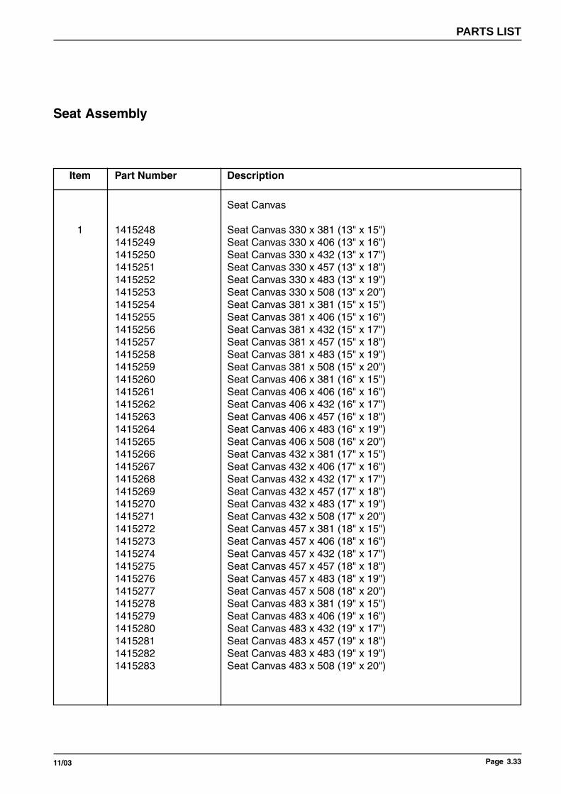
Seat Canvas
1 1415248 Seat Canvas 330 x 381 (13" x 15")1415249 Seat Canvas 330 x 406 (13" x 16")1415250 Seat Canvas 330 x 432 (13" x 17")1415251 Seat Canvas 330 x 457 (13" x 18")1415252 Seat Canvas 330 x 483 (13" x 19")1415253 Seat Canvas 330 x 508 (13" x 20")1415254 Seat Canvas 381 x 381 (15" x 15")1415255 Seat Canvas 381 x 406 (15" x 16")1415256 Seat Canvas 381 x 432 (15" x 17")1415257 Seat Canvas 381 x 457 (15" x 18")1415258 Seat Canvas 381 x 483 (15" x 19")1415259 Seat Canvas 381 x 508 (15" x 20")1415260 Seat Canvas 406 x 381 (16" x 15")1415261 Seat Canvas 406 x 406 (16" x 16")1415262 Seat Canvas 406 x 432 (16" x 17")1415263 Seat Canvas 406 x 457 (16" x 18")1415264 Seat Canvas 406 x 483 (16" x 19")1415265 Seat Canvas 406 x 508 (16" x 20")1415266 Seat Canvas 432 x 381 (17" x 15")1415267 Seat Canvas 432 x 406 (17" x 16")1415268 Seat Canvas 432 x 432 (17" x 17")1415269 Seat Canvas 432 x 457 (17" x 18")1415270 Seat Canvas 432 x 483 (17" x 19")1415271 Seat Canvas 432 x 508 (17" x 20")1415272 Seat Canvas 457 x 381 (18" x 15")1415273 Seat Canvas 457 x 406 (18" x 16")1415274 Seat Canvas 457 x 432 (18" x 17")1415275 Seat Canvas 457 x 457 (18" x 18")1415276 Seat Canvas 457 x 483 (18" x 19")1415277 Seat Canvas 457 x 508 (18" x 20")1415278 Seat Canvas 483 x 381 (19" x 15")1415279 Seat Canvas 483 x 406 (19" x 16")1415280 Seat Canvas 483 x 432 (19" x 17")1415281 Seat Canvas 483 x 457 (19" x 18")1415282 Seat Canvas 483 x 483 (19" x 19")1415283 Seat Canvas 483 x 508 (19" x 20")

Page 3.34 11/03
CELT PLUS
Figure 3.8 Seat and Chassis Assembly
4
1
2
3

Page 3.3511/03
PARTS LIST
Item Part Number Description
4 3015/41/01 381mm (15") Reinforcing Bar3016/41/01 406mm (16") Reinforcing Bar3017/41/01 432mm (17") Reinforcing Bar3018/41/01 457mm (18") Reinforcing Bar3019/41/01 483mm (19") Reinforcing Bar3020/41/01 508mm (20") Reinforcing Bar
2 D20101 M5 x 20 Taptite Screw3 5009551 Upholstery Plastic Washer
Seat Assembly

Page 3.36 11/03
CELT PLUS
Figure 3.10.1 Optional Extras - Set Back Adaptors
2
1
4
3
5

Page 3.3711/03
PARTS LIST
Item Part Number Description
Optional Extras - Set Back Adaptors
Optional Extras
5 3017/BA Backrest Set Back Adaptor RH Includes Items 1,2,3 & 43017/BE Backrest Set Back Adaptor LH Includes Items 1,2,3 & 4
NI 1422212 Arm Set Back Adaptor Assy RH1422213 Arm Set Back Adaptor Assy LH
3 ARMLOCKKIT Armrest Lock Kit AssemblyNI 3017/AD 7 1/2" Stabilser
NI 3917/BA Backrest Set Back Adaptor RH (Used on 21" Seat To Ground)3917/BE Backrest Set Back Adaptor LH (Used on 21" Seat To Ground)
NI 1WLS 1002 Lap BeltNI 6003008 Adjusto Tray CompleteNI 6002949 Tray Support Bracket

Page 3.38 11/03
CELT PLUS

Page 3.3911/03
PARTS LIST
Item Part Number Description
NI 1422214 Seat Canvas 330 x 381 (13" x 15") 17" S.T.G.1422215 Seat Canvas 330 x 406 (13" x 16") 17" S.T.G.1422216 Seat Canvas 330 x 432 (13" x 17") 17" S.T.G.1422217 Seat Canvas 330 x 457 (13" x 18") 17" S.T.G.1422218 Seat Canvas 330 x 483 (13" x 19") 17" S.T.G.1422220 Seat Canvas 330 x 508 (13" x 20") 17" S.T.G.1422221 Seat Canvas 381 x 381 (15" x 15") 17" S.T.G.1422222 Seat Canvas 381 x 406 (15" x 16") 17" S.T.G.1422223 Seat Canvas 381 x 432 (15" x 17") 17" S.T.G.1422224 Seat Canvas 381 x 457 (15" x 18") 17" S.T.G.1422225 Seat Canvas 381 x 483 (15" x 19") 17" S.T.G.1422226 Seat Canvas 381 x 508 (15" x 20") 17" S.T.G.1422227 Seat Canvas 406 x 381 (16" x 15") 17" S.T.G.1422228 Seat Canvas 406 x 406 (16" x 16") 17" S.T.G.1422229 Seat Canvas 406 x 432 (16" x 17") 17" S.T.G.1422230 Seat Canvas 406 x 457 (16" x 18") 17" S.T.G.1422231 Seat Canvas 406 x 483 (16" x 19") 17" S.T.G.1422232 Seat Canvas 406 x 508 (16" x 20") 17" S.T.G.1422233 Seat Canvas 432 x 381 (17" x 15") 17" S.T.G.1422234 Seat Canvas 432 x 406 (17" x 16") 17" S.T.G.1422235 Seat Canvas 432 x 432 (17" x 17") 17" S.T.G.1422236 Seat Canvas 432 x 457 (17" x 18") 17" S.T.G.1422237 Seat Canvas 432 x 483 (17" x 19") 17" S.T.G.1422238 Seat Canvas 432 x 508 (17" x 20") 17" S.T.G.1422239 Seat Canvas 457 x 381 (18" x 15") 17" S.T.G.1422240 Seat Canvas 457 x 406 (18" x 16") 17" S.T.G.1422241 Seat Canvas 457 x 432 (18" x 17") 17" S.T.G.1422242 Seat Canvas 457 x 457 (18" x 18") 17" S.T.G.1422243 Seat Canvas 457 x 483 (18" x 19") 17" S.T.G.1422244 Seat Canvas 457 x 508 (18" x 20") 17" S.T.G.1422245 Seat Canvas 483 x 381 (19" x 15") 17" S.T.G.1422246 Seat Canvas 483 x 406 (19" x 16") 17" S.T.G.1422247 Seat Canvas 483 x 432 (19" x 17") 17" S.T.G.1422248 Seat Canvas 483 x 457 (19" x 18") 17" S.T.G.1422249 Seat Canvas 483 x 483 (19" x 19") 17" S.T.G.1422250 Seat Canvas 483 x 508 (19" x 20") 17" S.T.G.
NI 1422251 17" S.T.G. Swinging Brkt Assy RH1422252 17" S.T.G. Swinging Brkt Assy LH
Optional Extras - 17" Seat To Ground Seat Canvas

Page 3.40 11/03
CELT PLUS
Figure 3.10.2 Optional Extras - Headrest
12
3
4
5
6

Page 3.4111/03
PARTS LIST
Item Part Number Description
Optional Extras - Headrest
Headrest
6 3013/91 Headrest Kit 13" Wide (15" High)3015/91 Headrest Kit 15" Wide (15" High)3016/91 Headrest Kit 16" Wide (15" High)3017/91 Headrest Kit 17" Wide (15" High)3018/91 Headrest Kit 18" Wide (15" High)3019/91 Headrest Kit 19" Wide (15" High)
1 5050/26 Headrest Pad Assy
2 5050/39 Adjustment Clamp Assy
3 5050/31/01-12 CHR Headrest Vertical Adj Tube Assy 12" Long5050/31/01-15 CHR Headrest Vertical Adj Tube Assy 15" Long
4 3017/92 Headrest Brace Brkt Assy
5 3013/95 Headrest Lateral Adj Tube Assy 13" Wide3015/95 Headrest Lateral Adj Tube Assy 15" Wide3016/95 Headrest Lateral Adj Tube Assy 16" Wide3017/95 Headrest Lateral Adj Tube Assy 17" Wide3018/95 Headrest Lateral Adj Tube Assy 18" Wide3019/95 Headrest Lateral Adj Tube Assy 19" Wide

INVACARE INTERNATIONAL
Belgium & Luxemburg: Autobaan 14 · B-8210 Loppem
Danmark: Sdr. Ringvej 39 · DK-2605 Brøndby
Deutschland, Österreich, Switzerland & East Europe: Dehmer Straße 66 · D-32549 Bad Oeynhausen
España: c/ Areny · s/n Polígon Industrial de Celrà · E-17460 Celrà (Girona)
France: Les Roches · F-37230 Fondettes
Italia: Via dei Pini 62 · I-36016 Thiene (VI)
Nederland: Celsiusstraat 46 · NL-6716 BZ Ede
Norge: Grensesvingen 9 · N-0603 Oslo
Portugal: Rua Senhora de Campanhã 105 · P-4369-001 Porto
Sverige & Suomi: Fagerstagatan 9 · P.O. Box 66 · S-163 91 Spånga
United Kingdom & Eire: South Road · Bridgend Industrial Estate · Bridgend CF31 3PY · UK
Part
No:
14
2021
9 -
030
4 (G
B)