Embed Size (px)
Citation preview

International Flame Research Foundation
The Finnish and Swedish National Committees Finnish – Swedish Flame Days 2013
- 1 -
Investigating Potential Problems and Solutions of Renewable Fuel Use in Steel Reheating Furnaces
John NISKA*A, Carl-Erik GRIP B, Pelle MELLIN C
A) Swerea MEFOS, Heating and Metalworking Department, Luleå
B) Luleå University of Technology, Division of Energy Science, Luleå
C) KTH Royal Institute of Technology, Division of Energy and Furnace Technology, Stockholm
* Corresponding author, [email protected]
ABSTRACT Implementing renewable fuels in steel reheating furnaces can reduce carbon dioxide emissions from fossil fuels, so the steel industry is interested in finding the optimal method of implementation. The relatively low cost of solid biofuels from forest products make them an attractive candidate, but there is a risk of reaction between pellets ash and furnace brick. Therefore a test was conducted with wood pellets ash on a furnace brick to test the sensitivity to pellets ash. One problem is the formation of a glassy phase due to the interaction of furnace refractories with pellets ash. The risk for the formation of a glassy phase depends on the composition of the refractory, composition of the ash and the furnace conditions, for example, a glassy phase was found to form on a chamotte refractory furnace brick when a pellets ash and the brick were heated to 1200°C.
One method to analyze the risk for volatile and low melting point compounds from solid biofuels is to use a tertiary phase diagram to divide various components in the ash. Oxides and compounds rich in the alkali metals (Na and K) tend to form volatile compounds. These alkali metal oxides together with silica can give low melting point phases for compositions near the bottom of this diagram. Ash compositions near the top of the diagram which are rich in CaO and MgO tend to have higher melting points. The wood pellets ash investigated was analysed and found to contain a large percentage of Ca, Si and Mg, expressed as CaO (44.4%), SiO2 (14.6%) and MgO (10.1%) and relatively modest amounts of the alkali metals Na and K expressed as Na2O (3.5%) and K2O (6.2%). This mostly stem wood pellets ash could give concern with the formation of a glassy phase, so biofuels with more twigs, leaves and bark with a higher concentration of alkali metals could give even greater concerns. Therefore alternatives like gasification should be considered.
Gasification of solid biofuels is one way to avoid ash-forming compounds in reheating furnaces. A survey was performed to evaluate different gasification technologies, as well as existing applications of syngas in other high-temperature industries.
Keywords: biofuels; ash; furnace;steel;refractories

International Flame Research Foundation
The Finnish and Swedish National Committees Finnish – Swedish Flame Days 2013
- 2 -
1 Introduction The steel industry is a large consumer of fossil fuels both for steelmaking and hot working which leads to large amounts of carbon dioxide (CO2) emissions. The European Union has the goal of reducing CO2 emissions 80% by the year 2050, which together with taxes and the use of CO2 emission rights have stimulated research into new methods and techniques for implementing renewable fuels. Decreasing the use of fossil fuels with the implementation of biofuels in steel reheating furnaces is the goal of this project sponsored by the Swedish Steel Producers Association (Jernkontoret). This paper will primarily focus on the use of renewable fuels based on forest products, which are relatively readily available in N. Europe.
2 Background 2.1 Reheating furnace A reheating furnace is used to heat the steel before being hot rolled into various products as plates, thin strips, bars and profiles. The steel comes in various forms and are typically heated to a temperature, usually around 1100-1300°C, suitable for plastic deformation in the hot rolling process. Figure 1 shows a schematic overview of a reheating furnace.
Fuel supply
Figure 1. Example of a reheating furnace. During the reheating process, the stock is charged into the furnace, and passes through three furnace zones (preheating, heating and soaking) in a continuous reheating furnace There are also batch reheating furnaces (for example, pit furnaces) in which the steel stock is heated in one position. Heat is transferred to the steel by means of convection and radiation from the burners and furnace walls. The temperature of the incoming steel may range from ambient temperatures up to 800°C, depending on whether or not hot charging is used. The final temperature required in the stock leaving the furnace depends on various factors including the rolling process and steel grade. The objective of the reheating furnace is to heat up the steel, as homogeneously as possible, to the target temperature.

International Flame Research Foundation
The Finnish and Swedish National Committees Finnish – Swedish Flame Days 2013
- 3 -
2.2 Potential CO2 reductions The goal of this project is to reduce the carbon dioxide emissions due to fossil fuels in steel reheating furnaces by 60 000 tons by the year 2020 and 124 000 tons by the year 2025 with the implementation of renewable fuels.
2.3 Challenges when switching fuels It is possible to directly fire a steel reheating furnace with wood powder produced from wood pellets. This technology is commercially available, for example, in power plants built for district heating. Firing a wood powder is much different than the fossil fuels currently in use, for example, fuel oil, propane and natural gas. A major difference is the presence of large amounts of wood ash which would contaminate the furnace refractories, air preheating system, steel stock, etc. There is a risk that ash can combine with iron oxide scale in the furnace, evaporate and form deposits in the recuperator or other cooler metal surfaces, etc. Therefore this investigation into the effects of wood pellet ash on the steel reheating process is critical before attempting large industrial trials.
3 Experimental Wood pellets are available commercially from various manufacturers. Pellets from a local supplier, BioEnergi i Luleå AB, were chosen for this investigation. Their pellets are manufactured from local forest products, and the forests in N. Europe are primarily composed of soft woods or coniferous trees. The pellets have an effective calorific energy of at least 17.6 MJ/kg (4.9 kW-h/kg) with an ash content of max. 0.4% (dry weight) with max. 8 % moisture and no binder compounds (http://www.bioenergilulea.se). Ash from these pellets was obtained from a local district heating plant. The ash was analysed at Calderys Nordic AB with the results given in Table 1.
Table 1. Major components in the wood ash expressed as oxides
Component CaO SiO2 MgO K2O Al2O3 SO3 Na2O Fe2O3 Mass % 44.44 14.6 10.1 6.2 3.77 3.77 3.47 3.15
This ash was mixed with powdered iron oxide scale made by grinding a 2 cm thick scale formed on a low Si carbon steel alloy (0.13% C, 0.2% Si, 0.7% Mn) after a long heating cycle at 1250°C. The ash and scale were mixed to give from 0% to 50 wt% ash and placed on alumina holders made from an alumina pipe. Ash was also place on small specimens of various steel alloys to investigate if there would be a reaction between the ash and steel. These two tests were made using a chamber furnace at Swerea MEFOS at 1150°C and 1250°C with 2% excess oxygen for 1 hr. These tests are shown in Figures 2 and 3, with results summarized in Table 2.

International Flame Research Foundation
The Finnish and Swedish National Committees Finnish – Swedish Flame Days 2013
- 4 -
Figure 2. Ash on steel specimens and as an ash plus steel scale powder on alumina holders before entering the furnace
1150°C 1250°C
Figure 3. Results for the ash plus steel scale powder on alumina holders after the furnace cycle
Table 2. Description of the solids formed in the ash plus scale tests
Mass % ash1 1150°C 1250°C 0 Hard Hard 5 Hard Hard 10 Hard Hard 25 Soft Molten phase 50 Soft Molten phase 1The balance is a steel scale powder (Fe2O3, Fe3O4 and FeO) formed at 1250°C
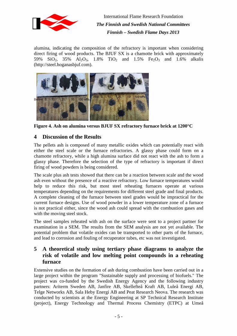
Another test was made by placing pellets ash mixed with another type of steel scale on both alumina holders and a BJUF SX refractory furnace brick from Höganäs Bjuf. The specimens were heated for 4 hrs at 1200°C in air in a laboratory furnace, with the results given in Figure 4. The pellets ash gave a glassy phase on the surface of the furnace brick, but the pure scale did not melt. The ash did not form a glassy phase on the
International Flame Research Foundation
The Finnish and Swedish National Committees Finnish – Swedish Flame Days 2013
- 5 -
alumina, indicating the composition of the refractory is important when considering direct firing of wood products. The BJUF SX is a chamotte brick with approximately 59% SiO2, 35% Al2O3, 1.8% TiO2 and 1.5% Fe2O3 and 1.6% alkalis (http://steel.hoganasbjuf.com).
Figure 4. Ash on alumina versus BJUF SX refractory furnace brick at 1200°C
4 Discussion of the Results The pellets ash is composed of many metallic oxides which can potentially react with either the steel scale or the furnace refractories. A glassy phase could form on a chamotte refractory, while a high alumina surface did not react with the ash to form a glassy phase. Therefore the selection of the type of refractory is important if direct firing of wood powders is being considered.
The scale plus ash tests showed that there can be a reaction between scale and the wood ash even without the presence of a reactive refractory. Low furnace temperatures would help to reduce this risk, but most steel reheating furnaces operate at various temperatures depending on the requirements for different steel grade and final products. A complete cleaning of the furnace between steel grades would be impractical for the current furnace designs. Use of wood powder in a lower temperature zone of a furnace is not practical either, since the wood ash could spread with the combustion gases and with the moving steel stock.
The steel samples reheated with ash on the surface were sent to a project partner for examination in a SEM. The results from the SEM analysis are not yet available. The potential problem that volatile oxides can be transported to other parts of the furnace, and lead to corrosion and fouling of recuperator tubes, etc was not investigated.
5 A theoretical study using tertiary phase diagrams to analyze the risk of volatile and low melting point compounds in a reheating furnace
Extensive studies on the formation of ash during combustion have been carried out in a large project within the program "Sustainable supply and processing of biofuels." The project was co-funded by the Swedish Energy Agency and the following industry partners: Ariterm Sweden AB, Janfire AB, Skellefteå Kraft AB, Luleå Energi AB, Telge Networks AB, Sala Heby Energi AB and Peat Research Neova. The research was conducted by scientists at the Energy Engineering at SP Technical Research Institute (project), Energy Technology and Thermal Process Chemistry (ETPC) at Umeå
International Flame Research Foundation
The Finnish and Swedish National Committees Finnish – Swedish Flame Days 2013
- 6 -
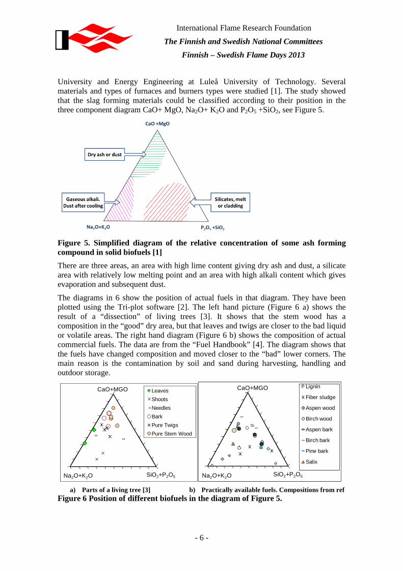
University and Energy Engineering at Luleå University of Technology. Several materials and types of furnaces and burners types were studied [1]. The study showed that the slag forming materials could be classified according to their position in the three component diagram CaO+ MgO, Na2O+ K2O and P2O5 +SiO2, see Figure 5.
Figure 5. Simplified diagram of the relative concentration of some ash forming compound in solid biofuels [1] There are three areas, an area with high lime content giving dry ash and dust, a silicate area with relatively low melting point and an area with high alkali content which gives evaporation and subsequent dust.
The diagrams in 6 show the position of actual fuels in that diagram. They have been plotted using the Tri-plot software [2]. The left hand picture (Figure 6 a) shows the result of a “dissection” of living trees [3]. It shows that the stem wood has a composition in the “good” dry area, but that leaves and twigs are closer to the bad liquid or volatile areas. The right hand diagram (Figure 6 b) shows the composition of actual commercial fuels. The data are from the “Fuel Handbook” [4]. The diagram shows that the fuels have changed composition and moved closer to the “bad” lower corners. The main reason is the contamination by soil and sand during harvesting, handling and outdoor storage.
LeavesShootsNeedlesBarkPure TwigsPure Stem Wood
CaO+MGO
SiO2+P2O5Na2O+K2O
Lignin
Fiber sludge
Aspen wood
Birch wood
Aspen bark
Birch bark
Pine bark
Salix
CaO+MGO
SiO2+P2O5Na2O+K2O a) Parts of a living tree [3]
b) Practically available fuels. Compositions from ref Figure 6 Position of different biofuels in the diagram of Figure 5.

International Flame Research Foundation
The Finnish and Swedish National Committees Finnish – Swedish Flame Days 2013
- 7 -
These ashes will be injected directly into the furnace if those fuels are used in a powder burner to heat the furnace. The diagram in Figure 7 shows the amount of important ash forming substances from some different types of fuels. The amounts are calculated using a spread sheet system model. A logarithmic scale is used because of the large difference between the fuel types.
0,01
0,1
1
10
100
1000
kg/k
ton
slab
s
CaO
SiO2
Al2O3
K2O
Na2O
Figure 7. The amount of important ash forming substances from some different types of fuels Wood powder is a relatively clean powder made from stem wood. The process economics could be improved by using cheaper by-product biomass like branch and crown, stumps or bark. However these fuels also create a high amount of ash. The last point describes the ash from a residue created as by-product from a new hydrolysis process, where hemicelluloses are extracted from wood by high temperature high pressure liquid [5] . Use of such types of by-product fuels could be one possibility to create a fuel with an acceptable ash concentration.
Figure 7 shows the total amount of ash, while the important questions include, what are the amounts that pass through the furnace and how much will stick to the walls or to the slabs? Our knowledge is presently insufficient to answer these questions. The alkali metals are in a gaseous phase for high furnace temperatures, so the main part will probably pass through. Maybe part of them will condense on the cold slabs entering the furnace.
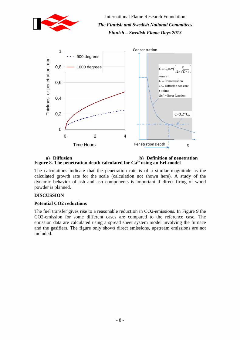
If ash sticks onto the slabs, then it can react with the iron oxide scale present. Here the kinetics is important. Does it penetrate or stay on the surface? This was investigated using a simple diffusional calculation of the penetration depth for Ca2+ (see Figure 8). Figure 8 shows the penetration of CaO in a shell of FeO. Figure 8b shows the calculation principle. The calculation was made with using an Erf model and the penetration depth was defined as the point where the concentration reached 20% of the surface concentration. Diffusion constants for Ca2+ were taken from ref. [6]
International Flame Research Foundation
The Finnish and Swedish National Committees Finnish – Swedish Flame Days 2013
- 8 -
X
Concentration
Penetration Depth
functionError time
constantDiffusion ionConcentrat
:20
====
××
×=
ErftDGwhere
tDxerfCC
C=0,2*C0
0
0,2
0,4
0,6
0,8
1
0 2 4
Time Hours
Thic
knes
or p
enet
ratio
n, m
m
900 degrees
1000 degrees
a) Diffusion b) Definition of penetration
Figure 8. The penetration depth calculated for Ca2+ using an Erf-model The calculations indicate that the penetration rate is of a similar magnitude as the calculated growth rate for the scale (calculation not shown here). A study of the dynamic behavior of ash and ash components is important if direct firing of wood powder is planned.
DISCUSSION Potential CO2 reductions The fuel transfer gives rise to a reasonable reduction in CO2-emissions. In Figure 9 the CO2-emission for some different cases are compared to the reference case. The emission data are calculated using a spread sheet system model involving the furnace and the gasifiers. The figure only shows direct emissions, upstream emissions are not included.

International Flame Research Foundation
The Finnish and Swedish National Committees Finnish – Swedish Flame Days 2013
- 9 -
0
25
50
75
Ref (LPG) LNG powder 25%
LNG 25% powder
Powder 100%
Entr. Flow gasifier
kg C
O2/
t Sl
abs
Figure 9. CO2 emissions with different process combinations. Only direct emissions are included The reference case is the present situation with LPG (or propane) steel reheating. The next case shows the effect of changing the fuel to natural gas. This gives a CO2 reduction which however is relative limited. After that the introduction of wood fuel through powder burners is shown. In the first stage only part of the fuel is changed. This can be preferable, firstly because of investment cost, but also because of the probable effect on flame structure is of less importance at the colder inlet end of the furnace. Finally, a transfer to 100 % renewable fuel through the use of a gasifier or wood powder decreases CO2 to zero. It should be noted that this is true only if we look at direct emissions, if upstream data were included there would be a small emission also for the production of the biofuel. There is a total potential savings of around 70 kgCO2/t.
CONCLUSIONS Wood products contain ash which can pose problems for both the furnace refractories and other furnace parts. One solution is to only use wood fuels at low enough temperatures that molten and volatile phase are not a problem. This would severely limit the application of these solid fuels. Another solution is to first gasify the solid fuels to form a relatively clean syngas. There are many possible methods for generating a syngas, which could be examined in future research.
6 Gasification as a method to use renewable fuels and overcome ash-related problems in steel reheating furnaces
In this part we have looked at gasification as a commercially available way for using wood-based renewable fuels in high-temperature combustion processes.
There are two types of fuel gas that are derived from biomass; biogas and synthesis gas. Syngas is produced through a gasification process, while biogas is obtained through fermentation
Syngas is a mixture of hydrogen and carbon monoxide in varying amount, it also contains small amount of methane, and inert gases such as carbon dioxide and nitrogen.

International Flame Research Foundation
The Finnish and Swedish National Committees Finnish – Swedish Flame Days 2013
- 10 -
The composition of the syngas depends on feedstock material, gasification process and technology.
The integration of a gasifier to a reheating furnace has been done in other parts of the world, however mostly with coal as feedstock. The coal gas is often blended with blast furnace gas (BFG) and coke oven gas, especially in large steel plants in China.
Large scale integration to reheating furnaces with biobased syngas have yet to become reality. Small scale integration is done in India but according to the literature survey, no large scale gasification has been carried out since steel producers are mostly small to medium scale enterprises.
In comparison with solid fuels combustion, a lower amount of contaminants are achieved if the fuel is first gasified and then combusted. Still a number of contaminants may be found in the gas. They may be categorized as:
1. Tar 2. Sulphur compounds 3. Nitrogen containing compounds 4. Particulate matter 5. Halogen species (mainly HCl) 6. Alkali metal species 7. Other contaminants (trace metals, Phosphorus species etc.)
(1) Tars are a problem related to some gasification setups that must be considered. However since the Tar will be combusted at high temperatures they will mostly cause problems in earlier stages, such as in the supply line to the reheating furnace. (2) Sulfur compounds, mostly relevant where coal is used, are reduced in the fuel supply by gasification. (3) Nitrogen containing compounds are decreased, however in combustion these compounds will react to form NOx which can be dealt with conventional NOx-reduction techniques. (4) Particulate matter could be a problem with certain gasifier types, but are usually remedied by using cyclones and textile particle filters. (5) Halogen species, such as Cl and Br, will cause formation of HCl and HBr respectively. These are a corrosive components and HCl specifically is known to take part in corrosion cycles that cause problems in boilers [7]. In gasification of biomass, the HCl content in the syngas has been found significant, for example Simell et al. recorded peaks up to 90 ppm in syngas [8]. (6) Gasification can especially reduce the ash and alkali metals content. Alkali metals content in the gas phase can be measured with new technologies. For example [9], showed that a mix of pine and spruce give a very low alkali metals content: for K and Na, from 140 to 350 ppbK and from 1.7 to 60 ppbNa respectively. (7) Other contaminants include phosphorus species and other metallic elements. A few studies on phosphorous species in syngas have been made; Porbatzki et al [10] measured the concentration of gaseous phosphorous species and found that very low amounts are carried with the syngas. Primarily, this is due to the formation of phosphates, which remains in the solid residue after gasification. As a little work has been done in this area, any conclusion should be made with reservation; though it seems

International Flame Research Foundation
The Finnish and Swedish National Committees Finnish – Swedish Flame Days 2013
- 11 -
most of the problems in combustion related to phosphor in biomass is avoided by gasifying the solid fuel.
In conclusion, the contaminants that eventually could cause problems are likely Cl and where temperature decreases, such as in the chimney of the reheating furnace, the alkali metals Na and K.
Gasification technologies may be categorized according the configurations and have different properties as shown in Table 3. Generally the amount of contaminants is low for downdraft and entrained flow. Due to simplicity fixed bed gasification is quite widespread in India and China; updraft is used where fuel flexibility is needed and downdraft where a clean syngas is required.
Table 3. Gasification setups
Gasification technology
Fixed bed Fluidized bed Entrained flow Updraft Downdraft Bubbling Circulating
Scale up limit <10 t/h <15 t/h No scale limit
No scale limit
Up to 700 MWth
Operating pressure (bar)
Atmospheric Atmospheric 1-35 1-19 20-50
Operating temp. (°C)
300-1000 300-1000 650-950 800-1000 >1200
Tar content in syngas (mg/Nm3)
35000 500-1000 13500 Low Almost tar free
Syngas quality
Low (Syngas contains high tars)
Low ( syngas contains high CO2)
Medium (syngas is rich in particulates)
Medium (syngas is rich in particulates)
High quality (syngas with tar free)
Complexity Simple Simple Advanced Advanced Advanced
Integration of gasification to a reheating furnace could either be directly with hot syngas entering the furnace or indirectly when cold syngas is used. The extent of required gas cleaning is in the case of hot gas determined by the application and in the case of cold gas determined by the supply system. When using cold gas, for example, the Tar compounds in the gas might condense in the pipes and thus have to be removed before entering the fuel feeding system. When using hot gas to fuel lime kilns, the gas cleaning are sometime non-existing (except for cyclones) since the lime production do not suffer from small amounts of contaminants.
For a reheating furnace, the gas cleaning required for pressurizing cold gas will for sure be sufficient to use the gas in a reheating furnace. When using hot gas problems may be experienced when using a fluidized bed gasifier without gas cleaning. However in this
International Flame Research Foundation
The Finnish and Swedish National Committees Finnish – Swedish Flame Days 2013
- 12 -
literature review, no gasification equipment has been found directly unsuitable. The facilities’ scale of production and investment costs should primarily be considered when selecting gasification equipment.
7 Acknowledgements The authors would like to thank the Swedish Energy Agency for their financial support through the Swedish Steel Producers Association (Jernkontoret) and our project partners.
REFERENCES [1] M Rönnbäck et al, “Combustion characterization and combustion technique
evaluation of different pellet fuels - project synthesis”, Final report on the project "Sustainable supply and refining of biofuels" to Swedish Energy agency, Borås, Sweden 2011 (in Swedish)
[2] Graham & Midgley, 2000, http://www3.interscience.wiley.com/cgibin/jabout/2388/OtherResources.html.
[3] J. Werkelin Report 08-06. “Ash-forming elements and their chemical forms in woody biomass fuels”, PhD Thesis Åbo Akademi 2008
[4] B. Strömberg, S H Svärd, ”Bränslehandboken 2012”, VÄRMEFORSK Serviceaktiebolag, Stockholm, April 2012
[5] J. Lundgren & J. Helmerius (2009). “Integration of a hemicellulose extraction process into a biomass based heat and power plant”, Proceedings of ECOS 2009. Foz do Iguaçú : ABCM, Brazilian Society of Mechanical Sciences and Engineering
[6] Fukuyama H, Hossain M K, and Nagata K, Solid-State Reaction Kinetics of the System CaO-FeO, Metallurgical and Materials Transactions B Volume 33b, April 2002.
[7] H.P. Nielsen, F.J. Frandsen, K. Dam-Johansen, L.L. Baxter (2000). ”The implications of chlorine-associated corrosion on the operation of biomass-fired boilers”. Progress in Energy and Combustion Science 26 283–298
[8] P. Simell, P. Stahlberg, Y. Solantausta, J. Hepola, E. Kurkela (1997). ”Gasification gas cleaning with nickel monolith catalyst”. In: Bridgwater AV, Boocock DGB, editors. Developments in thermochemical biomass conversion; 1997. Banff: Blackie Academic and Professional; 1997. p. 1103-1116.
[9] C. Erbel, M. Mayerhofer, P. Monkhouse, M. Gaderer, H. Spliethoff (2012). “Continuous in situ measurements of alkali species in the gasification of biomass”. Proc. Combust. Inst. 34 (2) 2331-2338.
[10] D. Porbatzki, M. Stemmler, M. Muller (2011). “Release of inorganic trace elements during gasification of wood, straw, and miscanthus”. Biomass and bioenergy 35, p 79-86.