Embed Size (px)
Citation preview

Scientia Iranica B (2016) 23(2), 575{587
Sharif University of TechnologyScientia Iranica
Transactions B: Mechanical Engineeringwww.scientiairanica.com
Investigating the e�ects of ionic polymer metalcomposite patches on aeroelastic characteristics of acantilever wing in supersonic ow
S. Jamshidi, M. Dardel� and M.H. Pashaei
Department of Mechanical Engineering, Babol Noshirvani University of Technology, Babol, P.O. Box 484, Iran.
Received 4 February 2014; received in revised form 13 November 2014; accepted 23 May 2015
KEYWORDSEnergy harvesting;IPMC;Flutter;Limit cycle;Supersonic ow.
Abstract. This work presents energy harvesting from the limit cycle oscillation oflow aspect ratio rectangular cantilever wings in supersonic ow. The wing is modeledaccording to the classical plate theory with von-Karman strain-displacement relationsfor modeling large de ections due to mid-plane stretching. The aerodynamic pressureis evaluated based on the quasi-steady �rst-order piston theory. Linear and nonlinearaeroelastic characteristics of the considered model are accurately examined and the e�ectsof Ionic Polymer Metal Composite (IPMC) energy harvesting on utter margin and limitcycle oscillation amplitudes are investigated. It is shown that the position of IPMC onthe wing has a great e�ect on the amount of harvested power. Since IPMC induces ahigh level of strain, it produces the static de ection of the wing. This static de ectionproduces sti�ness hardening of the entire system, and, accordingly, can greatly reduce theamplitude of limit cycle oscillation. Obtained results show that the IPMC actuator hasmore in uence on the limit cycle oscillation of the wing, while its e�ect on utter instabilityis negligible.© 2016 Sharif University of Technology. All rights reserved.
1. Introduction
Research interest in converting ambient vibration en-ergy to usable electrical energy has increased in thelast few years. The concept of energy harvestingis particularly useful for wireless sensors powered bybatteries, and remotely operated systems with a limitedenergy source. The goal of the research into vibration-based energy harvesting is to provide electrical energyfor such systems by utilizing the vibrations available intheir environment. Already, active materials have beenexplored as mechanical to electrical energy transducers.Ionic polymers o�er several advantages as the choice ofactive material for the speci�c application. They havethe potential for further development as electromechan-
*. Corresponding author.E-mail address: [email protected] (M. Dardel)
ical transducers. When these polymers are bent, apotential di�erence between the electrodes is produced.This process is the conversion of mechanical energyto electrical energy. Electrical energy is stored in anelectric circuit or consumed.
Electro Active Polymers (EAP) are divided intotwo categories; electronic, driven by an electric �eld,and ionic, driven by the di�usion of ions. As stated,the di�usion of ions is the electromechanical couplingin ionic polymers, speci�cally, the motion of mobilecations. Ionic polymer material has both �xed anionsand mobile cations. When the material is hydrated,the cations will di�use towards an electrode on thematerial surface under an applied electric �eld. Insidethe polymer structure, anions in the interconnectedclusters provide channels for the cations to ow towardsthe electrode. This motion of ions causes the structureto bend toward the anode [1]. Conversely, bending

576 Sh. Jamshidi et al./Scientia Iranica, Transactions B: Mechanical Engineering 23 (2016) 575{587
the ionic polymers will force ion di�usion and producevoltage. IPMC consists of a base polymer coated witha metal to act as electrodes.
The electromechanical coupling of EAPs is char-acterized by high strain, low stress, fast reaction speed,and low drive voltage. Because base material is apolymer, ionic polymer actuation can range to strainsof > 10%. EAPs only require a few volts for actuation,usually less than 10 V [1]. While ionic polymersbelong to a larger class of material EAPs, piezoelectricmaterials are a type of ferroelectric material. Piezo-electric materials have the opposite characteristics ofionic polymers. Piezoelectric materials produce lowstrain, but large stress. Typical strains for piezoelectricmaterials are between 0.1% and 0.3%, while generatedstress varies between 30 and 40 MPa. Another dif-ference is the drive voltage. Ionic polymers can beactivated with low voltages, but piezoelectric materialshave actuation values of 50 to 800 V. Therefore, thevoltage produced during energy harvesting for ionicpolymers is less than piezoelectric materials. Most ofthe piezoelectric materials used for engineering pur-poses are ceramic. Because piezoelectric materials area more rigid structure, they can produce larger forces.Typically, they have an elastic modulus of 50 GPa inthe poling direction and 62 GPa in a perpendiculardirection, but ionic polymers have an elastic modulusfrom 150 MPa to 400 MPa [2].
Energy harvesting from base vibration is studiedin [3]. Energy harvesting from ambient environments,which is an important source of energy harvesting, isconsidered in [4]. Fluid-structure interaction is oneof these environmental sources. Small diaphragms inpressurized ow channels [5] and large-scale vortexinduced vibration based harvesters are other examplesof this type [6]. In [7], oscillations induced in a exibleduct wall are considered an energy source. Energyharvesting from low speed ow using small cantileverpiezoelectric elements due to external excitation of agust generator has been studied by [8]. De Marquiet al. investigated harvesting electrical energy fromaeroelastic vibrations of the lifting surfaces of UAVsand MAVs, due to their relatively exible wings [9].Recently, marine environments have been introducedas a new energy source. These environments, such asbeaches and rivers, also show good potential for energyharvesting, so designing an energy harvester for theseenvironments is necessary. Taylor et al. designed anenergy harvester that produces power at relatively low ow speeds [10]. In work done by Dunnmon et al., a exible beam with piezoelectric laminates excited by auniform axial ow is used as an energy source, whosepower is delivered to an electrical impedance load [11].
Aeroelastic systems have di�erent sources of non-linearity due to their multidisciplinary nature. Thesenonlinearities may be in the form of structural or
aerodynamics types, which result in chaos, limit cycles,and other types of nonlinear behavior. A review of thenonlinear aeroelasticity �eld and related topics is givenin [12]. The main focus of available work on the energyharvesting of aeroelastic systems is on piezoelectricmaterials. These materials are known to have verygood properties and are extensively studied in relatedliterature. In this work, the in uence of energyharvesting on the nonlinear aeroelastic response of acantilevered plate with IPMC laminates is addressed.The nonlinear structural model considered in this workis a nonlinear plate model, based on the classicalplate model, with large de ection strains, accordingto von-Karman theory [13]. These strains are due toin-plane stretching. For aerodynamic modeling, thequasi-steady �rst-order piston theory is used [14]. At�rst, modeling of structural, aerodynamics, and ionicpolymer metal composites is illustrated. Then, thevalidity of these equations is shown and their obtainedresults are presented. Finally, the conclusion to theproblem is given.
2. Theoretical analysis
The aeroelastic model with attached harvester is shownin Figure 1. The model consists of a cantileveredwing with IPMC laminates attached in a bimorphcon�guration. The rectangular wing has span, L,chord, c, and thickness, hp. The equations of motionof the wing with embedded IPMC can be derived asfollows.
2.1. Modeling wing in according to classicalplate theory
In classical plate theory, displacement components ata point of height z from the mid-plane of the plate canbe expressed as:
up(x; y; z; t) = �z @w0(x; y; t)@x
;
vp(x; y; z; t) = �z @w0(x; y; t)@y
;
wp(x; y; z; t) = w0(x; y; t); (1)
Figure 1. Thin cantilevered wing with embedded IPMCpatches and its cross-sectional view.

Sh. Jamshidi et al./Scientia Iranica, Transactions B: Mechanical Engineering 23 (2016) 575{587 577
where up and vp denote in-plane, and wp denotes trans-verse displacements of any point of a cross section ofthe plate. The subscript `0' refers to the displacementof a point in a mid-plane. Using von-Karman strain-displacement relations, the nonlinear strain �eld can beexpressed as [15]:8<:�xx�yy xy
9=; =
8>><>>:�(0)xx
�(0)yy
(0)xy
9>>=>>;+ z
8>><>>:�(1)xx
�(1)yy
(1)xy
9>>=>>;=
8>>>><>>>>:12
�@w0@x
�212
�@w0@y
�2
@w0@x
@w0@y
9>>>>=>>>>;+ z
8>>><>>>:�@2w0
@x2
�@2w0@y2
�2@2w0@x@y
9>>>=>>>; ;
�zz = �xz = �yz = 0: (2)
According to the classical plate theory, the strainenergy of the plate is given by:
Pp =12
ZZZVp
[�xx"xx + �yy"yy + �xy xy]dxdydz; (3)
where:
�xx =Ep
1� �2p
["xx + �p"yy];
�yy =Ep
1� �2p
["yy + �p"xx];
�xz =Ep
2(1 + �p) xz: (4)
Ep and �p are Young's module of elasticity and Pois-son's ratio of the plate, respectively. By substitutingEq. (4) into Eq. (3), strain energy can be expressed as:
Pp =Ep
2(1� �2p)
ZZZVp
["2xx + 2�p"xx"yy + "2
yy
+1� �p
2 2xy]dxdydz: (5)
Finally, the strain energy is given by:
Pp =Ep
2(1� �2p)
ZZ (h
"14
�@w0
@x
�4
+14
�@w0
@y
�4
+�p2
�@w0
@x
�2�@w0
@y
�2
+1��p
2
�@w0
@x@w0
@y
�2#
+h3
12
" @2w0
@x2
!2
+2�p@2w0
@x2@2w0
@y2 +�@2w0
@y2
�2
+2(1� �p)�@2w0
@x@y
�2#)
dxdy: (6)
The kinetic energy of the plate with mass density of �pcan be expressed as:
Tp=12
ZZZVp
�p
"��z @ _w0
@x
�2
+��z @ _w0
@y
�2
+ _w20
#dxdydz:
(7)
2.2. Modeling the IPMC patchesBuechler [16] represented the relation between stressand electric displacement of IPMC materials as follows:�
TD
�=�cD �cDdcDd �T
� �SEv
�; (8)
where T and S represent mechanical stress and strain,E and D denote the electric �eld and displacement,d is the strain coe�cient, cD denotes the sti�ness,and superscript D indicates that it is measured underconstant electric displacement. �T is the dielectricpermittivity and its superscript, T , indicates that itis determined under constant stress. Also, compressedtensor notation, known as Voigt notation, is useddue to the symmetry of the strain and stress tensors.These constitutive laws can describe the piezoelectrice�ect, the driving phenomenon sensors, actuators,and, most recently, energy harvesters. They may bederived directly through a linear electrical enthalpyexpression [17]:
Hi =12TS � 1
2EvD; (9)
which, considering Eq. (8), can be expanded into thefollowing form:
Hi =12ScDS � ScDdEv � 1
2�TE2
v : (10)
The electromechanical energy within the IPMC lami-nates is written as de�ned by the enthalpy function inEq. (10), and is also integrated over the total volume(Vi) of the laminates as:
Hi =ZZZ �
12ScDS � ScDdEv � 1
2�TE2
v
�dVi:
(11)
The sti�ness and strain of IPMC laminates are asfollows (with IPMC nonlinearities neglected for sim-plicity):
cD =
26664Y
1��2i
�iY1��2
i0
�iY1��2
i
Y1��2
i0
0 0 Y2(1+�i)
37775 ;

578 Sh. Jamshidi et al./Scientia Iranica, Transactions B: Mechanical Engineering 23 (2016) 575{587
S =
8<:�xx�yy xy9=; = z
8>>><>>>:�@2w0
@x2
�@2w0@y2
�2@2w0@x@y
9>>>=>>>; : (12)
By substituting Eq. (12) into Eq. (11), enthalpy canbe written in the following form:
Hi =ZZZVp
(Y2
"1
1 + �i
�z@2w0
@x@y
�2
+1
�2i � 1
"��z@2w0
@x2
�2
��z@2w0
@y2
�2
� 2�iz2 @2w0
@x2@2w0
@y2
##+
dY z1� �2
i
"@2w0
@x2
+@2w0
@y2 + �i@2w0
@x2 + �i@2w0
@y2
#Ev
� �TE2v
2
)dxdydz: (13)
In addition, the kinetic energy of the IPMC laminateswith mass density of �i are expressed in the followingform:
Tp =ZZAi
�iH _w20dxdy + �i
H3 +
34h2H +
32hH2
!ZZAi
"�@ _w0
@x
�2
+�@ _w0
@y
�2#dxdy; (14)
where H is the thickness of the IPMC laminate. Theelectric �eld in each IPMC laminate, Ev, is assumedto be uniform throughout the entire laminate andis de�ned as the voltage potential di�erence of eachlaminate divided by the thickness of the laminate (H):
Ev =v(t)H
: (15)
2.3. Equations of motionThe Lagrangian functional for this wing model withattached harvester is, thus, the di�erence in kineticenergy and potential energy:
L(w; _w; v) = Ki +Kp � Pp �Hi; (16)
where Ki and Kp denote kinetic energies of the IPMCpatches and wing, respectively, Pp denotes the strainenergy of the wing, and Hi denotes bending enthalpyfor electrically active patches.
The equations of motion are obtained using theRayleigh-Ritz method and Lagrange equation. TheRayleigh-Ritz method consists of assuming the formof the solution in terms of admissible functions andgeneralized coordinates. The required admissible func-tions must satisfy the geometric boundary conditionsof the plate. The equation of motion is writtenin dimensionless form with the aid of the followingquantities:
�H=Hhp; �wmn=
wmnhp
; �x=xc; �y=
yL;
Dp=Eph3
p
12(1� �2p); !0 =
sDp
�phpc4; �=!0t;
(17)
where Dp and !0 denote bending rigidity and conve-nient reference frequency, respectively. Using separa-tion techniques, w0 can be expressed as:
wo(�x; �y; �) =Xm
Xn
�wmn(�)wm(�x)wn(�y): (18)
2.3.1. Modeling aerodynamics forceThe aerodynamic pressure at supersonic can be eval-uated based on the quasi-steady �rst-order pistontheory [13]:
Pa(x; y; t)
=� �0V 21pM21�1
(@w0
@x+�M21 � 2M21�1
�1V1
@w0
@t
)= �
��Dp
a3@w0
@x+Dpgaw0a4
@w0
@t
�; (19)
where:
� =�aV 21a3
�Dp; ga =
�aV1(M21 � 2)�3�pHc
; (20)
where � =pM1 � 1 and �, Dp, ga and !0 denote
the non-dimensional aerodynamic pressure, bendingrigidity, dimensionless aerodynamic damping param-eter, and convenient reference frequency, respectively.For M1 � 1, the dimensionless aerodynamic dampingis approximated as follows [18]:
ga =r
�M1
�; (21)
where � is the air-panel mass ratio, and �=M1 isassumed to be 0.01 [13]. Note that, since air ow passesover both sides of the wings, the aerodynamic pressuremust be considered twice. The �rst-order piston theoryhas good accuracy in the range of 1:8�M1 � 5 [19].
Sh. Jamshidi et al./Scientia Iranica, Transactions B: Mechanical Engineering 23 (2016) 575{587 579
2.3.2. Wing aeroelastic equation of motionBy applying Lagrange-Euler equations, systems ofordinary di�erential equations are obtained for modaldisplacement and voltage coordinates, as follows:
ddt
�@L@ _�w
�� @L@ �w
= Q1(t);
ddt
�@L@ _v
�� @L@v
= Q2(t): (22)
By substituting Eq. (16) into Eq. (22), the equationof motion for transverse displacement coordinate andvoltage are written in the following forms:
[M ] f �w00g+ ([K]) f �wg � [�]fvg = �[KAero] f �wg
� [CAero]�d �wd�
�+ fNLg;
[Cp]fvg+ [�]T f �wg � fQ2g = 0; (23)
where Q2 is the global vector of electric charge output,and v is the global vector of voltage output. By takingthe time derivative of Eq. (23), we have:
[Cp]f _vg+ [�]T f _�wg � n _Q2
o= 0: (24)
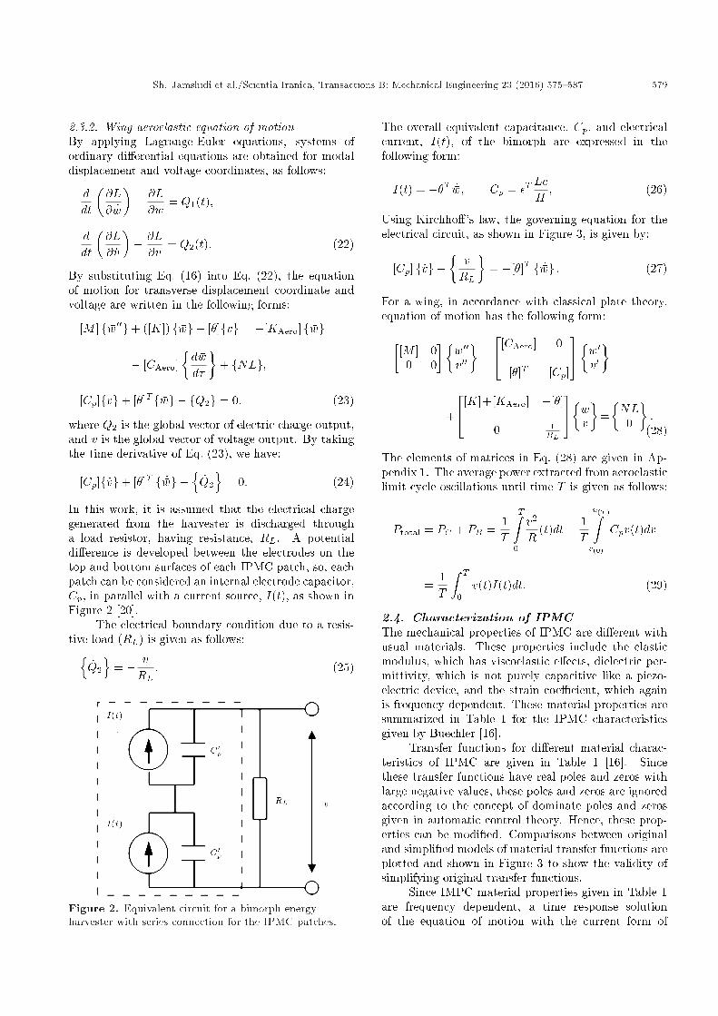
In this work, it is assumed that the electrical chargegenerated from the harvester is discharged througha load resistor, having resistance, RL. A potentialdi�erence is developed between the electrodes on thetop and bottom surfaces of each IPMC patch, so, eachpatch can be considered an internal electrode capacitor,Cp, in parallel with a current source, I(t), as shown inFigure 2 [20].
The electrical boundary condition due to a resis-tive load (RL) is given as follows:n
_Q2
o= � v
RL: (25)
Figure 2. Equivalent circuit for a bimorph energyharvester with series connection for the IPMC patches.
The overall equivalent capacitance, Cp, and electricalcurrent, I(t), of the bimorph are expressed in thefollowing form:
I(t) = ��T _�w; Cp = �TLcH; (26)
Using Kirchho�'s law, the governing equation for theelectrical circuit, as shown in Figure 3, is given by:
[Cp] f _vg+�vRL
�= �[�]T f _�wg : (27)
For a wing, in accordance with classical plate theory,equation of motion has the following form:�
[M ] 00 0
���w00v00�
+
24[CAero] 0
[�]T [Cp]
35� �w0v0�
+
24[K]+[KAero] �[�]
0 1RL
35� �wv
�=�NL0
�:
(28)
The elements of matrices in Eq. (28) are given in Ap-pendix 1. The average power extracted from aeroelasticlimit cycle oscillations until time T is given as follows:
Ptotal = PC + PR =1T
TZ0
v2
R(t)dt+
1T
v(T )Zv(0)
Cpv(t)dv
=1T
Z T
0v(t)I(t)dt: (29)
2.4. Characterization of IPMCThe mechanical properties of IPMC are di�erent withusual materials. These properties include the elasticmodulus, which has viscoelastic e�ects, dielectric per-mittivity, which is not purely capacitive like a piezo-electric device, and the strain coe�cient, which againis frequency dependent. These material properties aresummarized in Table 1 for the IPMC characteristicsgiven by Buechler [16].
Transfer functions for di�erent material charac-teristics of IPMC are given in Table 1 [16]. Sincethese transfer functions have real poles and zeros withlarge negative values, these poles and zeros are ignoredaccording to the concept of dominate poles and zerosgiven in automatic control theory. Hence, these prop-erties can be modi�ed. Comparisons between originaland simpli�ed models of material transfer functions areplotted and shown in Figure 3 to show the validity ofsimplifying original transfer functions.
Since IMPC material properties given in Table 1are frequency dependent, a time response solutionof the equation of motion with the current form of

580 Sh. Jamshidi et al./Scientia Iranica, Transactions B: Mechanical Engineering 23 (2016) 575{587
Figure 3. Material characterizations of selected IPMC (Buechler [16] vs. its simpli�ed model).
Table 1. Material properties of selected IPMC.
Buechler model [16] Simpli�ed models
d�mv
� �216� 10�6 s+15(s+0:6)(s+14)(s+11000) �7:3� 10�8 1
s+0:6
�� Fm
�950� 10�2 (s+18:96)(s+69:08)(s+84:48t)
(s+0:23)(s+18:83)(s+89:71)(s+10000) 4:5� 10�4 s+69:08s+0:23
Y (MPa) 150� �1 + 0:22 s2+12�106ss2+12�106s+1:44�1010
�50� �1 + 0:22 s
s+1:2�103
�equations of motion is not possible. Hence, it isnecessary to include frequency dependent propertiesdirectly in the equation of motion. For this purpose, at�rst, it is necessary to drive the equation of motion inthe frequency domain as follows. By taking the Laplacetransform of Eq. (28), we have:
([M ]s2 +[CAero]s+[K+KAero]) f �w(s)g � [�]fv(s)g= fNL(s)g;
s[�]T f �w(s)g+�Cps+
1RL
�fv(s)g = 0: (30)
As seen from Table 1, the transfer function for d, �,and Y have numerator and denominator polynomialsin terms of \s". The idea is to transfer Eq. (30) fromthe frequency domain to the time domain, using thefollowing equality:
snQ(s) =@nq(t)@tn
: (31)
By multiplying each equation of Eq. (30) in the com-mon denominator of all terms, and using the idea given
by Eq. (31), Eqs. (30) can be written as:
5Xn=0
c1nw
�@n �w@�n
��
2Xn=0
c1nv
�@nv@�n
�= [NL]d;
3Xn=0
c1nw
�@n �w@�n
�+
4Xn=0
c1nv
�@nv@�n
�= 0: (32)
2.5. Selection of the appropriate modefunctions
According to the Rayleigh-Ritz method, the modefunctions necessary to describe di�erent displacementsof the problem must satisfy the geometric boundaryconditions. Mode functions of a classical plate theorycan be obtained from its one dimensional equivalenttheory. Hence, for classical plate theory, transversemode functions of a beam, according to the Euler-Bernoulli beam, can be used. It is noted that theboundary conditions of the wing are considered to beclamped at one edge and free at three other edges.Hence, mode shapes of the cantilever and free-freebeams can be used for this purpose [21]. For the

Sh. Jamshidi et al./Scientia Iranica, Transactions B: Mechanical Engineering 23 (2016) 575{587 581
free free beam, two rigid modes are necessary to beconsidered.
Now, after presenting energy harvesting andaeroelastic equations, the results obtained from theseequations are given.
3. Result and discussion
In this study, the aeroelastic and energy harvestingcharacteristics of the rectangular wing model of a wingis considered. The plate is considered an aluminumalloy with an aspect ratio of AR = L=c = 1, streamwise length of c = 0:3 m, thickness of h = 0:001 m, andPoisson's ratio of � = 0:3. For transverse displacement,eight mode numbers are selected; four in streamwiseand two in span-wise directions. In the present study,IPMC patches with dimensions of 38 mm � 38 mm �0:3 mm are considered [16]. A Li+cation is themobile ion and EmI-Tf ionic liquid is the solvent.The electrode is created with RuO2 and Na�onTM.The outer electrode is gold leaf, which is hot pressedonto the sample. This method of manufacturing wasrecently developed by Akle, Bennett, and Leo, andit is shown that high strain air-stable actuators andsensors are produced [22]. The selected mechanicaland geometrical properties of the considered wing andIPMC models are listed in Table 2.
Typical dimensionless displacements and de ec-tions for the following results are plotted for point�x = 1 and �y = 1 of the wing.
3.1. Stability analysis and aeroelasticcharacteristics of wing without IPMCpatches
At �rst, the validity of the aeroelasticmodel is studied.To validate the presented equations for a rectangularcantilever wing, LCO amplitude is investigated for twoaspect ratios and the results are compared with thesolutions given by Weiliang and Dowell [23]. The re-sults presented in [20] are for a wing modeled accordingto classical plate theory and considering von-Karmanstrains. It should be mentioned that in Weiliang's
work, simulations are carried out for point �x = 0:75and �y = 1.
A stability analysis of the aeroelastic system isachieved through an eigenvalue analysis of the lin-earized system at various aerodynamic pressures. Forthis purpose, the nonlinear structural terms of Eq. (33)should be linearized at the corresponding equilibriumpoint. The equilibrium point of the aeroelastic equa-tions can be obtained by equating all time derivativesof the state variable to zero. Then, by determiningthe Jacobian of the nonlinear structural terms ateach equilibrium point, a linearized aeroelastic modelwill be obtained. These eigenvalues determine thestability of the system. When the real part of oneof the eigenvalues becomes positive, the entire systembecomes unstable. The dynamic pressure at whichpurely imaginary eigenvalues occur, and the system ison the verge of instability is considered critical dynamicor utter pressure and is indicated by �f .
At �rst, the eigenvalue analysis of the wing modelfor an aspect ratio of 1 is shown in Figure 4. In this�gure, the real part of the eigenvalues of the aeroelastic
Figure 4. Variation of real part of eignevalues vs.dynamic pressure for aeroelastic wing model with AR = 1.
Table 2. Mechanical and geometrical properties of IPMC layer and wing.
IPMC
Tensile static modulus, Y (MPa) 150 Length, Li (mm) 38
Density, �i (kg/m3) 2600 Width, Li (mm) 38
Poisson's ratio, �i 0.3 Thickness, H (mm) 0.3
Resistance load, RL 500
Wing
Tensile static modulus, Ep (GPa) 70 Length, L (mm) 300
Density, �p (kg/M3) 2700 Width, c (mm) 300
Poisson's ratio, �p 0.3 Thickness, hp (mm) 1

582 Sh. Jamshidi et al./Scientia Iranica, Transactions B: Mechanical Engineering 23 (2016) 575{587
Figure 5. Variation of imaginary part of eignevalues vs.its real part for aeroelastic wing model with AR = 1.
model vs. dynamic pressures is shown. The real partsof the eigenvalues show the stability of the linearizedmodel of the original nonlinear system. Up to adynamic pressure of 100, the system is stable, since alleignevalues have a negative real part. But, at �f = 100,the �rst intersection of the eigenvalues branches withthe dynamic pressures axis; the related real part is zeroand dominant eigenvalues are purely imaginary. Theaerodynamic pressure of �f = 100 shows the criticaldimensionless aerodynamic pressure of the wing modeland, after that, the system becomes unstable. Thecalculated critical dynamic pressures for varying aspectratios are shown in Figure 5. As seen from this �gure,there is complete agreement between these results withthose given by Weiliang and Dowell [23].
Comparisons of the Limit Cycle Oscillation(LCO) amplitudes for dynamic pressures greater thanthe critical dynamic pressure of a wing with AR = 1is shown in Figure 6. The obtained results are in goodconformity with results presented in [23].
To determine the number of required mode shapesfor expressing the transverse displacement of this aeroe-lastic model, the transverse limit cycle amplitudes ofthe wing, in terms of di�erent numbers of mode shape,are investigated. From this investigation, eight modes,four in chord-wise and two in span-wise directions, aresu�cient for the convergence of the solution.
3.2. The e�ect of IPMC patches on naturalfrequency and stability
In this section, the e�ect of attached IPMC patcheson the natural frequency and stability of a wing isconsidered. IPMC patches are attached on the wingin nine positions, according to Figure 7. It should benoted that each pair of IPMC patches are attached tothe wing in a bimorph con�guration.
Since the IPMC patches have mass and sti�ness,
Figure 6. Transverse limit cycle oscillation for twodi�erent aluminum wings at di�erent dynamic pressures.
Figure 7. Di�erent locations of embedded IPMCs on thewing.
which in uence the natural frequency of the wing,their e�ect on natural vibration characteristics are �rstconsidered and, then, their e�ects on the stabilitydomain and the utter margin. The natural frequencyof the wing for each pair of IPMC's, according toFigure 7, is shown in Table 3. In this table, thetype of natural frequency, in terms of bending andtorsion mode, is also stated. As can be seen, attachedIPMC change the natural frequency of the wing. Dueto the symmetry, this e�ect for P1, P2, and P3 isthe same as P7, P8 and P9, respectively. Onlyat three positions of P1, P4, and P7, are naturalfrequencies increased. Torsional frequencies at P2and P8 are more reduced than P5. The generalargument regarding the e�ect of IPMC patches on

Sh. Jamshidi et al./Scientia Iranica, Transactions B: Mechanical Engineering 23 (2016) 575{587 583
Table 3. Dimensionless natural frequencies for wing with AR = 1 for di�erent locations of IPMC patches.
IPMC location ! Originalwing
P1 P2 P3 P4 P5 P6 P7 P8 P9Natural frequency #
!1 3.5036 3.5041 3.4993 3.4517 3.5042 3.4988 3.4509 3.5041 3.4993 3.4517
!2 8.5560 8.5574 8.5112 8.3357 8.5561 8.5553 8.5492 8.5574 8.5112 8.3357
!3 21.5070 21.5082 21.2285 21.4298 21.5076 21.3917 21.1995 21.5082 21.2285 21.4298
!4 27.6255 27.6257 27.5553 26.8078 27.6255 27.4475 27.4387 27.6257 27.5553 26.8078
!5 31.6597 31.6583 31.1485 31.1094 31.6598 31.6430 31.6236 31.6583 31.1485 31.1094
natural frequency characteristics is as follows. At theroots of the wing, i.e. at its clamping point, since theamount of strain is high and its displacement is small,the amount of change in the sti�ness of the wing ishigh, and the change in the mass of the wing is lowerthan at other positions. Hence, for these locations,natural frequencies will be increased. At the tip ofthe wing, the displacement is high, but its strain issmall due to the free edge boundary conditions. Hence,the equivalent mass of the wing will be increased,with respect to sti�ness. Accordingly, the naturalfrequency will be reduced. With this given description,location 4 has higher equivalent sti�ness and lowerequivalent mass, with respect to other locations ofIPMC.
In Figure 8, critical dynamic pressures of thewing, with AR = 1, and IPMC locations accordingto Figure 7, are presented. It can be seen that forposition 3 of IPMC, the utter margin is increased,which is embedded in the upper corner of the leadingedge. Embedding IPMC near to the root of the wing(cantilever edge) has little e�ect on the critical dynamicpressure. IPMC at position 9 has a minimum uttermargin, where IPMC is embedded at the upper cornerof the wing. Whenever IPMC's position is closer to
Figure 8. Critical dynamic pressures for wing withAR = 1 and embedded IPMC at di�erent locations.
the upper corner (�x = 1, �y = 1), the utter margin isfurther reduced.
The obtained results for critical dynamic pres-sures are not in conformity with the results obtainedfrom natural frequency examination. This di�erenceis due to the role of the aerodynamics force and themass and sti�ness e�ects of IPMCs. According toEqs. (19) and (23), the aerodynamics force inducessti�ness and damping forces. These characteristics aredependent on the dynamic pressures. Hence, the aeroe-lastic characteristics of the wing will vary at di�erentpressures. Dominate eigenvalues of linearized aeroelas-tic equations versus dynamic pressures are shown inFigure 9. From Figure 10, it is clear that the dominateeigenvalues of the wing at various dynamic pressuresare di�erent from the original wing, i.e. at dynamicpressures of zero. In this �gure, the lowest frequency isfor the �rst bending mode, whose frequency is nearlyconstant with the dynamic pressure. The second modeis the torsion mode, whose frequency is continuouslyreduced with dynamic pressure. The same conditionsare presented for two other dominate modes. Theseresults con�rm the in uence of aerodynamics force onthe natural frequencies of the aeroelastic system.
Figure 9. Comparison between utter margin to IPMClocations of 3 and 9, for wing with AR = 1.

584 Sh. Jamshidi et al./Scientia Iranica, Transactions B: Mechanical Engineering 23 (2016) 575{587
Figure 10. LCO of wings with and without energy harvesting at � = 55, and IPMC at location of P1.
As seen in a close-up view of Figure 10, theeigenvalues of the wing with IPMC at position 3 aregreater than at position 9. Accordingly, the critical dy-namic pressure will be greater, which veri�es the resultshown in Figure 8. The utter type for this aeroelasticmodel is of a bending-torsion type. In this type of utter, with increasing dynamic pressure, two di�erentmodes of the wing, i.e. bending and torsion modes,approach each other. When the distance betweenthese two modes becomes su�ciently small, utteroccurs due to the beating or resonance phenomenon. Iftwo branches of frequencies reach each other at lowerdynamic pressure, utter occurs sooner, and if theyreach each other at greater dynamic pressures, utteroccurs later. As seen from Figure 9, for cases 9 and 3,these two branches reach sooner and later than othercases, respectively. Hence, the results given in Figure 8can be justi�ed.
Now, the e�ects of energy harvesting on criticaldynamic pressure are considered. For this purpose,the real and imaginary parts of the eigenvalues of thelinearized aeroelastic model with energy harvesting areshown in Figures 11 and 12, and the obtained resultsare compared with the case without the harvester.IPMC at location P1 is considered. As seen from this�gure, energy harvesting does not change the uttermargin. This means that the stability of the aeroelasticmodel with and without energy harvesting is nearlythe same. The role of energy harvesting will be betterstudied by investigating the limit cycle oscillation of awing.
Imaginary versus real parts of the eigenvaluesof linearized aeroelastic equations, with and withoutenergy harvesting, for a wing with AR = 1 and IPMCat position 1, are shown in Figure 12. As seen from this�gure, eigenvalues for these two cases are completelythe same, and this implies that the damping andfrequency of the system for these two cases are not
Figure 11. Real part eigenvalues vs. dynamic pressureswith and without energy harvesting.
in uenced by harvesting the energy. Accordingly, the utter margin of the aeroelastic system in these twocases is the same.
3.3. Investigating the e�ect of energyharvesting on limit cycle oscillations
In this section, the e�ect of IPMC patches on thenonlinear behavior of the considered wing model isinvestigated. Two cases of without and with energyharvesting are studied. For the �rst case, the e�ect ofstructural characteristics of IPMC on nonlinear aeroe-lastic characteristics, such as Limit Cycle Oscillation(LCO) amplitude, will be studied, and, in the secondcase, the amount of decrease in LCO amplitude will beconsidered.

Sh. Jamshidi et al./Scientia Iranica, Transactions B: Mechanical Engineering 23 (2016) 575{587 585
Figure 12. Imaginary vs. real part of eigenvalues oflinearized aeroelastic equations with and without energyharvesting for wing with AR = 1 and IPMC at position 1.
Dimensionless transverse displacement and limitcycle oscillations, with and without energy harvesting,for a wing with AR = 1 and IPMC location of 1 at� = 55 are shown in Figure 10. As seen from this�gure, the e�ect of energy harvesting on reducing theamplitude of the limit cycle oscillation is considerable,although its e�ect on utter margin is not.
3.4. Investigation of the e�ect of position ofIPMC on Limit Cycle Oscillations (LCO)
Transverse displacements of wing for di�erent positionsof IPMC at three dimensionless aerodynamics pres-sures are shown in Figure 13. As seen from this �gure,
when energy is harvested from the system, oscillationsof the wing are around a non-zero equilibrium point. Inother words, the wing has a static de ection. Also, asseen from this �gure, the amount of reduction in LCOamplitude, due to energy harvesting through IPMCpatches, is considerable, especially at higher dynamicspressures.
Now, there is an important question. Whileenergy harvesting does not have a considerable e�ect onthe utter boundary, how is this amplitude reduction inlimit cycle oscillation justi�ed? Figures 10 and 13 showthat when energy is extracted from wing oscillations,a static de ection is produced. Considering thatthe IPMC has a high level of strain, the resultingstatic de ection can be considerable. Static de ectionresults in nonlinear sti�ness terms that have an odddegree (third for single mode, and higher for multiplemode), and produces sti�ness hardening. As a result,the sti�ness of the entire system increases and theamplitude of oscillations is reduced.
3.5. Investigation of the e�ect of IPMCpatch's position on the harvested power
The amount of power produced by IPMC patches forthe wing with AR = 1 is shown in Figures 14. Meanoutput power is calculated as P (T ) = 1
T
R T0 v(t)I(t)dt.
As seen from Figure 14, for this dynamic pressure, themaximum harvested power is about 0.17 mW at � =55, which is related to the IPMC at position 4.
Figure 13. LCO of wing with energy harvesting for all locations of IPMC at � = 40, 45, 55.

586 Sh. Jamshidi et al./Scientia Iranica, Transactions B: Mechanical Engineering 23 (2016) 575{587
Figure 14. Power produced from LCO for nine locations of IPMC at � = 40, 45, 50.
4. Conclusion
In this work, energy harvesting from an aeroelastic sys-tem by ionic polymer metal composites in supersonic ow is studied. The aerodynamic pressure is evaluatedbased on the quasi-steady �rst-order piston theory.Characteristics of the IPMC depend on frequency.They typically cannot be modeled in the time domain.Hence, by proposing a new idea, electromechanicalequations are transferred into the time domain. Thee�ects of the mass and sti�ness of the polymer em-bedded on the wing were also studied. WheneverIPMC is embedded closer to the cantilever edge ofthe wing, the power delivered to the electric circuitbecomes greater. At higher dynamic pressure, theharvested power increases. Energy harvesting does notchange the utter margin. When energy is harvested,the wing has a static de ection. Considering thatthe IPMC has a high level of strain, the resultingstatic de ection can be considerable. Nonlinear hard-ening sti�ness is resulted from this static de ection.Accordingly, the total sti�ness of the entire systemwill be increased and the amplitude of oscillationswill be reduced. This is the reason for the highamount of reduction in the amplitude of limit cycleoscillations.
References
1. Bar-Cohen, Y., Electroactive Polymer (EAP) Actu-ators as Arti�cial Muscles Reality, Potential, andChallenges, SPIE Press, Bellingham, WA (2001).
2. Leo, D.J. \Active materials and smart structures - I",Course Notes, Virginia Tech course ME 5984 (2003).
3. Sodano, H., Inman, D.J. and Park, G. \A review ofpower harvesting from vibration using piezoelectricmaterials", The Shock and Vibration Digest, 36, pp.197-205 (2004).
4. Eichorn C., Goldschmidtboeing, F. and Woias, P. \Afrequency tunable piezoelectric energy converter basedon a cantilever beam", In Proceedings of Power MEMS2008 Micro EMS2008, pp. 309-312 (2008).
5. St Clair, D., Bibo, A., Sennakesavababu, V.R., Daqaq,M.F. and Li, G. \A scalable concept for microp-ower generation using ow-induced self-excited oscil-lations", Applied Physics Letters, 96, pp. 144103-1-144103-3 (2010).
6. Bernitsas, M., Raghavan, K., Ben-Simon, Y. and Gar-cia, E. \VIVACE (Vortex Induced Vibration AquaticClean Energy): a new concept in generation of cleanand renewable energy from uid ow", Journal ofO�shore Mechanics and Arctic Engineering, 130, pp.041101-1-041101-15 (2008).

Sh. Jamshidi et al./Scientia Iranica, Transactions B: Mechanical Engineering 23 (2016) 575{587 587
7. Akaydin, H.D., Elvin, N. and Andreopoulos, Y. \Wakeof a cylinder: paradigm for energy harvesting withpiezoelectric materials", Experimental Fluids, 49, pp.291-304 (2009).
8. Erturk, A., Vieira, W.G.R., DeMarqui, C. and Inman,D.J. \On the energy harvesting potential of piezo-aeroelastic systems", Applied Physics Letters, 96, pp.184103-1-184103-3 (2010).
9. De Marqui, C., Erturk, A. and Inman, D.J. \Piezo-aeroelastic modeling and analysis a generator wingwith continuous and segmented electrodes", Journalof Intelligent Material Systems and Structures, 21, pp.983-993 (2010).
10. Taylor, G.W., Burns, J.R., Kamann, S.M., Power,W.B. and Welsh, T.R. \The energy harvesting Eel: asmall subsurface ocean/river power generator", IEEEJournal of Oceanic Engineering, 26, pp. 539-547(2001).
11. Dunnmon, J.A., Stanton, S.C., Mann, B.P. and Dow-ell, E.H. \Power extraction from aeroelastic limitcycle oscillations", Journal of Fluids and Structures,27(8), pp. 1182-1198 (Nov. 2011) ISSN 0889-9746,http://dx.doi.org/10.1016/j.j uidstructs.2011.02.003.
12. Dowell, E.H., Edwards, J. and Strganac, T.W. \Non-linear aeroelasticity", J. Aircraft, 40(5), pp. 857-874(2003).
13. Dowell, E.H., Aeroelasticity of Wings and Shells, No-ordho� International Publishing Company, Liyden, pp.1-9, 19-26 (1975).
14. Hall, K.C. \Eigenanalysis of unsteady ows aboutairfoils, cascades, and wings", AIAA J., 32(12), pp.2426-2432 (1994).
15. Reddy, J.N., Mechanics of Laminated CompositeWings and Shells: Theory and Analysis, Second Ed.,CRC Press, Boca Raton (2003).
16. Bucchler, M.A. \Variational modeling of ionicpolymer-based structures", MS Thesis, Virginia Poly-technic Institute and State University (2005).
17. Samuel, C. \Stanton, nonlinear electroelastic dynami-cal systems for inertial power generation", PhD Thesis,Department of Mechanical Engineering and MaterialsScience, Duke University (2011).
18. Xue, D.Y. \Finite element frequency domain solutionof nonlinear panel utter with temperature e�ects andfatigue life analysis", PhD Dissertation, EngineeringMechanics, Old Dominion University, Norfolk, VA(1991).
19. Vedeneev, V.V. \Panel utter at low supersonicspeeds", J. Fluid Structure, 29, pp. 79-96Y (2012).
20. Weiliang, Y.E. and Dowell, E.H. \Limit cycle oscilla-tion of a uttering cantilever plate", AIAA Journal,29(11), pp. 1929-1936 (1991).
21. Preumont, A., Dynamics of Electromechanical andPiezoelectric Systems, Springer, Brussels (2006).
22. Rao, S.S., Vibration of Continuous Systems, Wiley,New Jersey (2007).
23. Akle, B.J., Bennett, M.D. and Leo, D.J. \High-strain ionomeric-ionic liquid composites via electrodetailoring", Proceedings of IMECE, No. 61246 (2004).
Biographies
Shahab Jamshidi received BS and MS degrees inEngineering Mechanics, in 2011 and 2013, respec-tively, from Babol University of Technology, Iran.His research interests include mechanical nonlinearvibrations and dynamics, smart structures, energyharvesting, aeroelasticity, and liquid sloshing ynamics.
Morteza Dardel received a PhD degree from Amirk-abir University, Iran, in Solid Mechanics, in 2009,and is currently Assistant Professor in the Facultyof Mechanical Engineering at Babol Noushirvani Uni-versity of Technology, Iran. His research interestsare aeroelasticity, nonlinear dynamics, vibration, andcontrol of continuous systems and smart structures.
Mohammad Hadi Pashaei received a PhD degree inSpace Structures from the University of Surrey, UK, in2004, and is currently Assistant Professor in the Fac-ulty of Mechanical Engineering at Babol NoushirvaniUniversity of Technology, Iran.. His research interestsinclude structural dynamics, damping in structures,and vibrational systems analysis.